Article

Collaborative Storage and Resolution Method between Layers in Hierarchical ICN Name Resolution Systems

1
National Network New Media Engineering Research Center, Institute of Acoustics, Chinese Academy of Sciences, No. 21, North Fourth Ring Road, Haidian District, Beijing 100190, China
2
School of Electronic, Electrical and Communication Engineering, University of Chinese Academy of Sciences, No. 19(A), Yuquan Road, Shijingshan District, Beijing 100049, China
*
Author to whom correspondence should be addressed.
Future Internet 2023, 15(2), 74; https://doi.org/10.3390/fi15020074
Submission received: 29 November 2022 / Revised: 9 February 2023 / Accepted: 10 February 2023 / Published: 13 February 2023

Abstract

:
Name resolution system is an important infrastructure in Information Centric Networking (ICN) network architecture of identifier–locator separation mode. In the Local Name Resolution System (LNMRS), a hierarchical name resolution system for latency-sensitive scenarios; higher-level resolution nodes serve more users and suffer more storage pressure, which causes the problem of unbalanced storage load between layers, and requires inter-layer collaborative storage under the constraint of deterministic service latency characteristics. In this paper, we use the constraints required for inter-layer collaborative resolution to construct an index neighbor structure and perform collaborative storage based on this structure. This method relieves storage pressure on high-level resolution nodes. Experimental results show that the increase of total storage load brought by the proposed method is 57.1% of that by MGreedy algorithm, 8.1% of that by Greedy algorithm, and 0.8% of that by the K-Mediod algorithm when relieving the same storage load for high-level resolution nodes. Meanwhile, deterministic service latency feature is still sustained when our proposed method is used for collaborative resolution.

1. Introduction

ICN is an emerging future network architecture proposed in recent years [1,2,3,4,5]. ICN takes information as the center of the network, which adopts the paradigm of separation of the identifier and locator, and shifts the communication model from host-centric to information-centric. In-network caching, mobility, security, and other features are easily supported in ICN, which is compatible with the requirements of emerging applications such as IoT, big data, and cloud computing [6,7,8,9,10]. According to the mode of routing and forwarding, ICN architectures can be classified into two categories [11,12,13]: identifier-based routing mode and identifier–locator separation mode. In the ICN architecture of identifier-based routing mode, routing and forwarding are coupled, which cannot realize smooth transition with IP networks and is difficult to solve the problem of routing scalability. In the ICN architecture of identifier–locator separation mode, an independent name resolution system is responsible for the identifier to locator mapping, and content delivery cannot be achieved unless the name resolution process is completed. Here, the routing and forwarding process are decoupled, and could evolve separately. In the scenario of IP and ICN hybrid networking, the identifier–locator separation mode is mostly adopted, in which the name resolution system is an important infrastructure.

1.1. Name Resolution Systems in ICN

ICN name resolution system structure is classified into single-layer structure and hierarchical structure, and the hierarchical structure is further classified into tree-based hierarchical structure and DHT-based hierarchical structure [14,15,16,17]. In the name resolution system with single-layer structure, the DHT algorithm is performed for structure maintenance, storage, and resolution of mapping records among resolution nodes. A resolution system with single-layer structure can achieve good storage load balancing among resolution nodes, but a resolution request may be redirected several times before it is responded to, which leads to high resolution latency. In a hierarchical name resolution system, resolution nodes in the same network region form a local structure, and one of them is considered a super node of this local structure and participates in the construction of structure among resolution nodes in the larger network region (the upper layer). Here, resolution of a mapping record is firstly performed in the local structure; if it fails, it is performed in the upper layer, until the resolution process reaches the top layer. Hierarchical name resolution systems take storage localization as a character, which also brings a kind of load balancing. In a tree-based hierarchical name resolution system, resolution nodes in the same region form a tree structure, in a DHT-based hierarchical name resolution system; resolution nodes in the same region form DHT structure.
LNMRS is a tree-based hierarchical name resolution system [18,19,20,21,22,23], which is designed mainly for latency-sensitive application scenarios. In LNMRS, users of each name resolution node form the service area of that node, and a resolution node provides name resolution service with deterministic service latency only to users in its service area. The deterministic service latency value of name resolution nodes in the same level is the same, and the deterministic service latency value of high-level name resolution nodes is larger than that of low-level name resolution nodes. At the same time, service area of a low-level name resolution node is completely included by the service area of its parent node. High-level name resolution nodes cover more users and suffer larger storage pressure, while low-level name resolution nodes suffer smaller storage pressure, which causes the problem of unbalanced storage load between layers in LNMRS. It is worth studying inter-layer collaborative storage and resolution under the constraint of a deterministic service latency feature to achieve better storage load balancing in LNMRS.

1.2. Collaborative Storage and Resolution Methods

Name resolution systems with different structures use different collaborative storage and resolution methods. In name resolution systems based on single-layer structure (e.g., NetInf [24], DHT-NRS [25], etc.), when resolution requests cannot be fulfilled locally, the resolution request is routed to the next resolution node according to different DHT implementations. In tree-based hierarchical name resolution systems (e.g., DONA [26], Ftree [27], etc.), resolution requests are forwarded up along the tree structure until the request is fulfiled by a resolution node or the request reaches the root of the tree structure. In DHT-based hierarchical name resolution systems (e.g., MDHT [28], HSkip [29], etc.), if a resolution request is not fulfilled locally, it is firstly redirected in the local DHT structure; if it is still not fulfilled, it will be redirected by the super node in the local structure to nodes in the DHT structure of the higher level, until it reaches the highest level. In LNMRS, a user can only resolve mapping records from the resolution node in whose service area it resides, and it is because of this special service pattern that resolution service latency is guaranteed to be smaller than a deterministic latency value. If a user sends a resolution request to a resolution node outside of the service area it resides in, as in the commonly used collaborative resolution methods mentioned above, the special service pattern is violated, and the resolution service latency cannot be guaranteed.
In this paper, we propose a collaborative storage and resolution method between layers under the constraint of deterministic service latency feature in LNMRS, by which resolution nodes with excessive storage load could store part of the mapping records to the child nodes with a lighter storage load, which relieves storage pressure on higher-level resolution nodes and improves the overall storage resource utilization of the system. The main contributions of this paper are as follows:
  • We analyze latency constraints required for inter-layer collaborative storage and resolution under the constraint of a deterministic service latency feature, and define the nodes that satisfy the above constraints as index neighbors. Then we propose an index neighbor construction method based on the MK-Mediod algorithm.
  • We propose the collaborative storage and resolution method based on index neighbor structure, and conduct experiments to compare the latency measurement cost and computation cost of our index neighbor construction algorithm against several other approaches. Meanwhile, experiments are also conducted to compare the increase of total storage load and service latency when the constructed index neighbor structure is used to implement collaborative storage and resolution.
The rest of this paper is organized as follows: in Section 2, we analyze latency constraints that need to be satisfied by the resolution nodes used for inter-layer collaborative storage in LNMRS, construct index neighbor structure based on the proposed MK-Mediod algorithm, and use this structure to implement inter-layer collaborative storage and resolution. In Section 3, we evaluate and discuss the performance of the proposed method through comparative experiments with several neighbor construction algorithms, and Section 4 concludes our work.

2. Materials and Methods

In LNMRS, resolution nodes at each level form a tree management structure according to service area inclusion relationship. The structure is defined and described in patent [30] and standards [20,21]. Paper [19] clarifies the mathematical principles of this structure and proposes algorithms for the construction of this structure, and paper [31] deals with the server placement problem in this system.
Figure 1 shows the service area inclusive relationship of resolution nodes in two levels, as well as the relationship with users in the physical network. The underlying network represents the physical network, the gray solid dots represent users, the two upper layers represents the distribution of resolution nodes at level i + 1 and level i, black solid dots represent resolution nodes, dashed circles represent the service areas of the resolution nodes. Dash circles in the physical network correspond to service areas in the two upper layers. The service area inclusive relationship between nodes in neighbor levels reflects the parent–child relationship of these nodes in the tree structure.
The following features of the LNMRS Structure will be used afterwards.
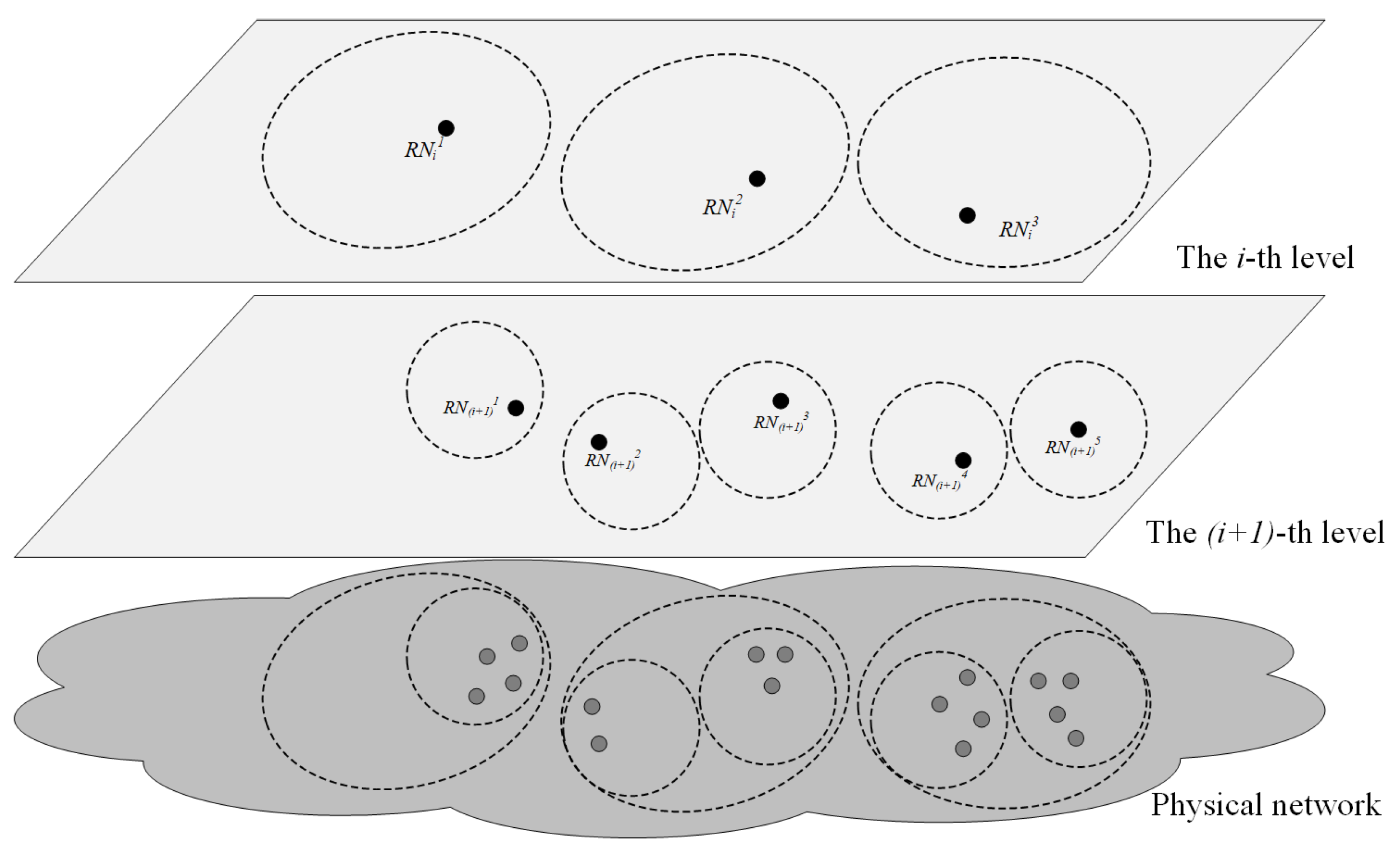
  • A resolution node provides a name resolution service with deterministic service latency only to users in its service area.
  • A user in the service area of a child node must also be in the service area of its parent node, a user in the service area of the parent node must also be in the service area of a particular child node of this parent node.
  • Deterministic service latency value of name resolution nodes in the same level is the same, while the deterministic service latency value of high-level name resolution nodes is larger than that of low-level name resolution nodes.

2.1. System Model

In LNMRS, if there is a resolution node R N i + 1 k , and its corresponding parent node is R N i , then for any user u i + 1 of R N i + 1 k , its corresponding resolution node in level i must be R N i . If some mapping records of R N i are stored on R N i + 1 k , the resolution service latency may still be guaranteed if a resolution request of u i + 1 is responded to by R N i + 1 k . Based on the above idea, in order to alleviate excessive storage pressure on high-level resolution nodes in LNMRS by collaboratively stored mapping records to low-level resolution nodes, we propose a collaborative storage and resolution method based on index neighbor structure. In this method, the higher-level resolution node stores some mapping records with compressed data structures such as BloomFilter, and these mapping records are stored actually in the index neighbor of this higher-level resolution node, and resolution requests related to these mapping records are finally responded to by the index neighbor. Here, the index neighbor must satisfy some certain latency constraints.
Considering that record mapping table lookup and index table lookup in memory are based on hash algorithm in microsecond order, and the resolution service latency is in millisecond order, processing latency on the resolution node is ignored when considering the resolution service latency.
Definition 1.
Index neighbor.
Index neighbor is a structural relationship among name resolution nodes. An index neighbor is dedicated for collaboratively storing and resolving mapping records for high-level resolution nodes, an example index neighbor structure of the name resolution node R N i is shown in Figure 2, and the latency constraint that the index neighbor should meet is in Equation (1).
i n d e x N e i k = { R N i + 1 k | l a t e n c y ( u i , R N i ) + l a t e n c y ( R N i , R N i + 1 k ) + l a t e n c y ( R N i + 1 k , u i ) < = 2 * T i , u i U ( R N i ) }
In the above equation, R N i denotes any resolution node in level i, which is called the master node in index neighbor context, u i denotes any user in U ( R N i ), T i is the deterministic latency value corresponding to level L i , R N i + 1 k denotes an index neighbor of the master node, and l a t e n c y ( u i , R N i ) + l a t e n c y ( R N i , R N i + 1 k ) + l a t e n c y ( R N i + 1 k , u i ) is the round-trip latency of the resolution service procedure, where the request is sent to R N i from u i , and then redirected to R N i + 1 k and is responsed by R N i + 1 k . From the formula we can see that if the latency between R N i and R N i + 1 k , and the latency between R N i + 1 k and u i , is delicately constrained, the whole service latency might be smaller than the pre-defined upper bound.
Definition 2.
Index neighbor group.
The definition of the index neighbor is closely related to users of the master node. To construct an index neighbor structure, the most ideal situation is that the index neighbor resolution node could provide resolution service for all users of the master node within a deterministic latency upper bound. However, this constraint is too strict, and it may be possible that none of the lower-level resolution nodes satisfy the latency constraint of Equation (1) for all users of the master node. Alternatively, we divide the lower-level resolution nodes into groups, and as long as an index neighbor can be found in each group to satisfy Equation (1) for all users within that group, then Equation (1) can be satisfied for all users of the master node as well, as shown in Figure 3. In this situation, mapping records that need to be collaboratively stored for the master node will be assigned one copy to each index neighbor group for the purpose that these mapping records could be resolved by any user in different groups. Based on the above idea, the concept of index neighbor group is proposed as follows.
i n d e x N G k ( R N i ) = { i n d e x N e i k , [ R N i + 1 1 , , R N i + 1 n ] | l a t e n c y ( u i , R N i ) + l a t e n c y ( R N i , i n d e x N e i k ) + l a t e n c y ( i n d e x N e i k , u i ) < = 2 T i , u i { U ( R N i + 1 1 ) U ( R N i + 1 n ) } a n d u i U i }
In the above equation, an index neighbor group involves a master node, an index neighbor node, and a set of index neighbor group sub-nodes, where R N i denotes the master node in level i, i n d e x N G k ( R N i ) denotes the k-th index neighbor group of R N i , i n d e x N e i k denotes the index neighbor node in i n d e x N G k ( R N i ) , and [ R N i + 1 1 ,…, R N i + 1 n ] denotes the index neighbor group sub-nodes. The above inequality indicates that for any user of the sub-nodes, the corresponding index neighbor node in this group can provide a resolution service with deterministic service latency with the upper bound of T i , in the situation that this user sends a resolution request to the master node, and the request is then redirected to the index neighbor i n d e x N e i k , and the response is returned by the index neighbor finally.
In Equation (2), l a t e n c y ( u i , R N i ) denotes the latency from the user to the master node, which has an upper bound of T i according to the hierarchical structure of LNMRS. L a t e n c y ( R N i + 1 k , u i ) denotes the latency from the index neighbor to the user, assuming that the user’s corresponding resolution node in level i + 1 is R N i + 1 t , the latency from R N i + 1 t to this user has an upper bound T i + 1 . The latency from R N i + 1 k to R N i + 1 t is measurable. It can be inferred that the upper bound of l a t e n c y ( R N i + 1 k , u i ) is l a t e n c y ( R N i + 1 k , R N i + 1 t ) + T i + 1 . Since it is unpredictable which resolution node in level i + 1 u i corresponds to, the upper bound of l a t e n c y ( R N i + 1 k , u i ) is m a x ( l a t e n c y ( R N i + 1 k , R N i + 1 t ) ) + T i + 1 , where R N i + 1 t is any node in { R N i + 1 }. Therefore, the latency constraint in Equation (2) becomes
l a t e n c y ( R N i , R N i + 1 k ) + m a x ( l a t e n c y ( R N i + 1 k , R N i + 1 t ) ) < = T i T i + 1 , R N i + 1 t { R N i + 1 } .

2.2. Problem Statement

Constructing index neighbor structure is a problem that clusters the child nodes in different groups, where the groups must meet some latency constraint mentioned above; this is a typical combinatorial optimization problem. In a collaborative storage scenario, each group will be assigned one copy of the mapping records to be co-stored for the purpose that these mapping records could be resolved by all users of the master node, which will obviously bring much storage load to lower-level resolution nodes. Thus, we model the index neighbor construction problem as a combinatorial optimization problem with the objective of the minimum of the number of index neighbor groups, which means a minimum overall storage load of the system.
Minimize:
n u m b e r o f ( { i n d e x N G ( R N i ) } )
Subject to
R N i + 1 t i n d e x N G k ( R N i ) , R N i + 1 t { R N i + 1 } , i n d e x N G k ( R N i ) { i n d e x N G ( R N i ) }
l a t e n c y ( i n d e x N e i k , R N i + 1 t ) + l a t e n c y ( i n d e x N e i k , R N i ) < = T i T i + 1 , R N i + 1 t [ R N i + 1 1 , , R N i + 1 n ] o f i n d e x N G k ( R N i )

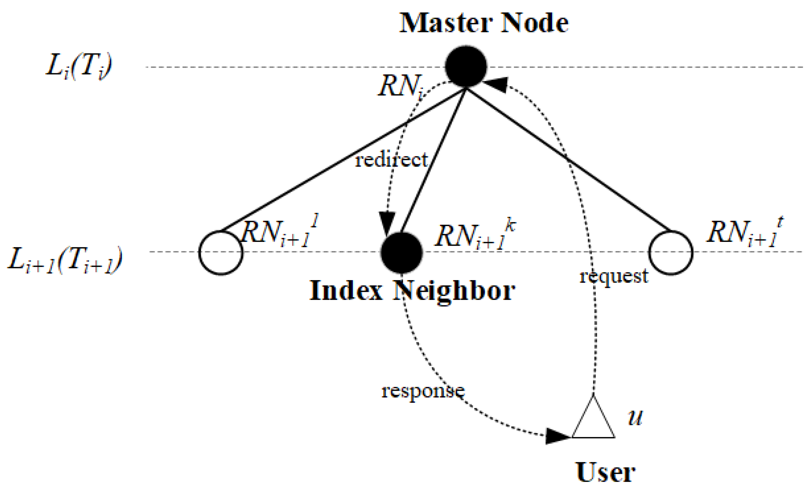
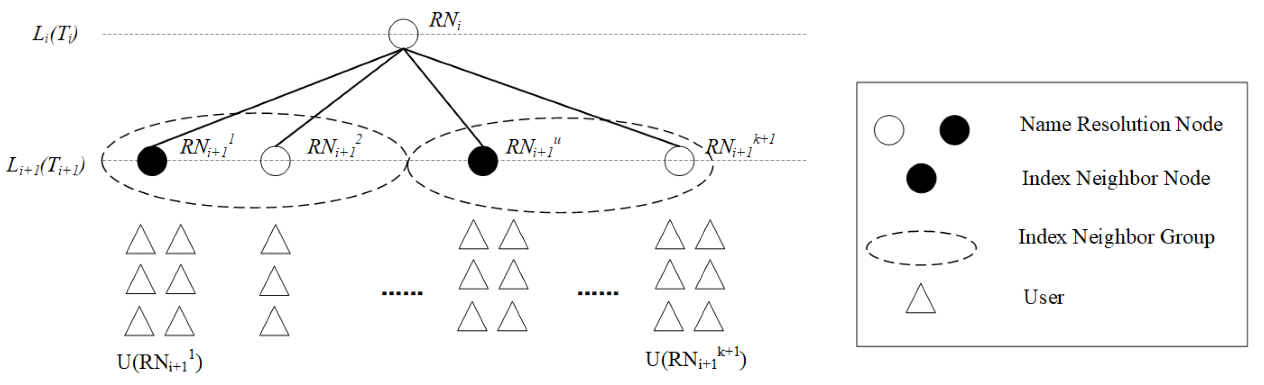
2.3. Collaborative Storage and Resolution Method with Index Neighbor Structure

2.3.1. Existence of Index Neighbor

Latency between users and resolution nodes in different levels is the only constraint in the LNMRS structure, it is not inevitable that there is one resolution node in the lower level that satisfies Equition (6) with this loose constraint. Therefore, the existence of index neighbors needs to be validated before the index neighbor structure is constructed. The purpose of the validation process is to find a feasible construction of index neighbors for the master node. In this paper we utilize a greedy method to seek a feasible construction: check whether each child of the master node can find its own corresponding index neighbor node in turn. If all child nodes could find their index neighbor nodes, it means that there is at least one feasible solution for the index neighbor construction algorithm. In detail, we first check whether a child node could serve as an index neighbor for itself, and if not, we try to check other sibling nodes if they could serve as an index neighbor and include this child node as a sub-node in its index neighbor group. The pseudo code of the validation process is shown in Algorithm 1.
Algorithm 1: Index Neighbor Existence Validation
      Input: master node R N i , child nodes { R N i + 1 } , T i , T i + 1
      Output: validation result
Futureinternet 15 00074 i001
The validation algorithm may make every child node an index neighbor in the extreme case, and the mapping records to be co-stored by the master node need to be placed in each child node with a copy, which will inevitably cause a large amount of redundancy in the system storage. The MK-Mediod algorithm proposed in this paper firstly clusters the child nodes, and then constructs index neighbor structure with the clustered results. This algorithm might construct less index neighbor groups, which in turn reduces storage costs of the whole system.

2.3.2. Index Neighbor Construction with MK-Mediod

How to combine child nodes of the master node as index neighbor groups so that at least one node in each group can be selected to meet the latency constraint mentioned above, and simultaneously, make the number of index neighbor groups as small as possible, is a typical combinatorial optimization problem, and is NP-hard. In this paper, we use a greedy algorithm to solve the problem, firstly we select a small number, cluster the child nodes according to the selected number, and then validate if each group could meet the requirements of the index neighbor group, that is to say, whether there is a node in this group meeting the above defined index neighbor latency constraint. If the validation is successful, the final result is found; otherwise, we increase the selected number and perform clustering and validation again, until the final result is obtained. The index neighbor construction process includes two parts, one is the clustering procedure, the other is the index neighbor structure validation procedure based on the clustering result.

MK-Mediod Algorithm

K-Means algorithm is the most classical division-based clustering method. The basic idea of K-Means algorithm is to cluster k points in the space as the center of mass and group the objects closest to them. By an iterative method, the value of each cluster center of mass is updated round by round until the best clustering result is obtained. However, the clustering result of the K-Means algorithm is easily affected by noise and isolated points. K-Mediod and K-Means algorithm are similar in basic idea, the biggest difference is that when updating the clustering center, K-Mediod calculates the minimum value of the distance from each point to all other points in the cluster except for the cluster center to optimize the new cluster center. It is this difference that makes up for the shortcomings of the K-Means algorithm.
For clustering child nodes, the original K-Mediod algorithm does not suit well in the following aspects: (i) the initial cluster center selection in the K-Mediod algorithm is random, thus it is easy to fall into a local optimum; (ii) the criterion of the cluster center selection in the K-Mediod algorithm is the minimum distance to all other points, but index neighbors should obey constraints in Equation (6), involving not only the distance from the cluster center to other nodes in the cluster, but also the distance from the cluster center to the master node.
Based on the two points above, this paper makes the following improvements to the K-Mediod algorithm: (i) firstly, the child nodes are sorted according to their latency to the master node, and child nodes that are closest to the master node are selected as the initial cluster centers; (ii) during the cluster centers updating procedure, the sum of minimum latency from the center to other nodes and latency from the center to master node is used as the selection criteria.

Index Neighbor Structure Construction Based on MK-Mediod Algorithm

The above MK-Mediod algorithm can cluster the child nodes into a given number of groups, and the clustering results can be validated as candidate index neighbor groups. The validation depends on whether the cluster center meets latency constraints in Equation (6). That is, the sum of the maximum latency from the cluster center to other nodes in the group and latency from the cluster center to the master node is within a certain latency constraint.
The main idea of our index neighbor construction algorithm proposed in this paper is to validate candidate groups in a greedy manner: firstly, we set group number to 1, cluster the child nodes into 1 cluster, and validate whether a node can be found in this group as an index neighbor node of the master node, which satisfies the latency constraint in Equation (6); if the validation is successful, then the construction procedure is over, and the index neighbor and corresponding index neighbor group are found. If it fails, then the group number is increased to 2, the child nodes are clustered into 2 clusters, and whether there could be an index neighbor node in each group is validated. If the validation succeeds, then the construction procedure is over, and the index neighbors and corresponding index neighbor groups are found. If it fails, then we increase the group number to 3, and repeat the same procedure until a final result is found. The algorithm pseudo code is shown in Algorithm 2.

2.3.3. Collaborative Storage and Resolution based on Index Neighbor Structure

Based on the above index neighbor structure, it is feasible to store mapping records of a higher-level name resolution node to its index neighbor nodes, and at the same time, the deterministic service latency feature is still sustained. In this paper, we do not specifically deal with the number of mapping records for co-storage and the selection of mapping records. We assume that the set of mapping records for co-storage at the master node has been determined as i t e m s by some load balancing mechanism, and the collaborative storage method that should be executed is shown in Algorithm 3.
When a resolution request is sent to the main node, the mapping item requested might be on the main node or on one of the index neighbor node of the main node. The first thing to do is to determine whether the mapping item is on the main node, if not, the second thing to do is to decide in which index neighbor group the mapping item resides. Then it should be the right time to query the mapping record from the database of the main node or the index neighbor node of a particular index neighbor group. The collaborative resolution based on index neighbor structure is shown in Algorithm 4.
Algorithm 2: MK-Mediod-based index neighbor construction
      Input: master node R N i , child nodes { R N i + 1 } , T i , T i + 1
      Output: index neighbor groups { i n d e x N e i k , [ R N i + 1 1 , R N i + 1 2 , , R N i + 1 t ] }
Futureinternet 15 00074 i002
Algorithm 3: Collaborative Storage
 Input: master node R N i , index neighbors set { i n d e x N e i k } , mapping items for co-storage { i t e m s }
Futureinternet 15 00074 i003
Algorithm 4: Collaborative Resolution
 Input: master node R N i , name in the resolution request n a m e , user for this resolution request u i
Futureinternet 15 00074 i004

3. Evaluation and Discussion

3.1. Experimental Setup

To evaluate the collaborative storage and resolution method in this paper, we generate a two-level resolution system structure according to the latency constraint of LNMRS, where level 1 corresponds to a latency parameter of 50 ms with only one master node, and level 2 corresponds to a latency parameter of 25 ms. Nodes in level 2 are all children of the master node, each with a random number of users assigned. The minimum one-way latency between the master node and nodes in level 2 is 0.5 ms and the maximum is 25 ms, the minimum one-way latency among the resolution nodes in level 2 is 5 ms and the maximum is 30 ms, the minimum one-way latency between the user and the corresponding level 2 resolution node is 0.5 ms and the maximum is 25 ms, the minimum one-way latency between the user and the level 1 resolution node is 25 ms and the maximum is 50ms, and dijkstra tool in the networkx toolbox is used to generate the shortest point-to-point latency matrix. In this experiment, we set the size of the resolution nodes as 50 / 100 / 150 / 200 / 300 / 500 , and compare the latency measurement cost and computation cost of our index neighbor construction algorithm against several other approaches, and also, the increase of total storage load and service latency when the constructed index neighbor structure is used to implement collaborative storage and resolution. The settings of the experiment are also shown in Table 1.
The experimental environment was created and run in Python 3.6 on a computer with an Intel Core (TM) i7-9750H CPU and 16 GB RAM. For each set of experiments, we ran 20 times independently and analyzed the results. In each round of experiments, the algorithms were run on the same name resolution system topology, with the same latency among nodes and with the same mapping record allocation. The main metrics recorded in the experiments include latency measurement times, the number of sorting operations, the total storage load after load balancing using index neighbors, the average service latency and maximum service latency when resolving mapping records using index neighbors.

3.2. Construction of Index Neighbor Structure

As the network size increases, the matrix involved in the index neighbor construction process might increase in equal proportion. The matrix also varies for different index neighbor construction algorithms. Several neighbor discovery ideas are replicated in the experiments. The neighbor discovery algorithms used for comparison are as follows.
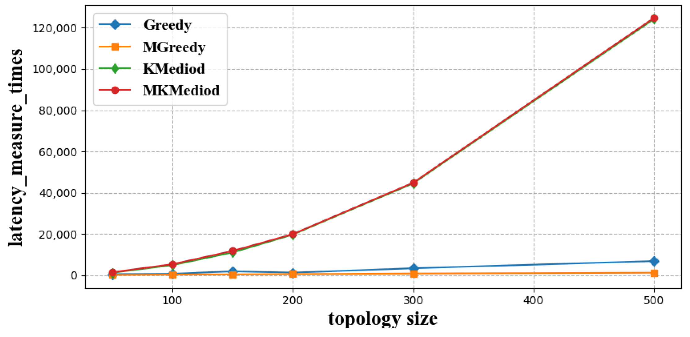
  • Greedy algorithm [32]: This algorithm traverses each child node, uses the traversed child nodes to form an index neighbor group and tries to pull the rest of the child nodes into the group, this procedure is performed recursively until every child node resides in an index neighbor group.
  • Modified Greedy algorithm: Different from the Greedy algorithm, this algorithm firstly sorts the child nodes by latency to the master node, and then greedily constructs index neighbor groups in the same manner with the Greedy algorithm in decent order of latency to the master node.
  • K-Mediod algorithm [33]: Like our proposed MK-Mediod algorithm, this algorithm clusters the child nodes according to their latency to each other, and validates whether the clustering results meet the latency constraints defined by index neighbor groups. Clustering number increases one by one until a feasible resolution is found.

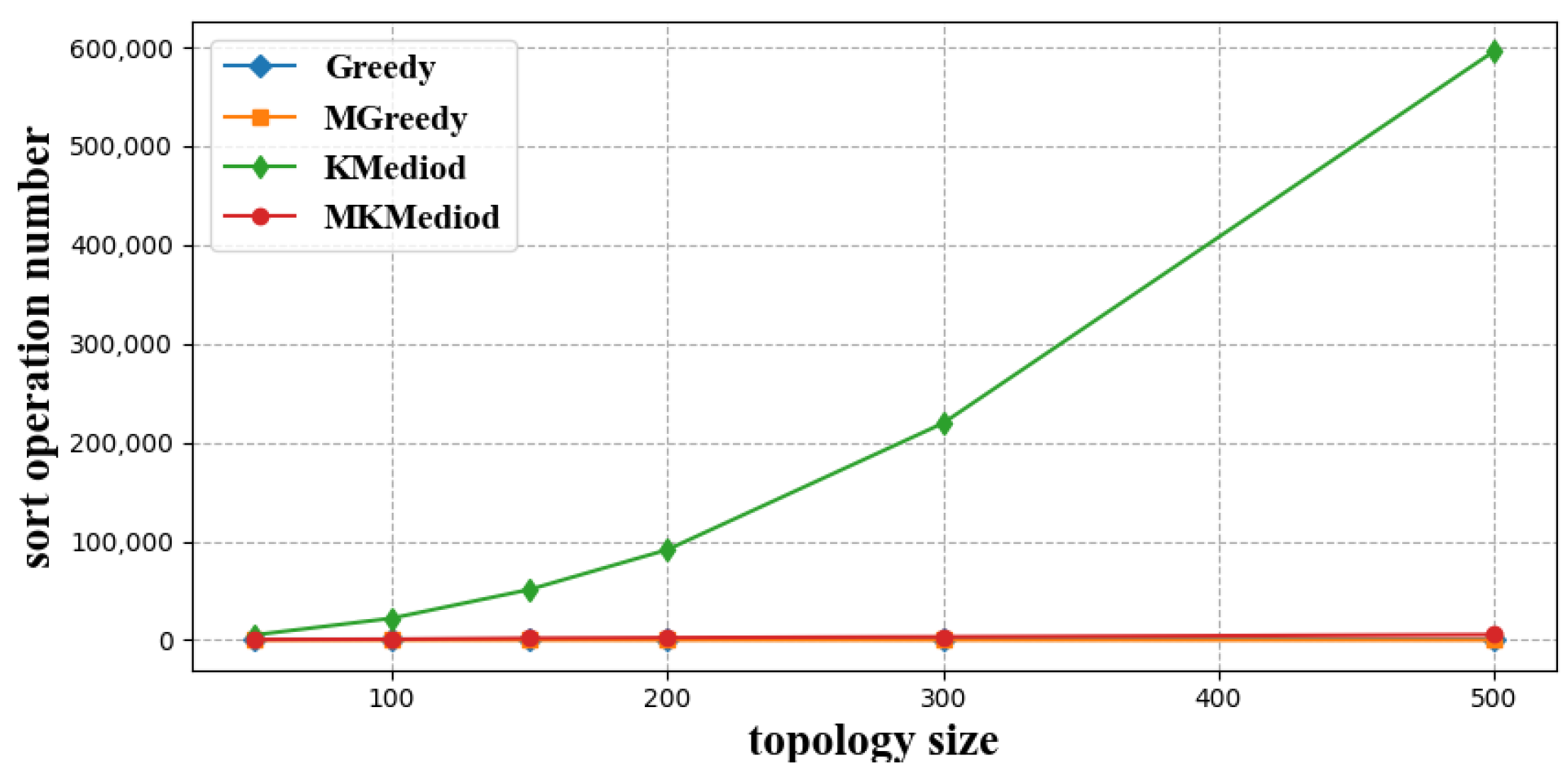
3.2.1. Latency Measure Times

In order to compare the latency measurement cost of each algorithm, we counted the number of latency measurements of different index neighbor construction algorithms at different network sizes, and simulation results are shown in Figure 4.
As shown in Figure 4, the MK-Mediod algorithm and K-Mediod algorithm have the same latency measure times for each topology size—they require the most latency measurement cost. The Greedy algorithm and MGreedy algorithm have less latency measure times, and the MGreedy algorithm requires the least cost of latency measurements.
The reason for this is that the clustering algorithm needs to perform latency measurements in each round with new cluster centers until the clustering algorithm obtains converged results. Thus, these two clustering algorithms need to measure the latency between every node to each other. The Greedy algorithm also traverses each resolution node, but the nodes traversed will definitely find their index neighbors and index neighbor groups, so there is no case of discarding the original traversal results and re-traversing, so the number of latency measurements required is less. The MGreedy algorithm requires fewer latency measurements because it firstly selects the children nodes nearest to the master node for traversal, and these nodes have a higher probability of being selected as index neighbors and building larger index neighbor groups.
Furthermore, we found that latency measurement times of various index neighbor construction algorithms increases with increased network size, with MK-Mediod and K-Mediod algorithms showing a particularly significant increase in latency measurement times, while the other two greedy algorithms do not show a significant increase in the latency measurement times.

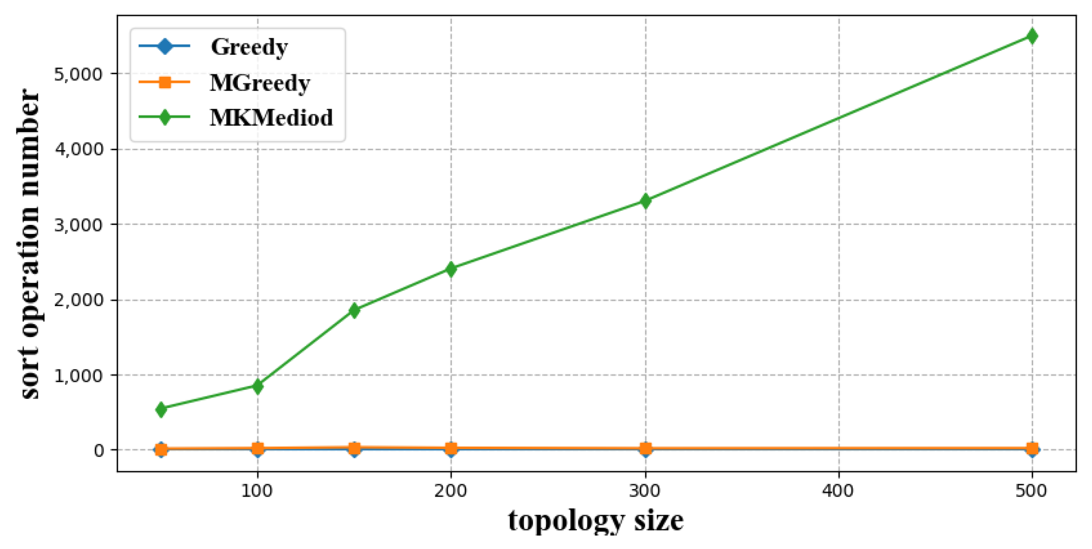
3.2.2. Computation Cost

Each algorithm involves multiple sorting operations, and the sorting operations are computationally intensive. We counted the number of sorting operation in different index neighbor construction algorithms at different network sizes, which reflects the computational consumption of each algorithm. The simulation results are shown in Figure 5 and Figure 6, where the former figure shows the number of sorting operations performed in four index neighbor construction algorithms, Greedy, MGreedy, K-Mediod, and MK-Mediod, at different node sizes, and the latter figure shows detailed comparasion among Greedy, MGreedy, and MK-Mediod.
As shown in Figure 5 and Figure 6, the K-Mediod algorithm involves the most number of sort operations; MK-Mediod and MGreedy algorithms were less, and Greedy algorithm was the least. The sort operation number in the MK-Mediod was 3.73% of that in K-Mediod.
The reason for this is that the Greedy algorithm greedily traverses each resolution node without sort operations, so the sort operations in this algorithm are always 0. The MGreedy algorithm sorts the children at the beginning of the traversal based on the latency of each child node to the master node, so the MGreedy algorithm performs one sort operation. Both clustering methods sort the l a t values of each node at each round of cluster center update operation, while the MK-Mediod algorithm performs fewer sort operations than the K-Mediod algorithm because it finish the construction with fewer rounds.

3.3. Collaborative Storage and Resolution

To verify the impact on total system storage when using different index neighbor structures for inter-layer collaborative storage, we adopt the simplest static load balancing strategy; the master node stores a certain percentage of mapping records to index neighbors, and we compare the increase in total system storage load after collaborative storage as well as the average service latency and maximum service latency during collaborative resolution.
During the collaborative storage process, this experiment generates n u m b e r o f s y s t e m n o d e s 100 mapping records and randomly selects level-2 resolution nodes for registration, and the registration is then passed to the master node afterwards. During the collaborative resolution process, this experiment take 20% of the mapping records of the master node for co-storage, and resolves all mapping records on the master node from randomly selected users.

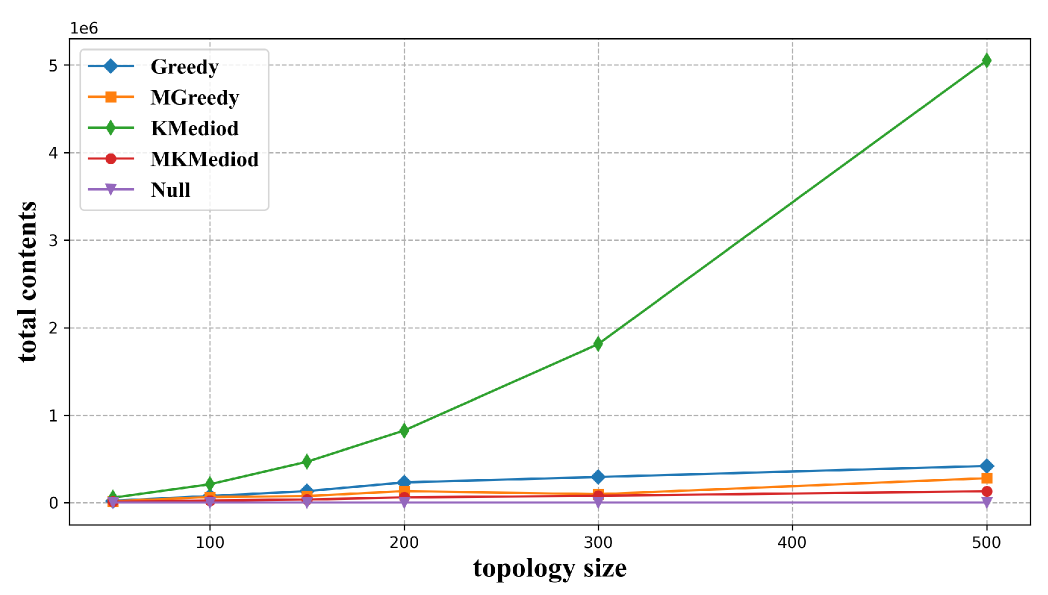
3.3.1. Total Storage Load

(a)
Impact of number of resolution nodes
We set the number of resolution nodes as 50/100/150/200/300/500, and construct index neighbor structure with Greedy, MGreedy, K-Mediod, and MK-Mediod algorithm. Afterwards, the constructed index neighbor structure is used for collaborative mapping records storage. Here, we take 20% mapping records from the master node for co-storage, and compare the total storage load of the system. The situation without co-storage is used as a benchmark for comparison.
As seen from Figure 7, the K-Mediod algorithm corresponds to the greatest total storage load, the Greedy algorithm is the second, and the MK-Mediod algorithm corresponds to the least total storage load.
The reason is that, in the collaborative storage method based on index neighbor structure, each index neighbor group will be assigned one copy of the mapping records to be co-stored for the purpose that users of each index neighbor group could resolve these mapping records within a determined service latency. If the number of index neighbor groups is too large, it will cause a large increase in the total storage load. K-Mediod algorithm does not consider the latency to the master node in the clustering process, so the elected cluster center does not represent the best node position, and the clustering effect is not ideal. In one round of the cycle, the number of index neighbor groups needs to be increased as long as one clustering group does not pass the following validation process, so the number of index neighbor groups generated by K-Mediod algorithm is the largest, and the corresponding total storage load is also the largest. The two greedy algorithms build index neighbor groups in a greedy manner, and the subsequent index neighbor group constructing process will not affect the previous constructed index neighbor groups, so the number of index neighbor groups built is less than that of the K-Mediod algorithm, which corresponds to less total storage load. The MGreedy algorithm firstly selects nodes close to the master node as an index neighbor, and the l a t e n c y ( i n d e x N e i k , R N i + 1 t ) part in Equation(6) is then more easily fulfilled, so these nodes have a higher probability of building larger index neighbor groups, which will result in fewer index neighbor groups, and correspondingly, less total storage load. In the clustering process, the MK-Mediod algorithm considers not only the latency between child nodes, but also the latency to the master node, so the clustering results are more easily passed in the following validation procedure. The construction result is the best of the four algorithms, which means the lest number of index neighbor groups and the smallest total storage load.
(b)
Impact of numbers of mapping records for co-storage
We set the resolution system node size as 500. Four algorithms of Greedy, MGreedy, K-Mediod, and MK-Mediod were used to construct index neighbors, and the constructed index neighbor structure was used for collaborative mapping records storage. Here, the ratio of mapping records on the master node for co-storage was set to 2%, 5%, 10%, and 20%. We compared total storage load in these situations to explore the impact of numbers of mapping records for co-storage. Situation without co-storage was used as a benchmark for comparison.
As seen from Table 2, the total storage load corresponding to the MK-Mediod algorithm was the smallest and the total storage load corresponding to the K-Mediod algorithm was the largest for different co-storage mapping record ratios. The total storage load increase in the MK-Mediod algorithm was 57.1% of the MGreedy algorithm, 8.1% of the Greedy algorithm, and 0.8% of the K-Mediod algorithm.
Both the table and the above figure reflect the difference in the number of index neighbor groups constructed by these four algorithms. The K-Mediod algorithm constructs the largest number of index neighbor groups, which results in the largest total system storage and the largest increase in total storage load. The MK-Mediod algorithm, conversely, construct the smallest number of index neighbor groups, and certainly, the smallest increase in total storage load. Total storage load increases as the ratio number increases, but the comparison of the total storage load for the four algorithms stays stable regardless of the value of the ratio.

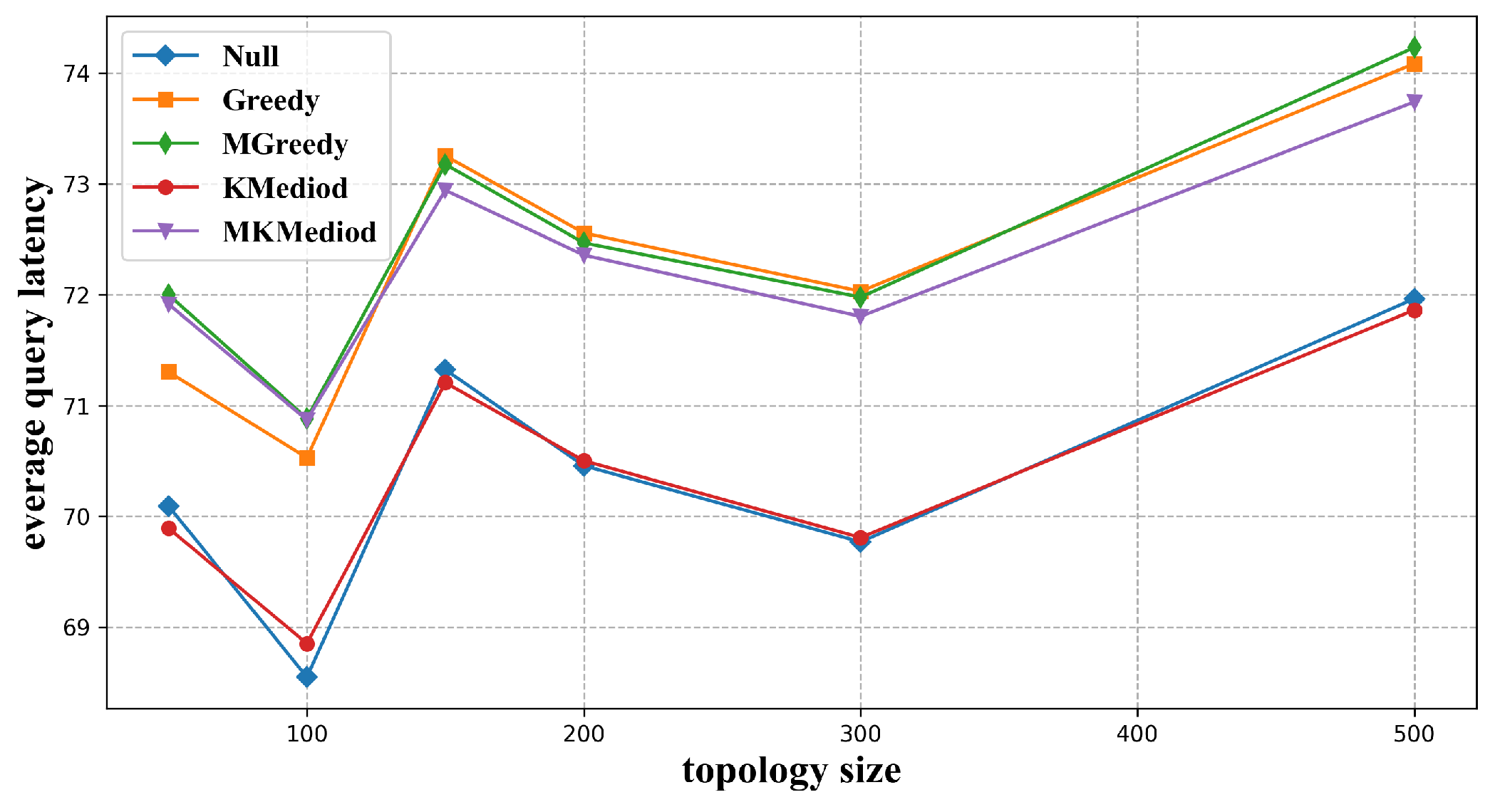
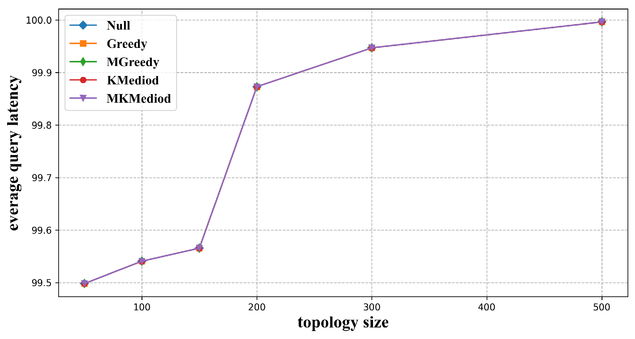
3.3.2. Average Service Latency and Maximum Service Latency

Figure 8 compares the average resolution service latency when the constructed index neighbor is used for collaborative resolution. The situation without collaborative resolution was used as a benchmark for comparison.
As shown in Figure 8, the average service latency was smallest when no index neighbor structure was used, or when index neighbor structure constructed by K-Mediod algorithm was used. The average service latency with index neighbor structure constructed by Greedy, MGreedy, and MK-Mediod algorithms does not differ significantly when the system size is small, while the average service latency corresponding to the MK-Mediod algorithm was significantly smaller when the node size increased.
The reason is that, when index neighbor structure is not used for co-resolution, users’ resolution requests are directly responded by the master node without any redirection, the service latency is the smallest. The number of index neighbor groups constructed by the K-Mediod algorithm was the largest. When the system node size was set to 500, the K-Mediod algorithm will construct 500 index neighbor groups, which means every resolution node in level 2 will be one index neighbor group by itself. In this situation, for a specific user, u i , if its corresponding resolution node in level 2 is R N i + 1 , when the resolution request send by u i cannot be fulfilled at the master node, it will be redirected to R N i + 1 , which is the nearest resolution node to u i in level 2, and certainly, this structure will result in a smaller service latency. For MK-Mediod, MGreedy, and Greedy algorithms, in index neighbor groups constructed by the MK-Mediod algorithm, nodes in one group are closer to each other, which means a user could find a closer index neighbor for collaborative resolution, and the other two greedy algorithms do not take this into account, thus the service latency corresponding to MK-Mediod algorithm is smaller.
Meanwhile, we compared the maximum service latency when these constructed index neighbors were used for a collaborative resolution. As shown in Figure 9, the maximum service latency distributes from 99.5 ms to 100 ms, and the latency increased with topology size.
The reason is that, for the same LNMRS topology, the longest forwarding path from the master node to its users will always be found in any index neighbor structure as long as the number of resolution requests is large enough. LNMRS topologies of different sizes are randomly constructed according to the same latency rules, so the maximum latency from the users to the master node is slightly different for different topologies, and the larger the topology size, the more likely it is to traverse to a larger latency value.

4. Conclusions

In this paper, we address the problem of unbalanced storage load between layers in LNMRS by co-store mapping items of a higher level resolution node to lower level resolution nodes. We construct an index neighbor structure to find nodes for inter-layer collaborative storage, and model the index neighbor construction problem as a combinatorial optimization problem. We propose an index neighbor structure construction method based on our proposed MK-Mediod algorithm. Based on the constructed index neighbor structure, this paper propose an inter-layer collaborative storage and resolution method that satisfies the deterministic service delay feature.
We compare the cost and effect of the index neighbor structure-based collaborative storage and resolution method in this paper with three other index neighbor construction algorithms. The results show that to co-store the same number of mapping records for the master node, the increase of total storage load is less when index neighbor structure constructed in this paper is used for collaborative storage, which is is 57.1% of that in the MGreedy algorithm, 8.1% of the Greedy algorithm, and 0.8% of the K-Mediod algorithm. The computation overhead in the construction procedure of our algorithm is only 3.73% of that in the original K-Mediod algorithm, and the latency measurement overhead is the same as that in the original K-Mediod algorithm. Although Greedy and MGreedy algorithms have less latency measurement and computational overhead, their corresponding total storage load increase is too large in the collaborative storage procedure. It is worth noting that no matter which index neighbor structure is used for collaborative resolution, the deterministic service latency constraint of the master node is still sustained. Experiment results show that our proposed index neighbor structure-based collaborative storage and resolution method could achieve collaborate storage with less computation and storage cost compared with other algorithms. However, the proposed MK-Mediod algorithm has a limit that it must be executed centrally, which means a bad scalability.
Future work can be considered in the following two aspects: First, the greedy algorithm can be executed distributively at each child node. However, the K-Mediod algorithm and the modified algorithm based on it need a complete latency measurement result for execution. How to perform the MK-Mediod algorithm distributively, supporting better scalability, should be considered. Second, we select one index neighbor in each index neighbor group in this paper, but there might be more than one node meeting the constraints of the index neighbor. It should be considered to maintain, as much as possible, the index neighbors in one index neighbor group for the sake of storage load balancing.

Author Contributions

Conceptualization, Y.L. (Yanxia Li) and Y.L. (Yang Li); methodology, Y.L. (Yanxia Li) and Y.L. (Yang Li); software, Y.L. (Yanxia Li); writing—original draft preparation, Y.L. (Yanxia Li); writing—review and editing, Y.L. (Yanxia Li) and Y.L. (Yang Li); supervision, Y.L. (Yang Li); project administration, Y.L. (Yang Li); funding acquisition, Y.L. (Yang Li). All authors have read and agreed to the published version of the manuscript.

Funding

This work was funded by the Strategic Leadership Project of Chinese Academy of Sciences: SEANET Technology Standardization Research System Development (Project No. XDC02070100).

Acknowledgments

We would like to express our gratitude to Jinlin Wang and Xiao Chen for their meaningful support of this work.

Conflicts of Interest

The authors declare no conflict of interest.

References

  1. Huang, T.; Liu, J.; Wang, S.; Zhang, C.; Liu, R.J. Survey of the future network technology and trend. J. Commun. 2021, 42, 130–150. [Google Scholar]
  2. Ravindran, R.; Suthar, P.; Chakraborti, A.; Amin, S.O.; Azgin, A.; Wang, G. Deploying ICN in 3GPP’s 5G NextGen Core Architecture. In Proceedings of the 2018 IEEE 5G World Forum (5GWF), Santa Clara, CA, USA, 9–11 July 2018; pp. 26–32. [Google Scholar]
  3. Menth, M.; Hartmann, M.; Klein, D. Global locator, local locator, and identifier split (GLI-Split). Future Internet 2013, 5, 67–94. [Google Scholar] [CrossRef]
  4. Albalawi, A.; Garcia-Luna-Aceves, J.J. Named-Data Transport: An End-to-End Approach for an Information-Centric IP Internet. In Proceedings of the 7th ACM Conference on Information-Centric Networking, Online, 29 September–1 October 2020; pp. 136–148. [Google Scholar]
  5. Shannigrahi, S.; Fan, C.; Partridge, C. What’s in a Name?: Naming Big Science Data in Named Data Networking. In Proceedings of the 7th ACM Conference on Information-Centric Networking, Online, 29 September–1 October 2020; pp. 77–88. [Google Scholar]
  6. Handley, M. Why the Internet only just works. BT Technol. J. 2006, 24, 119–129. [Google Scholar] [CrossRef]
  7. Feldmann, A. Internet clean-slate design: What and why? ACM SIGCOMM Comput. Commun. Rev. 2007, 37, 59–64. [Google Scholar] [CrossRef]
  8. Parvez, I.; Rahmati, A.; Guvenc, I.; Sarwat, A.I.; Dai, H. A survey on low latency towards 5G: RAN, core network and caching solutions. IEEE Commun. Surv. Tutor. 2018, 20, 3098–3130. [Google Scholar] [CrossRef]
  9. Nasrallah, A.; Thyagaturu, A.S.; Alharbi, Z.; Wang, C.; Shao, X.; Reisslein, M.; ElBakoury, H. Ultra-low latency (ULL) networks: The IEEE TSN and IETF DetNet standards and related 5G ULL research. IEEE Commun. Surv. Tutorials 2019, 21, 88–145. [Google Scholar] [CrossRef]
  10. ITU Web Site. Available online: https://www.itu.int/en/ITU-T/focusgroups/net2030/Documents/White_Paper.pdf (accessed on 15 October 2022).
  11. Liu, H.; Azhandeh, K.; de Foy, X.; Gazda, R. A comparative study of name resolution and routing mechanisms in information-centric networks. Digit. Commun. Netw. 2019, 5, 69–75. [Google Scholar] [CrossRef]
  12. Barakabitze, A.A.; Xiaoheng, T.; Tan, G. A Survey on Naming, Name Resolution and Data Routing in Information Centric Networking (ICN). Int. J. Adv. Res. Comput. Commun. Eng. 2014, 3, 8322–8330. [Google Scholar] [CrossRef]
  13. Xylomenos, G.; Ververidis, C.N.; Siris, V.A.; Fotiou, N.; Tsilopoulos, C.; Vasilakos, X.; Katsaros, K.V.; Polyzos, G.C. A survey of information-centric networking research. IEEE Commun. Surv. Tutor. 2014, 16, 1024–1049. [Google Scholar] [CrossRef]
  14. Mathy, L.; Iannone, L. LISP-DHT: Towards a DHT to map identifiers onto locators. In Proceedings of the 2008 ACM CoNEXT Conference—4th International Conference on Emerging Networking EXperiments and Technologies, Madrid, Spain, 9–12 December 2008; pp. 1–6. [Google Scholar]
  15. Stoica, I.; Morris, R.; Karger, D.; Kaashoek, M.F.; Balakrishnan, H. Chord: A scalable peer-to-peer lookup service for internet applications. ACM SIGCOMM Comput. Commun. Rev. 2001, 31, 149–160. [Google Scholar] [CrossRef]
  16. Wang, P.; Lan, J.; Hu, Y.; Chen, S. Towards locality-aware DHT for fast mapping service in future Internet. Comput. Commun. 2015, 66, 14–24. [Google Scholar] [CrossRef]
  17. Hong, J.; Chun, W.; Jung, H. Demonstrating a scalable name resolution system for information-centric networking. In Proceedings of the ICN 2015—2nd International Conference on Information-Centric Networking, San Francisco, CA, USA, 30 September–2 October 2015; pp. 221–222. [Google Scholar]
  18. Wang, J.; Chen, G.; You, J.; Sun, P. SEANet: Architecture and Technologies of an On-site, Elastic, Autonomous Network. Netw. New Media 2020, 6, 1–8. [Google Scholar]
  19. Xie, W.; You, J.; Wang, J. A Tree Structure Protocol for Hierarchical Deterministic Latency Name Resolution System. Electronics 2022, 11, 2425. [Google Scholar] [CrossRef]
  20. TU-T Y. ICN-NMR Framework of Locally Enhanced Name Mapping and Resolution for Information Centric Networking in IMT-2020. Available online: https://www.itu.int/md/T17-SG13-C-1319/ (accessed on 15 October 2022).
  21. ITU Web Site. Requirements and Capabilities of Name Mapping and Resolution for Information Centric Networking in IMT-2020. Available online: https://www.itu.int/itu-t/recommendations/rec.aspx?rec=13890 (accessed on 15 October 2022).
  22. Luo, H.; Qin, Y.; Zhang, H. A DHT-based identifier-to-locator mapping approach for a scalable Internet. IEEE Trans. Parallel Distrib. Syst. 2009, 20, 1790–1802. [Google Scholar]
  23. Fuller, V.; Farinacci, D.; Meyer, D. LISP Alternative Topology (LISP+ALT). Available online: http://tools.ietf.org/id/draft-ietf-lisp-alt-10.txt (accessed on 15 October 2022).
  24. Dannewitz, C.; Kutscher, D.; Ohlman, B.; Farrell, S.; Ahlgren, B.; Karl, H. Network of information (NetInf)-An information-centric networking architecture. Comput. Commun. 2013, 36, 721–735. [Google Scholar] [CrossRef]
  25. Rajahalme, J.; Särelä, M.; Visala, K.; Riihijärvi, J. On name-based inter-domain routing. Comput. Netw. 2011, 55, 975–986. [Google Scholar] [CrossRef]
  26. Koponen, T.; Chawla, M.; Chun, B.G.; Ermolinskiy, A.; Kim, K.H.; Shenker, S.; Stoica, I. A data-oriented (and Beyond) network architecture. Comput. Commun. Rev. 2007, 37, 181–192. [Google Scholar] [CrossRef]
  27. Louati, W.; Ben-Ameur, W.; Zeghlache, D. A bottleneck-free tree-based name resolution system for Information-Centric Networking. Comput. Netw. 2015, 91, 341–355. [Google Scholar] [CrossRef]
  28. D’Ambrosio, M.; Dannewitz, C.; Karl, H.; Vercellone, V. MDHT: A hierarchical name resolution service for information-centric networks. In Proceedings of the ACM SIGCOMM Workshop on Information-Centric Networking, Toronto, ON, Canada, 15–19 August 2011. [Google Scholar]
  29. Dannewitz, C.; D’Ambrosio, M.; Vercellone, V. Hierarchical DHT-based name resolution for information-centric networks. Comput. Commun. 2013, 36, 736–749. [Google Scholar] [CrossRef]
  30. Li, Y.; Wang, J.; Sun, P.; Jiaqi, L.I. System for Providing Exact Communication Delay Guarantee of Request Response for Distributed Service. CN Patent 201910897838.8, 23 September 2021. [Google Scholar]
  31. Li, J.; Sheng, Y.; Deng, H. Two Optimization Algorithms for Name-Resolution Server Placement in Information-Centric Networking. Appl. Sci. 2020, 10, 3588. [Google Scholar] [CrossRef]
  32. Orenshtein, T.; Shinkar, I. Greedy Random Walk. Comb. Probab. Comput. 2014, 23, 269–289. [Google Scholar] [CrossRef] [Green Version]
  33. Chu, S.C.; Roddick, J.; Pan, J.S. A comparative study and extensions to k-medoids algorithms. In Proceedings of the Fifth International Conference on Optimization: Techniques and Applications, Hong Kong, China, 15–17 December 2001. [Google Scholar]
Figure 1. Service area inclusive relationship among name resolution nodes in higher and lower levels of LNMRS. A resolution node in higher levels maintains a larger service area, which is consisted of the service areas of its children nodes.
Futureinternet 15 00074 g001
Figure 2. An index neighbor structure example, which shows the relationships among master node, index neighbor node, and users of the master node. In the service scenario involving index neighbor, a resolution request is sent from a user of the master node to the master node, and then redirected to the index neighbor. The resolution response is then sent by the index neighbor to the user.
Futureinternet 15 00074 g002
Figure 3. LNMRS model with two levels, with a master node and two index neighbor groups.
Futureinternet 15 00074 g003
Figure 4. Latency measure times of each algorithm with different network sizes.
Futureinternet 15 00074 g004
Figure 5. Number of sort operations of each algorithm with different network sizes.
Futureinternet 15 00074 g005
Figure 6. Number of sort operations of each algorithm with different network sizes—detailed comparision.
Futureinternet 15 00074 g006
Figure 7. Total storage load of each algorithm with different network sizes.
Futureinternet 15 00074 g007
Figure 8. Average resolution service latency of each algorithm with different network sizes.
Futureinternet 15 00074 g008
Figure 9. Maximum resolution latency of each algorithm with different network sizes.
Futureinternet 15 00074 g009
Table 1. Evaluation setting.
ParameterValue
Number of resolution nodes50/100/150/200/300/500
Deterministic latency parameters50 ms, 25 ms
Latency scope from master node to nodes in level 2[0.5 ms, 25 ms)
Latency scope among child nodes[5 ms, 30 ms)
Total number of contents100*(number of resolution nodes)
Ratio of contents to be co-stored2%/5%/10%/20%
Contents for resolutionall of the contents on master node
Latency scope from master node to users[25 ms, 50 ms)
Latency scope from resolution nodes in level 2 to users[0.5 ms, 25 ms)
Table 2. Total storage load at different co-storage ratios.
2%5%10%20%
Null100,000100,000100,000100,000
MK-Mediod108,000120,000140,000180,000
MGreedy114,000135,000170,000240,000
Greedy198,000255,000590,0001,080,000
K-Mediod1,100,0002,600,0005,100,00010,100,000
Disclaimer/Publisher’s Note: The statements, opinions and data contained in all publications are solely those of the individual author(s) and contributor(s) and not of MDPI and/or the editor(s). MDPI and/or the editor(s) disclaim responsibility for any injury to people or property resulting from any ideas, methods, instructions or products referred to in the content.

