
Human–Machine Interaction through Advanced Haptic Sensors: A Piezoelectric Sensory Glove with Edge Machine Learning for Gesture and Object Recognition
 ,
,
Abstract
:1. Introduction
- Analysis of the main applications of the haptic feedback technologies, providing a general discussion of the physiological mechanism of the haptic feedback, as well as a general classification of modern haptic interfaces.
- A comprehensive overview of wearable interfaces for haptic feedback, providing comparative analysis and insights about the discussed systems and defining features and architectures of the next generation of haptic devices.
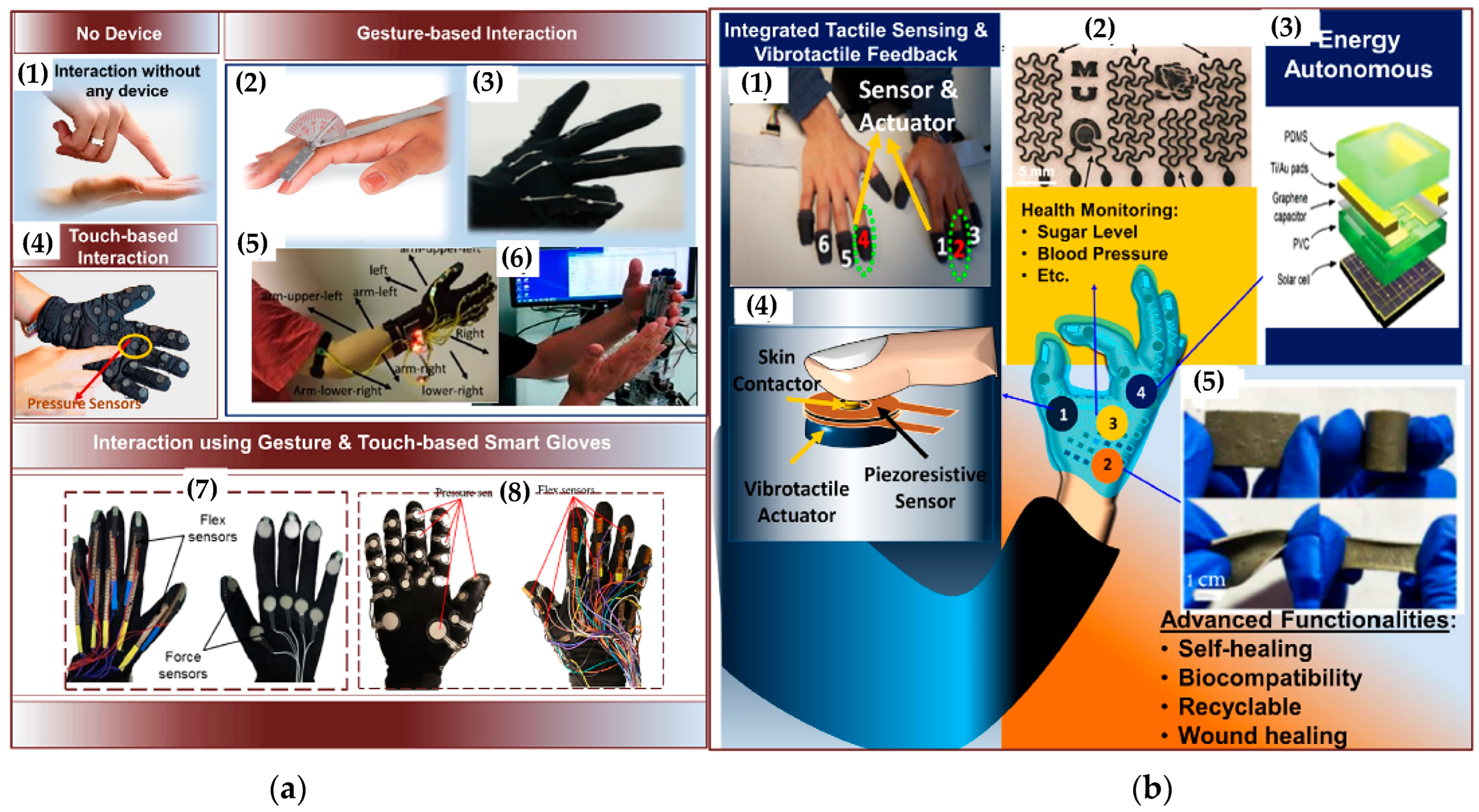
- A survey of recent sensing systems for haptic interfaces in the form of smart gloves for monitoring hand and finger movements and providing biofeedback to the user.
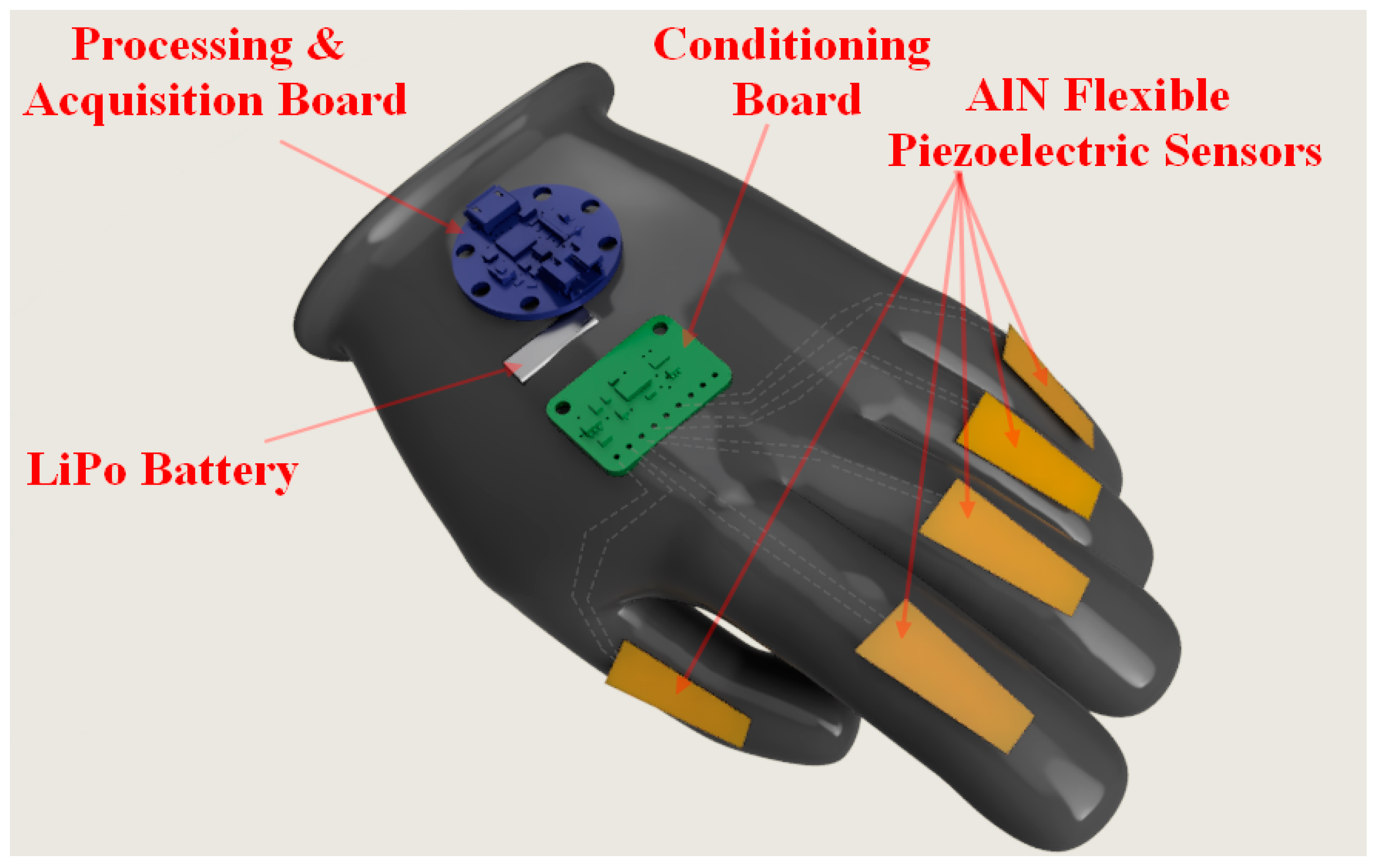
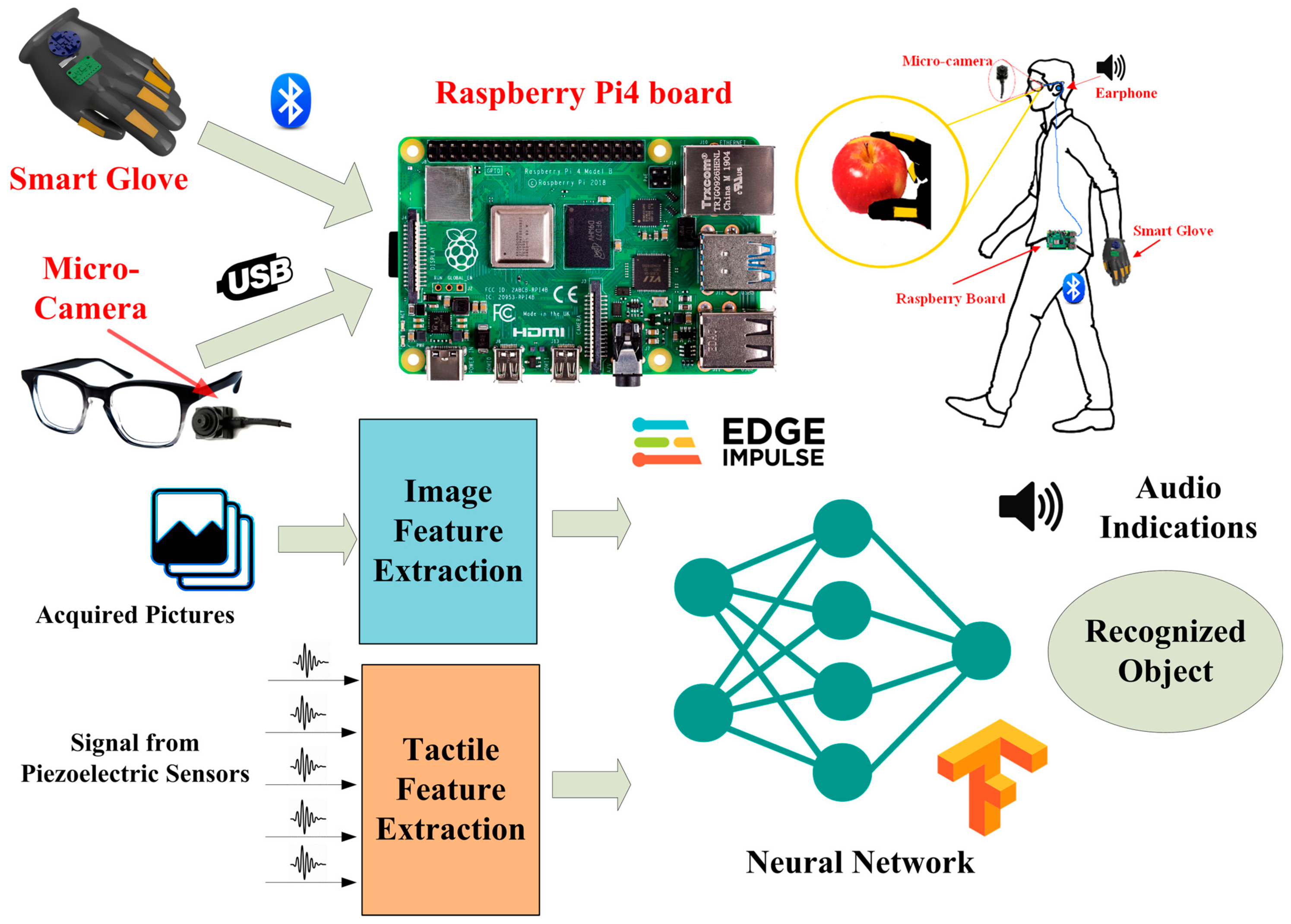
- A novel smart glove based on ultrathin AlN sensors for detecting hand motions. Additionally, the architecture of a hybrid visual-tactile recognition system based on the developed glove is introduced. Finally, the design and testing of the electronic conditioning section for handling signals generated by piezoelectric sensors are reported.
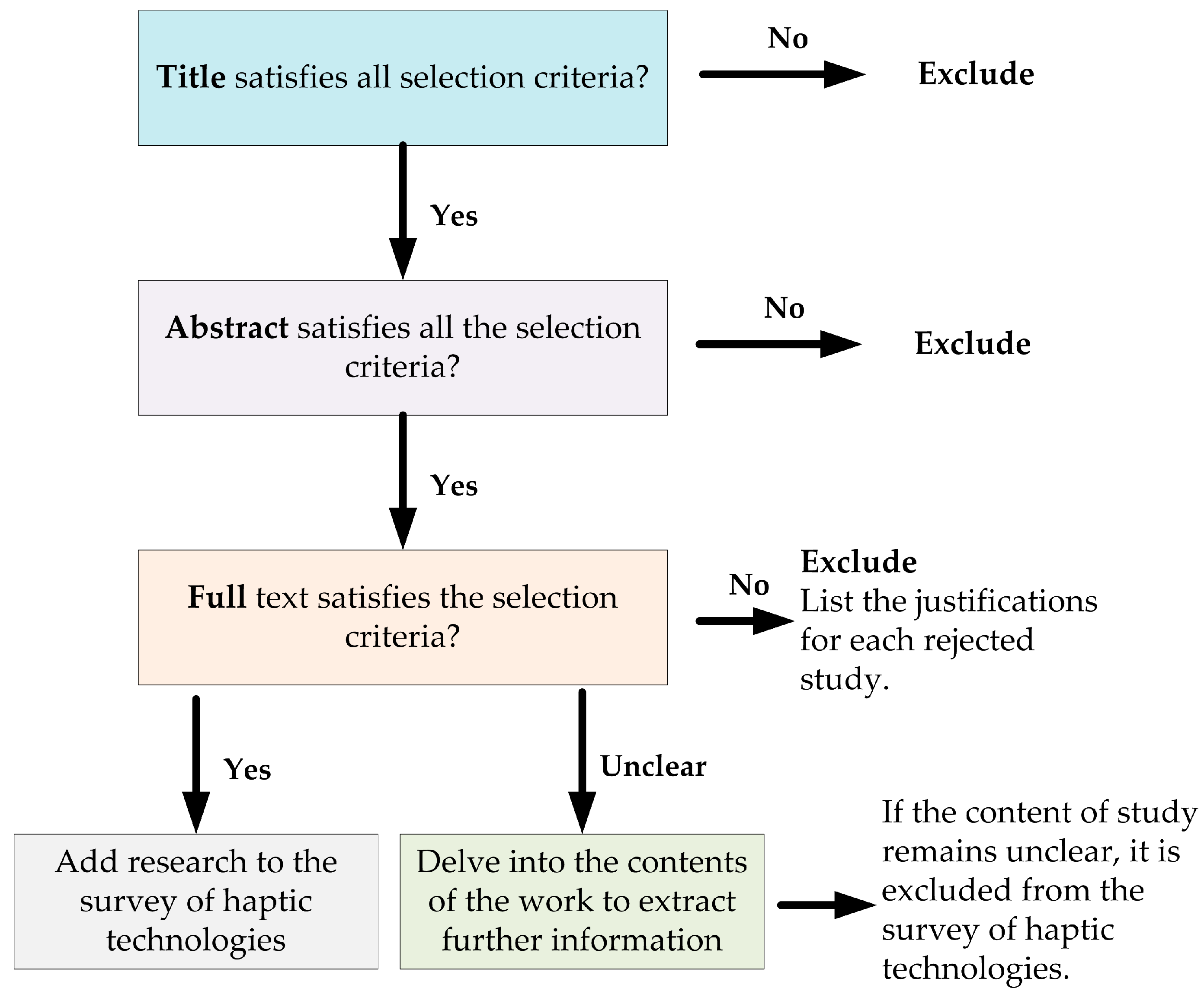
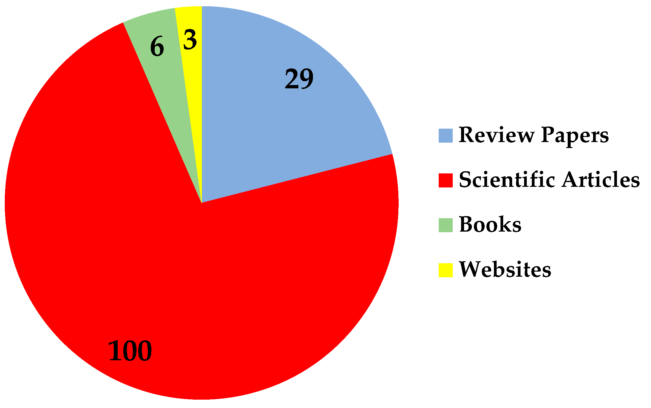
Selection and Exclusion Criteria for Performing the Survey of Haptic Technologies
2. Problem Definition and Application of Haptic Feedback Technologies
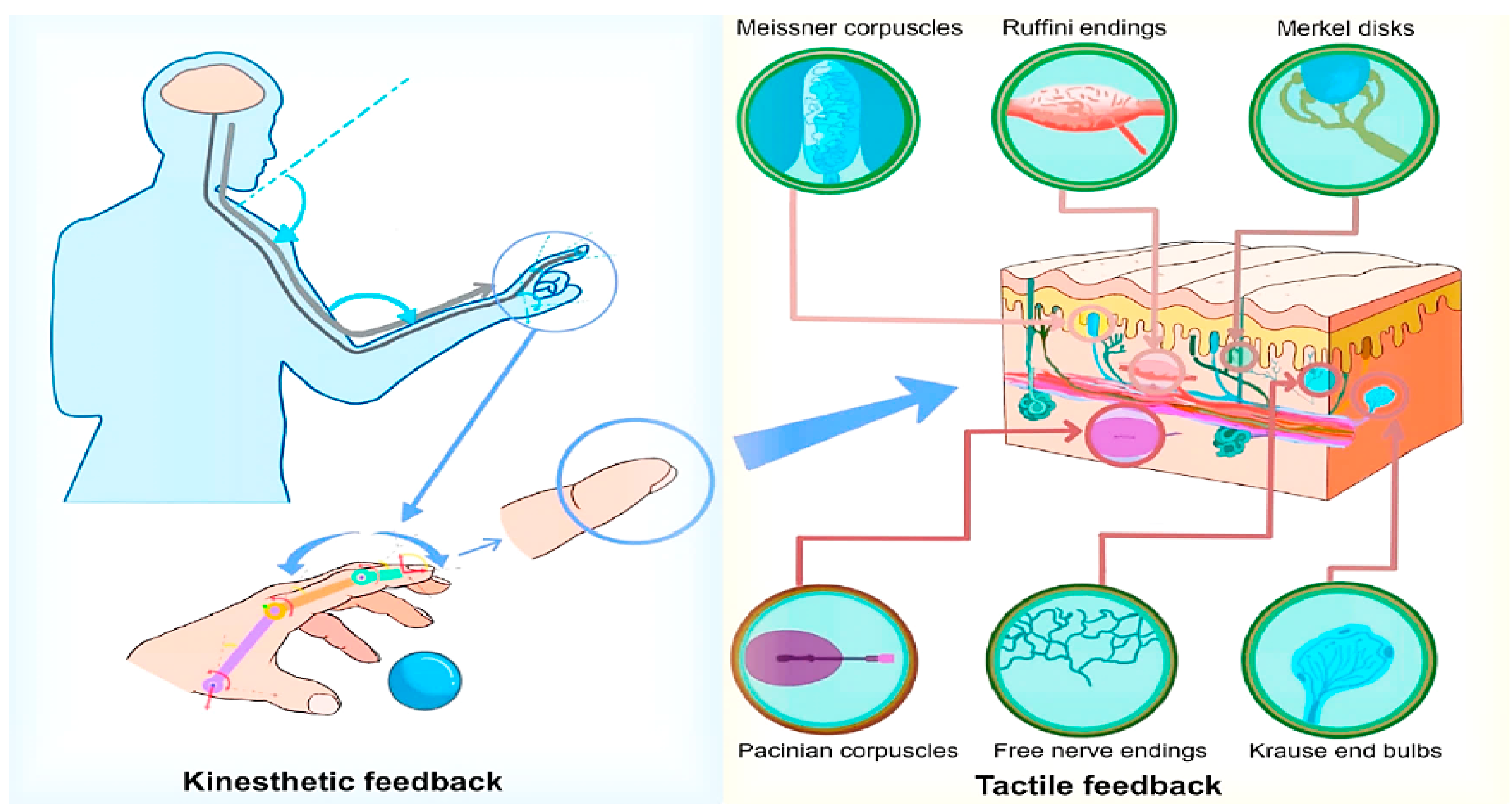
2.1. Haptic Feedback’s Physiological Mechanisms
2.2. Haptic Feedback
3. General Classification of Modern Haptic Interfaces
- Force-based tactile devices;
- Thermal-based tactile devices;
- Nerve stimulation tactile devices.
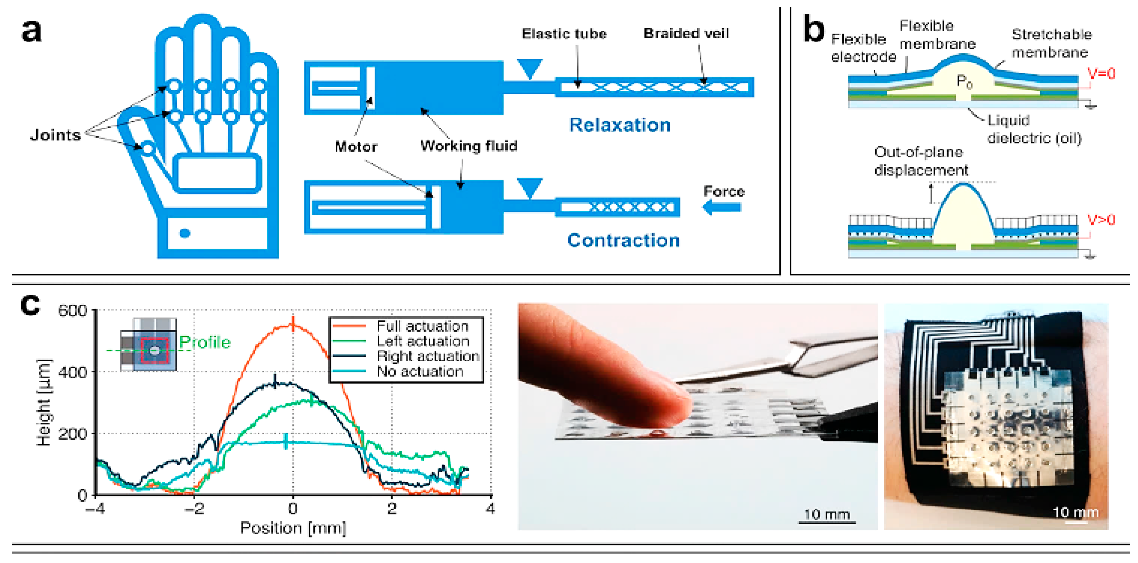
3.1. Hydraulic Haptic Interfaces
3.2. Pneumatic Haptic Interfaces
- Cheap and high responsivity;
- Compact and lightweight systems;
- No constraints on output size or design;
- No recirculation lines, unlike a hydraulic system;
- Simple pressure and speed adjustment
- Appropriate for a spotless workplace;
- High power-to-weight ratio;
- A safe usage.
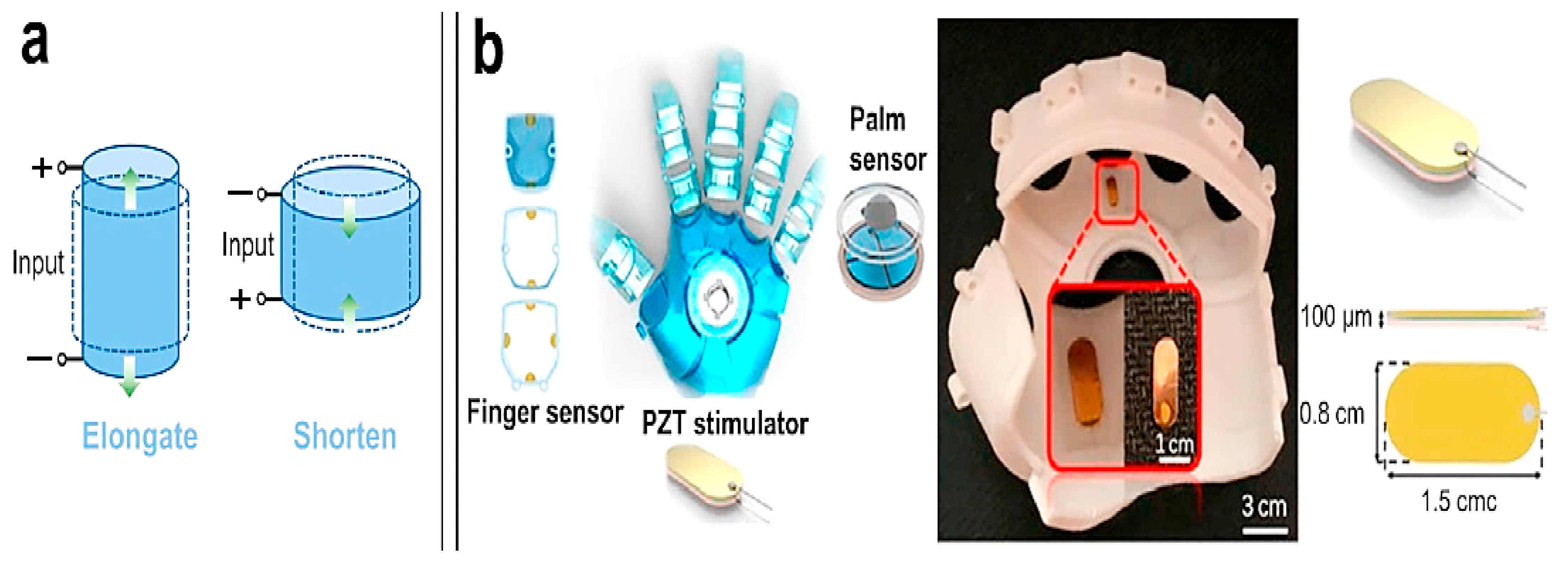
3.3. Piezoelectric Haptic Interfaces
3.4. Electromagnetic Haptic Interfaces
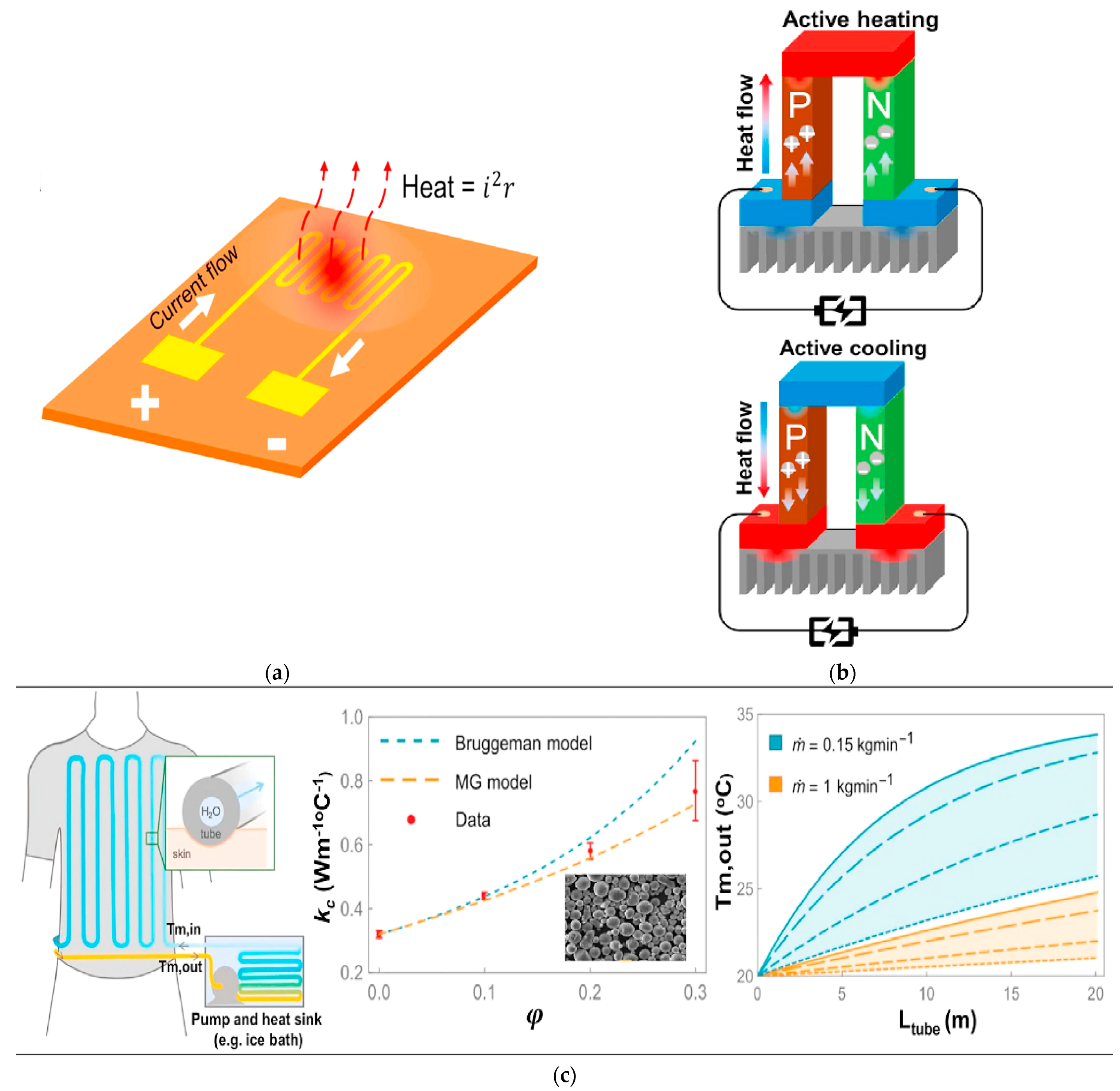
3.5. Thermal-Based Haptic Interfaces
3.5.1. Thermoelectric Haptic Interfaces
3.5.2. Microfluidic and Other Thermal-Based Haptic Interfaces
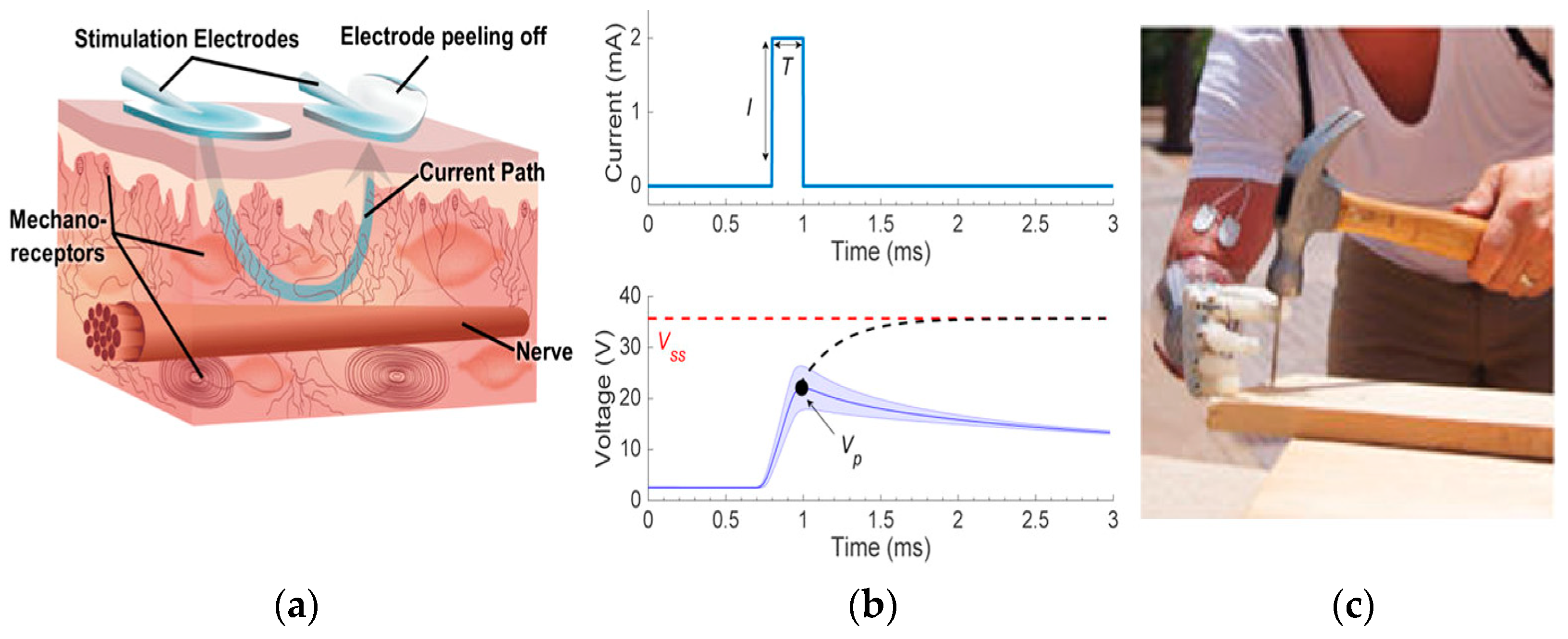
3.6. Nerve Stimulation-Based Haptic Interfaces
3.7. Multi-Mode Integrated Haptic Interfaces
4. Overview of Wearable Interface for Providing Haptic Feedback
5. Survey of Sensing Systems for Haptic Interface
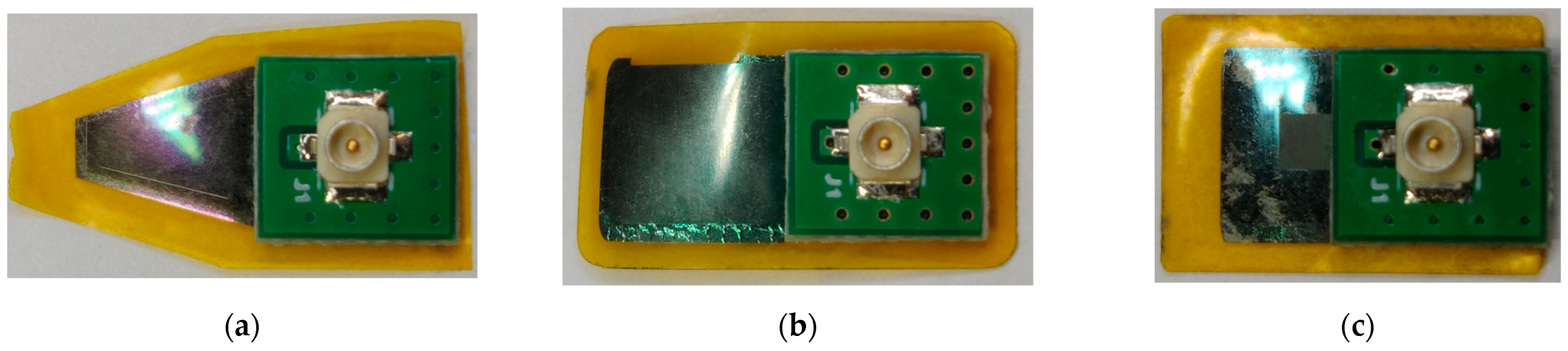
6. Designed Architecture of the Smart Sensory Glove Based on AlN-Based Sensors
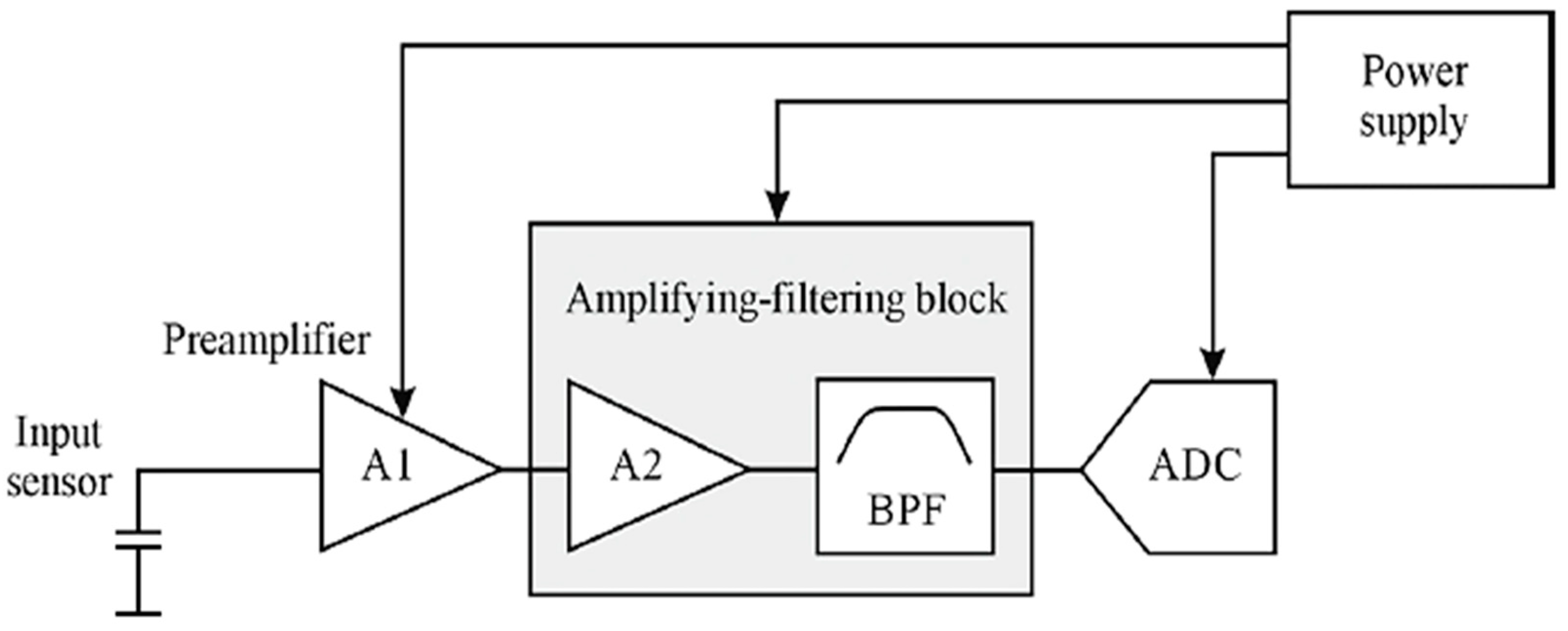
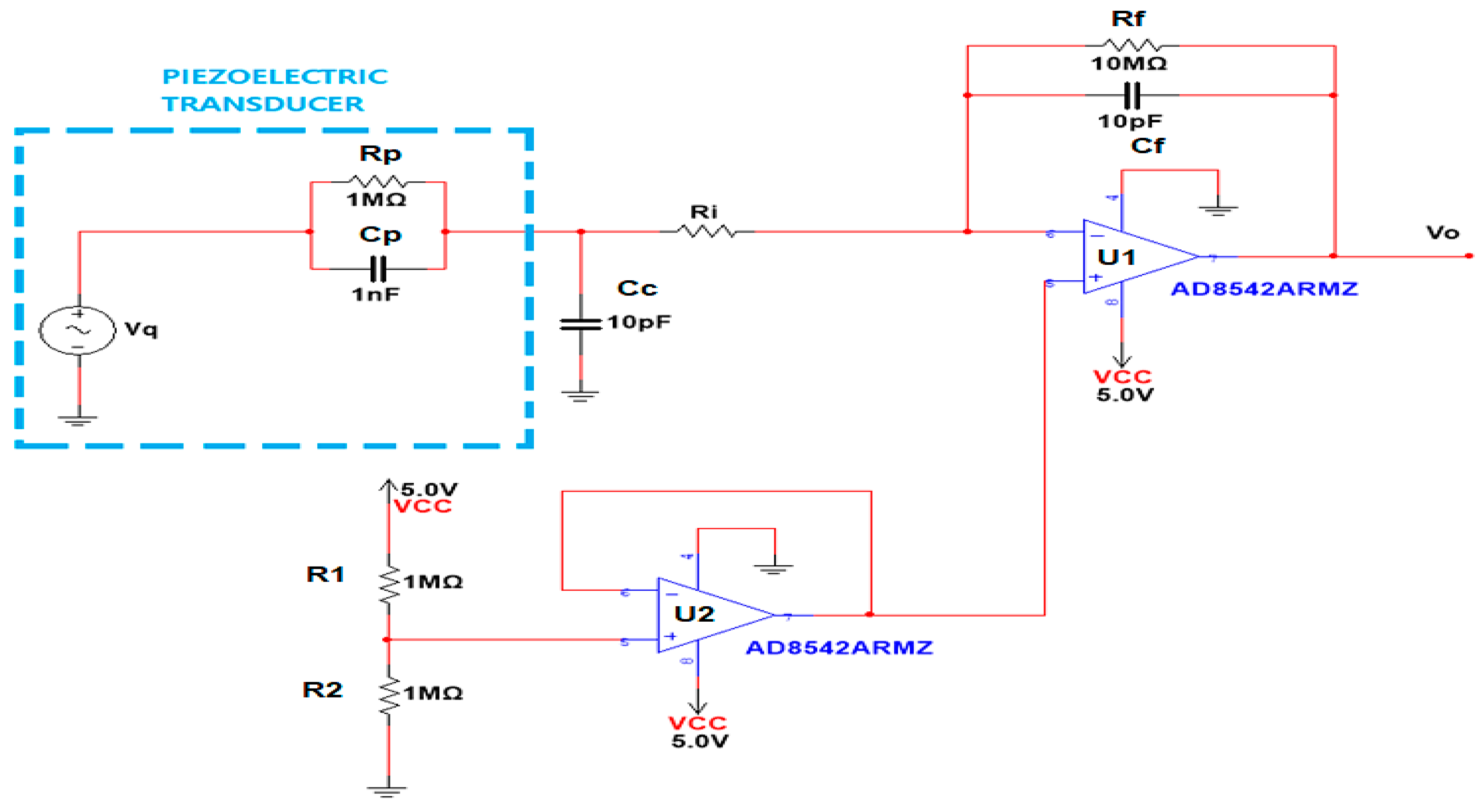
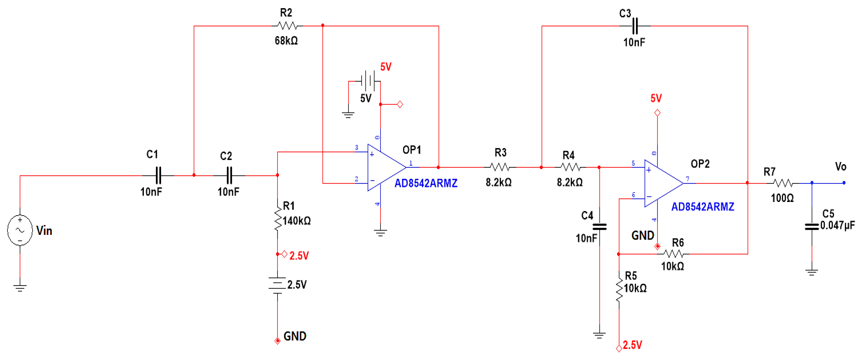
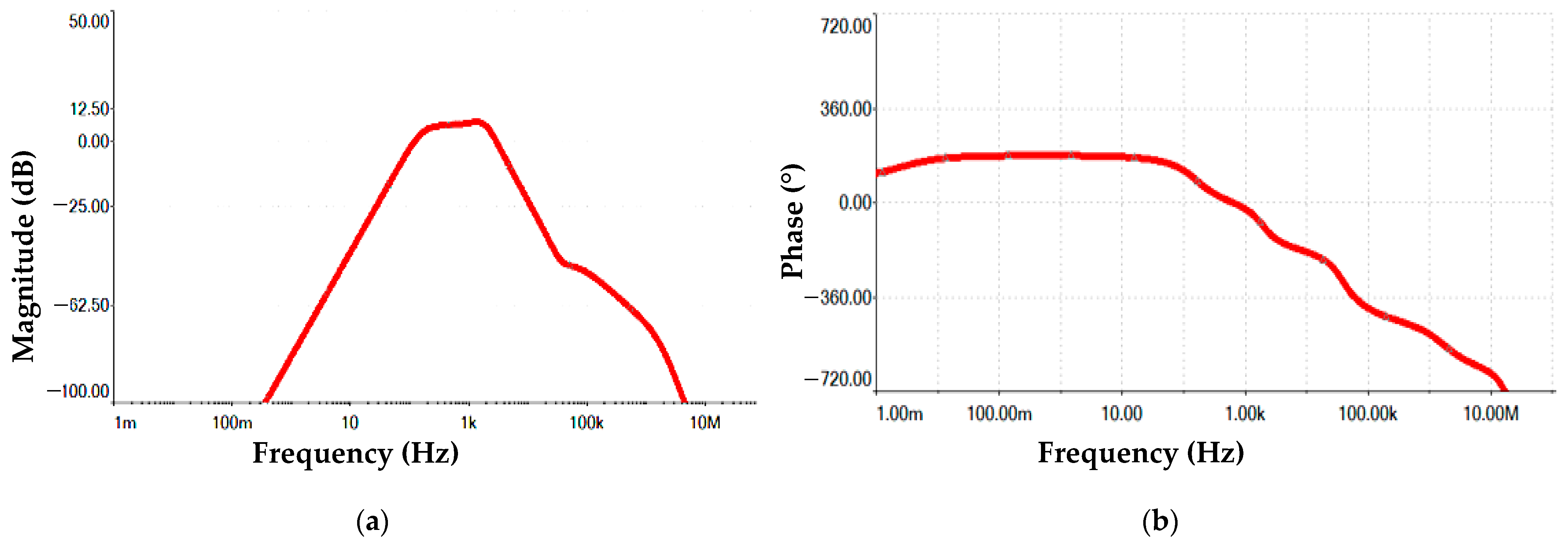
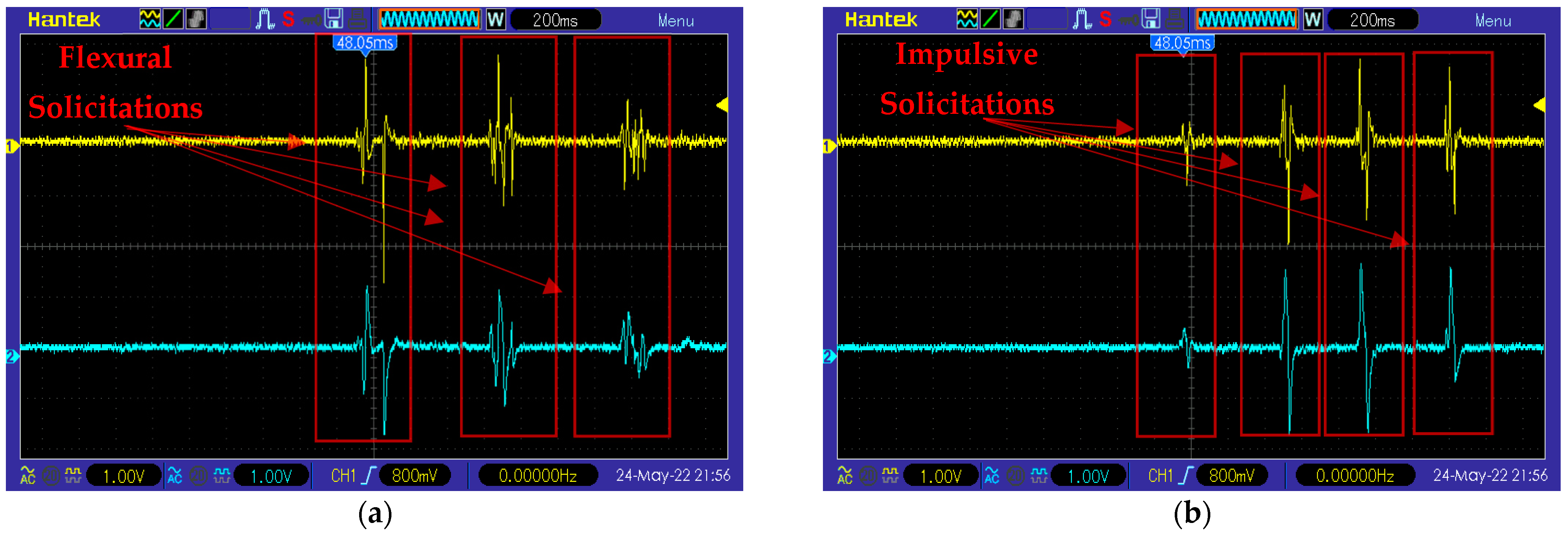
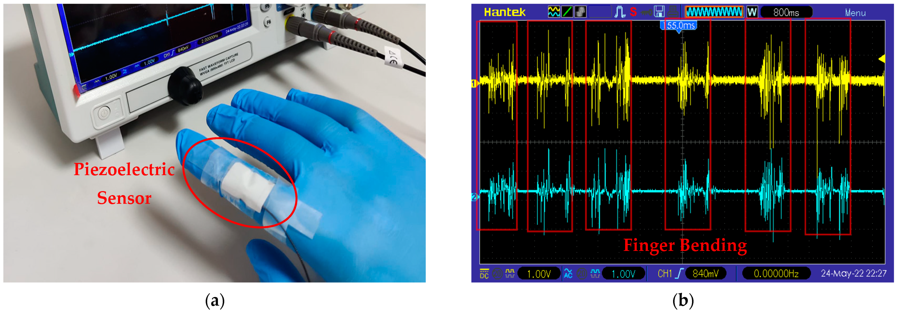
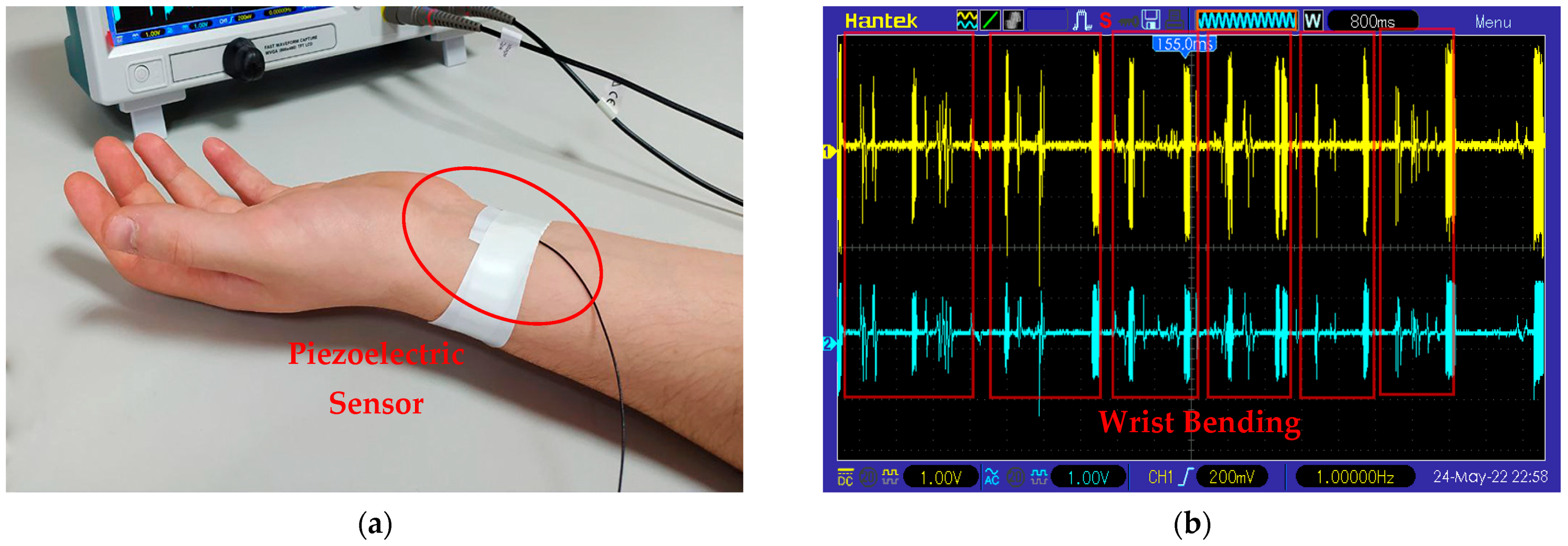
6.1. Development and Testing of the Conditioning Section for the AlN-Based Flexible Sensors
- Preamplifier, which transforms the input signal provided at the sensor’s high-impedance output into a low-impedance signal source.
- Amplifying–filtering block, which filters and amplifies the voltage signal provided in output from the preamplification.
- Analog to digital Converter, which digitalizes the signal provided by the transducer.
- Power supply.
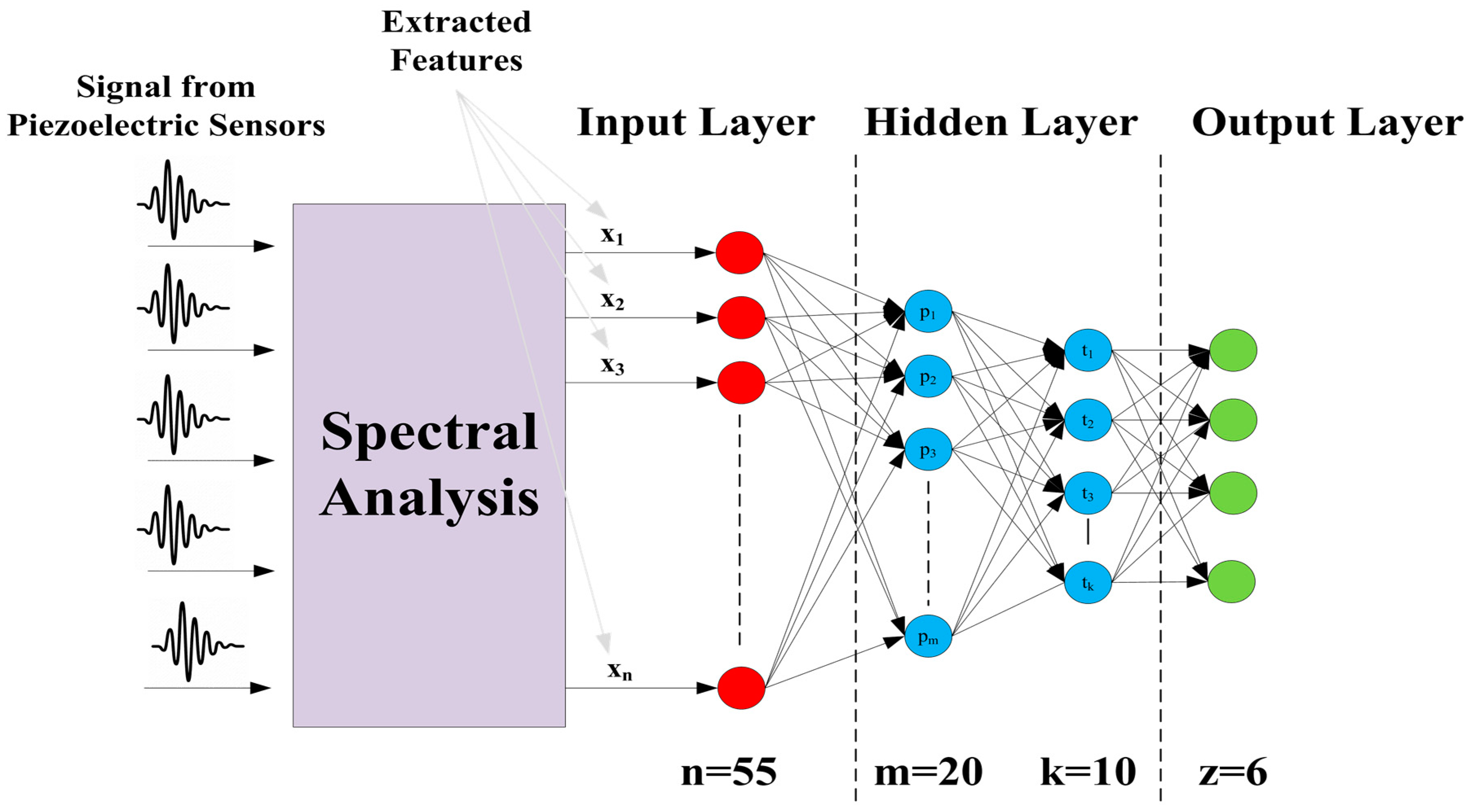
6.2. Architecture of a Hybrid Recognition System Based on the Developed Smart Glove
7. Conclusions
Author Contributions
Funding
Informed Consent Statement
Data Availability Statement
Conflicts of Interest
References
- Wang, H.; Ma, X.; Hao, Y. Electronic Devices for Human-Machine Interfaces. Adv. Mater. Interfaces 2017, 4, 1600709. [Google Scholar] [CrossRef]
- Zhu, M.; He, T.; Lee, C. Technologies toward next Generation Human Machine Interfaces: From Machine Learning Enhanced Tactile Sensing to Neuromorphic Sensory Systems. Appl. Phys. Rev. 2020, 7, 031305. [Google Scholar] [CrossRef]
- Bolton, C.; Machova, V.; Kovacova, M.; Valaskova, K. The Power of Human-Machine Collaboration: Artificial Intelligence, Business, Automation, and the Smart Economy. Econ. Manag. Financ. Mark. 2018, 13, 51–57. [Google Scholar]
- Andrews, C.; Southworth, M.K.; Silva, J.N.A.; Silva, J.R. Extended Reality in Medical Practice. Curr. Treat. Options Cardiovasc. Med. 2019, 21, 1–12. [Google Scholar] [CrossRef] [PubMed]
- Chakraborty, B.K.; Sarma, D.; Bhuyan, M.K.; MacDorman, K.F. Review of Constraints on Vision-Based Gesture Recognition for Human—Computer Interaction. IET Comput. Vis. 2018, 12, 3–15. [Google Scholar] [CrossRef]
- Juraschek, M.; Büth, L.; Posselt, G.; Herrmann, C. Mixed Reality in Learning Factories. Procedia Manuf. 2018, 23, 153–158. [Google Scholar] [CrossRef]
- Bermejo, C.; Hui, P. A Survey on Haptic Technologies for Mobile Augmented Reality. ACM Comput. Surv. 2021, 54, 1–35. [Google Scholar] [CrossRef]
- Yang, T.-H.; Kim, J.R.; Jin, H.; Gil, H.; Koo, J.-H.; Kim, H.J. Recent Advances and Opportunities of Active Materials for Haptic Technologies in Virtual and Augmented Reality. Adv. Funct. Mater. 2021, 31, 2008831. [Google Scholar] [CrossRef]
- Maisto, M.; Pacchierotti, C.; Chinello, F.; Salvietti, G.; De Luca, A.; Prattichizzo, D. Evaluation of Wearable Haptic Systems for the Fingers in Augmented Reality Applications. IEEE Trans. Haptics 2017, 10, 511–522. [Google Scholar] [CrossRef] [Green Version]
- Richter, J.; Thomas, B.H.; Sugimoto, M.; Inami, M. Remote Active Tangible Interactions. In Proceedings of the 1st International Conference on Tangible and Embedded Interaction, Louisiana, LA, USA, 15–17 February 2007; ACM: New York, NY, USA, 2007; pp. 39–42. [Google Scholar]
- Leithinger, D.; Follmer, S.; Olwal, A.; Ishii, H. Physical Telepresence: Shape Capture and Display for Embodied, Computer-Mediated Remote Collaboration. In Proceedings of the 27th Annual ACM Symposium on User Interface Software and Technology, Hawaii, HI, USA, 5–8 October 2014; ACM: New York, NY, USA, 2014; pp. 461–470. [Google Scholar]
- Wang, R.; Quek, F. Touch & Talk: Contextualizing Remote Touch for Affective Interaction. In Proceedings of the Fourth International Conference on Tangible, Embedded, and Embodied Interaction, Massachusetts, MA, USA, 24–27 January 2010; ACM: New York, NY, USA, 2014; pp. 13–20. [Google Scholar]
- Wee, C.; Yap, K.M.; Lim, W.N. Haptic Interfaces for Virtual Reality: Challenges and Research Directions. IEEE Access 2021, 9, 112145–112162. [Google Scholar] [CrossRef]
- Biggs, S.J.; Srinivasan, M.A. Haptic Interfaces. In Handbook of Virtual Environments; CRC Press: Florida, FL, USA, 2002; ISBN 978-0-429-16393-7. [Google Scholar]
- Nitzsche, N.; Hanebeck, U.D.; Schmidt, G. Design Issues of Mobile Haptic Interfaces. J. Robot. Syst. 2003, 20, 549–556. [Google Scholar] [CrossRef]
- Våpenstad, C.; Hofstad, E.F.; Langø, T.; Mårvik, R.; Chmarra, M.K. Perceiving Haptic Feedback in Virtual Reality Simulators. Surg. Endosc. 2013, 27, 2391–2397. [Google Scholar] [CrossRef]
- Sapkaroski, D.; Baird, M.; McInerney, J.; Dimmock, M.R. The Implementation of a Haptic Feedback Virtual Reality Simulation Clinic with Dynamic Patient Interaction and Communication for Medical Imaging Students. J. Med. Radiat. Sci. 2018, 65, 218–225. [Google Scholar] [CrossRef] [PubMed] [Green Version]
- Tannous, M.; Miraglia, M.; Inglese, F.; Giorgini, L.; Ricciardi, F.; Pelliccia, R.; Milazzo, M.; Stefanini, C. Haptic-Based Touch Detection for Collaborative Robots in Welding Applications. Robot. Comput.-Integr. Manuf. 2020, 64, 101952. [Google Scholar] [CrossRef]
- Hamza-Lup, F.G.; Bergeron, K.; Newton, D. Haptic Systems in User Interfaces: State of the Art Survey. In Proceedings of the 2019 ACM Southeast Conference, Georgia, GA, USA, 18–20 April 2019; ACM: New York, NY, USA, 2019; pp. 141–148. [Google Scholar]
- Natta, L.; Guido, F.; Algieri, L.; Mastronardi, V.M.; Rizzi, F.; Scarpa, E.; Qualtieri, A.; Todaro, M.T.; Sallustio, V.; De Vittorio, M. Conformable AlN Piezoelectric Sensors as a Non-Invasive Approach for Swallowing Disorder Assessment. ACS Sens. 2021, 6, 1761–1769. [Google Scholar] [CrossRef] [PubMed]
- Guido, F.; Qualtieri, A.; Algieri, L.; Lemma, E.D.; De Vittorio, M.; Todaro, M.T. AlN-Based Flexible Piezoelectric Skin for Energy Harvesting from Human Motion. Microelectron. Eng. 2016, 159, 174–178. [Google Scholar] [CrossRef]
- Mariello, M.; Fachechi, L.; Guido, F.; Vittorio, M. Conformal, Ultra-Thin Skin-Contact-Actuated Hybrid Piezo/Triboelectric Wearable Sensor Based on AlN and Parylene-Encapsulated Elastomeric Blend. Adv. Funct. Mater. 2021, 31, 2101047. [Google Scholar] [CrossRef]
- Siraj, M.; Sethi, A.; Kumar, A.; Dahiya, P. Haptic Feedback System for Differently Abled Using Their Inputs. In Proceedings of the 2021 9th International Conference on Reliability, Infocom Technologies and Optimization (Trends and Future Directions) (ICRITO), Noida, India, 3–4 September 2021; IEEE: New Jersey, NJ, USA, 2021; pp. 1–4. [Google Scholar]
- Huang, Y.; Yao, K.; Li, J.; Li, D.; Jia, H.; Liu, Y.; Yiu, C.K.; Park, W.; Yu, X. Recent Advances in Multi-Mode Haptic Feedback Technologies towards Wearable Interfaces. Mater. Today Phys. 2022, 22, 100602. [Google Scholar] [CrossRef]
- Chu, R.; Zhang, Y.; Zhang, H.; Xu, W.; Ryu, J.-H.; Wang, D. Co-Actuation: A Method for Achieving High Stiffness and Low Inertia for Haptic Devices. IEEE Trans. Haptics 2020, 13, 312–324. [Google Scholar] [CrossRef]
- Lv, X.; Chen, L.; Dai, C.; Lang, Y.; Tang, R.; He, J. Multimodal Fusion Transcutaneous Electrical System for Haptic Feedback. In Proceedings of the 2019 IEEE International Conference on Advanced Robotics and its Social Impacts (ARSO), Beijing, China, 31 October–2 November 2019; IEEE: New Jersey, NJ, USA, 2019; pp. 102–105. [Google Scholar]
- Crago, P.E.; Nakai, R.J.; Chizeck, H.J. Feedback Regulation of Hand Grasp Opening and Contact Force during Stimulation of Paralyzed Muscle. IEEE Trans. Biomed. Eng. 1991, 38, 17–28. [Google Scholar] [CrossRef]
- Acome, E.; Mitchell, S.K.; Morrissey, T.G.; Emmett, M.B.; Benjamin, C.; King, M.; Radakovitz, M.; Keplinger, C. Hydraulically Amplified Self-Healing Electrostatic Actuators with Muscle-like Performance. Science 2018, 359, 61–65. [Google Scholar] [CrossRef] [PubMed]
- Suo, Z. Theory of Dielectric Elastomers. Acta Mech. Solida Sin. 2010, 23, 549–578. [Google Scholar] [CrossRef]
- Cacucciolo, V.; Shintake, J.; Kuwajima, Y.; Maeda, S.; Floreano, D.; Shea, H. Stretchable Pumps for Soft Machines. Nature 2019, 572, 516–519. [Google Scholar] [CrossRef]
- Leroy, E.; Hinchet, R.; Shea, H. Multimode Hydraulically Amplified Electrostatic Actuators for Wearable Haptics. Adv. Mater. 2020, 9, 2002564. [Google Scholar] [CrossRef] [PubMed]
- Mazursky, A.; Koo, J.-H.; Yang, T.-H. Design, Modeling, and Evaluation of a Slim Haptic Actuator Based on Electrorheological Fluid. J. Intell. Mater. Syst. Struct. 2019, 30, 2521–2533. [Google Scholar] [CrossRef]
- Talhan, A.; Jeon, S. Pneumatic Actuation in Haptic-Enabled Medical Simulators: A Review. IEEE Access 2018, 6, 3184–3200. [Google Scholar] [CrossRef]
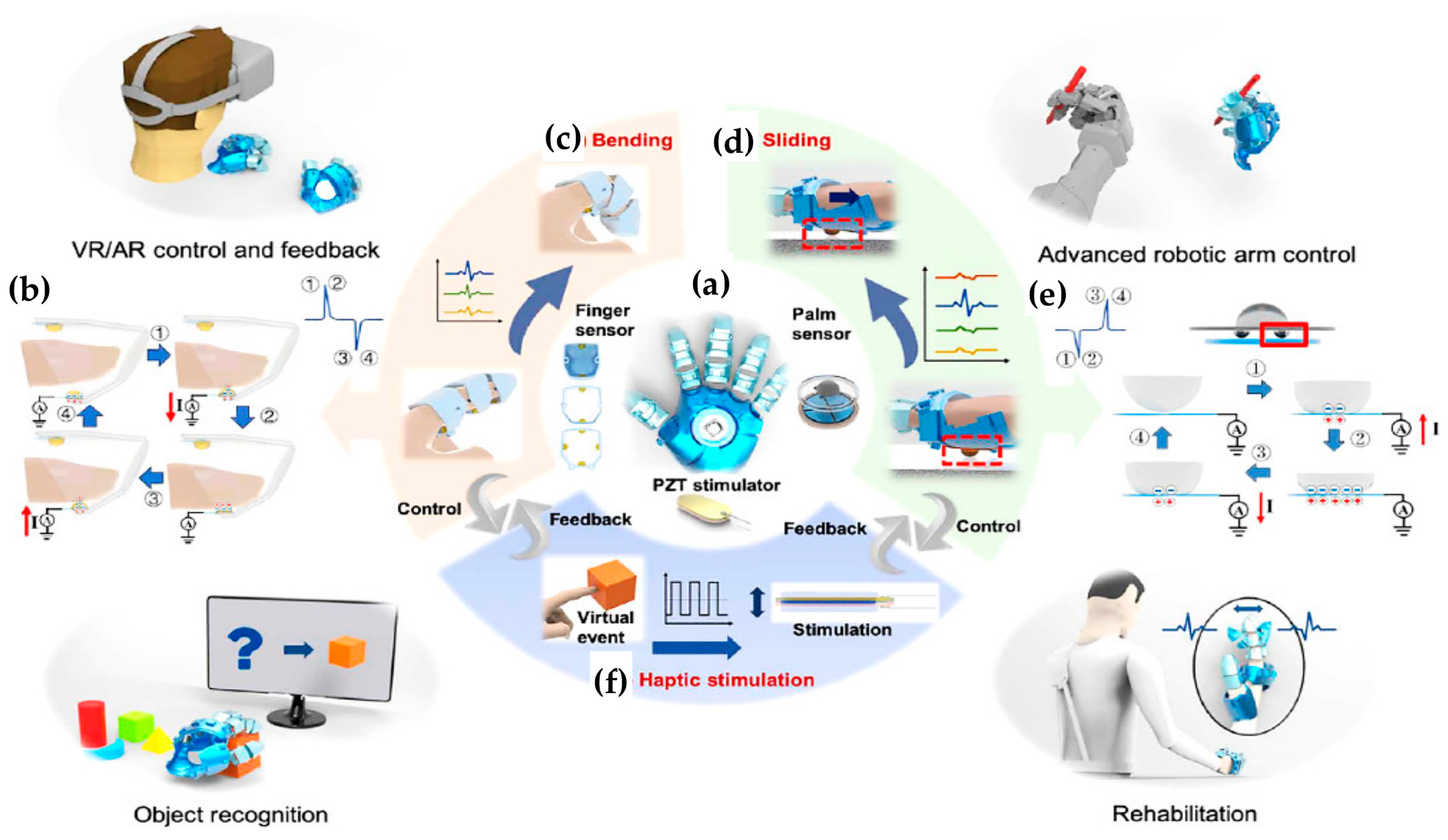
- Zhu, M.; Sun, Z.; Zhang, Z.; Shi, Q.; He, T.; Liu, H.; Chen, T.; Lee, C. Haptic-Feedback Smart Glove as a Creative Human-Machine Interface (HMI) for Virtual/Augmented Reality Applications. Sci. Adv. 2020, 6, eaaz8693. [Google Scholar] [CrossRef]
- Kim, S.; Kim, T.; Kim, C.S.; Choi, H.; Kim, Y.J.; Lee, G.S.; Oh, O.; Cho, B.J. Two-Dimensional Thermal Haptic Module Based on a Flexible Thermoelectric Device. Soft Robot. 2020, 7, 736–742. [Google Scholar] [CrossRef]
- Cai, S.; Ke, P.; Narumi, T.; Zhu, K. ThermAirGlove: A Pneumatic Glove for Thermal Perception and Material Identification in Virtual Reality. In Proceedings of the 2020 IEEE Conference on Virtual Reality and 3D User Interfaces (VR), Atlanta, GA, USA, 22–26 March 2020; IEEE: New Jersey, NJ, USA, 2020; pp. 248–257. [Google Scholar]
- Pyun, K.R.; Rogers, J.A.; Ko, S.H. Materials and Devices for Immersive Virtual Reality. Nat. Rev. Mater. 2022, 7, 841–843. [Google Scholar] [CrossRef]
- Rezania, A.; Rosendahl, L.A. A Comparison of Micro-Structured Flat-Plate and Cross-Cut Heat Sinks for Thermoelectric Generation Application. Energy Convers. Manag. 2015, 101, 730–737. [Google Scholar] [CrossRef]
- Moya, X.; Kar-Narayan, S.; Mathur, N.D. Caloric Materials near Ferroic Phase Transitions. Nat. Mater. 2014, 13, 439–450. [Google Scholar] [CrossRef] [PubMed]
- Zhang, G.; Zhang, X.; Huang, H.; Wang, J.; Li, Q.; Chen, L.-Q.; Wang, Q. Toward Wearable Cooling Devices: Highly Flexible Electrocaloric Ba 0.67 Sr 0.33 TiO 3 Nanowire Arrays. Adv. Mater. 2016, 28, 4811–4816. [Google Scholar] [CrossRef] [PubMed]
- Wang, D.; Chen, X.; Yuan, G.; Jia, Y.; Wang, Y.; Mumtaz, A.; Wang, Y.; Liu, J.-M. Toward Artificial Intelligent Self-Cooling Electronic Skins: Large Electrocaloric Effect in All-Inorganic Flexible Thin Films at Room Temperature. J. Mater. 2019, 5, 66–72. [Google Scholar] [CrossRef]
- Yang, C.; Han, Y.; Feng, C.; Lin, X.; Huang, S.; Cheng, X.; Cheng, Z. Toward Multifunctional Electronics: Flexible NBT-Based Film with a Large Electrocaloric Effect and High Energy Storage Property. ACS Appl. Mater. Interfaces 2020, 12, 6082–6089. [Google Scholar] [CrossRef]
- Yang, Y.; Zhou, Y.; Zeng, J.; He, K.; Liu, H. Electrotactile Stimulation Waveform Modulation Based on A Customized Portable Stimulator: A Pilot Study. In Proceedings of the 2019 IEEE International Conference on Systems, Man and Cybernetics (SMC), Bari, Italy, 6–9 October 2019; IEEE: New Jersey, NJ, USA, 2019; pp. 1838–1843. [Google Scholar]
- Kaczmarek, K.A.; Webster, J.G.; Bach-y-Rita, P.; Tompkins, W.J. Electrotactile and Vibrotactile Displays for Sensory Substitution Systems. IEEE Trans. Biomed. Eng. 1991, 38, 1–16. [Google Scholar] [CrossRef] [PubMed] [Green Version]
- Akhtar, A.; Sombeck, J.; Boyce, B.; Bretl, T. Controlling Sensation Intensity for Electrotactile Stimulation in Human-Machine Interfaces. Sci. Robot. 2018, 3, eaap9770. [Google Scholar] [CrossRef] [Green Version]
- Carpenter, C.W.; Malinao, M.G.; Rafeedi, T.A.; Rodriquez, D.; Tan, S.T.M.; Root, N.B.; Skelil, K.; Ramírez, J.; Polat, B.; Root, S.E.; et al. Electropneumotactile Stimulation: Multimodal Haptic Actuators Enabled by a Stretchable Conductive Polymer on Inflatable Pockets. Adv. Mater. Technol. 2020, 5, 1901119. [Google Scholar] [CrossRef]
- Frohner, J.; Salvietti, G.; Beckerle, P.; Prattichizzo, D. Can Wearable Haptic Devices Foster the Embodiment of Virtual Limbs? IEEE Trans. Haptics 2019, 12, 339–349. [Google Scholar] [CrossRef]
- Biocca, F. The Cyborg’s Dilemma: Progressive Embodiment in Virtual Environments. J. Comput.-Mediat. Commun. 1997, 3, JCMC324. [Google Scholar] [CrossRef]
- Romano, J.M.; Hsiao, K.; Niemeyer, G.; Chitta, S.; Kuchenbecker, K.J. Human-Inspired Robotic Grasp Control With Tactile Sensing. IEEE Trans. Robot. 2011, 27, 1067–1079. [Google Scholar] [CrossRef]
- Silvera-Tawil, D.; Rye, D.; Velonaki, M. Artificial Skin and Tactile Sensing for Socially Interactive Robots: A Review. Robot. Auton. Syst. 2015, 63, 230–243. [Google Scholar] [CrossRef]
- Girão, P.S.; Ramos, P.M.P.; Postolache, O.; Pereira, J.M.D. Tactile Sensors for Robotic Applications. Measurement 2013, 46, 1257–1271. [Google Scholar] [CrossRef]
- Witteveen, H.J.; Rietman, H.S.; Veltink, P.H. Vibrotactile Grasping Force and Hand Aperture Feedback for Myoelectric Forearm Prosthesis Users. Prosthet. Orthot. Int. 2015, 39, 204–212. [Google Scholar] [CrossRef] [PubMed]
- Dietrich, C.; Walter-Walsh, K.; Preißler, S.; Hofmann, G.O.; Witte, O.W.; Miltner, W.H.; Weiss, T. Sensory Feedback Prosthesis Reduces Phantom Limb Pain: Proof of a Principle. Neurosci. Lett. 2012, 507, 97–100. [Google Scholar] [CrossRef] [PubMed]
- Wijk, U.; Carlsson, I. Forearm Amputees’ Views of Prosthesis Use and Sensory Feedback. J. Hand Ther. 2015, 28, 269–278. [Google Scholar] [CrossRef]
- Shehata, A.W.; Rehani, M.; Jassat, Z.E.; Hebert, J.S. Mechanotactile Sensory Feedback Improves Embodiment of a Prosthetic Hand During Active Use. Front. Neurosci. 2020, 14, 263. [Google Scholar] [CrossRef]
- Yunus, R.; Ali, S.; Ayaz, Y.; Khan, M.; Kanwal, S.; Akhlaque, U.; Nawaz, R. Development and Testing of a Wearable Vibrotactile Haptic Feedback System for Proprioceptive Rehabilitation. IEEE Access 2020, 8, 35172–35184. [Google Scholar] [CrossRef]
- Parmar, S.; Khodasevych, I.; Troynikov, O. Evaluation of Flexible Force Sensors for Pressure Monitoring in Treatment of Chronic Venous Disorders. Sensors 2017, 17, 1923. [Google Scholar] [CrossRef]
- Hotson, G.; McMullen, D.P.; Fifer, M.S.; Johannes, M.S.; Katyal, K.D.; Para, M.P.; Armiger, R.; Anderson, W.S.; Thakor, N.V.; Wester, B.A. Individual Finger Control of a Modular Prosthetic Limb Using High-Density Electrocorticography in a Human Subject. J. Neural Eng. 2016, 13, 026017. [Google Scholar] [CrossRef] [Green Version]
- Precision Microdrives Inc. The Limits of Vibration Frequency for Miniature Vibration Motors. Available online: https://www.precisionmicrodrives.com/the-limits-of-vibration-frequency-for-miniature-vibration-motors (accessed on 19 May 2022).
- Zhao, G.; Yang, J.; Chen, J.; Zhu, G.; Jiang, Z.; Liu, X.; Niu, G.; Wang, Z.L.; Zhang, B. Keystroke Dynamics Identification Based on Triboelectric Nanogenerator for Intelligent Keyboard Using Deep Learning Method. Adv. Mater. Technol. 2019, 4, 1800167. [Google Scholar] [CrossRef] [Green Version]
- Zhang, W.; Wang, P.; Sun, K.; Wang, C.; Diao, D. Intelligently Detecting and Identifying Liquids Leakage Combining Triboelectric Nanogenerator Based Self-Powered Sensor with Machine Learning. Nano Energy 2019, 56, 277–285. [Google Scholar] [CrossRef]
- Wu, C.; Ding, W.; Liu, R.; Wang, J.; Wang, A.C.; Wang, J.; Li, S.; Zi, Y.; Wang, Z.L. Keystroke Dynamics Enabled Authentication and Identification Using Triboelectric Nanogenerator Array. Mater. Today 2018, 21, 216–222. [Google Scholar] [CrossRef]
- He, Q.; Wu, Y.; Feng, Z.; Sun, C.; Fan, W.; Zhou, Z.; Meng, K.; Fan, E.; Yang, J. Triboelectric Vibration Sensor for a Human-Machine Interface Built on Ubiquitous Surfaces. Nano Energy 2019, 59, 689–696. [Google Scholar] [CrossRef]
- Kunzler, U.; Runde, C. Kinesthetic Haptics Integration into Large-Scale Virtual Environments. In Proceedings of the First Joint Eurohaptics Conference and Symposium on Haptic Interfaces for Virtual Environment and Teleoperator Systems. World Haptics Conference, Pisa, Italy, 18–20 March 2005; IEEE: New Jersey, NJ, USA, 2005; pp. 551–556. [Google Scholar]
- Loomis, J.M.; Marston, J.R.; Golledge, R.G.; Klatzky, R.L. Personal Guidance System for People with Visual Impairment: A Comparison of Spatial Displays for Route Guidance. J. Vis. Impair. Blind. 2005, 99, 219–232. [Google Scholar] [CrossRef]
- Bolopion, A.; Xie, H.; Halayo, D.S.; Regnier, S. Haptic Teleoperation for 3-D Microassembly of Spherical Objects. IEEE/ASME Trans. Mechatron. 2012, 17, 116–127. [Google Scholar] [CrossRef]
- Guinan, A.L.; Montandon, M.N.; Doxon, A.J.; Provancher, W.R. An Ungrounded Tactile Feedback Device to Portray Force and Torque-like Interactions in Virtual Environments. In Proceedings of the 2014 IEEE Virtual Reality (VR), Minneapolis, MN, USA, 29 March–2 April 2014; IEEE: New Jersey, NJ, USA, 2014; pp. 171–172. [Google Scholar]
- Tsetserukou, D.; Hosokawa, S.; Terashima, K. LinkTouch: A Wearable Haptic Device with Five-Bar Linkage Mechanism for Presentation of Two-DOF Force Feedback at the Fingerpad. In Proceedings of the 2014 IEEE Haptics Symposium (HAPTICS), Texas, TX, USA, 23–26 February 2014; IEEE: New Jersey, NJ, USA, 2014; pp. 307–312. [Google Scholar]
- Sauvet, B.; Laliberte, T.; Gosselin, C. Design, Analysis and Experimental Validation of an Ungrounded Haptic Interface Using a Piezoelectric Actuator. Mechatronics 2017, 45, 100–109. [Google Scholar] [CrossRef]
- Amemiya, T.; Gomi, H. Distinct Pseudo-Attraction Force Sensation by a Thumb-Sized Vibrator That Oscillates Asymmetrically. In Proceedings of the International Conference on Human Haptic Sensing and Touch Enabled Computer Applications, Versailles, France, 24–26 June 2014; Springer: Berlin/Heidelberg, Germany, 2014; pp. 88–95. [Google Scholar]
- Amemiya, T.; Ando, H.; Maeda, T. Lead-Me Interface for a Pulling Sensation from Hand-Held Devices. ACM Trans. Appl. Percept. (TAP) 2008, 5, 1–17. [Google Scholar] [CrossRef]
- Amemiya, T.; Maeda, T. Directional Force Sensation by Asymmetric Oscillation from a Double-Layer Slider-Crank Mechanism. J. Comput. Inf. Sci. Eng. 2009, 9, 1–8. [Google Scholar] [CrossRef]
- Amemiya, T.; Sugiyama, H. Haptic Handheld Wayfinder with Pseudo-Attraction Force for Pedestrians with Visual Impairments. In Proceedings of the 11th International ACM SIGACCESS Conference on Computers and Accessibility, Pennsylvania, PA, USA, 25–28 October 2009; Association for Computing Machinery: New York, NY, USA, 2009; pp. 107–114. [Google Scholar]
- Ito, M.; Wakuda, D.; Inoue, S.; Makino, Y.; Shinoda, H. High Spatial Resolution Midair Tactile Display Using 70 KHz Ultrasound. In Proceedings of the International Conference on Human Haptic Sensing and Touch Enabled Computer Applications, London, UK, 4–7 July 2016; Springer: Berlin/Heidelberg, Germany, 2016; pp. 57–67. [Google Scholar]
- Carter, T.; Seah, S.A.; Long, B.; Drinkwater, B.; Subramanian, S. UltraHaptics: Multi-Point Mid-Air Haptic Feedback for Touch Surfaces. In Proceedings of the 26th Annual ACM Symposium on User Interface Software and Technology, St. Andrews Scotland, UK, 8–11 October 2013; ACM: New York, NY, USA, 2013; pp. 505–514. [Google Scholar]
- Van Neer, P.; Volker, A.W.F.; Berkhoff, A.P.; Akkerman, H.B.; Schrama, T.; Van Breemen, A.; Gelinck, G.H. Feasiblity of Using Printed Polymer Transducers for Mid-Air Haptic Feedback. In Proceedings of the 2018 IEEE International Ultrasonics Symposium (IUS), Kobe, Japan, 22–25 October 2018; IEEE: New Jersey, NJ, USA, 2018; pp. 1–4. [Google Scholar]
- Shi, X.; Shi, D.; Li, W.L.; Wang, Q. A Unified Method for Free Vibration Analysis of Circular, Annular and Sector Plates with Arbitrary Boundary Conditions. J. Vib. Control. 2016, 22, 442–456. [Google Scholar] [CrossRef]
- Vallbo, A.B.; Johansson, R.S. Properties of Cutaneous Mechanoreceptors in the Human Hand-Related to Touch Sensation. Hum. Neurobiol. 1984, 9, 3–14. [Google Scholar]
- Johnson, K.O. The Roles and Functions of Cutaneous Mechanoreceptors. Curr. Opin. Neurobiol. 2001, 11, 455–461. [Google Scholar] [CrossRef] [PubMed]
- Ertan, S.; Lee, C.; Willets, A.; Tan, H.; Pentland, A. A Wearable Haptic Navigation Guidance System. In Digest of Papers, Proceedings of the 2nd International Symposium on Wearable Computers, Pennsylvania, PA, USA, 19–20 October 1998; IEEE: New Jersey, NJ, USA, 1998; pp. 164–165. [Google Scholar]
- Flores, G.; Kurniawan, S.; Manduchi, R.; Martinson, E.; Morales, L.M.; Sisbot, E.A. Vibrotactile Guidance for Wayfinding of Blind Walkers. IEEE Trans. Haptics 2015, 8, 306–317. [Google Scholar] [CrossRef] [PubMed]
- Aggravi, M.; Salvietti, G.; Prattichizzo, D. Haptic Assistive Bracelets for Blind Skier Guidance. In Proceedings of the 7th Augmented Human International Conference 2016, Geneva, Switzerland, 25–27 February 2016; Association for Computing Machinery: New York, NY, USA, 2016; pp. 1–4. [Google Scholar]
- Baik, S.; Han, I.; Park, J.-M.; Park, J. Multi-Fingertip Vibrotactile Array Interface for 3D Virtual Interaction. In Proceedings of the 2020 IEEE Haptics Symposium (HAPTICS), Virginia, VA, USA, 26–29 March 2020; IEEE: New Jersey, NJ, USA, 2020; pp. 898–903. [Google Scholar]
- Kim, J.; Oh, Y.; Park, J. Adaptive Vibrotactile Flow Rendering of 2.5 D Surface Features on Touch Screen with Multiple Fingertip Interfaces. In Proceedings of the 2017 IEEE World Haptics Conference (WHC), Munich, Germany, 6–9 June 2017; IEEE: New Jersey, NJ, USA, 2017; pp. 316–321. [Google Scholar]
- Nunez, O.J.A.; Lubos, P.; Steinicke, F. HapRing: A Wearable Haptic Device for 3D Interaction. In Proceedings of the Mensch & computer, Stuttgart, Germany, 6–9 September 2015; De Gruyter: Berlin, Germany, 2015; pp. 421–424. [Google Scholar]
- Israr, A.; Poupyrev, I. Tactile Brush: Drawing on Skin with a Tactile Grid Display. In Proceedings of the SIGCHI Conference on Human Factors in Computing Systems, Vancouver, BC, Canada, 7–12 May 2011; Association for Computing Machinery: New York, NY, USA, 2011; pp. 2019–2028. [Google Scholar]
- Makous, J.C.; Friedman, R.M.; Vierck, C.J. A Critical Band Filter in Touch. J. Neurosci. 1995, 15, 2808–2818. [Google Scholar] [CrossRef] [PubMed]
- Park, J.; Kim, J.; Oh, Y.; Tan, H.Z. Rendering Moving Tactile Stroke on the Palm Using a Sparse 2d Array. In Proceedings of the International Conference on Human Haptic Sensing and Touch Enabled Computer Applications, Hamburg, Germany, 22–25 March 2016; Springer: Berlin/Heidelberg, Germany, 2016; pp. 47–56. [Google Scholar]
- Son, B.; Park, J. Haptic Feedback to the Palm and Fingers for Improved Tactile Perception of Large Objects. In Proceedings of the 31st Annual ACM Symposium on User Interface Software and Technology, Berlin, Germany, 14–17 October 2018; ACM: New York, NY, USA, 2018; pp. 757–763. [Google Scholar]
- You, X.; Wang, C.-X.; Huang, J.; Gao, X.; Zhang, Z.; Wang, M.; Huang, Y.; Zhang, C.; Jiang, Y.; Wang, J. Towards 6G Wireless Communication Networks: Vision, Enabling Technologies, and New Paradigm Shifts. Sci. China Inf. Sci. 2021, 64, 1–74. [Google Scholar] [CrossRef]
- De Fazio, R.; Giannoccaro, N.I.; Carrasco, M.; Velazquez, R.; Visconti, P. Wearable Devices and IoT Applications for Detecting Symptoms, Infected Tracking, and Diffusion Containment of the COVID-19 Pandemic: A Survey. Front. Inf. Technol. Electron. Eng. 2021, 1, 1–29. [Google Scholar] [CrossRef]
- De Fazio, R.; De Vittorio, M.; Visconti, P. A BLE-Connected Piezoresistive and Inertial Chest Band for Remote Monitoring of the Respiratory Activity by an Android Application: Hardware Design and Software Optimization. Future Internet 2022, 14, 183. [Google Scholar] [CrossRef]
- Ozioko, O.; Dahiya, R. Smart Tactile Gloves for Haptic Interaction, Communication, and Rehabilitation. Adv. Intell. Syst. 2022, 4, 2100091. [Google Scholar] [CrossRef]
- Steinbach, E.; Strese, M.; Eid, M.; Liu, X.; Bhardwaj, A.; Liu, Q.; Al-Ja’afreh, M.; Mahmoodi, T.; Hassen, R.; El Saddik, A. Haptic Codecs for the Tactile Internet. Proc. IEEE 2018, 107, 447–470. [Google Scholar] [CrossRef] [Green Version]
- Carrasco, M.; Mery, D.; Concha, A.; Velázquez, R.; De Fazio, R.; Visconti, P. An Efficient Point-Matching Method Based on Multiple Geometrical Hypotheses. Electronics 2021, 10, 246. [Google Scholar] [CrossRef]
- Janiesch, C.; Zschech, P.; Heinrich, K. Machine Learning and Deep Learning. Electron. Mark. 2021, 31, 685–695. [Google Scholar] [CrossRef]
- Dahiya, R.S. Epidermal Electronics—Flexible Electronics for Biomedical Applications. In Handbook of Bioelectronics: Directly Interfacing Electronics and Biological Systems; Iniewski, K., Carrara, S., Eds.; Cambridge University Press: Cambridge, MA, USA, 2015; pp. 245–255. ISBN 978-1-139-62953-9. [Google Scholar]
- Luo, S.; Bimbo, J.; Dahiya, R.; Liu, H. Robotic Tactile Perception of Object Properties: A Review. Mechatronics 2017, 48, 54–67. [Google Scholar] [CrossRef] [Green Version]
- Bouton, C.E.; Shaikhouni, A.; Annetta, N.V.; Bockbrader, M.A.; Friedenberg, D.A.; Nielson, D.M.; Sharma, G.; Sederberg, P.B.; Glenn, B.C.; Mysiw, W.J. Restoring Cortical Control of Functional Movement in a Human with Quadriplegia. Nature 2016, 533, 247–250. [Google Scholar] [CrossRef] [PubMed]
- Dervin, S.; Ganguly, P.; Dahiya, R.S. Disposable Electrochemical Sensor Using Graphene Oxide–Chitosan Modified Carbon-Based Electrodes for the Detection of Tyrosine. IEEE Sens. J. 2021, 21, 26226–26233. [Google Scholar] [CrossRef]
- Nikbakhtnasrabadi, F.; El Matbouly, H.; Ntagios, M.; Dahiya, R. Textile-Based Stretchable Microstrip Antenna with Intrinsic Strain Sensing. ACS Appl. Electron. Mater. 2021, 3, 2233–2246. [Google Scholar] [CrossRef]
- Takei, K.; Gao, W.; Wang, C.; Javey, A. Physical and Chemical Sensing with Electronic Skin. Proc. IEEE 2019, 107, 2155–2167. [Google Scholar] [CrossRef]
- Dahiya, R. E-Skin: From Humanoids to Humans [Point of View]. Proc. IEEE 2019, 107, 247–252. [Google Scholar] [CrossRef] [Green Version]
- Dahiya, R.S.; Metta, G.; Valle, M.; Sandini, G. Tactile Sensing—From Humans to Humanoids. IEEE Trans. Robot. 2009, 26, 1–20. [Google Scholar] [CrossRef]
- Saunders, G.H.; Echt, K.V. An Overview of Dual Sensory Impairment in Older Adults: Perspectives for Rehabilitation. Trends Amplif. 2007, 11, 243–258. [Google Scholar] [CrossRef] [Green Version]
- Hyvärinen, L.; Gimble, L.; Sorri, M. Assessment of Vision and Hearing of Deaf-Blind Persons; Royal Victorian Institute for the Blind: Melbourne, Australia, 1990; ISBN 0-949390-11-9. [Google Scholar]
- Grigson, P.; Lofmark, N.; Giblin, R. Hand-Tapper III: A Prototype Communication Device Using Finger-Spelling. Br. J. Vis. Impair. 1991, 9, 13–15. [Google Scholar] [CrossRef]
- Gollner, U.; Bieling, T.; Joost, G. Mobile Lorm Glove: Introducing a Communication Device for Deaf-Blind People. In Proceedings of the Sixth International Conference on Tangible, Embedded and Embodied Interaction, Kingston, ON, Canada, 19–22 February 2012; ACM: New York, NY, USA, 2012; pp. 127–130. [Google Scholar]
- Caporusso, N. A Wearable Malossi Alphabet Interface for Deafblind People. In Proceedings of the Working Conference on Advanced Visual Interfaces, Naples, Italy, 28–30 May 2008; ACM: New York, NY, USA, 2008; pp. 445–448. [Google Scholar]
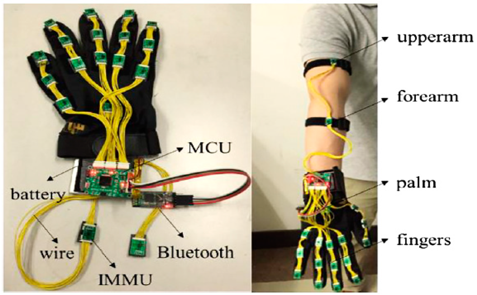
- Fang, B.; Sun, F.; Liu, H.; Liu, C. 3D Human Gesture Capturing and Recognition by the IMMU-Based Data Glove. Neurocomputing 2018, 277, 198–207. [Google Scholar] [CrossRef]
- Chen, S.; Lou, Z.; Chen, D.; Jiang, K.; Shen, G. Polymer-enhanced Highly Stretchable Conductive Fiber Strain Sensor Used for Electronic Data Gloves. Adv. Mater. Technol. 2016, 1, 1600136. [Google Scholar] [CrossRef]
- Bieling, T.; Gollner, U.; Joost, G. What Do You Mean, User Study? Translating Lorm, Norm and User Research. In Proceedings of the DRS International Conference, Bangkok, Thailand, 1–4 July 2012; pp. 102–114. [Google Scholar]
- Rose, T.; Nam, C.S.; Chen, K.B. Immersion of Virtual Reality for Rehabilitation-Review. Appl. Ergon. 2018, 69, 153–161. [Google Scholar] [CrossRef]
- Manjakkal, L.; Pullanchiyodan, A.; Yogeswaran, N.; Hosseini, E.S.; Dahiya, R. A Wearable Supercapacitor Based on Conductive PEDOT: PSS-coated Cloth and a Sweat Electrolyte. Adv. Mater. 2020, 32, 1907254. [Google Scholar] [CrossRef] [PubMed]
- Sorgini, F.; Caliò, R.; Carrozza, M.C.; Oddo, C.M. Haptic-Assistive Technologies for Audition and Vision Sensory Disabilities. Disabil. Rehabil. Assist. Technol. 2018, 13, 394–421. [Google Scholar] [CrossRef] [PubMed]
- Jacobs, I.S. Fine Particles, Thin Films and Exchange Anisotropy. Magnetism 1963, 3, 271–350. [Google Scholar]
- Luca, C.; Andritoi, D.; Corciova, C.; Fuior, R. Intelligent Glove for Rehabilitation of Hand Movement in Stroke Survivor. In Proceedings of the 2020 International Conference and Exposition on Electrical And Power Engineering (EPE), Iasi, Romania, 22–23 October 2020; IEEE: New Jersey, NJ, USA, 2020; pp. 546–549. [Google Scholar]
- Jang, C.H.; Yang, H.S.; Yang, H.E.; Lee, S.Y.; Kwon, J.W.; Yun, B.D.; Choi, J.Y.; Kim, S.N.; Jeong, H.W. A Survey on Activities of Daily Living and Occupations of Upper Extremity Amputees. Ann. Rehabil. Med. 2011, 35, 907–921. [Google Scholar] [CrossRef]
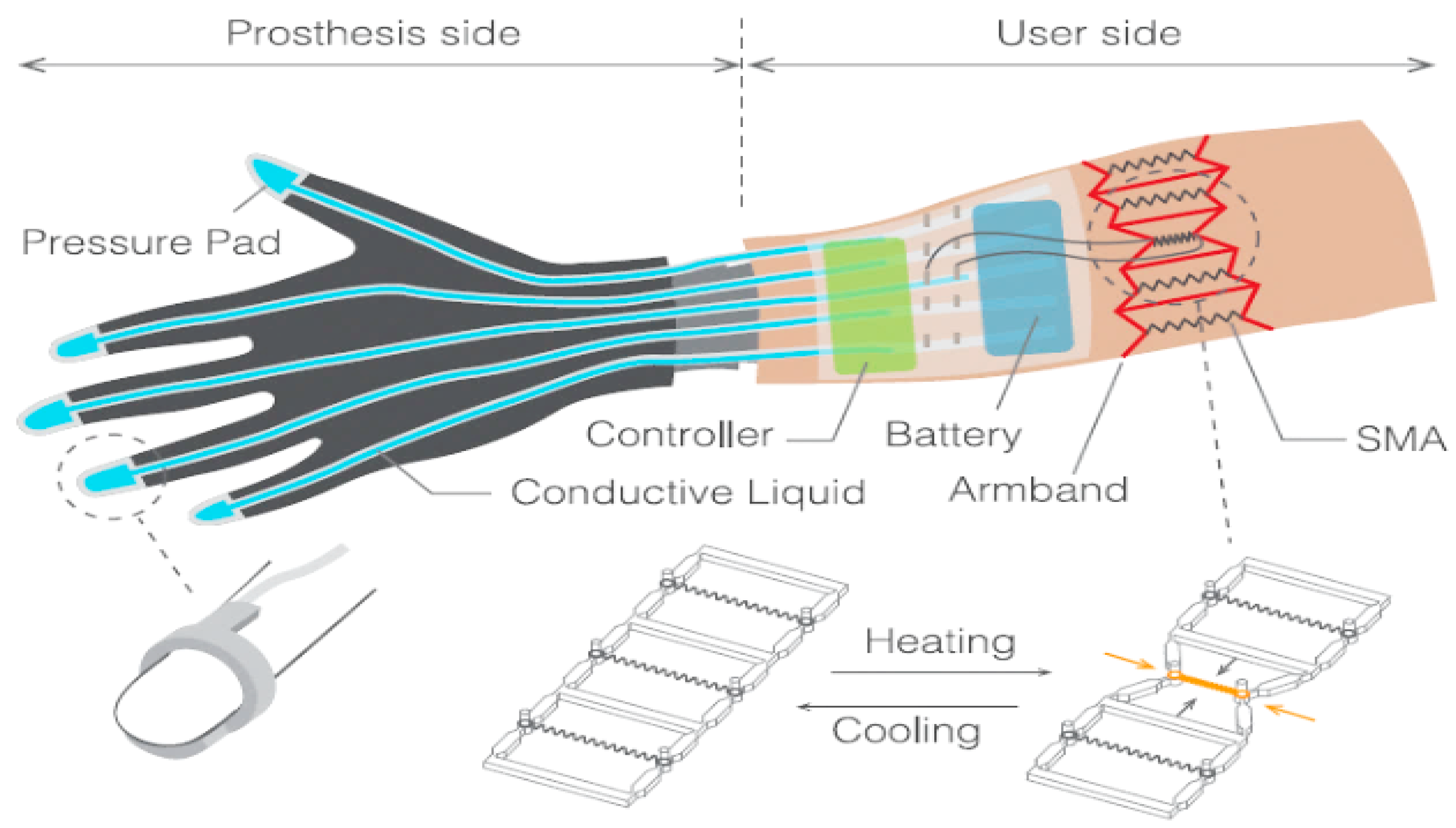
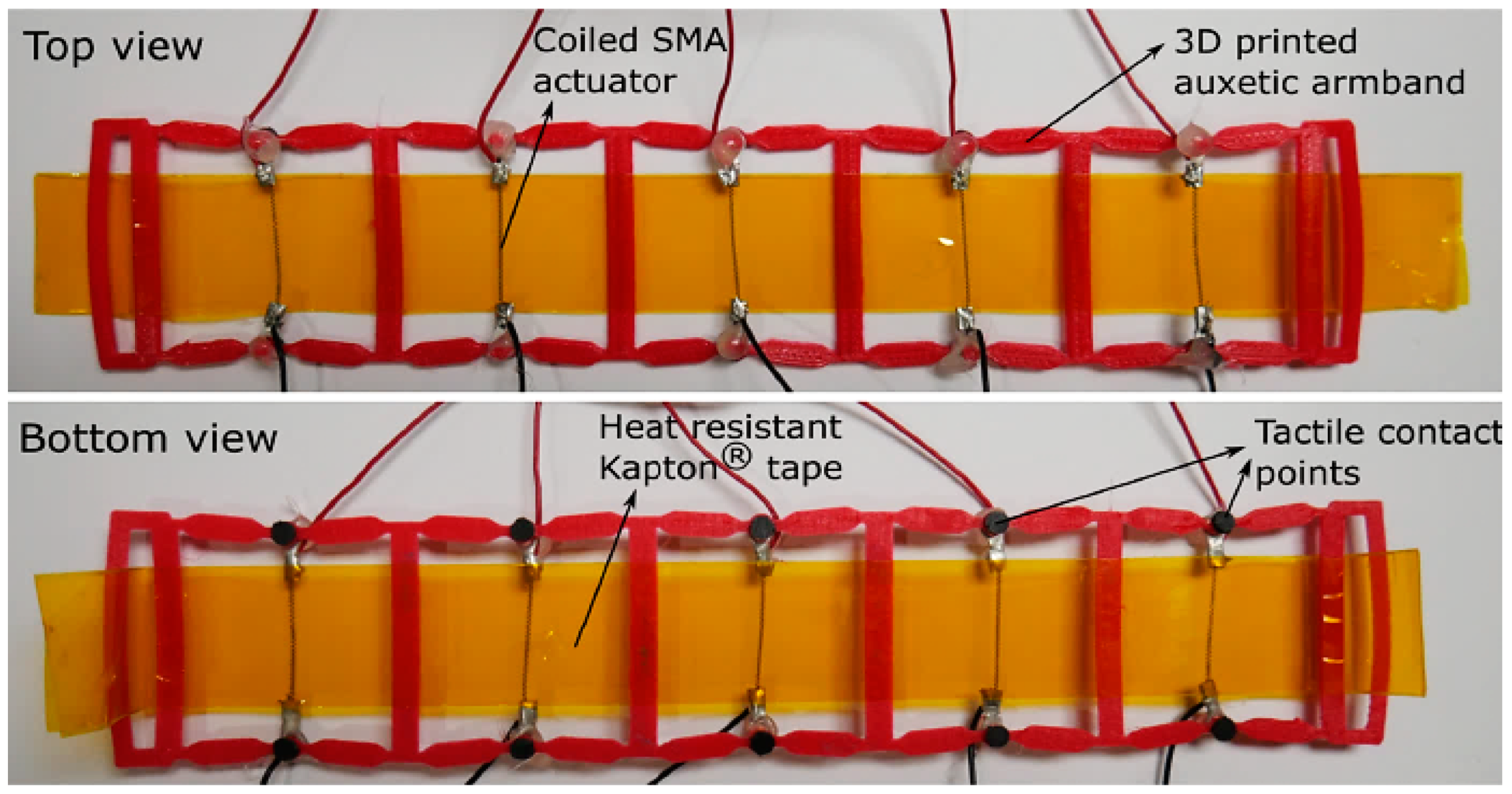
- Simons, M.F.; Digumarti, K.M.; Le, N.H.; Chen, H.-Y.; Carreira, S.C.; Zaghloul, N.S.S.; Diteesawat, R.S.; Garrad, M.; Conn, A.T.; Kent, C.; et al. B:Ionic Glove: A Soft Smart Wearable Sensory Feedback Device for Upper Limb Robotic Prostheses. IEEE Robot. Autom. Lett. 2021, 6, 3311–3316. [Google Scholar] [CrossRef]
- Simons, M.F.; Haynes, A.C.; Gao, Y.; Zhu, Y.; Rossiter, J. In Contact: Pinching, Squeezing and Twisting for Mediated Social Touch. In Proceedings of the Extended Abstracts of the 2020 CHI Conference on Human Factors in Computing Systems, Honolulu, HI, USA, 25–30 April 2020; ACM: New York, NY, USA, 2020; pp. 1–9. [Google Scholar]
- Garrad, M.; Soter, G.; Conn, A.T.; Hauser, H.; Rossiter, J. A Soft Matter Computer for Soft Robots. Sci. Robot. 2019, 4, eaaw6060. [Google Scholar] [CrossRef] [Green Version]
- Bhatia, K.P.; Bain, P.; Bajaj, N.; Elble, R.J.; Hallett, M.; Louis, E.D.; Raethjen, J.; Stamelou, M.; Testa, C.M.; Deuschl, G. Consensus Statement on the Classification of Tremors. from the Task Force on Tremor of the International Parkinson and Movement Disorder Society. Mov. Disord. 2018, 33, 75–87. [Google Scholar] [CrossRef]
- Wanasinghe, A.T.; Awantha, W.V.I.; Kavindya, A.G.P.; Kulasekera, A.L.; Chathuranga, D.S.; Senanayake, B. A Layer Jamming Soft Glove for Hand Tremor Suppression. IEEE Trans. Neural Syst. Rehabil. Eng. 2021, 29, 2684–2694. [Google Scholar] [CrossRef]
- Kavindya, P.; Awantha, W.V.I.; Wanasinghe, A.T.; Kulasekera, A.L.; Chathuranga, D.S.; Senanayake, B. Evaluation of Hand Tremor Frequency among Patients in Sri Lanka Using a Soft Glove. In Proceedings of the 2020 Moratuwa Engineering Research Conference (MERCon), Moratuwa, Sri Lanka, 28–30 July 2020; IEEE: New Jersey, NJ, USA, 2020; pp. 301–306. [Google Scholar]
- Awantha, W.V.I.; Wanasinghe, A.T.; Kavindya, A.G.P.; Kulasekera, A.L.; Chathuranga, D.S. A Novel Soft Glove for Hand Tremor Suppression: Evaluation of Layer Jamming Actuator Placement. In Proceedings of the 2020 3rd IEEE International Conference on Soft Robotics (RoboSoft), Connecticut, CT, USA, 15 May–15 July 2020; IEEE: New Jersey, NJ, USA, 2020; pp. 440–445. [Google Scholar]
- De Fazio, R.; Al-Hinnawi, A.-R.; De Vittorio, M.; Visconti, P. An Energy-Autonomous Smart Shirt Employing Wearable Sensors for Users’ Safety and Protection in Hazardous Workplaces. Appl. Sci. 2022, 12, 2926. [Google Scholar] [CrossRef]
- De Fazio, R.; Cafagna, D.; Marcuccio, G.; Minerba, A.; Visconti, P. A Multi-Source Harvesting System Applied to Sensor-Based Smart Garments for Monitoring Workers’ Bio-Physical Parameters in Harsh Environments. Energies 2020, 13, 2161. [Google Scholar] [CrossRef]
- Edge Impulse. Available online: https://www.edgeimpulse.com/ (accessed on 9 September 2022).
- Starecki, T. Analog Front-End Circuitry in Piezoelectric and Microphone Detection of Photoacoustic Signals. Int. J. Thermophys. 2014, 35, 2124–2139. [Google Scholar] [CrossRef]
- Webster, J.G.; Eren, H. Measurement, Instrumentation, and Sensors Handbook: Two-Volume Set (Electrical Engineering Handbook); CRC Press: Boca Raton, FL, USA, 2014. [Google Scholar]
- Pallas-Areny, R.; Webster, J.G. Sensors and Signal Conditioning; John Wiley & Sons: New Jersey, NJ, USA, 2012; ISBN 1-118-58593-3. [Google Scholar]
- Graeme, J. Photodiode Amplifiers: Op Amp Solutions; McGraw-Hill, Inc.: New York, NY, USA, 1995; ISBN 0-07-024247-X. [Google Scholar]
- Oven, R. Modified Charge Amplifier for Stray Immune Capacitance Measurements. IEEE Trans. Instrum. Meas. 2014, 63, 1748–1752. [Google Scholar] [CrossRef]
- Karki, J. Analysis of the Sallen-Key Architecture; Application Report for Texas Instruments: Texas, TX, USA, 1999; pp. 1–14. [Google Scholar]
- Karki, J. Active Low-Pass Filter Design; Application Report for Texas Instruments: Texas, TX, USA, 2000; pp. 1–22. [Google Scholar]
- Calabrese, B.; Velázquez, R.; Del-Valle-Soto, C.; de Fazio, R.; Giannoccaro, N.I.; Visconti, P. Solar-Powered Deep Learning-Based Recognition System of Daily Used Objects and Human Faces for Assistance of the Visually Impaired. Energies 2020, 13, 6104. [Google Scholar] [CrossRef]
- Sandler, M.; Howard, A.; Zhu, M.; Zhmoginov, A.; Chen, L.-C. MobileNetV2: Inverted Residuals and Linear Bottlenecks. arXiv 2019, arXiv:1801.04381. [Google Scholar] [CrossRef]
- The Centre for Seech Technology Research FeThe Festival Speech Synthesis Systemstival. Available online: https://www.cstr.ed.ac.uk/projects/festival/ (accessed on 12 November 2022).


| Approach | Actuator | Mechanical Feedback | Tactile Feedback | Advantages | Disadvantages |
|---|---|---|---|---|---|
| Force-based haptic Devices | Pneumatic actuators | Yes | Force, shape, and impact | Efficiently stretching force, out-of-plane displacements | Low-speed actuator response, safety issues, complex structure |
| Hydraulic actuators | Yes | Force, shape, and impact | Efficiently stretching force, out-of-plane displacements | Low-speed actuator response, safety issues, complex structure | |
| Piezoelectric actuators | No | Pattern, hardness, and roughness | Compact size and fast response time | Weak output due to low piezoelectric film displacement | |
| Electro-magnetic actuators | No | Pattern, roughness | Lower power consumption, fast responsiveness, high haptic strength | Narrow operating frequency, not-so-small packaging | |
| Thermal-based haptic devices | Joule heater | No | Warming | Simple structure | Lack of cooling microstructure and dissipation structure |
| Thermoelectric actuators | No | Warming, Cooling | Complete cooling and heating manipulation | Complex structure, also for wearable due to necessarily develop a certain material for these kinds of applications | |
| Microfluidic systems | No | Warming, Cooling | Complete cooling and heating manipulation | Complex design | |
| Nerve stimulation haptic devices | Electrotactile stimulation | Yes | Impact, pattern, roughness, and hardness | Compact, wide bandwidth, multi-mode, simple and compact design | Tickling feeling, Unstable contact resistance (due to impedance conflicts), Unstable feelings and unclear bio-mechanism |
| Device | Application | N. of Actuators/Sensors | Actuators or Sensors Technology | Feedback Typology | Future Applications |
|---|---|---|---|---|---|
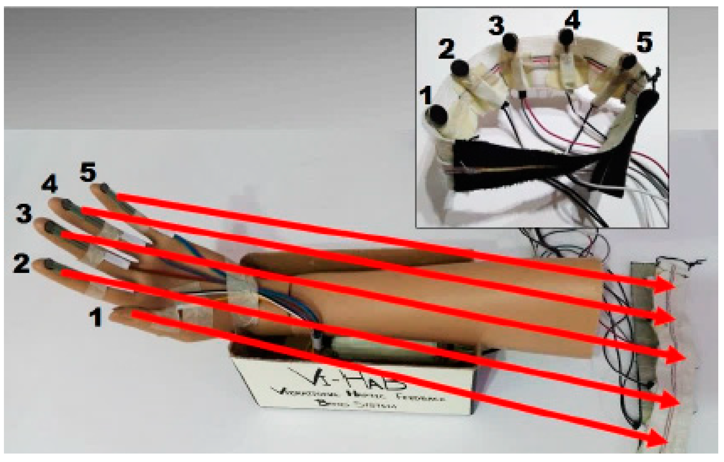
| Vi-Hab band [56] | Rehabilitation systems (biomedical) | (5) Vibrational coin motors | Vibrotactile | Kinesthetic Feedback (independent and simultaneous) | Force control on active prosthesis or exoskeleton |
| Smart Glove [34] | VR surgical training, VR social network | (8) Triboelectric sensors (1) PZT stimulator | Triboelectric tactile sensors based on elastomer; PZT tactile actuator | Vibrotactile Feedback | Remote home-care; Self-powered system; Intelligence improvements on machines based on AI Big Data |
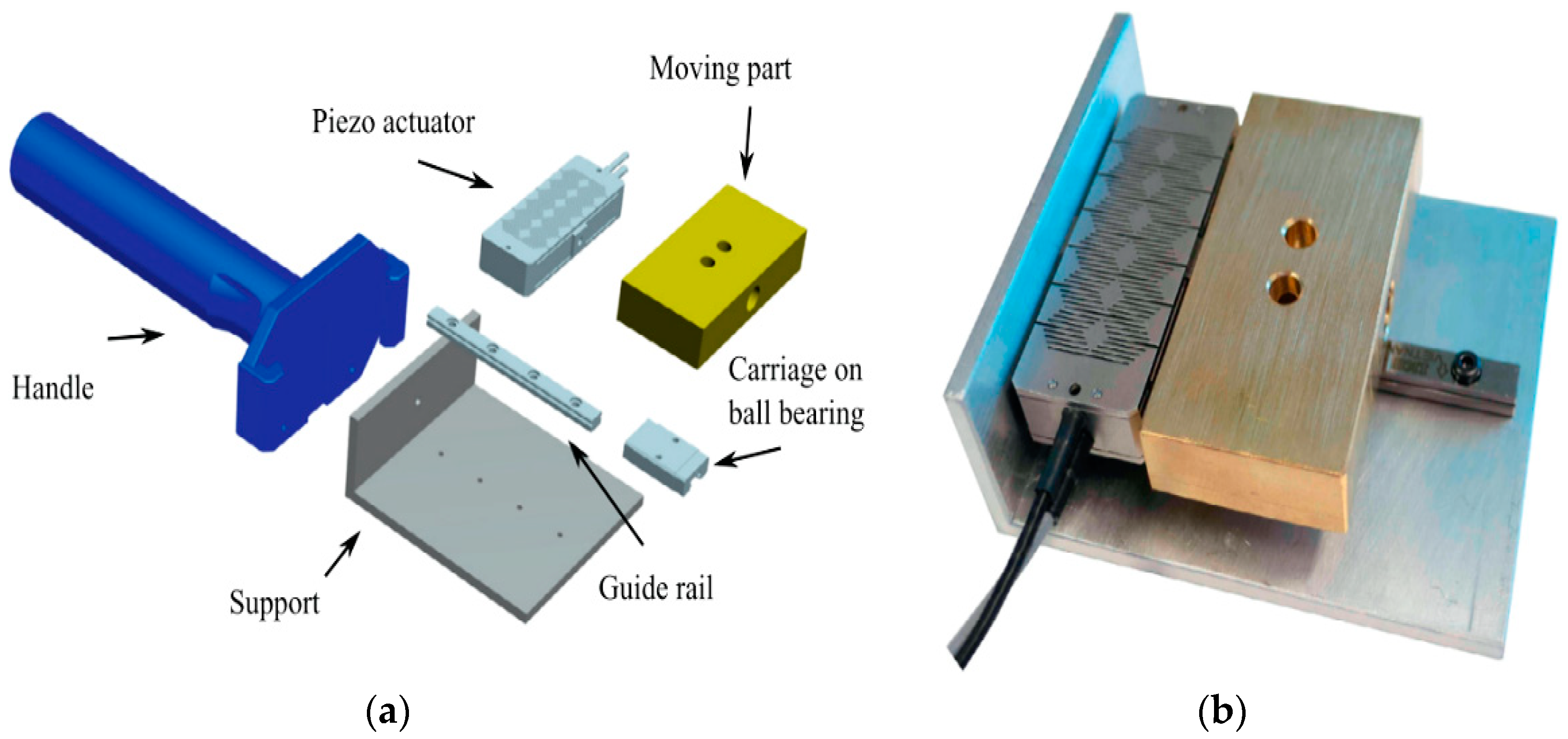
| Ungrounded inertial haptic interface [69] | Haptic devices | (1) Piezo actuator P-602-3SL; (1) Integrated position sensor; (1) 3- axis accelerometer MMA7361 | Piezoelectric | Force Feedback | Portable haptic device; Reduced mobile parts by implementing ball bearing |
| PPTs [76] | Haptic devices | Printed polymer transducers (PPTs) piezomembranes | Piezoelectric | Vibrotactile and acoustic haptic feedback | Free space haptic feedback based on ultrasound |
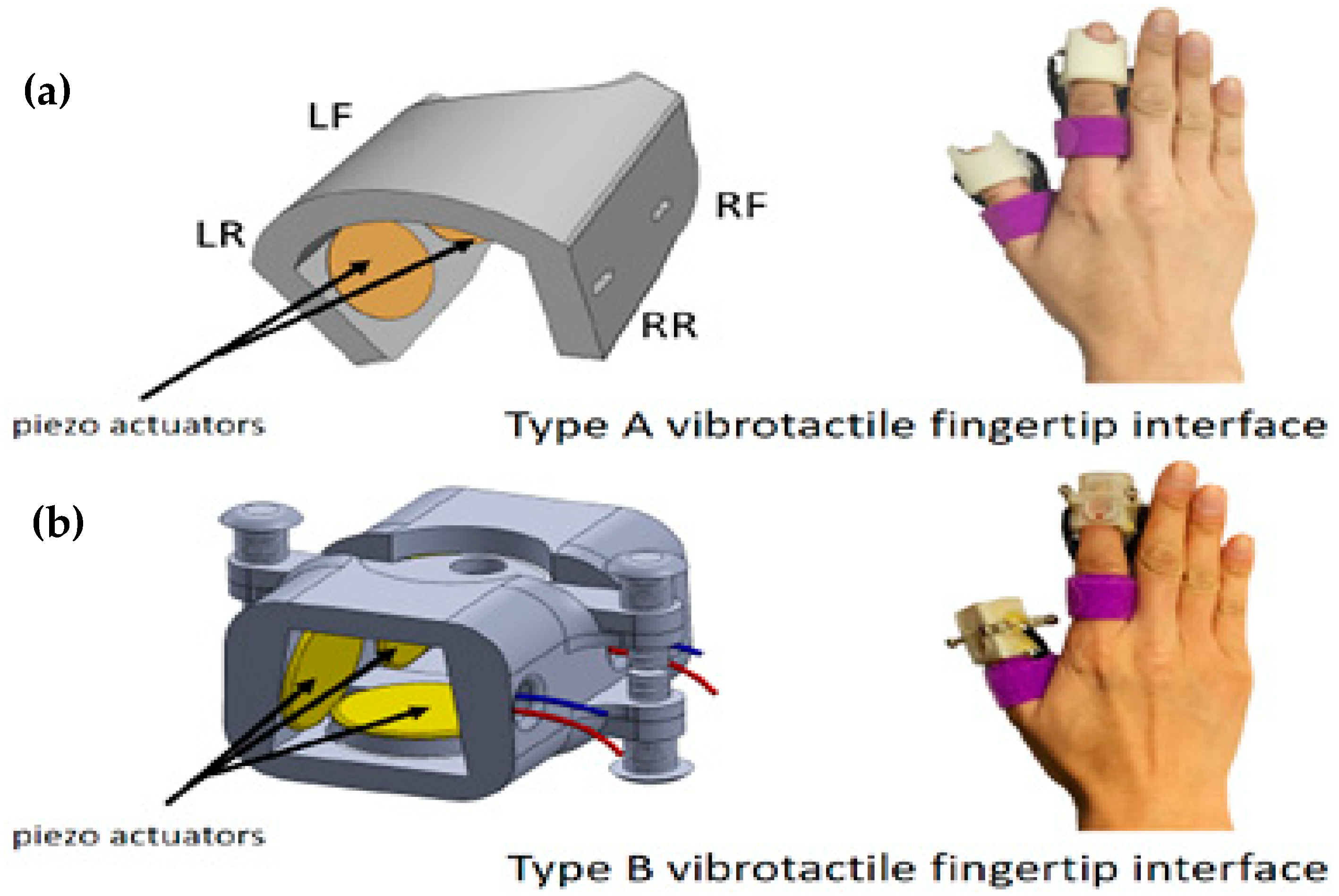
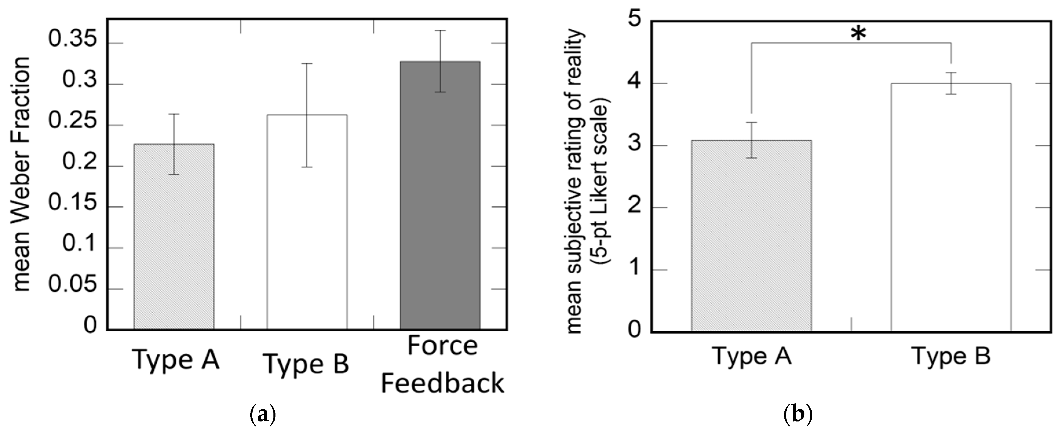
| Vibrotactile array fingertip [84] | VR object recognition and interaction | (4) Piezoelectric actuators | Piezoelectric | Vibrotactile Feedback | 3D VR interaction |
| Characteristic | Requirement |
|---|---|
| Monitoring hand movements | Up to 23 degrees of freedom (DoFs) are needed to effectively monitor hand gestures, including up to 4 DoFs for each finger (two for the first joint and one for each additional joint) and 3 DoFs for hand rotation. |
| Tactile Response | Tactile feedback improves both the bidirectional interaction with the manipulated item and, thus, the user experience. |
| Wearability | The device must be comfortable and simple to put on. |
| Dimension | The device might be created in various sizes or made adaptable. |
| Weight | The gloves should be light, often weighing between 50 and 300 g, as they are placed on the hand. |
| Power Source | The implementation of a low-power device is essential for this application. Energy-autonomous devices should be taken into account. |
| Wireless communication | A wireless connection (such Bluetooth or Wi-Fi-based) is recommended for remote machine control. |
| Work | N° of Sensors and Type | Processing Unit | Resulting Data/ Feedback | Future Applications and Improvements |
|---|---|---|---|---|
| B. Fang et al. [110] | (15) MPU9250 9-axis inertial and magnetic sensors | STM32F4 | ELM-based gestures recognition | Robotic teleoperation based on the gesture recognition |
| C. Luca et al. [117] | (3) Pressure sensors (3) Bending sensors | Atmega 328P | Finger movements detection | Clinical study testing |
| M.F. Simons et al. [119] | (1) Pressure pads made with silicone elastomer (1) Coiled SMA wires and Kapton tape for the armband | Atmega 328P | Mechanotactile stimulation | Testing on upper limb amputees to assess the device in a real application |
| W.V.I. Awantha et al. [125] | 8-layer jamming mechanism, (1) Inertial Measurement Unit (IMU) | Arduino Mega 2560 | Stiffening of jamming elements | Improve wearability; stiffness control; optimize tremor suppression using force assessment |
Disclaimer/Publisher’s Note: The statements, opinions and data contained in all publications are solely those of the individual author(s) and contributor(s) and not of MDPI and/or the editor(s). MDPI and/or the editor(s) disclaim responsibility for any injury to people or property resulting from any ideas, methods, instructions or products referred to in the content. |
© 2022 by the authors. Licensee MDPI, Basel, Switzerland. This article is an open access article distributed under the terms and conditions of the Creative Commons Attribution (CC BY) license (https://creativecommons.org/licenses/by/4.0/).
Share and Cite
De Fazio, R.; Mastronardi, V.M.; Petruzzi, M.; De Vittorio, M.; Visconti, P. Human–Machine Interaction through Advanced Haptic Sensors: A Piezoelectric Sensory Glove with Edge Machine Learning for Gesture and Object Recognition. Future Internet 2023, 15, 14. https://doi.org/10.3390/fi15010014
De Fazio R, Mastronardi VM, Petruzzi M, De Vittorio M, Visconti P. Human–Machine Interaction through Advanced Haptic Sensors: A Piezoelectric Sensory Glove with Edge Machine Learning for Gesture and Object Recognition. Future Internet. 2023; 15(1):14. https://doi.org/10.3390/fi15010014
Chicago/Turabian StyleDe Fazio, Roberto, Vincenzo Mariano Mastronardi, Matteo Petruzzi, Massimo De Vittorio, and Paolo Visconti. 2023. "Human–Machine Interaction through Advanced Haptic Sensors: A Piezoelectric Sensory Glove with Edge Machine Learning for Gesture and Object Recognition" Future Internet 15, no. 1: 14. https://doi.org/10.3390/fi15010014