
Estimation of the Band Gap of Carbon Nanotube Bundles
School of Science, Shanghai University, Shanghai 200444, China
*
Author to whom correspondence should be addressed.
Materials 2024, 17(7), 1530; https://doi.org/10.3390/ma17071530
Submission received: 21 February 2024
/
Revised: 24 March 2024
/
Accepted: 26 March 2024
/
Published: 27 March 2024
(This article belongs to the Topic Advances in Computational Materials Sciences)
Abstract
:The electronic structure of carbon nanotube bundles (CNTBs) can be a tough task for the routine first-principle calculation. The difficulty comes from several issues including the atomic structure, the boundary condition, and above all the very large number of atoms that makes the calculation quite cumbersome. In this work, we estimated the band gap of the CNTBs based on the results from single-walled carbon nanotubes (SWCNTs) under different deformations. The effects of squeezing, stretching, and torsion on the bands of SWCNTs were investigated through first-principle calculations, from which the band gaps of bundles were analyzed because the effects of these deformations were qualitatively independent when the distortions were small. Specifically, the gaps of (4,4) and (8,0) CNTBs under a reasonable torsional strength were predicted, wherein we were able to see metal–semiconductor and semiconductor–metal transitions, respectively. Such reversible mechanical modification of the conductivity may be helpful to the future band-gap engineering in nanoscale circuits.
1. Introduction
Since the discovery of carbon nanotubes (CNTs) [1,2], their excellent physical properties including strong structural stability and super high electron mobility have attracted a lot of attention of researchers [3,4,5,6,7,8]. Therefore, CNTs are very good candidates of the next generation of connecting wires for nanoscale circuits. For multi-walled carbon nanotubes (MWCNTs), their conductivity is mostly dominated by the outmost layer [9,10], meaning that SWCNTs turn out to be the irreducible fundamental components [11] in the circuits. The conductivity of SWCNTs at equilibrium is determined by one pair of parameters (n,m) of the structural configuration, namely, the chiral index. Recently, CNTBs have attracted researchers’ interests, and some efforts have been made regarding the mechanical resilience [12,13] and fracture patterns [14] under torsional strain. Singh [15] used CNTBs to build hybrid CMOS (complementary metal-oxide semiconductor)-compatible devices, among which the conductivity of CNTBs is one of the key issues to study. However, the routine first-principle methods such as density functional theory (DFT) or Hartree–Fock are not capable of handling a complex system like this from the atomic scale. Here, we treat the CNTBs as a whole group consisting of several deformed SWCNTs by analyzing each of them under particular deformation, wherein we were able to estimate the band gap change of the bundle during the deformation.
There are many feasible ways to tune the energy gap of carbon tubes. Some of them are chemical solutions such as element doping [16], vacancies doping [17,18,19], or atomic absorption [20,21]. As far as physical solutions are concerned, applying an external field has been reported to achieve this goal as well [22]. What is more, the mechanical way is also a possible choice. Due to their structural robustness, SWCNTs can withstand a relatively large degree of deformation before breaking down; hence, different types of mechanical deformation can also be utilized for band gap engineering. Some previous works verified that SWCNTs’ conductivity can be changed to a relatively large extent when they are radically compressed [23,24,25,26,27,28] or axially torqued [29,30], and sometimes a semiconductor–metal transition can even be observed.
In this paper, using density functional theory (DFT), we first investigated three types of deformations, namely, flattening, tension, and torsion, within a reasonable degree on six armchair or zigzag SWCNT samples. These different deformations showed different effects on the band gap tuning, depending on the tube chirality, which can be concluded as the following: metal SWCNTs are sensitive to torsion, which tends to open the gap, while they are reluctant to flattening and tension, and semiconducting SWCNTs’ gap can be closed by flattening, being sensitive to tension and torsion, but the trend depends on the particular chirality. When the distortion is small, the effects from different deformations are roughly independent of each other [31]; combining them together, we estimate the band gap of (4,4) and (8,0) CNTBs, and significant change can be seen from the straight bundle to the torsional.
2. Model and Methodology
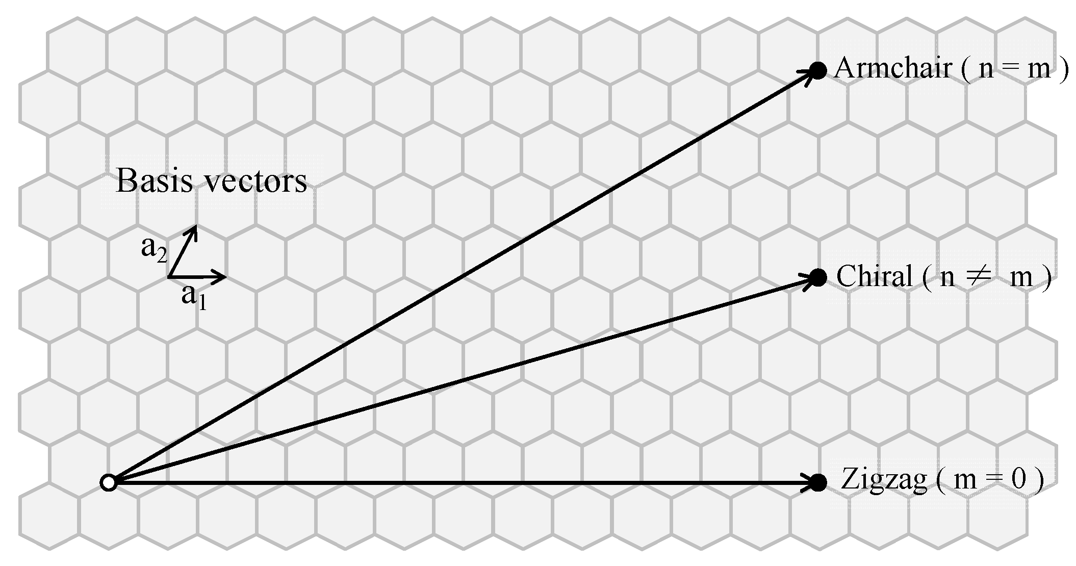
SWCNTs can be constructed by curling flat graphene and are usually represented by (n,m), which determines the SWCNT characteristics. As shown in Figure 1, the chiral indices (n,m) define the chiral vector (black arrows) that connects two carbon atoms in a graphene plane, and they are represented as na1 + ma2, where a1 and a2 are the basis vectors. The electronic structure of the deformed SWCNTs are evaluated with the density functional theory (DFT) method. The systems are optimized before the final band calculation, and we assume that external contact, which sometimes is necessary for the deformation, can be neglected when evaluating the bands. The details of the calculation setting are introduced as the following:
Projector augmented wave (PAW) pseudopotential is adopted to handle the effect of inner core electrons [32], and the Perdew–Burke–Ernzerhof (PBE) [33] functional is chosen to calculate the exchange-correlation energy. Plane wave basis has an energy cutoff of 300 eV; the k-point sampling (1 × 1 × kZ) is listed in Table 1, where the k-point is the quantum number of an electronic system moving in a crystal lattice, being a vector on the reciprocal space, and it is the sampling point in the concrete calculation. In plane of the cross-section, there is a large vacuum distance between two adjacent tubes; hence, they do not interact with each other, and setting the corresponding k-point sampling 1 is sufficient. Along the longitudinal axis, the k-point is set to a large integer kZ, and the exact number depends on the cell size. The electron density is converged with the criteria that the difference of total energy between two adjacent iterative steps is less than 10−4 eV. In structural optimization, conjugate gradient approximation [34] is used for the search of the energy minimum, where the iterations stop when the maximum force on each atom is less than 0.05 eV/Å. The model was constructed using Materials Studio [35], and the structure was optimized with DS-PAW in the Device Studio program [36].
3. Results and Discussion
In this section, we first check the effects of three different deformations on the band gap for SWCNTs. They are summarized separately in the following for simplicity.
3.1. Flattened Case
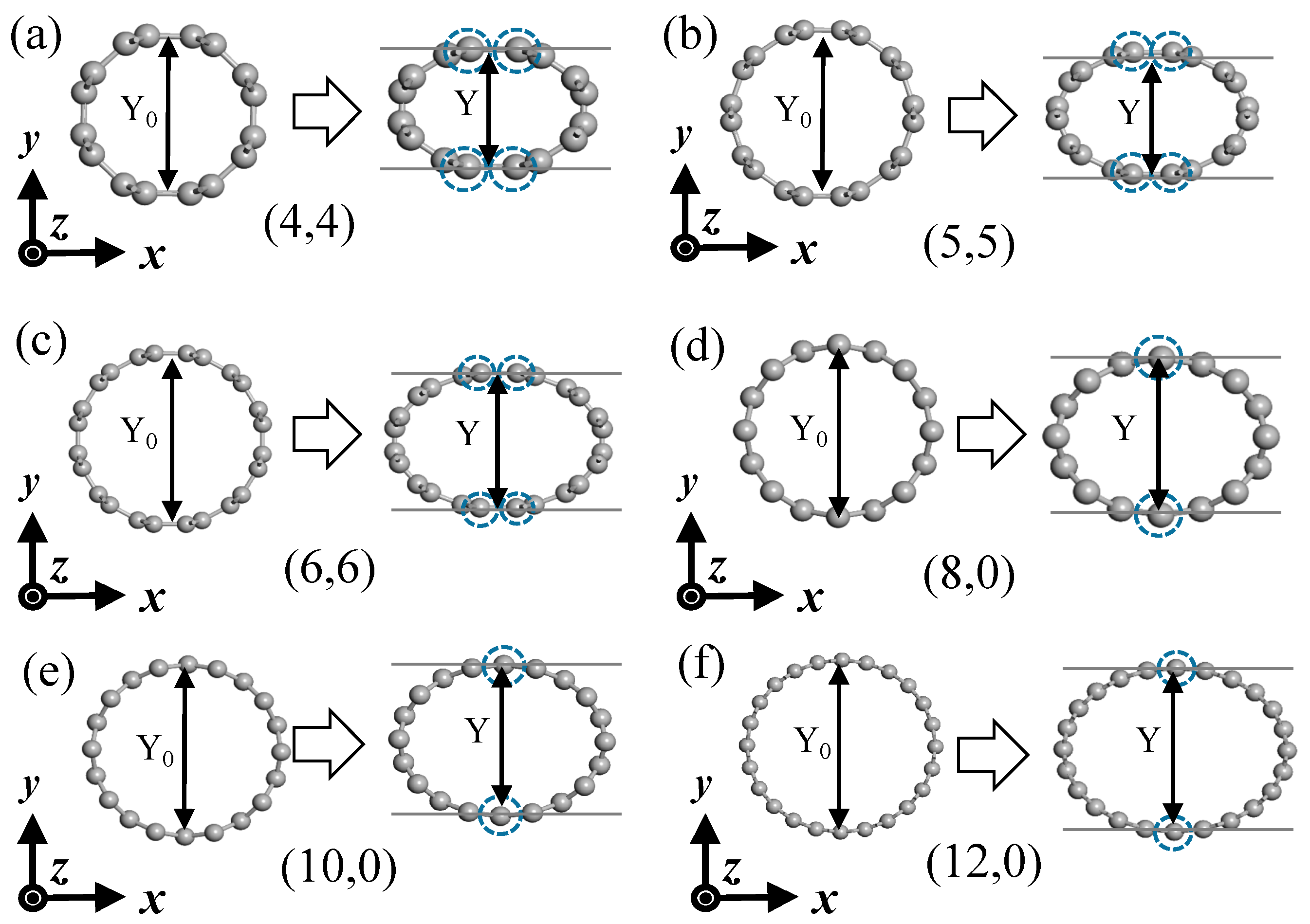
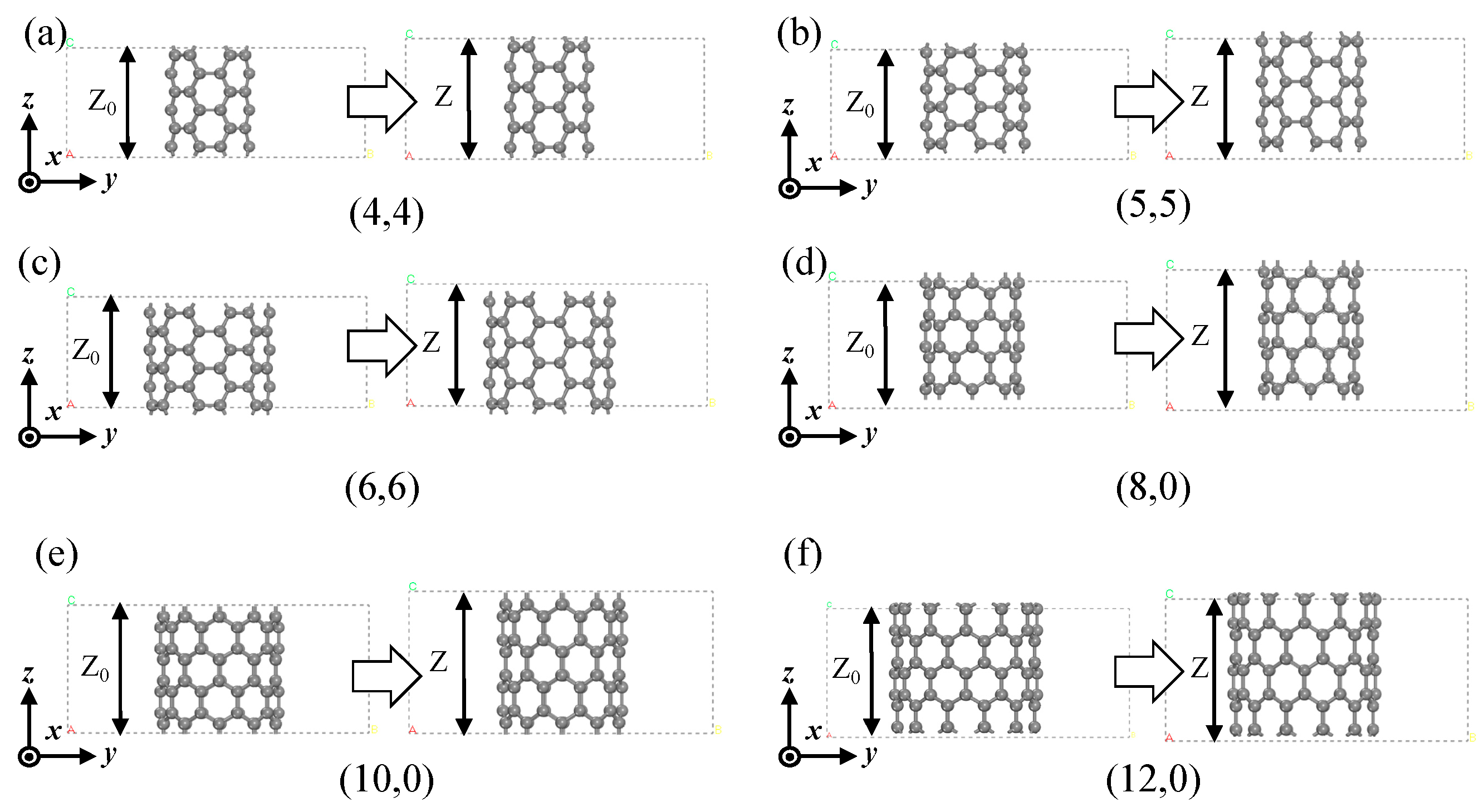
We used a dimensionless flatness parameter εyy − to quantify the flattening strength of SWCNTs, where Y0 is the diameter of the original tube and Y is the diameter of the deformed tube in the Y-axis direction, as shown in Figure 2. We moved the carbon atoms in the dashed circles in the y directions and fixed them; then, we relaxed the remaining part to obtain the final structure of the flattened case. The parameter εyy varied from 0.0 to 0.4 with intervals of 0.1 during this process. The corresponding external forces were considered practically reasonable according to the work by Mazzoni [23]; the force per unit length of the nanotube that was necessary to reach the insulator–metal transition was 7.4 N/m.
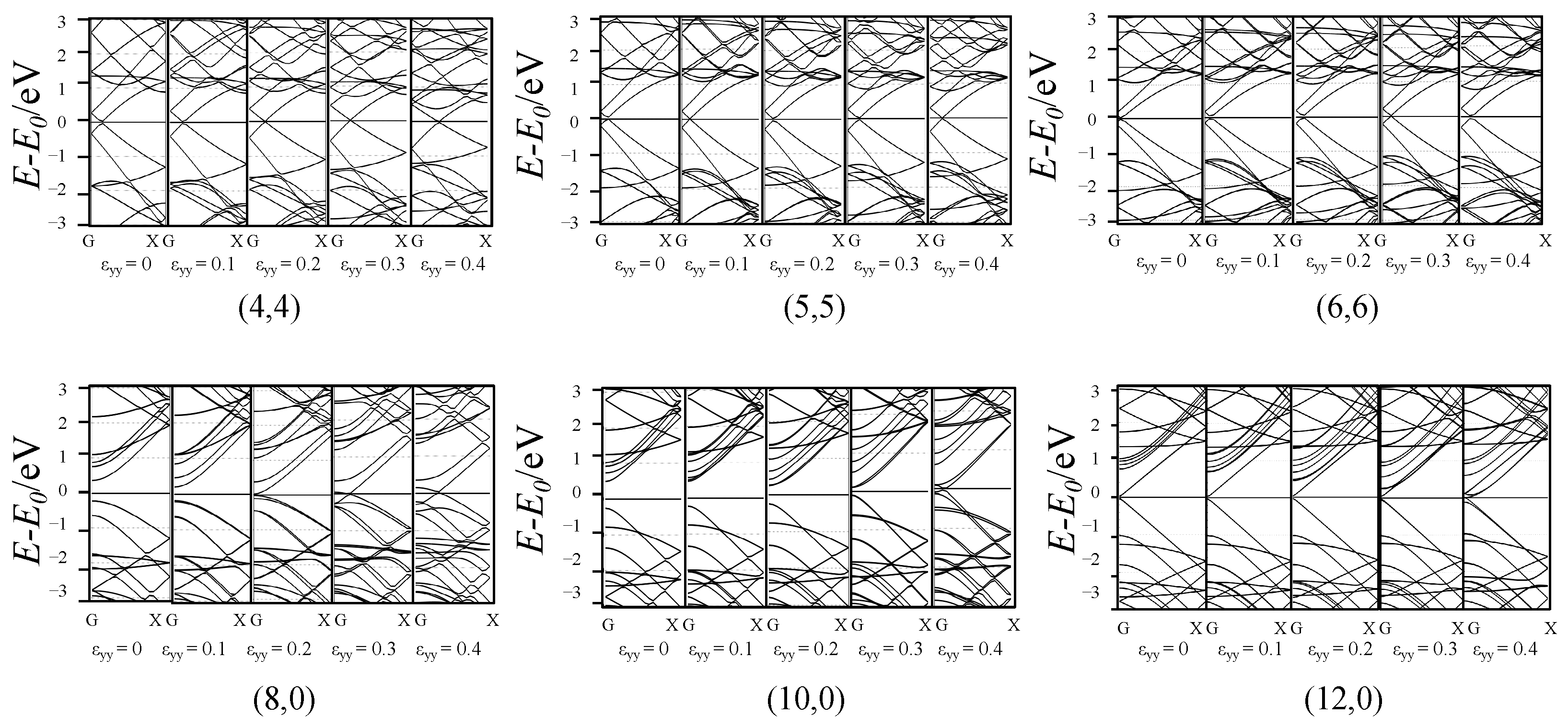
Figure 3 shows the change in the band structure of SWCNTs after flattening, where G and X represent two highly symmetric points in the Brillouin region of the carbon nanotube with the coordinates [0,0,0] and [0.5,0,0], respectively. The horizontal axis represents the k vector, and the vertical coordinate represents the difference between the electron energy and the Fermi level. During the deformation of flattening, for armchair SWCNTs, the crossing point of the bands near the Fermi level moved a little towards “X” point, and the effect of hybridization was stronger. For zigzag SWCNTs, the band gap of the semiconducting tubes tended to close during the deformation, and it was even able to be closed completely when εyy reached 0.2. The situation of the metallic tube did not change very much with a closed gap when εyy reached 0.4.
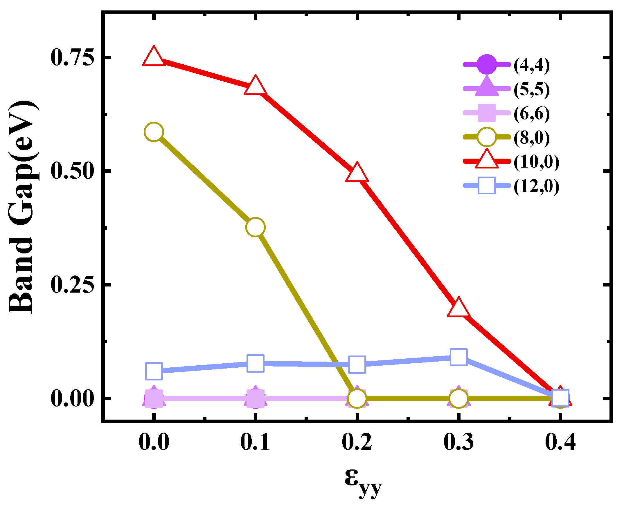
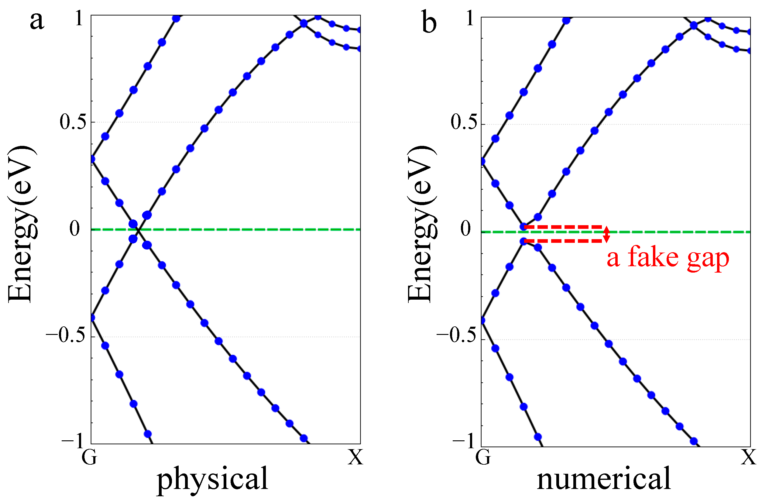
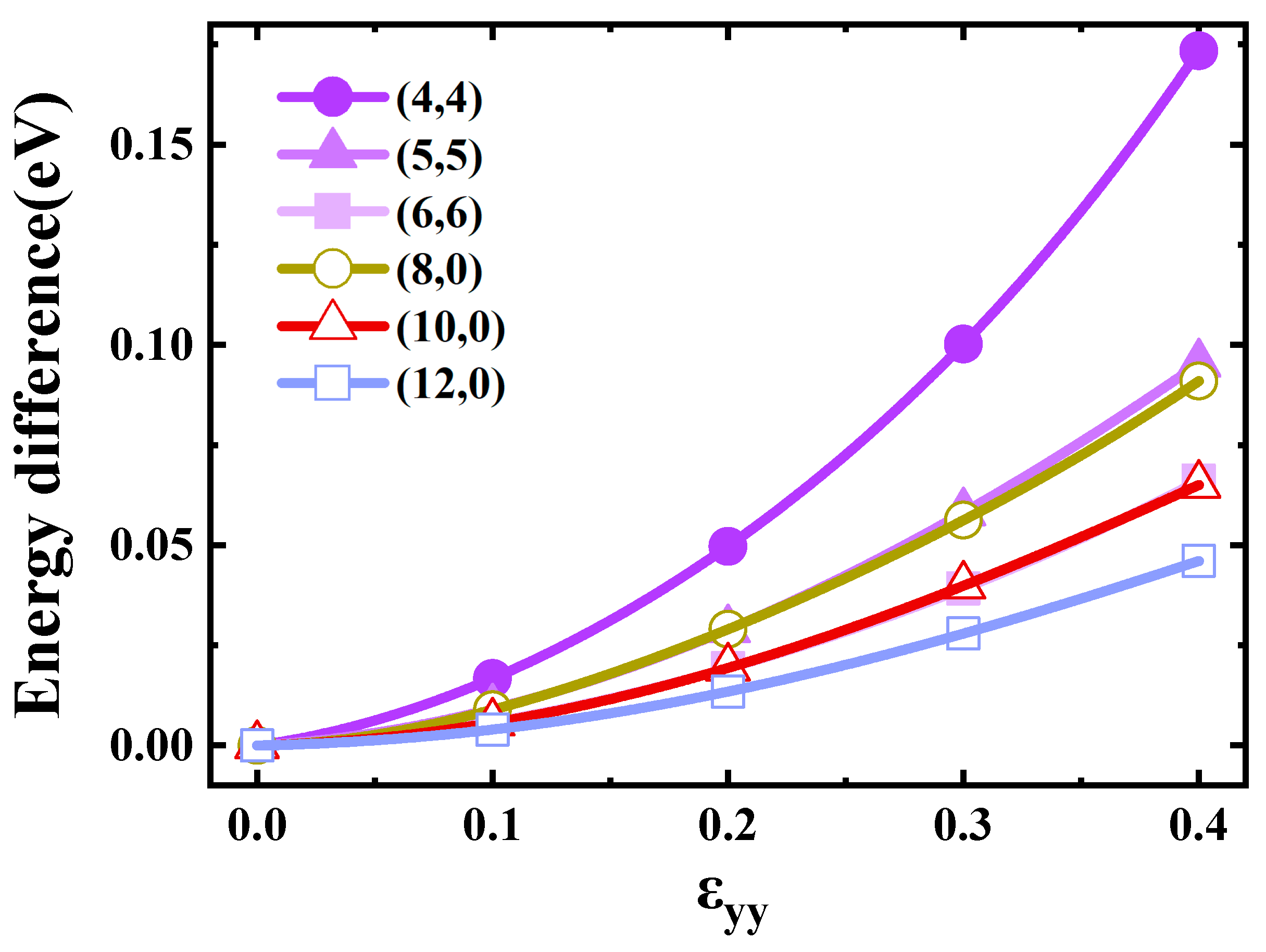
Figure 4 shows the effect of flattening on the SWCNTs’ band gap. We can see that the band gap of armchair SWCNTs had no significant change. There are some works [37,38] reporting that the armchair SWCNT has a finite band gap during the flattening process, whereas from the system symmetry, we can deduce that the small gap was not physical but numerical, as illustrated in Figure 5. This was the band structure of (4,4) SWCNTs at a flattening strength of 0.1. When the number of calculated K points is finite, a fake gap can be drawn by plotting software at the crossing point of the bands. The band gaps of (8,0) and (10,0) tubes showed a monotonic decrease when the flattening strength was increased, wherein the tubes changed from semiconductor-type carbon tubes to metal-type carbon tubes. The band gaps of (12,0) SWCNTs increased slightly and eventually decreased to 0 eV. In this process, the carbon tube was always metallic.
Figure 6 displays the fitting diagrams for the energy change of carbon atoms post-deformation. The deformation energy was obtained by counting the difference between the total energy of the different optimized systems and dividing the energy change by the number of atoms to obtain the average energy change per carbon atom. The energy curves were fitted with quartic polynomials. The choice of polynomial degrees in the fitting process is primarily dictated by the pursuit of accuracy, as established in the work of Kinoshita et al. [39]. With the increase in the flattening strength, the energy of all carbon atoms increased, among which the energy change of (4,4) was the most obvious. When the extrusion strength was 0.4, the energy of a carbon atom increased by 0.17 eV, and the increase of (12,0) was the least, wherein the energy of a carbon atom increased by 0.05 eV. If the diameter of the carbon tube is larger, the relative displacement of the carbon atoms will be smaller, that is, the energy change will be smaller.
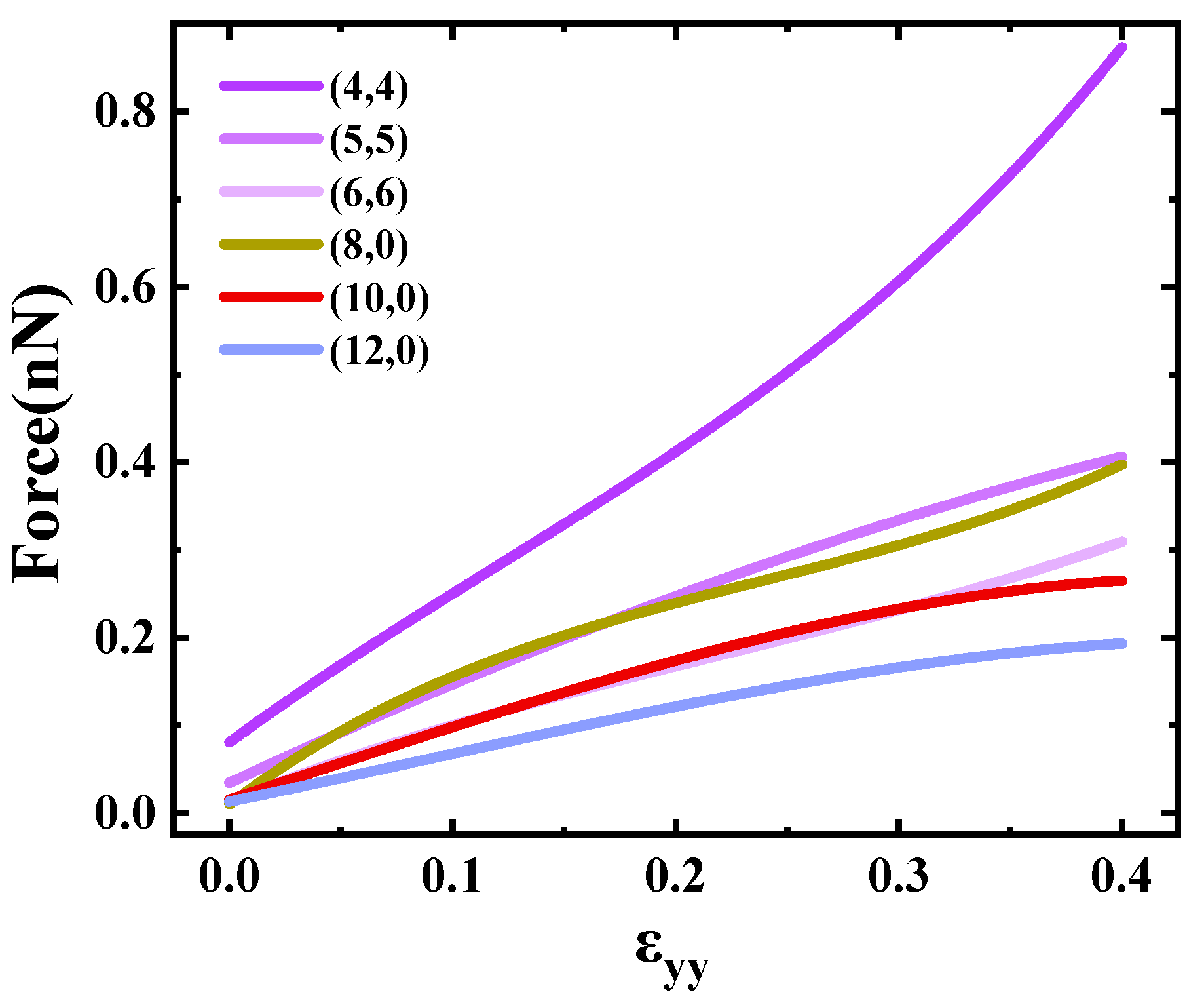
The force acting on the atom can be derived as the first-order derivative of the flattening curves [39]. The relationship between deformation strength and atomic force is presented in Figure 7. Observing Figure 7, it is evident that the force increased with the augmentation of deformation strength, and the force necessitated for flattening was comparatively smaller than that required for tension and torsion. It is noteworthy that for identical types of SWCNTs, the deformation force exhibited an increase with a decrease in diameter when subjected to the same deformation strength. For the (4,4) carbon tube, the force required for extrusion was the most: when the flattening strength was 0.4, the force required was 0.9 nN; for (12,0), the force required was the least: when the flattening strength was 0.4, the force required was 0.2 nN.
3.2. Tensioned Case
We used a dimensionless tensile degree εzz − to quantify the tensile strength of SWCNTs, where Z0 is the length of the original tube and Z is the length of the deformed tube in the Z-axis direction, as shown in Figure 8. The diagram shows six SWCNTs from the intrinsic carbon tube to a tensile strength of 0.1. In this paper, the parameter εzz varied from 0.0 to 0.1 with intervals of 0.025 during this process.
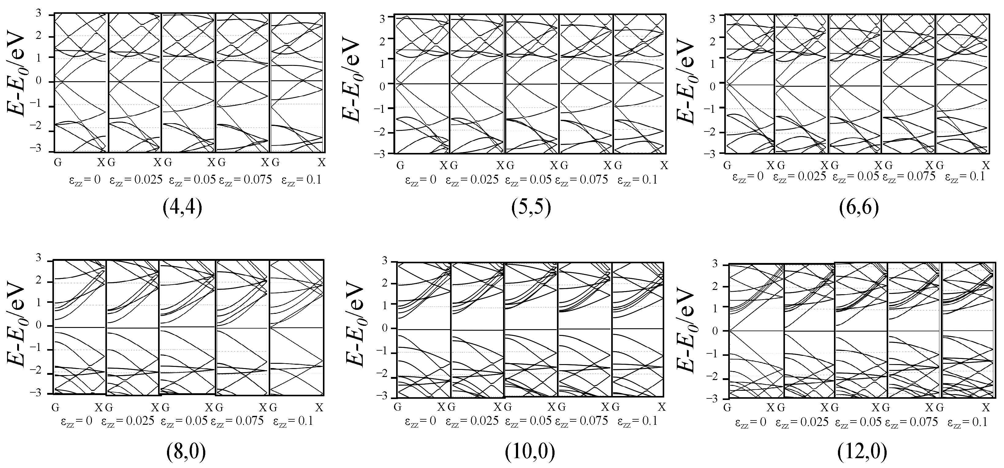
Figure 9 shows the tension effect on the band structure. For armchair SWCNTs, the crossing point of the bands near the Fermi level moved towards “X” point and the tube remained metallic. For zigzag SWCNTs, the band gap of the tube tended to close for semiconducting tubes and open for metallic ones during the deformation.
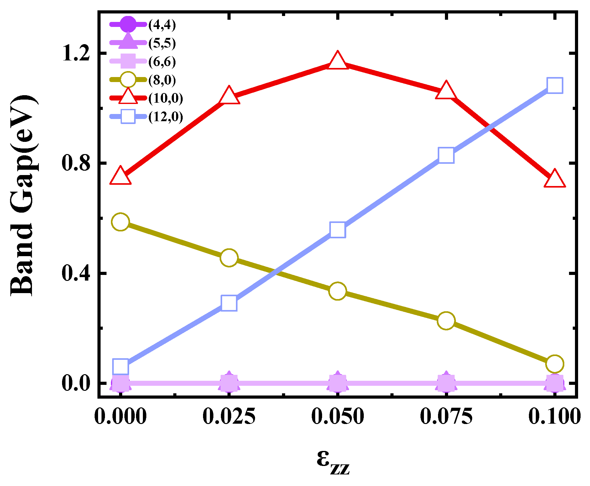
Figure 10 shows the effect of tension on the SWCNTs’ band gaps. The band gaps of armchair SWCNTs underwent no variation, while distinct band-gap behaviors were evident among the three types of zigzag SWCNTs. Specifically, the band gap of the (8,0) tube showed a monotonic decrease (0.6 eV→0.07 eV) with increasing tensile strength, wherein the (8,0) tube changed from a semiconductor-type carbon tube to a metal-type carbon tube. The (12,0) SWCNTs showed a monotonic increase (0.06 eV→1.0 eV) with increasing tensile strength, wherein the (12,0) tube changed from a metal-type carbon tube to a semiconductor-type carbon tube. For the (10,0) tube, the band gap’s trend tended to be a symmetric parabola with the peak at approximately (εzz = 0.05). The (10,0) tube was always a semiconductor carbon tube with increasing tensile strength, but the band gap reached its maximum value at (εzz = 0.05). The change of the band gap of the stretched carbon tube can be explained by the theory of Yang [31].
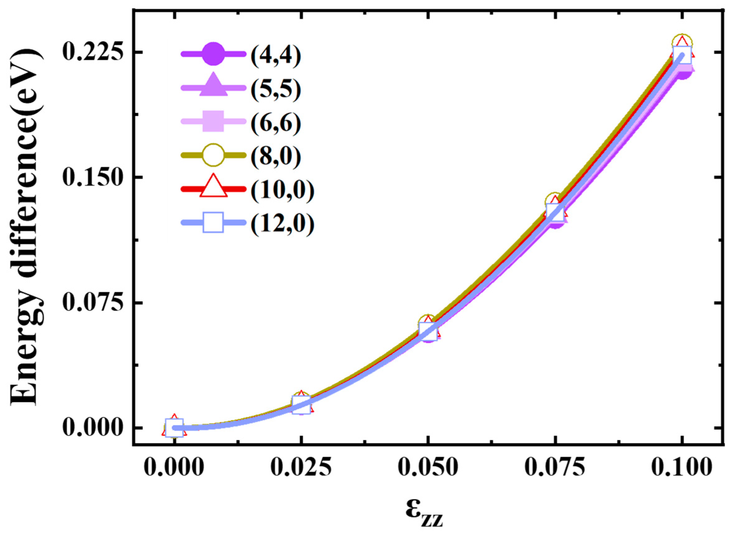
Figure 11 displays the fitting diagrams for the energy change of carbon atoms post-deformation. It can be seen from the figure that for all kinds of carbon tubes, the energy change after stretching was independent of the type of carbon tube, and the energy increased monotonically with the increase in tensile strength. The energy curves were fitted with cubic polynomials. For different kinds of SWCNTs, when the tensile strength increased from 0 to 0.1, the energy increased to about 0.22 eV.
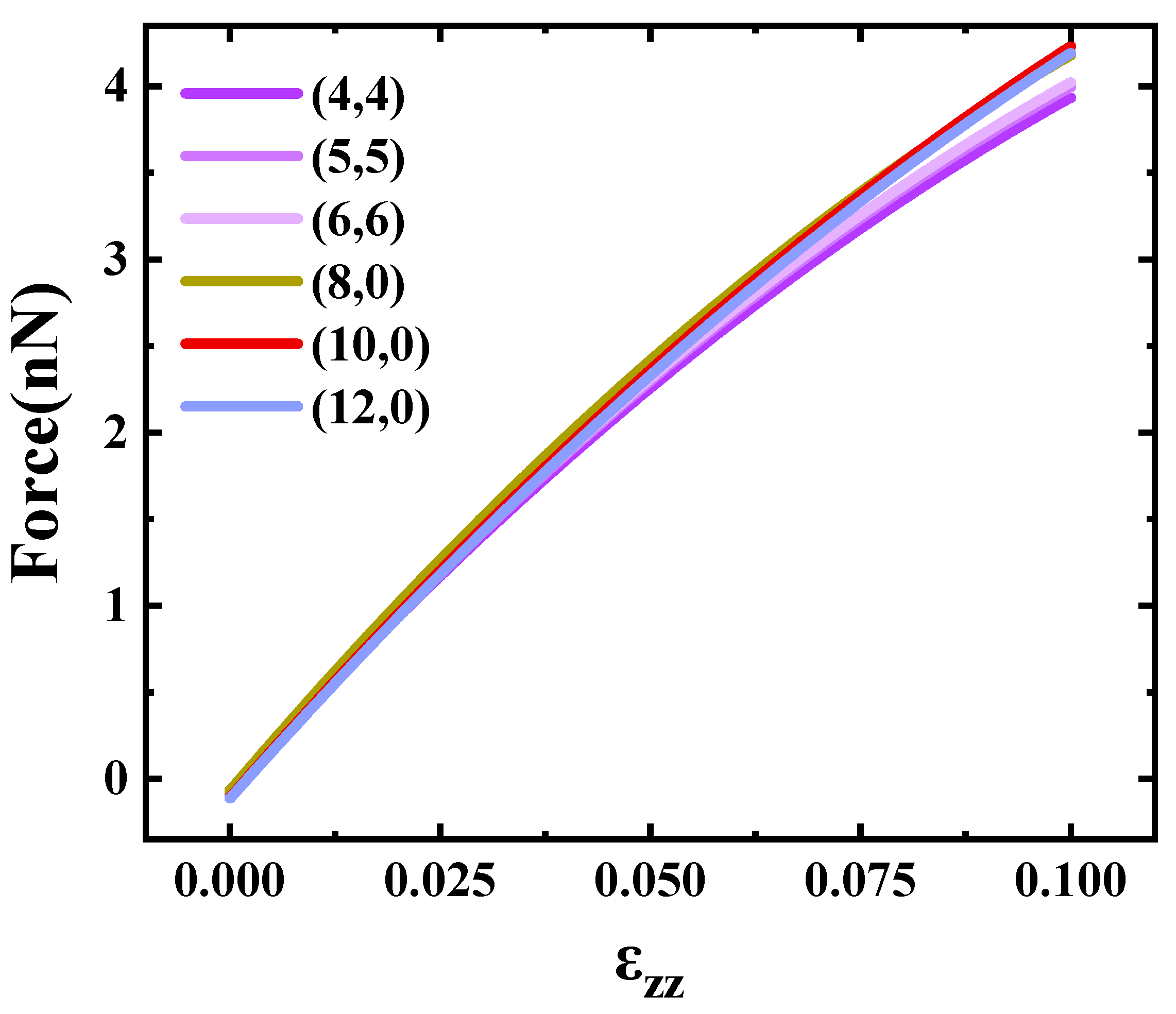
The force acting on the atom can be derived as the first-order derivative of the tension energy curves. The relationship between deformation strength and atomic force is presented in Figure 12. Observing Figure 12, it is evident that the force requirement increased with the augmentation of deformation strength; the force required for tension remained nearly independent of the carbon tube type, and we found that the carbon atoms moved very little in the xy plane. When the tensile strength was 0.1, the force on the carbon atom was about 4 nN, and the force change was almost the same for all types of carbon tubes.
3.3. Torsional Case
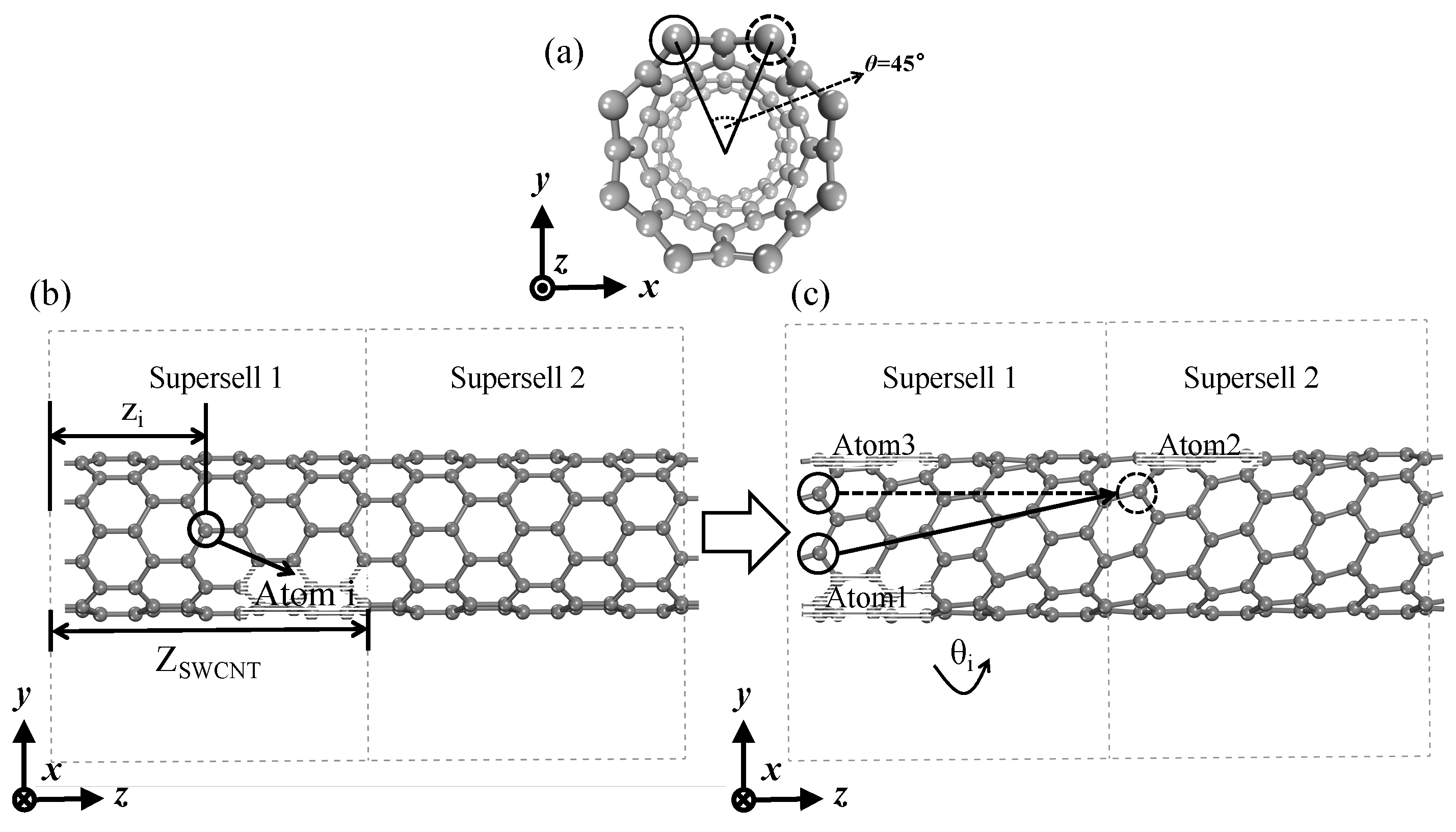
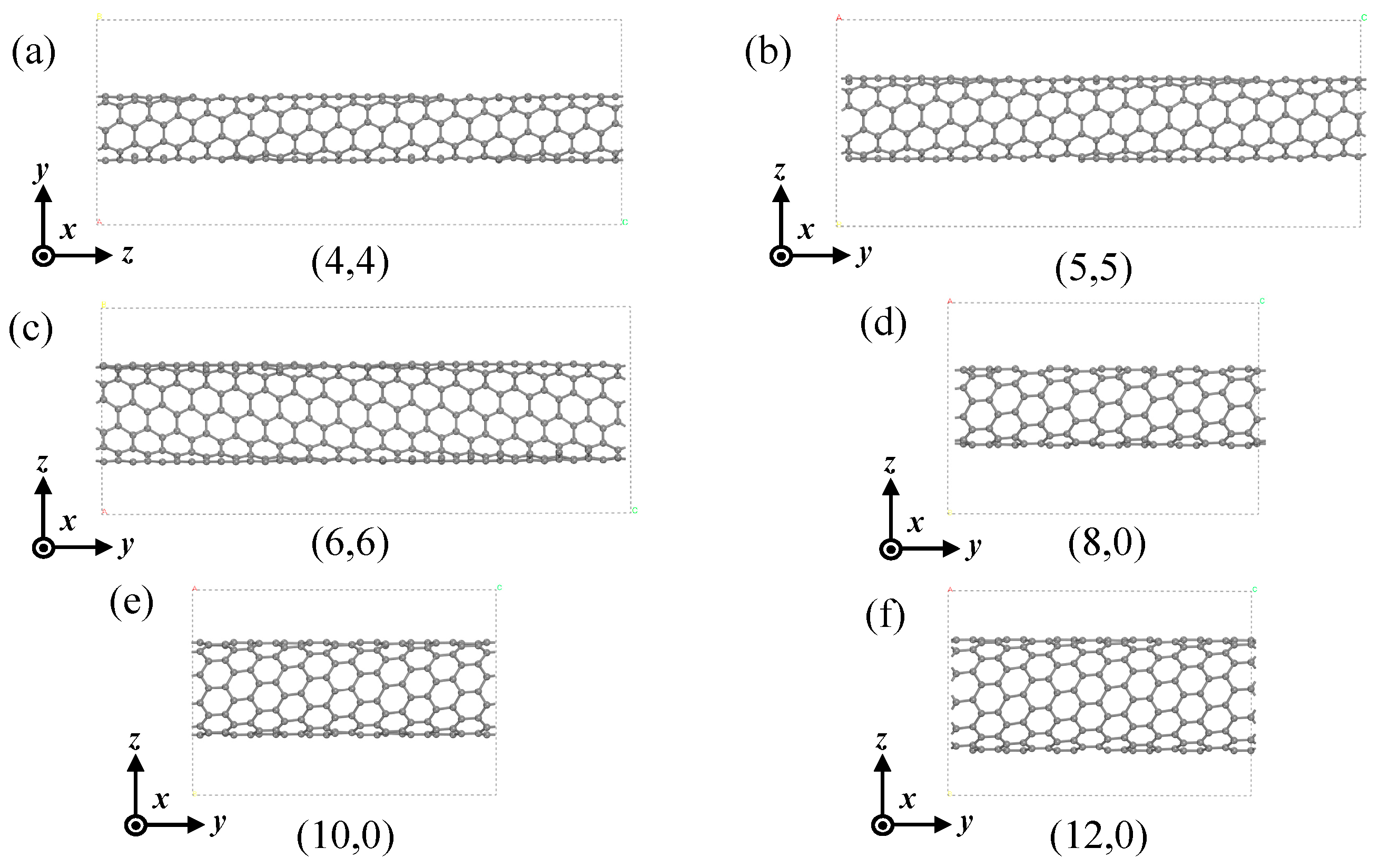
We used a torsional strength (rad/nm) to quantify the torsional strength of SWCNTs, where θ is the angle of twist, as shown in Figure 13a; for an (8,0) SWCNT, θ = 45°, and for an (n,m) SWCNT, θ = 360°/n. ZSWCNT represents the length of the supercell along the Z-axis, as shown in Figure 13b. Atom i underwent a central rotation of , resulting in the torsion model on the right (Figure 13b), where zi denotes the coordinate of atom i in the Z-axis direction. As shown in Figure 13c, atom 1 in supercell 1 was twisted to reach the position of atom 2 in supercell 2, which was equivalent to atom 3; the reason for this was to ensure that the model was infinitely cyclic and periodic in the Z-axis direction. Figure 14 shows six models of single-walled carbon nanotubes at the minimum torsional strength. To obtain the calculation results of a smaller torsional strength, more atoms need to be added. Due to the limited computational resources, the largest model that was able to be calculated in this paper is shown in the figure.
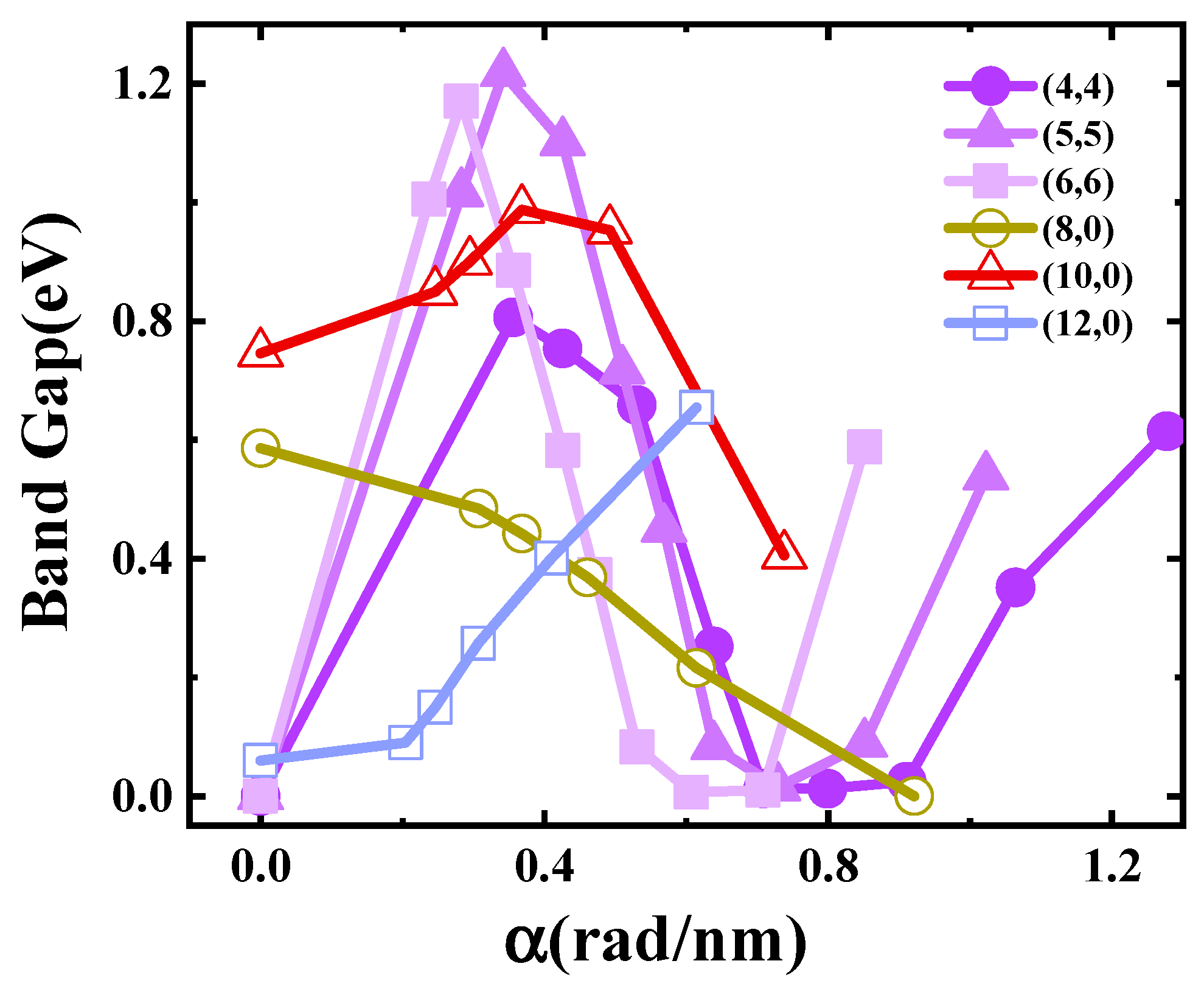
Figure 15 shows the effect of torsion on the SWCNTs’ band gap [40]. The band gaps of armchair tubes showed quite large fluctuations (metal→semiconductor→metal) with a rough period 0.8 rad/nm when the torsional strength increased from 0 rad/nm to 1.2 rad/nm. Semiconducting zigzag nanotubes (8,0) and (10,0) tended to have an overall decreasing trend in this region, while the (10,0) tube showed a small peak; when the strength reached about 0.4 rad/nm, the tubes changed from semiconductor-type carbon tubes to metal-type carbon tubes. Metallic zigzag (12,0) had an overall increasing trend, wherein the tube changed from a metal-type carbon tube to a semiconductor-type carbon tube.
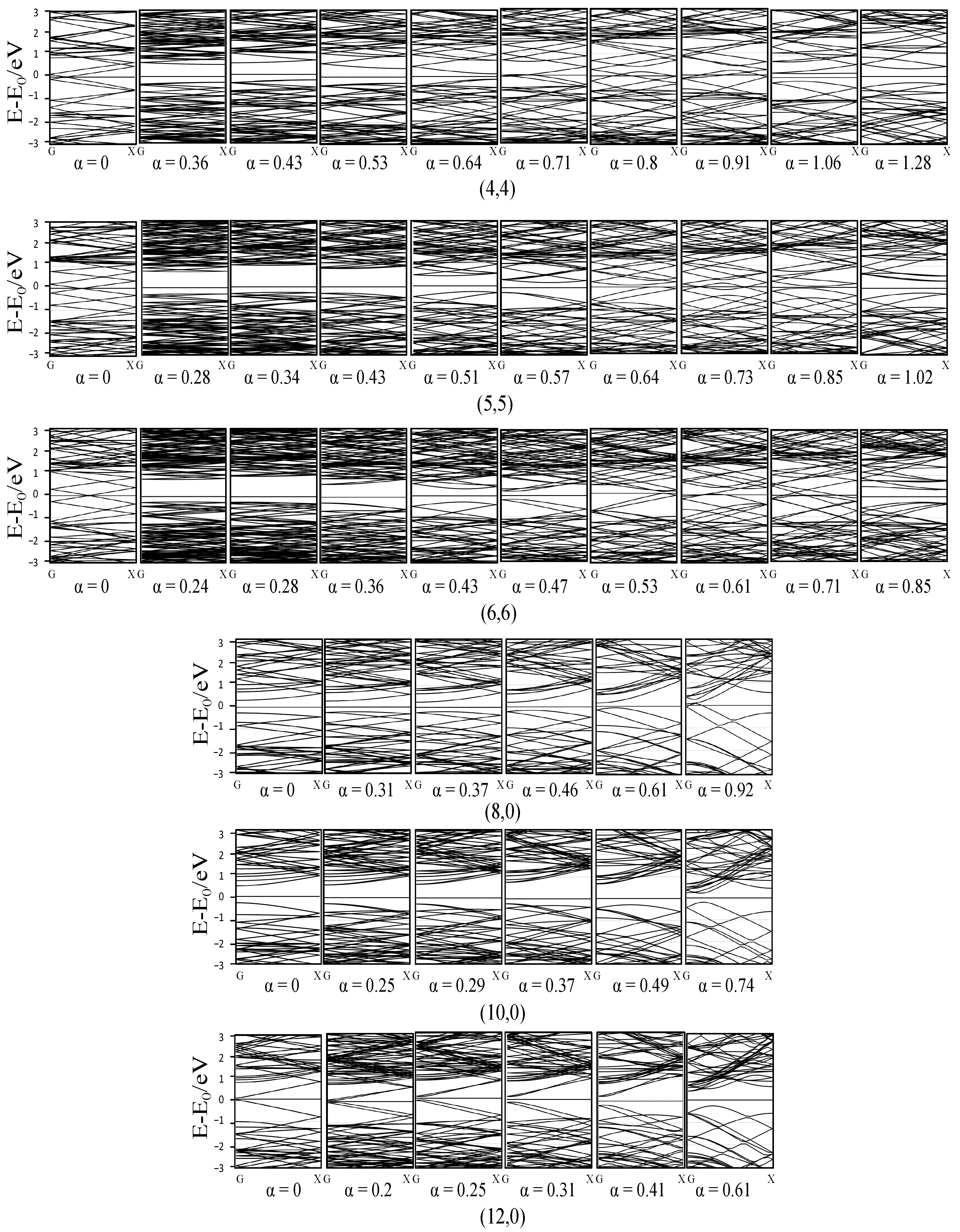
Figure 16 shows the effect of torsion on the SWCNTs’ band structure. We can see that different from flattening and tension, torsion did not change the band structure in a monotonic way, as the band structure will change significantly when the angle is very large. However, the monotonic trend can still be seen when the tube was slightly torqued, which can be summarized as the following: when the tube was torqued slightly, the gap tended to open for armchair tubes and metallic zigzag tubes and close for semiconducting zigzag ones.
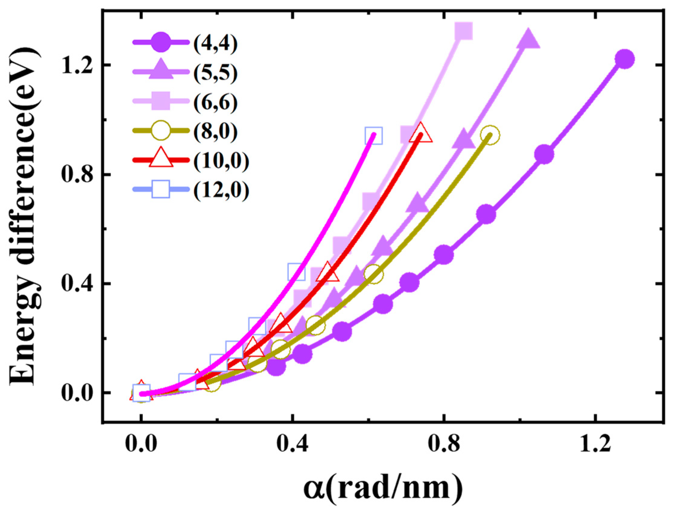
Figure 17 displays the fitting diagrams for the energy change of carbon atoms post-deformation. The torsion energy curves were fitted with quadratic polynomials. The deformation energy increased monotonically with the increase in torsional strength. For the same kind of carbon tube, the larger the diameter of single-walled carbon nanotubes, the more energy is required, because the energy change of a carbon tube is mainly due to the change in the distance between carbon atoms. When the same torsional strength was applied to the carbon tube, the larger the diameter of the carbon tube, the greater the relative displacement of the carbon atoms.
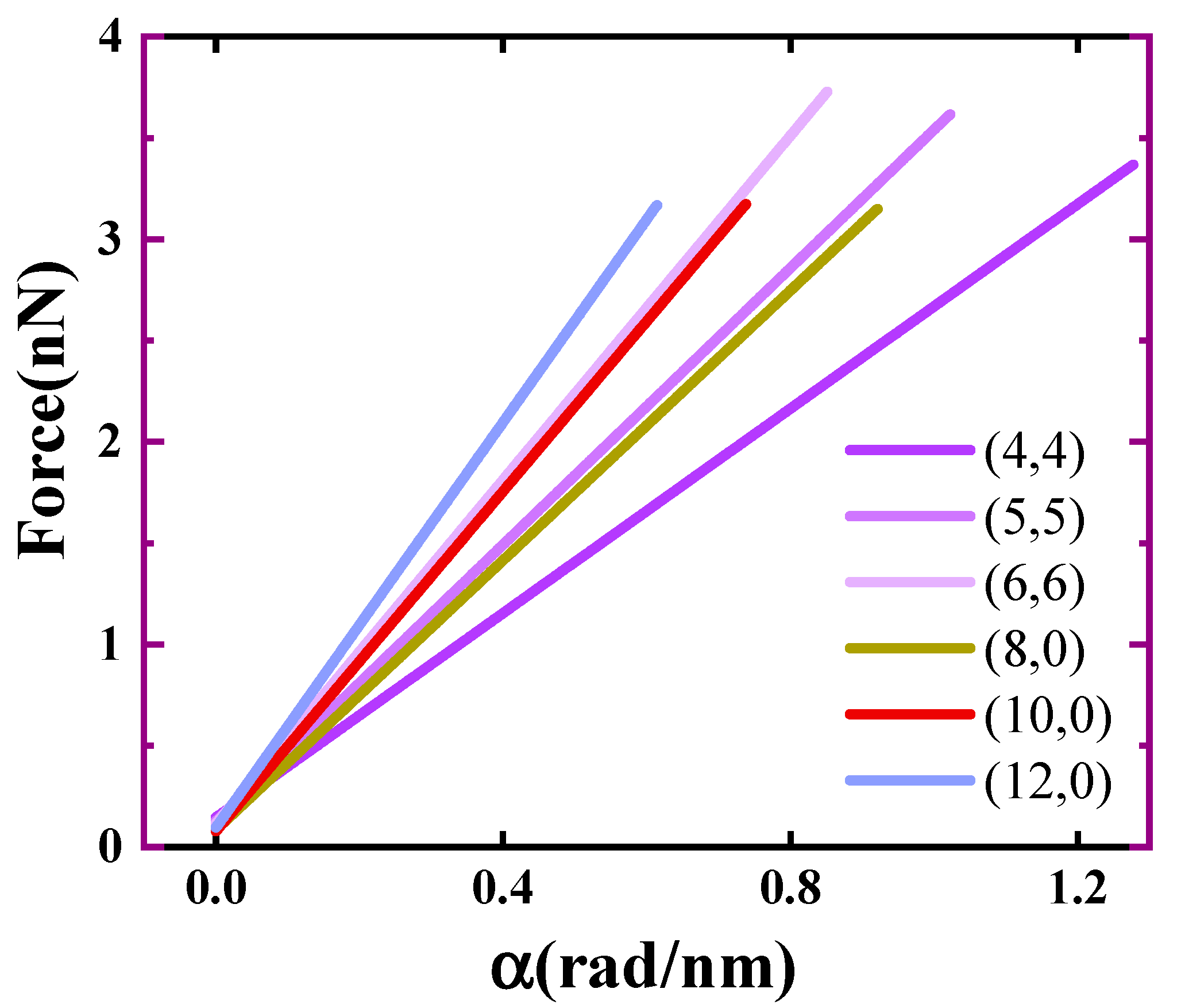
The torque was obtained from the first-order derivative of the torsion curve. The force on the carbon atom was determined by dividing the torque by the radius of the carbon tube. The relationship between deformation strength and atomic force is shown in Figure 18. Observing Figure 18, it is evident that the force requirement increased with the augmentation of deformation strength. The forces necessary for twisting SWCNTs are depicted, revealing that the twisting force increased with the diameter, indicating a direct relationship between diameter size and twisting force. For (4,4), when the torsional strength was 1.2 rad/nm, the force exerted on the carbon atom was about 3 nN, and for (12,0), when the torsional strength was 0.6 rad/nm, the force exerted on the carbon atom was about 3 nN.
3.4. CNTBs’ Discussion
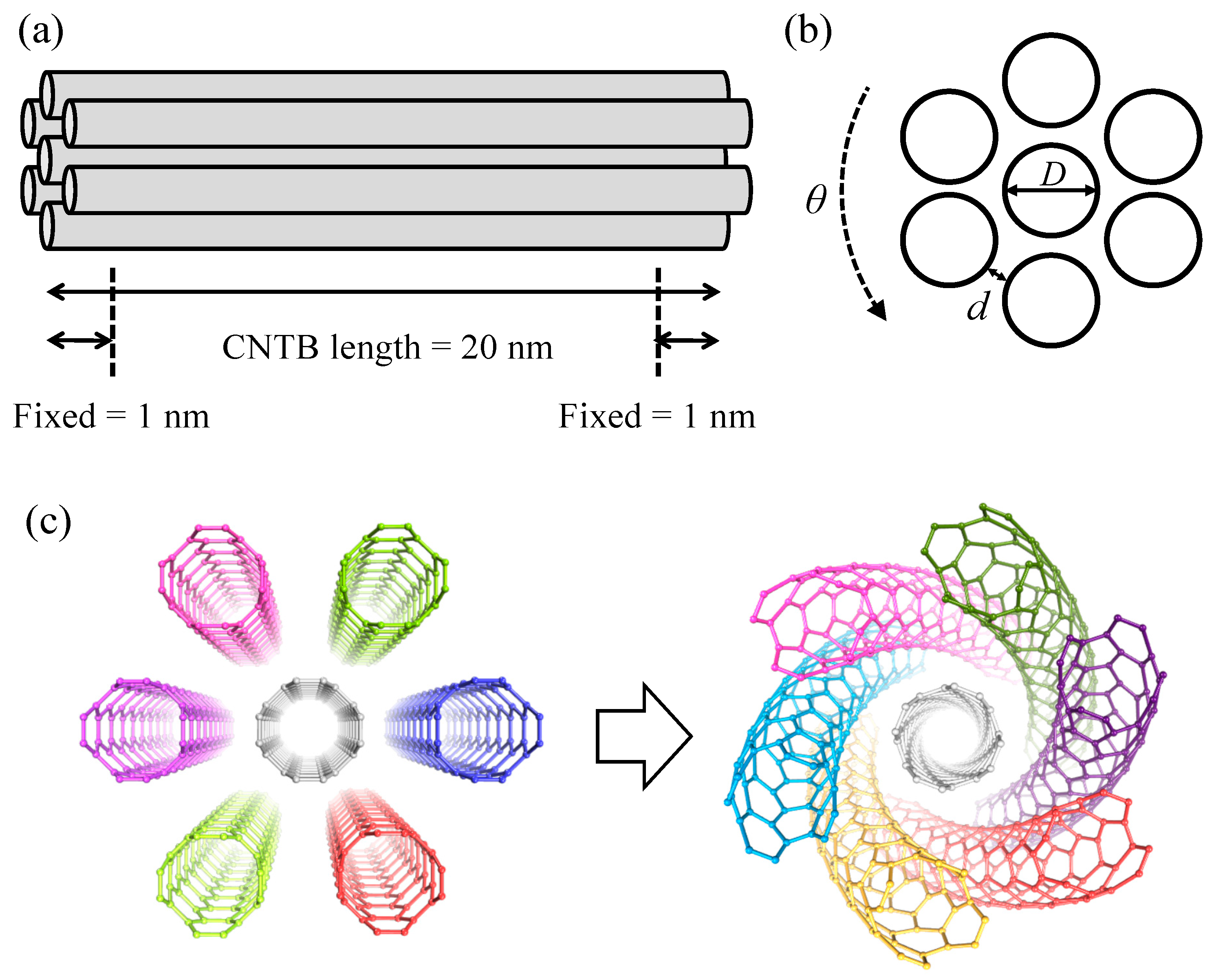
Then, we tried to estimate the band gap changes in CNTBs through mathematical models. In Figure 19a,b, the structural representation of CNTBs is shown, where seven SWCNTs were aligned together in a closed-packed shape. θ is the angle of twist. Figure 19c shows a diagram of the CNTBs after torsion. It should be emphasized that all seven carbon tubes were twisted. As a prototype, we chose the bundle 20 nm long with both ends fixed, shown in Figure 19. This construction method is referred to by Pereira et al. [14].
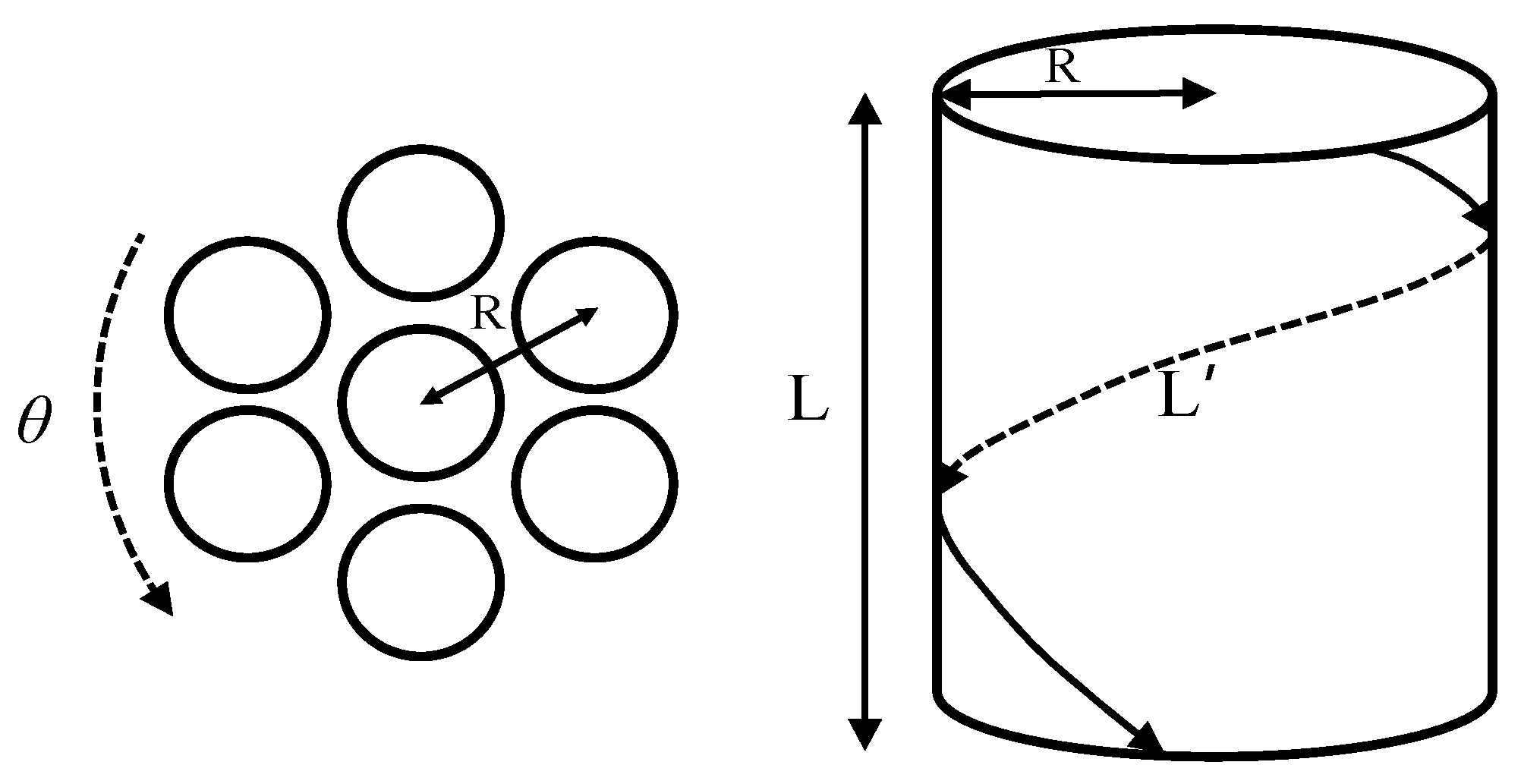
According to the dynamic simulation conducted [14], we think that the structural changes of SWCNTs in CNTBs after torsion at a small angle (0–0.6 (rad/nm)) can be represented by Figure 20. After torsioning the CNTBs, the length of the outer SWCNTs became the length of the helix of a cylinder with radius , where “D” is the diameter of the tube and “d” is the separation distance. The tensile strength of the outer SWCNTs is defined as
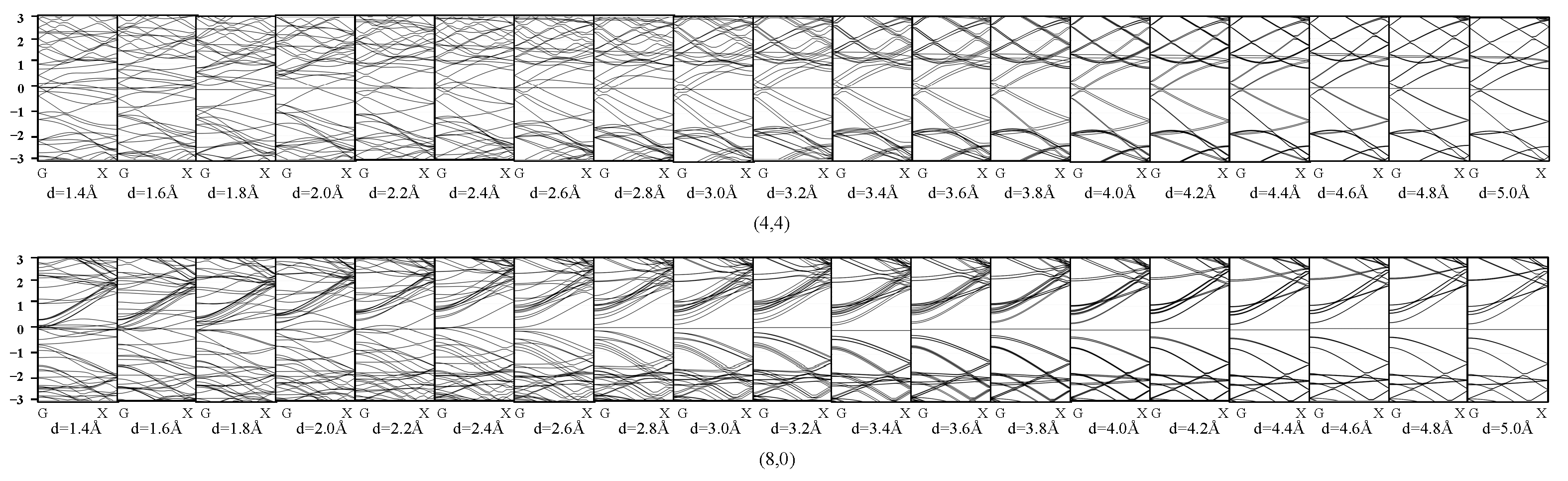
Packing of SWCNTs may lead to band-gap changes due to the interactions between tubes. If the SWCNTs are packed with a large external pressure, the adjacent tubes are in close proximity [41]. As shown in Figure 21, to analyze the effect of “d” on the band gap of CNTBs, we calculated the band gaps of two SWCNTs at distance “d”, where the “d” of (4,4) and (8,0) increased from 1.4 Å to 5 Å. The bundle structure in this paper was an isolate bunch of tubes torqued along the longitudinal axis, as illustrated in Figure 19 and Figure 20, which is somewhat different from the model by Okada et al. [42], where the bundle was crystalline. For an isolate bundle, our calculation showed that strong interaction pushed the outer tubes to the vacuum, and the corresponding distortion was alleviated. When the “d” was larger than 3.8 Å, the maximum force on each atom was less than 0.03 eV/Å, which is ignorable. In Figure 21, we can see that small inter-tube distance led to strong band hybridization, but when the value was greater than 3.8 Å, the interaction became weak and the effect was not obvious, especially regarding to the gap value. Therefore, for an isolate bunch of SWCNTs, from a qualitative point of view, we can set the inter-tube distance to 4 Å, where the distance did not change the band gap of (4,4), but for (8,0), the distance reduced the band gap by 0.0458 eV.
According to the results by Pereira et al. [14], bundles made from thin tubes did not have significant flattening deformation within a reasonable torsion. In this paper, under such a small torsional strength, the flattening effect can be neglected as well.
In such a bundle, the effective deformations of the outer tube include tension and torsion (the outer tube is bended as well, while the effect of slight bending is not considered), and inner tube is only torqued. It should be noted that the torsional strength of the outer tube is the same as that of the inner tube. We chose two tube bundles, (4,4) and (8,0), as the examples to represent metallic and semiconducting samples. Since tension tends to squeeze the gap of tube, the gap of the outer tube determines the gap of the bundle. Under small distortion, the effects of different deformations can be combined together according to the parametric model from the Huckel calculation [31].
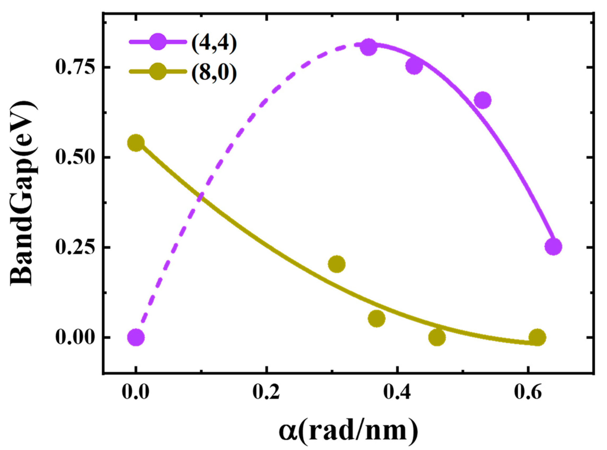
When the torsional strength of a bundle was in the range of [0, 0.6], the effects of three kinds of deformation on the band gap were as follows: flattening had no effect on the band gap; tension had no effect on the band gap of (4,4), while tension decreased the band gap of (8,0); torsion firstly increased the band gap of (4,4) and then reduced the band gap, and torsion monotonically decreased the band gap of (8,0). Distance had no effect on the band gap of (4,4), but for (8,0), the distance reduced the band gap by 0.0458 eV. The final results of the bundle gap are shown in Figure 22. In the torsional calculations, due to the limit of our structural configuration, the system size needed to be very large and beyond our computational ability to simulate a small torsion parameter. Therefore, the fitting can only be done with such a sparse sampling in the region [0, 0.3]. As the final result, we can see the semiconducting (8,0) bundle had a linear declination, while the metallic (4,4) bundle showed an approximate parabola, meaning that for both metallic or semiconducting SWCNTs, it is very possible to make a metal–semiconductor or semiconductor–metal transition by bundling them together at a certain distance and applying a certain degree of torsion.
4. Conclusions
This study undertook a comprehensive examination of the impact of three distinct deformation mechanisms on the band gap of carbon tubes: flattening, tension, and torsion. The band-gap changes under deformations for various SWCNTs were investigated by the first-principle method. The energy change of the carbon atom was analyzed, and the force change of the carbon atom was further obtained. Combining them together, the gap change of CNTBs (20 nm length) was estimated, and transitions between metal and semiconductor were able to be foreseen during the process of bundle formation.
Author Contributions
Conceptualization, J.-Z.C.; methodology, J.-Z.C.; software, Y.D.; validation, Y.D.; formal analysis, Y.D.; investigation, Y.D. and J.-Z.C.; resources, J.-Z.C.; data curation, Y.D.; writing—original draft, Y.D. and J.-Z.C.; writing—review and editing, Y.D. and J.-Z.C.; visualization, Y.D.; supervision, J.-Z.C.; project administration, J.-Z.C.; funding acquisition, J.-Z.C. All authors have read and agreed to the published version of the manuscript.
Funding
This research received no external funding.
Institutional Review Board Statement
Not applicable.
Informed Consent Statement
Not applicable.
Data Availability Statement
Data are contained within the article.
Conflicts of Interest
The authors declare no conflicts of interest.
References
- Iijima, S.; Ichihashi, T. Single-shell carbon nanotubes of 1-nm diameter. Nature 1993, 363, 603–605. [Google Scholar] [CrossRef]
- Iijima, S. Helical microtubules of graphitic carbon. Nature 1991, 354, 56–58. [Google Scholar] [CrossRef]
- Treacy, M.M.J.; Ebbesen, T.W.; Gibson, J.M. Exceptionally high Young’s modulus observed for individual carbon nanotubes. Nature 1996, 381, 678–680. [Google Scholar] [CrossRef]
- Krishnan, A.; Dujardin, E.; Ebbesen, T.W.; Yianilos, P.N.; Treacy, M.M.J. Young’s modulus of single-walled nanotubes. Phys. Rev. B 1998, 58, 14013–14019. [Google Scholar] [CrossRef]
- Takakura, A.; Beppu, K.; Nishihara, T.; Fukui, A.; Kozeki, T.; Namazu, T.; Miyauchi, Y.; Itami, K. Strength of carbon nanotubes depends on their chemical structures. Nat. Commun. 2019, 10, 3040. [Google Scholar] [CrossRef] [PubMed]
- Bai, Y.X.; Zhang, R.F.; Ye, X.; Zhu, Z.X.; Xie, H.H.; Shen, B.Y.; Cai, D.L.; Liu, B.F.; Zhang, C.X.; Jia, Z.; et al. Carbon nanotube bundles with tensile strength over 80 GPa. Nat. Nanotechnol. 2018, 13, 589–595. [Google Scholar] [CrossRef] [PubMed]
- Moon, S.; Song, W.; Kim, N.; Lee, J.S.; Na, P.S.; Lee, S.G.; Park, J.; Jung, M.H.; Lee, H.W.; Kang, K.H.; et al. Current-carrying capacity of double-wall carbon nanotubes. Nanotechnology 2007, 18, 235201. [Google Scholar] [CrossRef]
- Ahlskog, M.; Herranen, O.; Johansson, A.; Leppaniemi, J.; Mtsuko, D. Electronic transport in intermediate sized carbon nanotubes. Phys. Rev. B 2009, 79, 155408. [Google Scholar] [CrossRef]
- Coskun, U.C.; Wei, T.-C.; Vishveshwara, S.; Goldbart, P.M.; Bezryadin, A. h/e Magnetic Flux Modulation of the Energy Gap in Nanotube Quantum Dots. Science 2004, 304, 1132–1134. [Google Scholar] [CrossRef]
- Frank, S.; Poncharal, P.; Wang, Z.L.; Heer, W.A.d. Carbon Nanotube Quantum Resistors. Science 1998, 280, 1744–1746. [Google Scholar] [CrossRef]
- Fischer, J.E.; Johnson, A.T. Electronic properties of carbon nanotubes. Curr. Opin. Solid State Mater. Sci. 1999, 4, 28–33. [Google Scholar] [CrossRef]
- Wei, H.Q.; Ting, H.Z.J.; Gong, Y.J.; Lue, C.F.; Glukhova, O.E.; Zhan, H.F. Torsional Properties of Bundles with Randomly Packed Carbon Nanotubes. Nanomaterials 2022, 12, 760. [Google Scholar] [CrossRef] [PubMed]
- Asadollahi, D.; Shariati, M. Investigation of shear forces in twisted carbon nanotube bundles using a structural mechanics approach. Acta Mech. 2021, 232, 2425–2441. [Google Scholar] [CrossRef]
- Pereira, M.L.; Oliveira, T.D.; Monteiro, F.F.; Da Cunha, W.F.; Neto, P.H.D.; Ribeiro, L.A. Torsional fracture of carbon nanotube bundles: A reactive molecular dynamics study. Phys. Chem. Chem. Phys. 2022, 24, 15068–15074. [Google Scholar] [CrossRef] [PubMed]
- Singh, R.S.; Takagi, K.; Aoki, T.; Moon, J.H.; Neo, Y.; Iwata, F.; Mimura, H.; Moraru, D. Precise Deposition of Carbon Nanotube Bundles by Inkjet-Printing on a CMOS-Compatible Platform. Materials 2022, 15, 4935. [Google Scholar] [CrossRef] [PubMed]
- Azam, M.A.; Alias, F.M.; Tack, L.W.; Seman, R.; Taib, M.F.M. Electronic properties and gas adsorption behaviour of pristine, silicon-, and boron-doped (8,0) single-walled carbon nanotube: A first principles study. J. Mol. Graph. Model. 2017, 75, 85–93. [Google Scholar] [CrossRef]
- Kang, Y.J.; Kim, Y.H.; Chang, K.J. Electrical transport properties of nanoscale devices based on carbon nanotubes. Curr. Appl. Phys. 2009, 9, S7–S11. [Google Scholar] [CrossRef]
- Khademhosseini, V.; Dideban, D.; Ahmadi, M.T.; Ismail, R. The impact of vacancy defects on the performance of a single-electron transistor with a carbon nanotube island. J. Comput. Electron. 2019, 18, 428–435. [Google Scholar] [CrossRef]
- Fagan, S.B.; da Silva, L.B.; Mota, R. Ab initio study of radial deformation plus vacancy on carbon nanotubes: Energetics and electronic properties. Nano Lett. 2003, 3, 289–291. [Google Scholar] [CrossRef]
- Berd, M.; Moussi, K.; Aouabdia, Y.; Benchallal, L.; Chahi, G.; Kahouadji, B. From metallic to semiconductor conversion of single-walled carbon nanotubes by chlorination. Chem. Phys. Lett. 2021, 781, 138988. [Google Scholar] [CrossRef]
- Sinha, S.; Bandyopadhyay, J. Metal to semiconductor conversion by hydrogenation in guanine functionalized SWCNT. Microsyst. Technol.-Micro-Nanosyst.-Inf. Storage Process. Syst. 2019, 25, 1863–1874. [Google Scholar] [CrossRef]
- Shtogun, Y.V.; Woods, L.M. Electronic Structure Modulations of Radially Deformed Single Wall Carbon Nanotubes under Transverse External Electric Fields. J. Phys. Chem. C 2009, 113, 4792–4796. [Google Scholar] [CrossRef]
- Mazzoni, M.; Chacham, H. Bandgap closure of a flattened semiconductor carbon nanotube: A first-principles study. Appl. Phys. Lett. 2000, 76, 1561–1563. [Google Scholar] [CrossRef]
- Peng, S.; Cho, K. Nano electro mechanics of semiconducting carbon nanotube. J. Appl. Mech. Trans. Asme 2002, 69, 451–453. [Google Scholar] [CrossRef]
- Shtogun, Y.V.; Woods, L.M. Electronic and magnetic properties of deformed and defective single wall carbon nanotubes. Carbon 2009, 47, 3252–3262. [Google Scholar] [CrossRef]
- Shan, B.; Lakatos, G.W.; Peng, S.; Cho, K.J. First-principles study of band-gap change in deformed nanotubes. Appl. Phys. Lett. 2005, 87, 173109. [Google Scholar] [CrossRef]
- Nishidate, K.; Hasegawa, M. Universal band gap modulation by radial deformation in semiconductor single-walled carbon nanotubes. Phys. Rev. B 2008, 78, 195403. [Google Scholar] [CrossRef]
- Gulseren, O.; Yildirim, T.; Ciraci, S.; Kilic, C. Reversible band-gap engineering in carbon nanotubes by radial deformation. Phys. Rev. B 2002, 65, 155410. [Google Scholar] [CrossRef]
- Kato, K.; Koretsune, T.; Saito, S. Energetics and electronic properties of twisted single-walled carbon nanotubes. Phys. Rev. B 2012, 85, 115448. [Google Scholar] [CrossRef]
- Vercosa, D.G.; Barros, E.B.; Souza, A.G.; Mendes, J.; Samsonidze, G.G.; Saito, R.; Dresselhaus, M.S. Torsional instability of chiral carbon nanotubes. Phys. Rev. B 2010, 81, 165430. [Google Scholar] [CrossRef]
- Yang, L.; Han, J. Electronic structure of deformed carbon nanotubes. Phys. Rev. Lett. 2000, 85, 154–157. [Google Scholar] [CrossRef] [PubMed]
- Blochl, P.E. Projector augmented-wave method. Phys. Rev. B 1994, 50, 17953–17979. [Google Scholar] [CrossRef] [PubMed]
- Perdew, J.P.; Burke, K.; Ernzerhof, M. Generalized Gradient Approximation Made Simple. Phys. Rev. Lett. 1996, 77, 3865. [Google Scholar] [CrossRef] [PubMed]
- Langreth, D.C.; Mehl, M.J. Beyond the local-density approximation in calculations of ground-state electronic properties. Phys. Rev. B 1983, 28, 1809–1834. [Google Scholar] [CrossRef]
- Clark, S.J.; Segall, M.D.; Pickard, C.J.; Hasnip, P.J.; Probert, M.J.; Refson, K.; Payne, M.C. First principles methods using CASTEP. Z. Krist. 2005, 220, 567–570. [Google Scholar] [CrossRef]
- Hongzhiwei Technology. Available online: https://cloud.hzwtech.com (accessed on 1 September 2023).
- Najim, A.; Bajjou, O.; Bakour, A.; Rahmani, K. Electronic and optical properties of SWCNTs and spin-orbit coupling effect on their electronic structures: First-principle computing. J. Electron Spectrosc. Relat. Phenom. 2023, 265, 147321. [Google Scholar] [CrossRef]
- Thompho, S.; Saengsawang, O.; Rungrotmongkol, T.; Kungwan, N.; Hannongbua, S. Structure and electronic properties of deformed single-walled carbon nanotubes: Quantum calculations. Struct. Chem. 2018, 29, 39–47. [Google Scholar] [CrossRef]
- Kinoshita, Y.; Ohno, N. Electronic structures of boron nitride nanotubes subjected to tension, torsion, and flattening: A first-principles DFT study. Phys. Rev. B 2010, 82, 085433. [Google Scholar] [CrossRef]
- Ding, Y.; Sheng, L.-M. First-principles study of torsional single-walled carbon nanotubes. Acta Phys. Sin. 2023, 72, 197302. [Google Scholar] [CrossRef]
- Ouyang, M.; Huang, J.-L.; Cheung, C.L.; Lieber, C.M. Energy Gaps in “Metallic” Single-Walled Carbon Nanotubes. Science 2001, 292, 702–705. [Google Scholar] [CrossRef]
- Okada, S.; Oshiyama, A.; Saito, S. Pressure and orientation effects on the electronic structure of carbon nanotube bundles. J. Phys. Soc. Jpn. 2001, 70, 2345–2352. [Google Scholar] [CrossRef]
Figure 1.
SWCNTs (n,m): Roll up by connecting two carbon atoms (○,●).

Figure 2.
SWCNT structure schematics in the cases of flattening. (a) (4,4) SWCNT; (b) (5,5) SWCNT; (c) (6,6) SWCNT; (d) (8,0) SWCNT; (e) (10,0) SWCNT; (f) (12,0) SWCNT.
Figure 2.
SWCNT structure schematics in the cases of flattening. (a) (4,4) SWCNT; (b) (5,5) SWCNT; (c) (6,6) SWCNT; (d) (8,0) SWCNT; (e) (10,0) SWCNT; (f) (12,0) SWCNT.

Figure 3.
Band structure of the SWCNTs after flattening.

Figure 4.
Band gaps of the SWCNTs as a function of εyy.

Figure 5.
Band structure of (4,4) SWCNTs. (a) Physical; (b) numerical.

Figure 6.
Deformation energy of the SWCNTs as a function of εyy.

Figure 7.
Forces required to flatten SWCNTs.

Figure 8.
SWCNT structure schematics in the cases of tension. (a) (4,4) SWCNT; (b) (5,5) SWCNT; (c) (6,6) SWCNT; (d) (8,0) SWCNT; (e) (10,0) SWCNT; (f) (12,0) SWCNT.
Figure 8.
SWCNT structure schematics in the cases of tension. (a) (4,4) SWCNT; (b) (5,5) SWCNT; (c) (6,6) SWCNT; (d) (8,0) SWCNT; (e) (10,0) SWCNT; (f) (12,0) SWCNT.

Figure 9.
Band structure of the SWCNTs after tension.

Figure 10.
Band gaps of the SWCNTs as a function of εzz.

Figure 11.
Deformation energy of the SWCNTs as a function of εzz.

Figure 12.
Forces required to tension SWCNTs.

Figure 13.
(8,0) SWCNT structure schematics in the cases of torsion (0.61 rad/nm). (a) Cross-section of (8,0) SWCNT; (b) Side view of (8,0) SWCNT before torsion; (c) Side view of (8,0) SWCNT after torsion.
Figure 13.
(8,0) SWCNT structure schematics in the cases of torsion (0.61 rad/nm). (a) Cross-section of (8,0) SWCNT; (b) Side view of (8,0) SWCNT before torsion; (c) Side view of (8,0) SWCNT after torsion.

Figure 14.
Structure diagram of six kinds of SWCNTs at minimum torsional strength. (a) (4,4) SWCNT (0.36 rad/nm); (b) (5,5) SWCNT (0.28 rad/nm); (c) (6,6) SWCNT (0.24 rad/nm); (d) (8,0) SWCNT (0.31 rad/nm); (e) (10,0) SWCNT (0.25 rad/nm); (f) (12,0) SWCNT (0.20 rad/nm).
Figure 14.
Structure diagram of six kinds of SWCNTs at minimum torsional strength. (a) (4,4) SWCNT (0.36 rad/nm); (b) (5,5) SWCNT (0.28 rad/nm); (c) (6,6) SWCNT (0.24 rad/nm); (d) (8,0) SWCNT (0.31 rad/nm); (e) (10,0) SWCNT (0.25 rad/nm); (f) (12,0) SWCNT (0.20 rad/nm).

Figure 15.
Band gaps of the SWCNTs as a function of torsional strength.

Figure 16.
Band structure of the SWCNTs after torsion.

Figure 17.
Deformation energy of the SWCNTs as a function of torsonal strength.

Figure 18.
Forces required to torsion SWCNTs.

Figure 19.
Schematics of CNTBs. (a) CNTBs schematic diagram before torsion; (b) CNTBs cross-section diagram; (c) CNTBs schematic diagram after torsion.
Figure 19.
Schematics of CNTBs. (a) CNTBs schematic diagram before torsion; (b) CNTBs cross-section diagram; (c) CNTBs schematic diagram after torsion.

Figure 20.
Diagram of the numerical estimation of tensile strength.

Figure 21.
Band structure of two SWCNTS at “d” distance.

Figure 22.
Band gaps of the CNTBs as a function of torsional strength.


Table 1.
The k-point sampling of SWCNTs.
| SWCNTs’ k-Point | Flattening | Tension | Torsion |
|---|---|---|---|
| (4,4) | (1,1,9) | (1,1,8) | (1,1,2–5) |
| (5,5) | (1,1,9) | (1,1,8) | (1,1,2–5) |
| (6,6) | (1,1,9) | (1,1,8) | (1,1,2–5) |
| (8,0) | (1,1,8) | (1,1,7) | (1,1,3–8) |
| (10,0) | (1,1,8) | (1,1,7) | (1,1,3–8) |
| (12,0) | (1,1,8) | (1,1,7) | (1,1,3–8) |
Disclaimer/Publisher’s Note: The statements, opinions and data contained in all publications are solely those of the individual author(s) and contributor(s) and not of MDPI and/or the editor(s). MDPI and/or the editor(s) disclaim responsibility for any injury to people or property resulting from any ideas, methods, instructions or products referred to in the content. |
© 2024 by the authors. Licensee MDPI, Basel, Switzerland. This article is an open access article distributed under the terms and conditions of the Creative Commons Attribution (CC BY) license (https://creativecommons.org/licenses/by/4.0/).
Share and Cite
MDPI and ACS Style
Ding, Y.; Chen, J.-Z. Estimation of the Band Gap of Carbon Nanotube Bundles. Materials 2024, 17, 1530. https://doi.org/10.3390/ma17071530
AMA Style
Ding Y, Chen J-Z. Estimation of the Band Gap of Carbon Nanotube Bundles. Materials. 2024; 17(7):1530. https://doi.org/10.3390/ma17071530
Chicago/Turabian StyleDing, Yi, and Jing-Zhe Chen. 2024. "Estimation of the Band Gap of Carbon Nanotube Bundles" Materials 17, no. 7: 1530. https://doi.org/10.3390/ma17071530
Note that from the first issue of 2016, this journal uses article numbers instead of page numbers. See further details here.