

Design of Sustainable Aluminium-Based Feedstocks for Composite Extrusion Modelling (CEM)
 ,
,  , and
, and
Abstract
:1. Introduction
2. Materials and Methods
2.1. Characterisation of Powders and Optimisation of Sintering Cycle
2.2. Production of Feedstocks
2.3. Stages of PIM Process
3. Results and Discussion
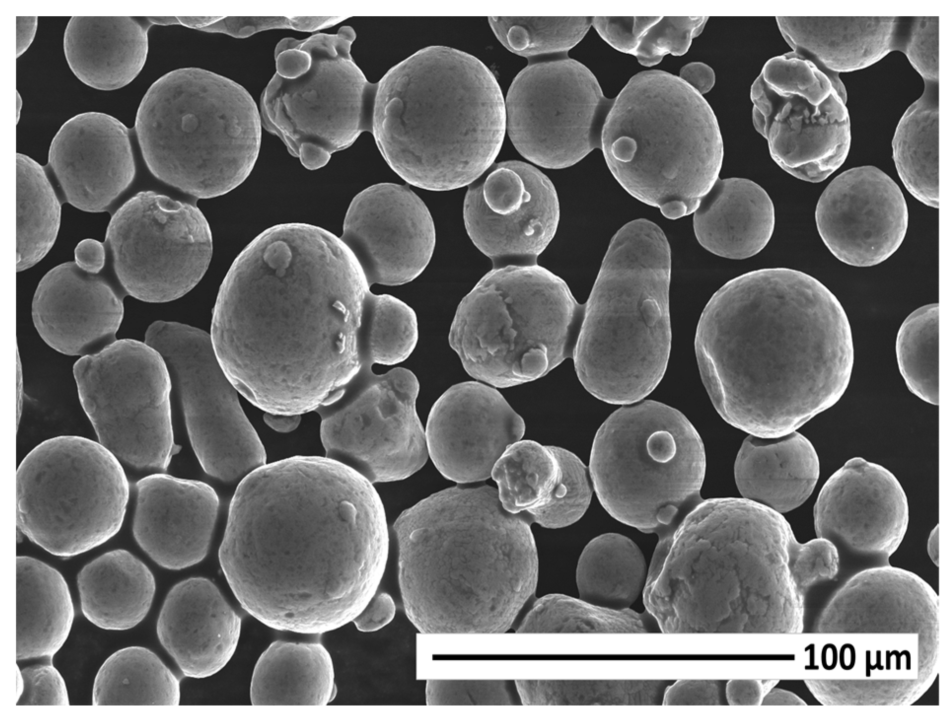
3.1. Characterisation of Powders and Determination of the Sinterability
3.2. Solid Loading Determination and Rheological Properties of the Feedstocks
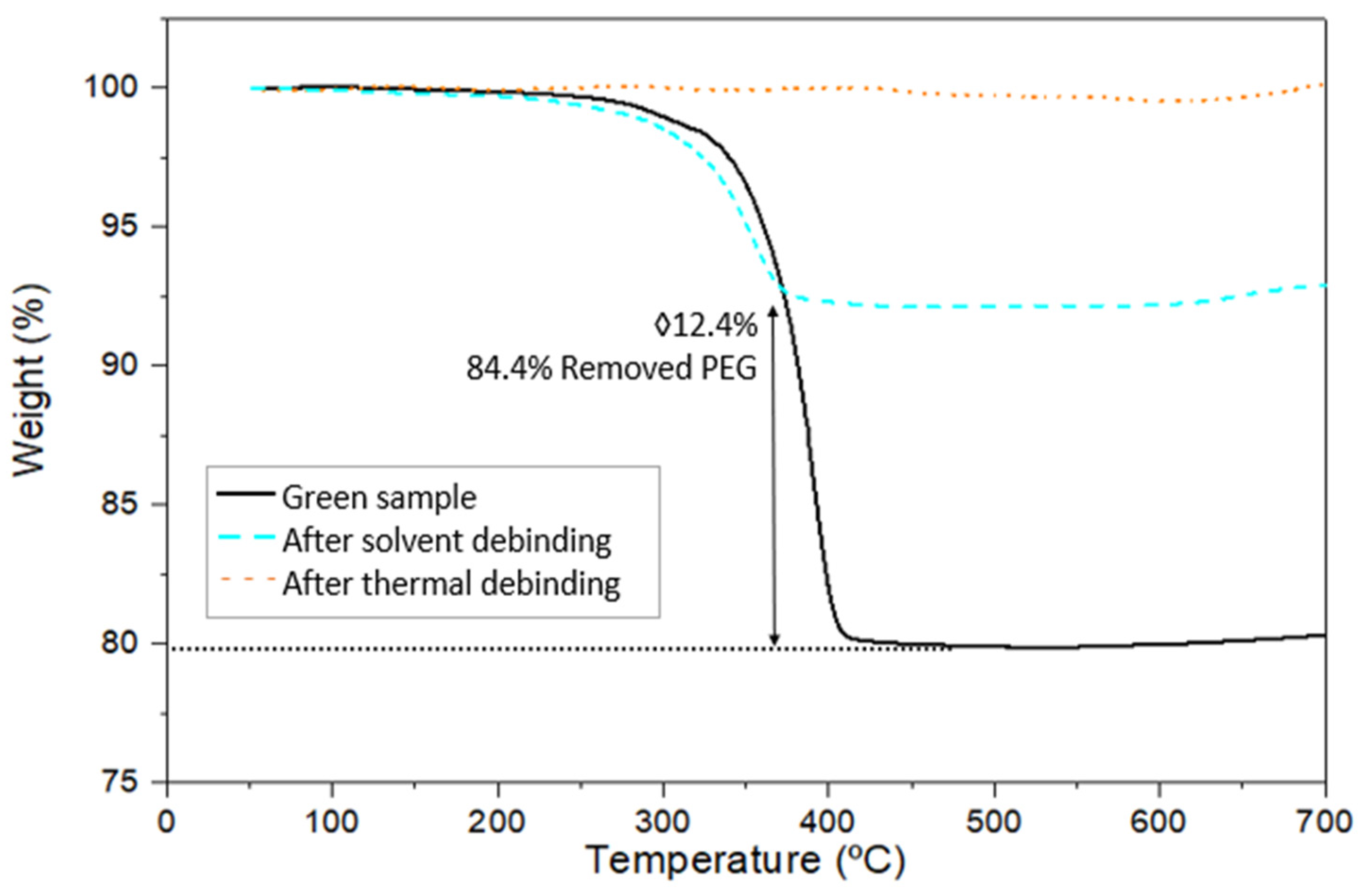
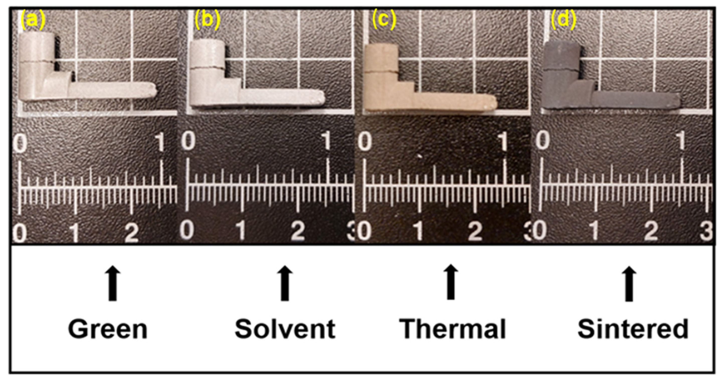
3.3. Processing of the Injected Samples: Debinding and Sintering
4. Conclusions
Author Contributions
Funding
Institutional Review Board Statement
Informed Consent Statement
Data Availability Statement
Conflicts of Interest
References
- Mondolfo, L. Aluminum Alloys: Structre & Properties; Butterworth Heinemann: Oxford, UK, 1976; ISBN 978-0-408-70932-3. [Google Scholar]
- Król, M.; Tański, T.; Snopiński, P.; Tomiczek, B. Structure and Properties of Aluminium–Magnesium Casting Alloys after Heat Treatment. J. Therm. Anal. Calorim. 2017, 127, 299–308. [Google Scholar] [CrossRef]
- Guo, X.; Tao, L.; Zhu, S.; Zong, S. Experimental Investigation of Mechanical Properties of Aluminum Alloy at High and Low Temperatures. J. Mater. Civ. Eng. 2020, 32, 06019016. [Google Scholar] [CrossRef]
- Graf, A. Aluminum Alloys for Lightweight Automotive Structures. In Materials, Design and Manufacturing for Lightweight Vehicles; Woodhead Publishing: Sawston, UK, 2020; ISBN 9780128187128. [Google Scholar]
- Wu, M.; Liu, Y.; Wang, T.; Yu, K. Deformation Behavior and Characteristics of Sintered Porous 2024 Aluminum Alloy Compressed in a Semisolid State. Mater. Sci. Eng. A 2016, 674, 144–150. [Google Scholar] [CrossRef]
- Zhao, N.; Ma, H.; Sun, Q.; Hu, Z.; Yan, Y.; Chen, T.; Hua, L. Microstructural Evolutions and Mechanical Properties of 6082 Aluminum Alloy Part Produced by a Solution-Forging Integrated Process. J. Mater. Process. Technol. 2022, 308, 117715. [Google Scholar] [CrossRef]
- Christy, J.V.; Arunachalam, R.; Mourad, A.H.I.; Krishnan, P.K.; Piya, S.; Al-Maharbi, M. Processing, Properties, and Microstructure of Recycled Aluminum Alloy Composites Produced Through an Optimized Stir and Squeeze Casting Processes. J. Manuf. Process. 2020, 59, 287–301. [Google Scholar] [CrossRef]
- Olakanmi, E.O.; Cochrane, R.F.; Dalgarno, K.W. A Review on Selective Laser Sintering/Melting (SLS/SLM) of Aluminium Alloy Powders: Processing, Microstructure, and Properties. Prog. Mater. Sci. 2015, 74, 401–477. [Google Scholar] [CrossRef]
- Agarwala, M.; Bourell, D.; Beaman, J.; Marcus, H.; Barlow, J. Direct Selective Laser Sintering of Metals. Rapid Prototyp. J. 1995, 1, 26–36. [Google Scholar] [CrossRef]
- Das, S.; Wohlert, M.; Beaman, J.J.; Bourell, D.L. Producing Metal Parts with Selective Laser Sintering/Hot Isostatic Pressing. JOM 1998, 50, 17–20. [Google Scholar] [CrossRef]
- Heaney, D.F. Powders for Metal Injection Molding (MIM). In Handbook of Metal Injection Molding; Woodhead Publishing: Sawston, UK, 2019; ISBN 9780081021521. [Google Scholar]
- Ghanmi, O.; Demers, V. Molding Properties of Titanium-Based Feedstock Used in Low-Pressure Powder Injection Molding. Powder Technol. 2021, 379, 515–525. [Google Scholar] [CrossRef]
- Dhore, V.G.; Rathod, W.S.; Patil, K.N. Investigation of Mechanical Properties of Carbon Nanotubes Reinforced Aluminium Composite by Metal Injection Molding. Mater. Today Proc. 2018, 5, 20690–20698. [Google Scholar] [CrossRef]
- Contreras, J.M.; Jiménez-Morales, A.; Torralba, J.M. Influence of the Morphology and Particle Size on the Processing of Bronze 90/10 Powders by Metal Injection Moulding (MIM). Mater. Sci. Forum 2007, 534–536, 365–368. [Google Scholar] [CrossRef]
- Abajo, C.; Jiménez-Morales, A.; Manuel Torralba, J. New Processing Route for ZrSiO4 by Powder Injection Moulding Using an Eco-Friendly Binder System. Bol. Soc. Esp. Ceram. Vidr. 2015, 54, 93–100. [Google Scholar] [CrossRef]
- Hidalgo, J.; Abajo, C.; Jiménez-Morales, A.; Torralba, J.M. Effect of a Binder System on the Low-Pressure Powder Injection Moulding of Water-Soluble Zircon Feedstocks. J. Eur. Ceram. Soc. 2013, 33, 3185–3194. [Google Scholar] [CrossRef]
- United Nations Sustainable Development Goals. Department of Economic and Social Affairs Sustainable Development. Available online: https://sdgs.un.org/goals (accessed on 28 November 2023).
- Cao, P.; Hayat, M.D. Potential Feedstock Compositions for Metal Injection Molding of Reactive Metals. In Feedstock Technology for Reactive Metal Injection Molding; Elsevier: Amsterdam, The Netherlands, 2020. [Google Scholar]
- Lin, D.; Sanetrnik, D.; Cho, H.; Chung, S.T.; Kwon, Y.S.; Kate, K.H.; Hausnerova, B.; Atre, S.V.; Park, S.J. Rheological and Thermal Debinding Properties of Blended Elemental Ti-6Al-4V Powder Injection Molding Feedstock. Powder Technol. 2017, 311, 357–363. [Google Scholar] [CrossRef]
- Romanov, G.N. Liquid-Phase Sintering of Aluminum-Based Powder Alloys. Russ. J. Non-Ferrous Met. 2010, 51, 347–351. [Google Scholar] [CrossRef]
- Tabares, E.; Kitzmantel, M.; Neubauer, E.; Jimenez-Morales, A.; Tsipas, S.A. Extrusion-Based Additive Manufacturing of Ti3SiC2 and Cr2AlC MAX Phases as Candidates for High Temperature Heat Exchangers. J. Eur. Ceram. Soc. 2022, 42, 841–849. [Google Scholar] [CrossRef]
- Singh, G.; Missiaen, J.M.; Bouvard, D.; Chaix, J.M. Copper Extrusion 3D Printing Using Metal Injection Moulding Feedstock: Analysis of Process Parameters for Green Density and Surface Roughness Optimization. Addit. Manuf. 2021, 38, 101778. [Google Scholar] [CrossRef]
- Mukund, B.N.; Hausnerova, B. Variation in Particle Size Fraction to Optimize Metal Injection Molding of Water Atomized 17–4PH Stainless Steel Feedstocks. Powder Technol. 2020, 368, 130–136. [Google Scholar] [CrossRef]
- Hidalgo, J.; Jiménez-Morales, A.; Torralba, J.M. Torque Rheology of Zircon Feedstocks for Powder Injection Moulding. J. Eur. Ceram. Soc. 2012, 32, 4063–4072. [Google Scholar] [CrossRef]
- Obse, L.A.S. Determination of the Melt Mass-Flow Rate (MFR) and Melt Volume-Flow Rate (MVR) of Thermoplastics 2012. Available online: https://www.une.org/encuentra-tu-norma/busca-tu-norma/norma?c=N0049710 (accessed on 18 December 2023).
- Olivier, D.; Aboubabky, A.; Antonia, J.M.; Manuel, T.J.; Thierry, B. Experimental and Numerical Analysis of Effects of Supercritical Carbon Dioxide Debinding on Inconel 718 MIM Components. Powder Technol. 2019, 355, 57–66. [Google Scholar] [CrossRef]
- Schaffer, G.B.; Hall, B.J.; Bonner, S.J.; Huo, S.H.; Sercombe, T.B. The Effect of the Atmosphere and the Role of Pore Filling on the Sintering of Aluminium. Acta Mater. 2006, 54, 131–138. [Google Scholar] [CrossRef]
- Wu, L.; Yu, Z.; Liu, C.; Ma, Y.; Huang, Y.; Wang, T.; Yang, L.; Yan, H.; Liu, W. Microstructure and Tensile Properties of Aluminum Powder Metallurgy Alloy Prepared by a Novel Low-Pressure Sintering. J. Mater. Res. Technol. 2021, 14, 1419–1429. [Google Scholar] [CrossRef]
- Sercombe, T.B.; Schaffer, G.B. The Effect of Trace Elements on the Sintering of Al-Cu Alloys. Acta Mater. 1999, 47, 689–697. [Google Scholar] [CrossRef]
- Liu, Z.Y.; Sercombe, T.B.; Schaffer, G.B. Metal Injection Moulding of Aluminium Alloy 6061 with Tin. Powder Metall. 2008, 51, 78–83. [Google Scholar] [CrossRef]
- Min, K.H.; Kang, S.P.; Lee, B.H.; Lee, J.K.; Kim, Y. Do Liquid Phase Sintering of the Commercial 2xxx Series Al Blended Powder. J. Alloys Compd. 2006, 419, 290–293. [Google Scholar] [CrossRef]
- Du, X.; Liu, R.; Xiong, X.; Liu, H. Effects of Sintering Time on the Microstructure and Properties of an Al-Cu-Mg Alloy. J. Mater. Res. Technol. 2020, 9, 9657–9666. [Google Scholar] [CrossRef]
- Liu, J.; Lal, A.; German, R.M. Densification and Shape Retention in Supersolidus Liquid Phase Sintering. Acta Mater. 1999, 47, 4615–4626. [Google Scholar] [CrossRef]
- German, R.M. Supersolidus Liquid-Phase Sintering of Prealloyed Powders. Metall. Mater. Trans. A Phys. Metall. Mater. Sci. 1997, 28, 1553–1567. [Google Scholar] [CrossRef]
- Li, T. Powder Injection Molding of Metallic Parts and Structures. In Encyclopedia of Materials: Metals and Alloys; Elsevier: Amsterdam, The Netherlands, 2021; ISBN 9780128197264. [Google Scholar]
- Md Ani, S.; Muchtar, A.; Muhamad, N.; Ghani, J.A. Fabrication of Zirconia-Toughened Alumina Parts by Powder Injection Molding Process: Optimized Processing Parameters. Ceram. Int. 2014, 40, 273–280. [Google Scholar] [CrossRef]
- Barreiros, F.M.; Vieira, M.T. PIM of Non-Conventional Particles. Ceram. Int. 2006, 32, 297–302. [Google Scholar] [CrossRef]
- Tabares, E.; Cifuentes, S.C.; Jiménez-Morales, A.; Tsipas, S.A. Injection Moulding of Porous MAX Phase Ti3SiC2 without Using Space-Holder. Powder Technol. 2021, 380, 96–105. [Google Scholar] [CrossRef]
- Atre, S.V.; Weaver, T.J.; German, R.M. Injection Molding of Metals and Ceramics; In Proceedings of the SAE Technical Papers; SAE International, Princeton, NJ, USA, 1998. [CrossRef]
- Hidalgo, J.; Jiménez-Morales, A.; Barriere, T.; Gelin, J.C.; Torralba, J.M. Capillary Rheology Studies of INVAR 36 Feedstocks for Powder Injection Moulding. Powder Technol. 2015, 273, 1–7. [Google Scholar] [CrossRef]
- Hidalgo, J.; Jiménez-Morales, A.; Torralba, J.M. Thermal Stability and Degradation Kinetics of Feedstocks for Powder Injection Moulding-A New Way to Determine Optimal Solid Loading? Polym. Degrad. Stab. 2013, 98, 1188–1195. [Google Scholar] [CrossRef]


| Element | Si | Fe | Cu | Mn | Mg | Cr | Zn | Ti | Al |
|---|---|---|---|---|---|---|---|---|---|
| wt.% | 0.10 | 0.13 | 4.67 | 0.55 | 1.73 | <0.01 | 0.11 | <0.01 | balance |
| Binder | PEG | CAB |
|---|---|---|
| Vol.% | 70 | 30 |
| Molecular weight (g/mol) | 4000 | 30,000 |
| 20,000 | ||
| Supplier | Sigma-Aldrich | Eastman |
| D10 (µm) | D50 (µm) | D90 (µm) |
|---|---|---|
| 28.89 ± 0.01 | 49.85 ± 0.02 | 82.88 ± 0.03 |
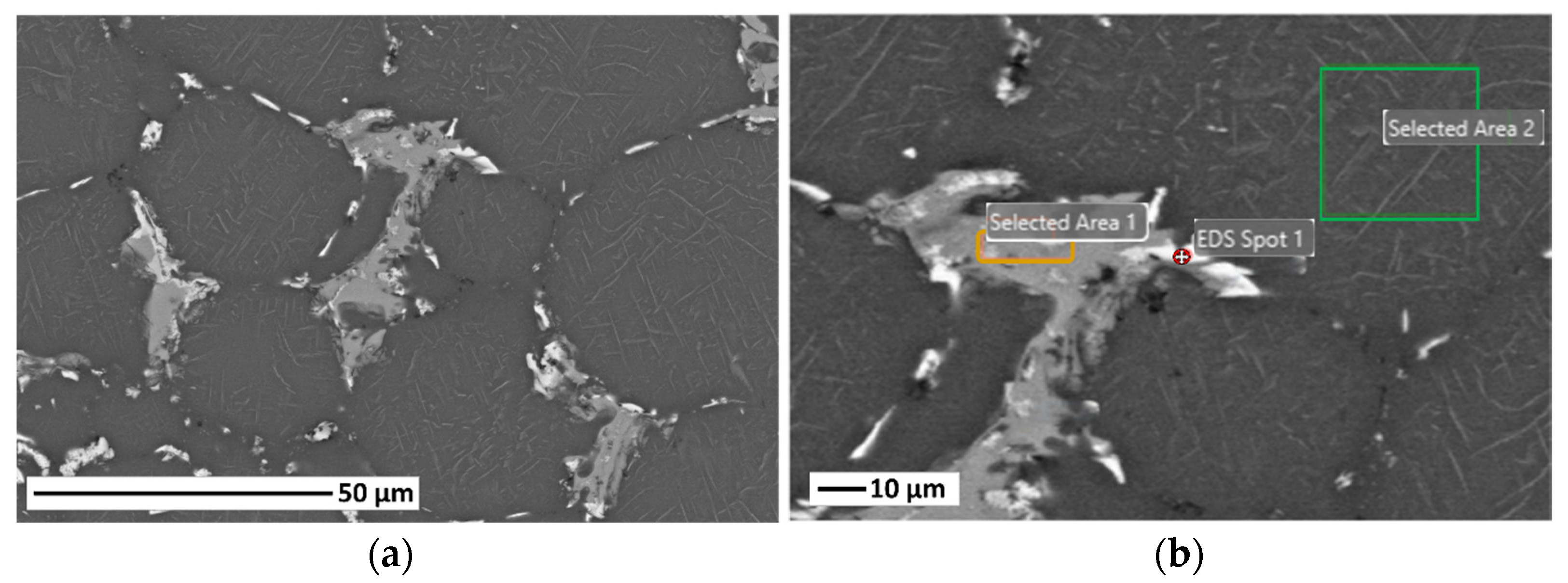
| Element | Weight % | Error % |
|---|---|---|
| EDS Spot 1 | ||
| Mg | 1.6 | 11.4 |
| Al | 60.3 | 7.2 |
| Mn | 1.2 | 15.5 |
| Fe | 1.2 | 16.5 |
| Cu | 35.6 | 3.0 |
| Selected Area 1 | ||
| Al | 71.8 | 6.0 |
| Mn | 7.5 | 4.3 |
| Fe | 9.4 | 4.1 |
| Cu | 11.3 | 5.0 |
| Selected Area 2 | ||
| Mg | 2.0 | 6.8 |
| Al | 93.9 | 4.0 |
| Mn | 0.6 | 25.6 |
| Cu | 3.5 | 9.0 |
| Feedstock | Green Parts | After Sintering | ||
|---|---|---|---|---|
| Al2024 61 vol.% | ρrel (%) | Closed Porosity (%) | ρrel (%) | Closed Porosity (%) |
| 79.1 ± 1.5 | 20.9 ± 1.5 | 83.7 ± 1.7 | 16.3 ± 1.7 | |
Disclaimer/Publisher’s Note: The statements, opinions and data contained in all publications are solely those of the individual author(s) and contributor(s) and not of MDPI and/or the editor(s). MDPI and/or the editor(s) disclaim responsibility for any injury to people or property resulting from any ideas, methods, instructions or products referred to in the content. |
© 2024 by the authors. Licensee MDPI, Basel, Switzerland. This article is an open access article distributed under the terms and conditions of the Creative Commons Attribution (CC BY) license (https://creativecommons.org/licenses/by/4.0/).
Share and Cite
Aguilar-García, J.L.; Lorenzo, E.T.; Jimenez-Morales, A.; Ruíz-Navas, E.M. Design of Sustainable Aluminium-Based Feedstocks for Composite Extrusion Modelling (CEM). Materials 2024, 17, 1093. https://doi.org/10.3390/ma17051093
Aguilar-García JL, Lorenzo ET, Jimenez-Morales A, Ruíz-Navas EM. Design of Sustainable Aluminium-Based Feedstocks for Composite Extrusion Modelling (CEM). Materials. 2024; 17(5):1093. https://doi.org/10.3390/ma17051093
Chicago/Turabian StyleAguilar-García, José L., Eduardo Tabares Lorenzo, Antonia Jimenez-Morales, and Elisa M. Ruíz-Navas. 2024. "Design of Sustainable Aluminium-Based Feedstocks for Composite Extrusion Modelling (CEM)" Materials 17, no. 5: 1093. https://doi.org/10.3390/ma17051093