
Diagnostics of Large-Panel Buildings—An Attempt to Reduce the Number of Destructive Tests

Abstract
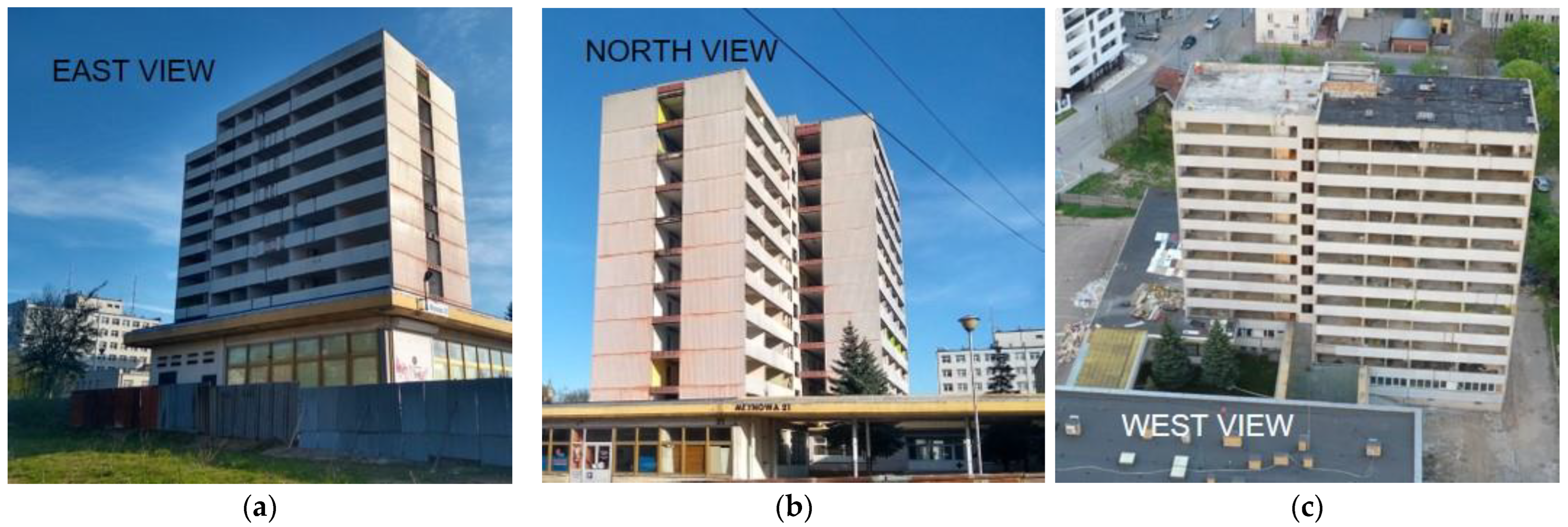
:1. Introduction
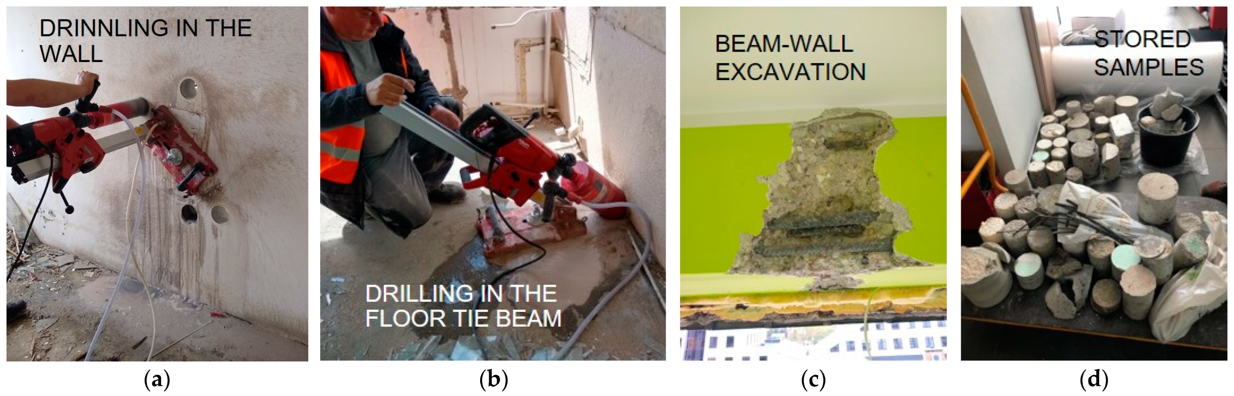
2. Structural Diagnostics—Own Research
2.1. Methods of Assesing the Quality and Strength of Concrete
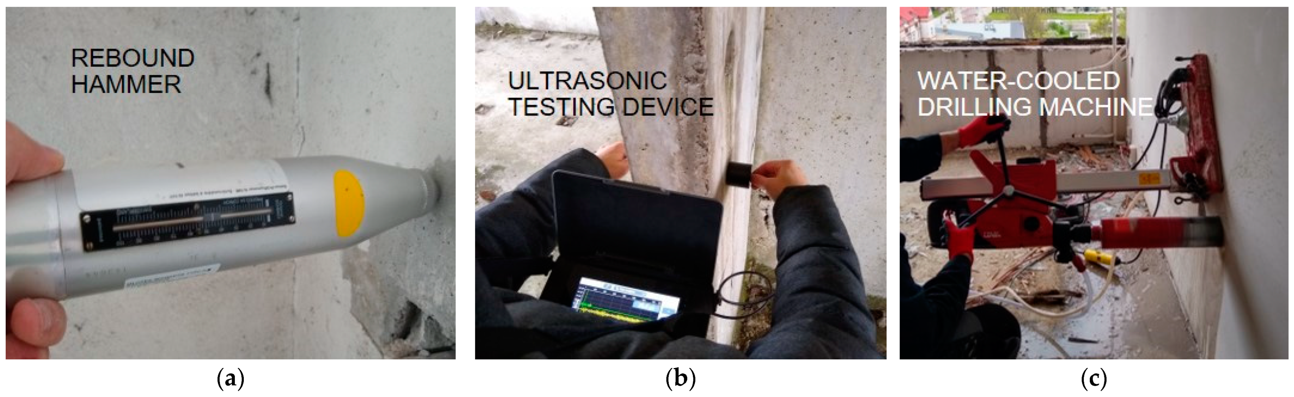
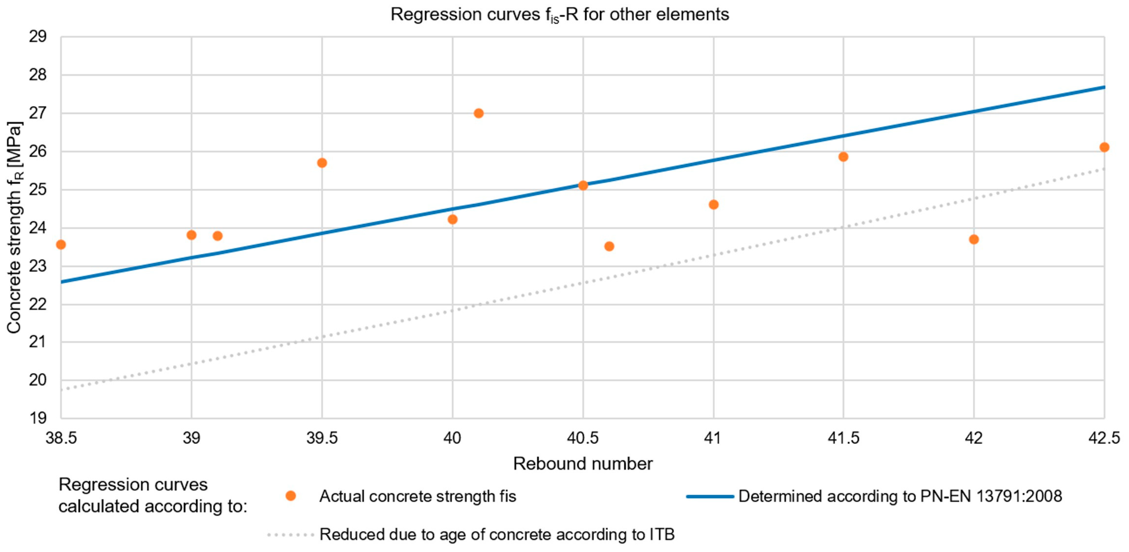
2.1.1. Concrete Compressive Strength Testing by Sclerometric Method
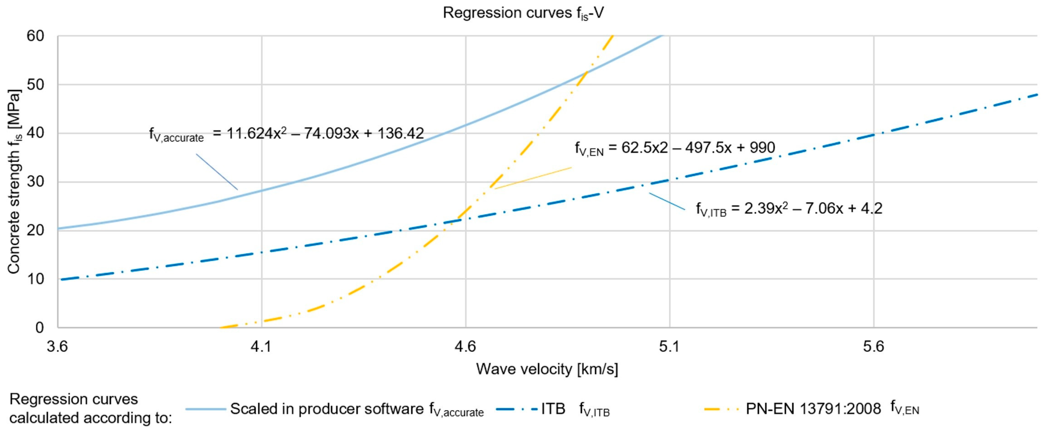
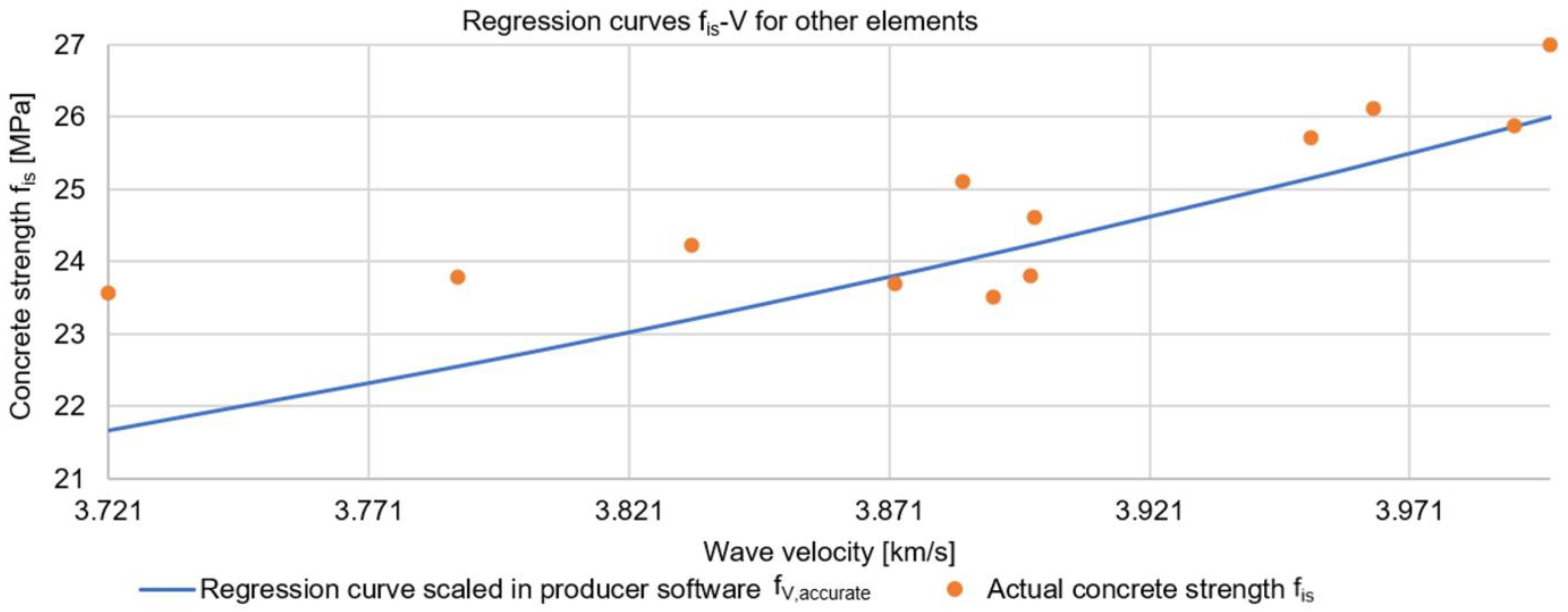
2.1.2. Concrete Compressive Strength Testing by Ultrasonic Method
2.1.3. Testing the Quality/Homogeneity of Concrete Using Sclerometric and Ultrasonic Methods
2.2. Methods of Assessing the Condition and Strength of Steel
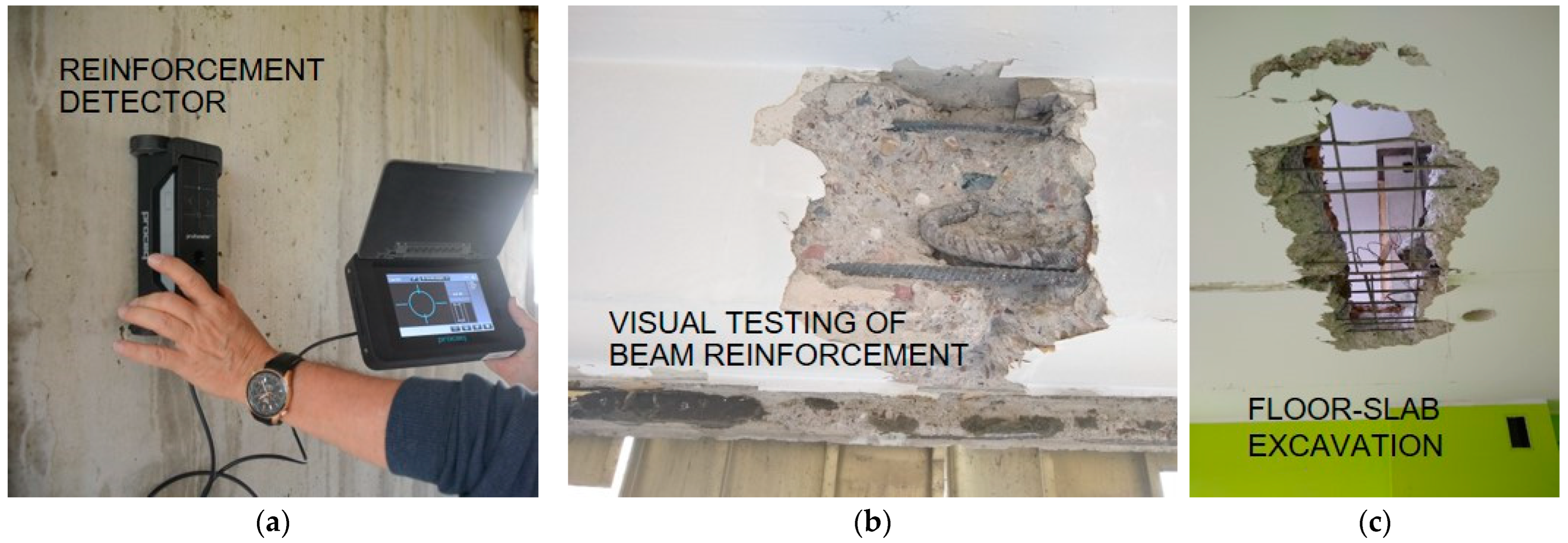
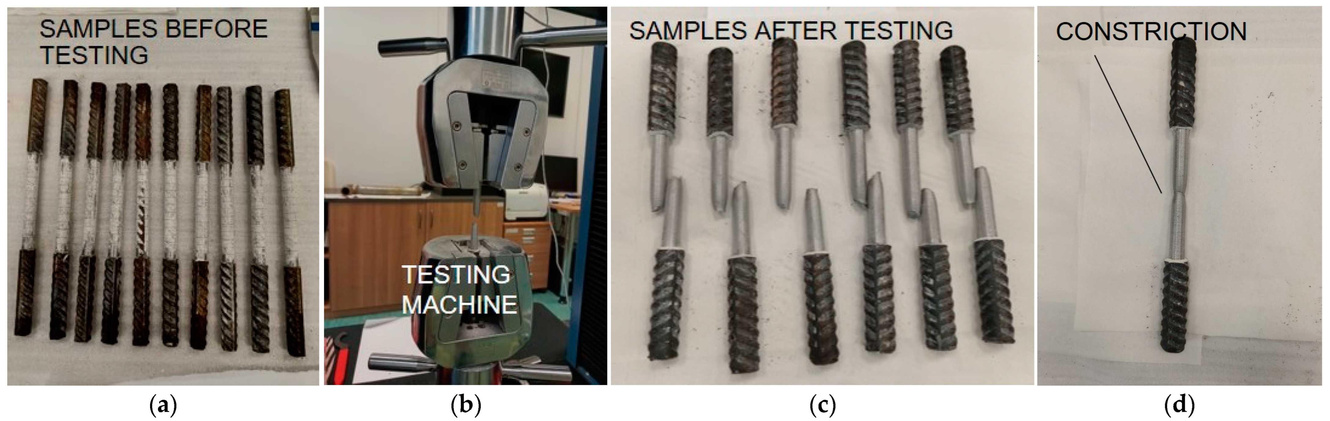
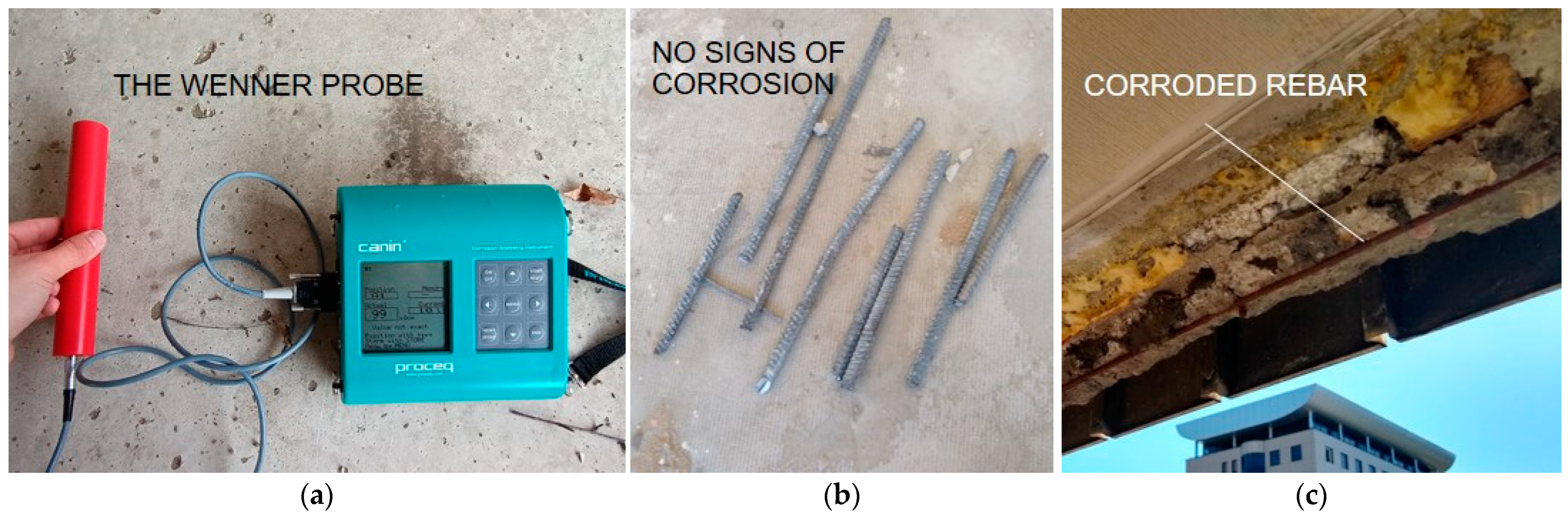
2.2.1. Testing the Quality of Reinforcement Works and Strength of Bars
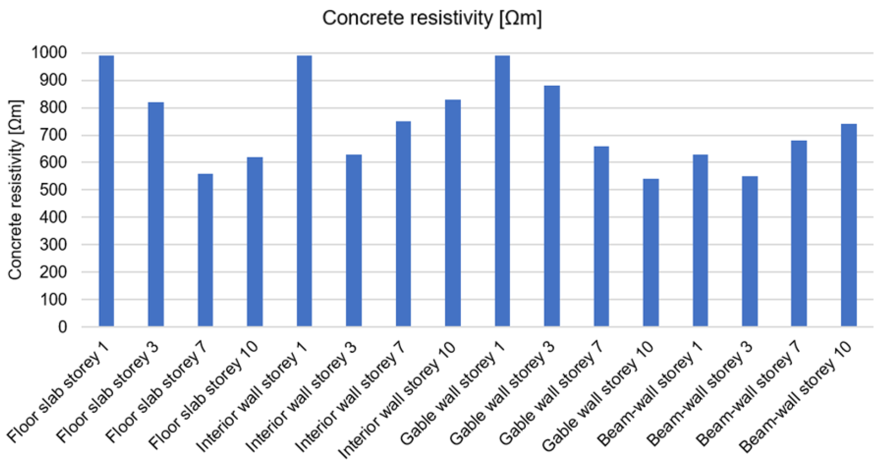
2.2.2. Concrete Resistivity Testing—Estimating the Risk of Reinforcement Corrosion Processes
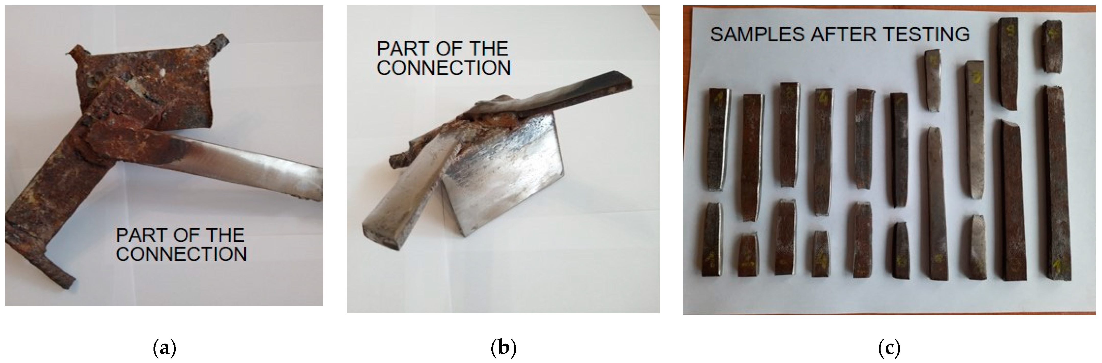
2.2.3. Testing the Strength of Steel Connections
3. Discussion—Practical Aspects of Diagnostics
4. Conclusions
- Problems associated with determining the location and number of survey points. The authors recommend starting the survey by performing a visual inspection to assess the condition of the object and identify degraded areas. Then, carry out non-destructive tests to provide a basis for selecting sites for taking cores in areas of questionable quality.
- Lack of access to archival documentation of the investigated building. This makes it difficult to identify the original structural assumptions and solutions. In the absence of such documentation, it is recommended to make an initial assumption that all main structural elements were made of the same class of concrete.
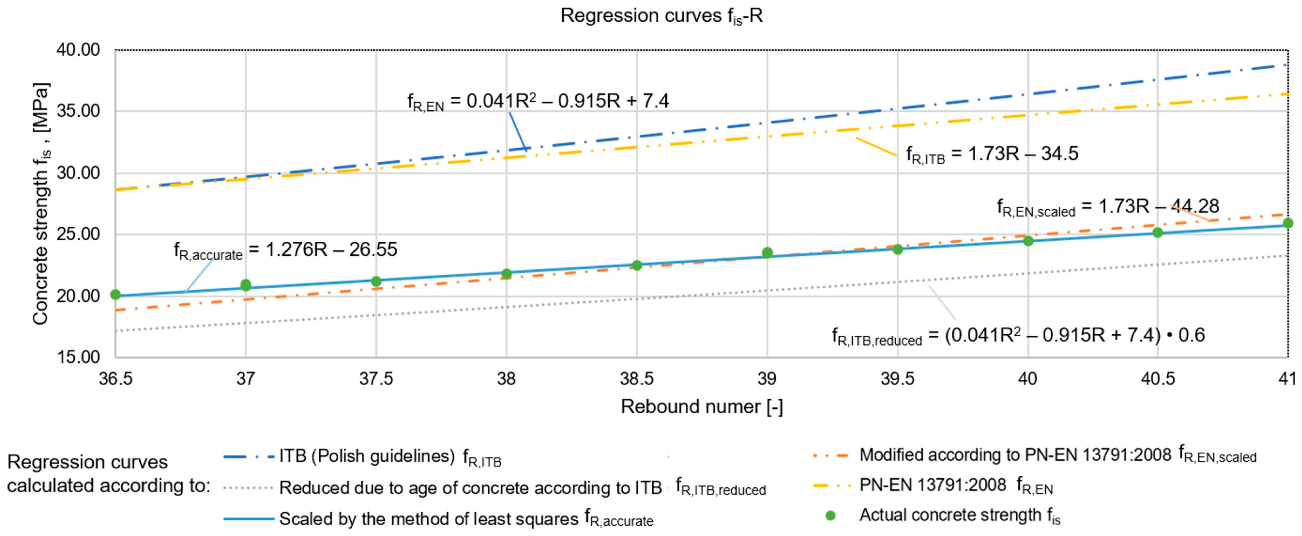
- Uncertainty of results obtained using non-destructive methods. The results obtained using these methods are influenced by many factors, including moisture content, temperature, carbonisation processes, reinforcement, cracking and voids. In order to minimise the risk of obtaining an incorrect result, it is recommended to carry out comparative tests with two non-destructive methods. The results need to be confirmed by data obtained from destructive testing. These data should form the basis for finding empirical relationships between the destructive method and non-destructive methods: ultrasonic and sclerometric. When estimating the strength of concrete in subsequent structural elements already without confirming the results with cores, measurement by two non-destructive methods increases confidence in the data obtained. It also makes it possible to locate questionable areas in the event of differing values being obtained at the measuring point under examination, which provides an indication of the need for further destructive testing.
- Lack of possibility for destructive testing. In the absence of core drilling, estimating the compressive strength of concrete based solely on non-destructive methods is subject to a high risk of error. However, based on professional experience, the authors have sometimes found themselves in situations in which they have been forced to suggest only the results obtained using non-destructive methods. At that time, the guiding principle was that it was better to have estimates as a basis for any analysis than to be based only on visual assessment.
- The assessment of the compressive strength of concrete, when core drilling is not possible, should be based on the use of the sclerometric method and regression curves that take into account the age of the concrete. The ultrasonic method is then proposed to assess the quality of the concrete and locate areas of questionable quality.
- Determination of the cover thickness and spacing of the reinforcement can be successfully carried out using the electromagnetic method. However, the sensitive data are the rebar diameters, as it is necessary to take into account the measuring accuracy of the instrument and type of rebar (ribbed/smooth).
- In most cases, it may not be necessary to assess the tensile strength of the reinforcing steel. However, if it is required to assess the strength parameters of the steel, it is recommended to identify the area where the rebars run and then to drill a core. This core can be used in two ways: first to determine the strength of the concrete and then, after breaking, to obtain a sample of the reinforcement. The rebar can be visually examined to assess corrosion processes and then be tested in a machine. According to the authors’ numerous experiences, the effect of the reinforcement placed transverse to the drill axis on the compressive strength of the concrete can be neglected in most cases. This reduces the need for performing additional excavations.
- A concrete resistivity test can be helpful to assess whether the concrete cover is conducive to corrosion processes of the reinforcing steel. This test is recommended to be carried out in the area of planned excavations or drillings in order to be able to confirm the results.
- The tensile strength of steel connection plates can be successfully determined by correlation with its hardness, using ultrasonic hardness testers. Destructive tests can be reduced to the minimum number necessary to confirm the parameters obtained using non-destructive methods.
- Lack of equipment to identify degradation of steel joints without performing excavations.
- Lack of research methodologies related to the assessment of the degradation status of facade layer connections in gable walls and beam-walls in modernised buildings.
Author Contributions
Funding
Institutional Review Board Statement
Informed Consent Statement
Data Availability Statement
Conflicts of Interest
References
- Folic, R.; Laban, M.; Milanko, V. Reliability and Sustainability Analysis of Large Panel Residential Buildings in Sofia, Skopje and Novi Sad. Facta Univ.-Ser. Archit. Civ. Eng. 2011, 9, 161–176. [Google Scholar] [CrossRef]
- Radziejowska, A.; Sobotka, A. Assessment of Large-Panel Prefabricated Buildings in the Social Aspect of Sustainable Construction|Ocena Budynków z Wielkiej Płyty w Aspekcie Socjalnym Zrównoważonego Budownictwa. Arch. Civ. Eng. 2021, 67, 93–108. [Google Scholar]
- Rák, O.; Borsos, Á.; Iványi, P. Examination of Large-Panel Building Apartments Renovation. Pollack Period. 2021, 16, 143–149. [Google Scholar] [CrossRef]
- Onyszkiewicz, J.; Sadowski, K. Proposals for the Revitalization of Prefabricated Building Facades in Terms of the Principles of Sustainable Development and Social Participation. J. Build. Eng. 2022, 46, 103713. [Google Scholar] [CrossRef]
- Kadela, M.; Cincio, A.; Fedorowicz, J.; Gerylo, R. Attempt at Numerical Representation of Gas Explosion in a Large Panel Building. In Proceedings of the IOP Conference Series: Materials Science and Engineering, Prague, Czech Republic, 17–21 June 2019; Volume 603. [Google Scholar] [CrossRef]
- Hryhorovskyi, P.; Osadcha, I.; Jurelionis, A.; Basanskyi, V.; Hryhorovskyi, A. A BIM-Based Method for Structural Stability Assessment and Emergency Repairs of Large-Panel Buildings Damaged by Military Actions and Explosions: Evidence from Ukraine. Buildings 2022, 12, 1817. [Google Scholar] [CrossRef]
- Guri, M.; Brzev, S.; Lluka, D. Performance of Prefabricated Large Panel Reinforced Concrete Buildings in the November 2019 Albania Earthquake. J. Earthq. Eng. 2022, 26, 5799–5825. [Google Scholar] [CrossRef]
- Jędrzejczyk, A.; Byrdy, A.; Firek, K.; Rusek, J. Partial Least Squares Regression Approach in the Analysis of Damage Intensity Changes to Prefabricated RC Buildings during the Long Term of Mining Activity. Appl. Sci. 2022, 12, 467. [Google Scholar] [CrossRef]
- Ghazi Wakili, K.; Dworatzyk, C.; Sanner, M.; Sengespeick, A.; Paronen, M.; Stahl, T. Energy Efficient Retrofit of a Prefabricated Concrete Panel Building (Plattenbau) in Berlin by Applying an Aerogel Based Rendering to Its Façades. Energy Build. 2018, 165, 293–300. [Google Scholar] [CrossRef]
- Ilomets, S.; Kalamees, T. Evaluation of the Criticality of Thermal Bridges. J. Build. Pathol. Rehabil. 2016, 1, 11. [Google Scholar] [CrossRef]
- Dzierżewicz, Z.; Starosolski, W. Large Panel Systems in Poland in Years 1970–1985; Oficyna A Wolters Kluwer Business: Warsaw, Poland, 2010. (In Polish) [Google Scholar]
- Harish Kumar, K.; Veerendra Babu, N.; Lingeshwaran, N. A Study on Repair of Concrete Structure Using Non Destructive Tests. Mater. Today Proc. 2021, 47, 5439–5446. [Google Scholar] [CrossRef]
- Tofiluk, A.; Knyziak, P.; Krentowski, J. Revitalization of Twentieth-Century Prefabricated Housing Estates as Interdisciplinary Issue. In Proceedings of the IOP Conference Series: Materials Science and Engineering, Prague, Czech Republic, 18–22 June 2018; Volume 471. [Google Scholar] [CrossRef]
- Ligęza, W. Renovation of Large-Panel Buildings in Context of Urban Renewal. Civ. Environ. Eng. Rep. 2015, 17, 83–95. [Google Scholar] [CrossRef]
- Krentowski, J.R.; Knyziak, P.; Mackiewicz, M. Durability of Interlayer Connections in External Walls in Precast Residential Buildings. Eng. Fail. Anal. 2021, 121, 105059. [Google Scholar] [CrossRef]
- Kałuża, M.; Ajdukiewicz, A. Comparison of Behaviour of Concrete Beams with Passive and Active Strengthening by Means of CFRP Strips. Archit. Civ. Eng. Environ. 2008, 1, 51–64. [Google Scholar]
- Kotynia, R.; Oller, E.; Marí, A.; Kaszubska, M. Efficiency of Shear Strengthening of RC Beams with Externally Bonded FRP Materials—State-of-the-Art in the Experimental Tests. Compos. Struct. 2021, 267, 113891. [Google Scholar] [CrossRef]
- Cai, G.; Zhao, J. Application of Sulphoaluminate Cement to Repair Deteriorated Concrete Members in Chloride Ion Rich Environment-A Basic Experimental Investigation of Durability Properties. KSCE J. Civ. Eng. 2016, 20, 2832–2841. [Google Scholar] [CrossRef]
- Czarnecki, S. Ultrasonic Evaluation of the Pull-Off Adhesion between Added Repair Layer and a Concrete Substrate. IOP Conf. Ser. Mater. Sci. Eng. 2017, 245, 032037. [Google Scholar] [CrossRef]
- Varzaneh, A.S.; Naderi, M. Determination of Shrinkage, Tensile and Compressive Strength of Repair Mortars and Their Adhesion on the Concrete Substrate Using “Twist-off” and “Pull-off” Methods. Iran. J. Sci. Technol. Trans. Civ. Eng. 2021, 45, 2377–2395. [Google Scholar] [CrossRef]
- Liu, Y.; Wang, M.; Tian, W.; Qi, B.; Lei, Z.; Wang, W. Ohmic Heating Curing of Carbon Fiber/Carbon Nanofiber Synergistically Strengthening Cement-Based Composites as Repair/Reinforcement Materials Used in Ultra-Low Temperature Environment. Compos. Part A Appl. Sci. Manuf. 2019, 125, 105570. [Google Scholar] [CrossRef]
- Brzozowski, P.; Horszczaruk, E. Influence of Surface Preparation on Adhesion of Underwater Repair Concretes under Hydrostatic Pressure. Constr. Build. Mater. 2021, 310, 125153. [Google Scholar] [CrossRef]
- Gupta, S.; Pang, S.D.; Kua, H.W. Autonomous Healing in Concrete by Bio-Based Healing Agents—A Review. Constr. Build. Mater. 2017, 146, 419–428. [Google Scholar] [CrossRef]
- Jiang, L.; Han, Q.; Wang, W.; Zhang, Y.; Lu, W.; Li, Z. A Sugar-Coated Microbial Agent for Self-Healing Cracks in Concrete. J. Build. Eng. 2023, 66, 105890. [Google Scholar] [CrossRef]
- Forcellini, D.; Kalfas, K.N. Inter-Story Seismic Isolation for High-Rise Buildings. Eng. Struct. 2023, 275, 115175. [Google Scholar] [CrossRef]
- Amit, R.D.; Gajjar, R. Structural Control System for Mid-Rise Building. Int. J. Adv. Eng. Technol. 2012, 3, 30–33. [Google Scholar]
- Knyziak, P. The Impact of Construction Quality on the Safety of Prefabricated Multi-Family Dwellings. Eng. Fail. Anal. 2019, 100, 37–48. [Google Scholar] [CrossRef]
- Knyziak, P.; Bieranowski, P.; Krentowski, J.R. Impact of Corrosion Processes in the Basement Level on the Durability of the Construction of Large-Panel Buildings. In Proceedings of the MATEC Web of Conferences, Warsaw, Poland, 21–25 August 2017; Volume 117. [Google Scholar] [CrossRef]
- Mackiewicz, M.; Krentowski, J.R.; Knyziak, P.; Wardach, M. Consequences of Excessive Deformation of Structural Elements in Precast Buildings. Eng. Fail. Anal. 2022, 137, 106261. [Google Scholar] [CrossRef]
- Baszeń, M.; Miedziałowski, C. An Environmental Impact on the Condition of an Unfinished Building in the OWT Technology. In Proceedings of the E3S Web of Conferences, Polańczyk, Poland, 19–23 June 2018; Volume 49. [Google Scholar] [CrossRef]
- Knyziak, P. The Quality and Reliability in the Structural Design, Production, Execution and Maintenance of the Precast Residential Buildings in Poland in the Past and Now. Key Eng. Mater. 2016, 691, 420–431. [Google Scholar] [CrossRef]
- Szulc, J.; Piekarczuk, A. Diagnostics and Technical Condition Assessment of Large-Panel Residential Buildings in Poland. J. Build. Eng. 2022, 50, 104144. [Google Scholar] [CrossRef]
- Górski, W. Problems of Early Large Panel Structures in Poland. Acta Sci. Pol.–Archit. Bud. 2001, 20, 45–53. [Google Scholar] [CrossRef]
- Kalamees, T.; Õiger, K.; Kõiv, T.; Liias, R.; Kallavus, U.; Mikli, L.; Lehtla, A.; Kodi, G.; Arumägi, E. Technical Condition of Prefabricated Concrete Large Panel Apartment Buildings in Estonia. In Proceedings of the 12DBMC–International Conference on Durability of Building Materials and Components, Porto, Portugal, 12–15 April 2011; pp. 1–9. [Google Scholar]
- Wardach, M. Assessment of the Degradation State of Joints in Large-Panel Buildings. Eng. Fail. Anal. 2023, 145, 107020. [Google Scholar] [CrossRef]
- Wardach, M. Assessing the Technical Condition of Unfinished or Temporarily Out-of-Service Large-Panel Buildings. Mater. Bud. 2022, 1, 108–111. [Google Scholar] [CrossRef]
- Wardach, M.; Krentowski, J.R.; Knyziak, P. Degradation Analyses of Systemic Large-Panel Buildings Using Comparative Testing during Demolition. Materials 2022, 15, 3770. [Google Scholar] [CrossRef] [PubMed]
- Wardach, M.; Krentowski, J.R.; Mackiewicz, M. Evaluation of Precast Beam Deflections Resulting in Cracks in Curtain Walls. Eng. Fail. Anal. 2022, 140, 106568. [Google Scholar] [CrossRef]
- Wardach, M.; Pawłowicz, J.A.; Kosior-Kazberuk, M.; Krentowski, J.R. The Diagnostics of the Condition and Management of Large-Panel Buildings Using Point Clouds and Building Information Modelling (BIM). Buildings 2023, 13, 2089. [Google Scholar] [CrossRef]
- Abdallah, W.; Sbartaï, Z.-M.; Saliba, J.; Elachachi, S.M.; Hage Chehade, F.; Sadek, M. Assessment of the Reliability of Concrete Evaluation by Multi-Physical Inversion of NDT Measurements—A Probabilistic Approach. Constr. Build. Mater. 2021, 300, 124371. [Google Scholar] [CrossRef]
- Kouddane, B.; Sbartaï, Z.M.; Alwash, M.; Ali-Benyahia, K.; Elachachi, S.M.; Lamdouar, N.; Kenai, S. Assessment of Concrete Strength Using the Combination of NDT—Review and Performance Analysis. Appl. Sci. 2022, 12, 12190. [Google Scholar] [CrossRef]
- Pallarés, F.J.; Betti, M.; Bartoli, G.; Pallarés, L. Structural Health Monitoring (SHM) and Nondestructive Testing (NDT) of Slender Masonry Structures: A Practical Review. Constr. Build. Mater. 2021, 297, 123768. [Google Scholar] [CrossRef]
- Yuva, Y. Low-Strength Concrete Properties in Existing Structures Using NDT and Core Test Results. J. Build. Eng. 2023, 76, 107281. [Google Scholar] [CrossRef]
- Dey, A.; Miyani, G.; Debroy, S.; Sil, A. In-Situ NDT Investigation to Estimate Degraded Quality of Concrete on Existing Structure Considering Time-Variant Uncertainties. J. Build. Eng. 2020, 27, 101001. [Google Scholar] [CrossRef]
- Kazemi, M.; Madandoust, R.; de Brito, J. Compressive Strength Assessment of Recycled Aggregate Concrete Using Schmidt Rebound Hammer and Core Testing. Constr. Build. Mater. 2019, 224, 630–638. [Google Scholar] [CrossRef]
- Stawiski, B.; Kania, T. Tests of Concrete Strength across the Thickness of Industrial Floor Using the Ultrasonic Method with Exponential Spot Heads. Materials 2020, 13, 2118. [Google Scholar] [CrossRef]
- Bacharz, K.; Raczkiewicz, W.; Bacharz, M.; Grzmil, W. Manufacturing Errors of Concrete Cover as a Reason of Reinforcement Corrosion in a Precast Element—Case Study. Coatings 2019, 9, 702. [Google Scholar] [CrossRef]
- Park, J.Y.; Yoon, Y.G.; Oh, T.K. Prediction of Concrete Strength with P-, S-, R-Wave Velocities by Support Vector Machine (SVM) and Artificial Neural Network (ANN). Appl. Sci. 2019, 9, 4053. [Google Scholar] [CrossRef]
- Kovler, K.; Wang, F.; Muravin, B. Testing of Concrete by Rebound Method: Leeb versus Schmidt Hammers. Mater. Struct. 2018, 51, 138. [Google Scholar] [CrossRef]
- Maj, M.; Ubysz, A.; Hammadeh, H.; Askifi, F. Non-Destructive Testing of Technical Conditions of RC Industrial Tall Chimneys Subjected to High Temperature. Materials 2019, 12, 2027. [Google Scholar] [CrossRef] [PubMed]
- Golewski, G.L. Evaluation of Fracture Processes under Shear with the Use of DIC Technique in Fly Ash Concrete and Accurate Measurement of Crack Path Lengths with the Use of a New Crack Tip Tracking Method. Measurement 2021, 181, 109632. [Google Scholar] [CrossRef]
- Golewski, G.L. Measurement of Fracture Mechanics Parameters of Concrete Containing Fly Ash Thanks to Use of Digital Image Correlation (DIC) Method. Measurement 2019, 135, 96–105. [Google Scholar] [CrossRef]
- Meyer, D.M.; Combrinck, R. Utilising MicroCT Scanning Technology as a Method for Testing and Analysing Plastic Shrinkage Cracks in Concrete. Constr. Build. Mater. 2022, 317, 125895. [Google Scholar] [CrossRef]
- EN 13791:2019-12; Assessment of In-Situ Compressive Strength in Structures and Precast Concrete Components. PKN: Warsaw, Poland, 2019.
- EN 13791:2008; Assessment of In-Situ Compressive Strength in Structures and Precast Concrete Components. PKN: Warsaw, Poland, 2008.
- Runkiewicz, L.; Sieczkowski, J. Ocena Wytrzymałości Betonu w Konstrukcjach Na Podstawie Badań Sklerometrycznych; Instytut Techniki Budowlanej: Warsaw, Poland, 2022. (In Polish) [Google Scholar]
- Runkiewicz, L.; Brunarski, L. Instrukcja Stosowania Młotków Schmidta Do Nieniszczącej Kontroli Jakości Betonu w Konstrukcji. Instrukcja Nr 210; Instytut Techniki Budowlanej: Warsaw, Poland, 1977. (In Polsih) [Google Scholar]
- Brunarski, L.; Runkiewicz, L. Instrukcja Stosowania Metody Ultradźwiękowej Do Nieniszczącej Kontroli Jakości Betonu w Konstrukcji; Instytut Techniki Budowlanej: Warsaw, Poland, 1977. (In Polish) [Google Scholar]
- Proceq, S.A. Profometer. Operating Instructions; Proceq SA: Schwerzenbach, Switzerland, 2014. [Google Scholar]
- Dermawan, A.S.; Dewi, S.M.; Wisnumurti; Wibowo, A. Performance Evaluation and Crack Repair in Building Infrastructure. IOP Conf. Ser. Earth Env. Sci. 2019, 328, 012007. [Google Scholar] [CrossRef]
- PN-H-93215:1969; Walcówka Pręty Stalowe Do Zbrojenia Betonu. PKN: Warsaw, Poland, 1969. (In Polish)
- PN-H-93243:1970; Walcówka i Pręty Ze Stali Klasy A-O, A-I i A-II Do Zbrojenia Betonu. PKN: Warsaw, Poland, 1970. (In Polish)
- PN-B-03260:1956; Konstrukcje Żelbetowe—Obliczenia Statyczne i Projektowanie. PKN: Warsaw, Poland, 1956. (In Polish)
- Hornbostel, K.; Larsen, C.K.; Geiker, M.R. Relationship between Concrete Resistivity and Corrosion Rate—A Literature Review. Cem. Concr. Compos. 2013, 39, 60–72. [Google Scholar] [CrossRef]
- PN-88-H-84020; Stal Niestopowa Konstrukcyjna Ogólnego Przeznaczenia–Gatunki. PKN: Warsaw, Poland, 1988. (In Polish)


| fis [MPa] | Rebound Median [-] | fR,ITB [MPa] | Δf [%] | fR,EN [MPa] | Δf [%] | fR,ITB,reduced [MPa] | Δf [%] | fR,EN,scaled [MPa] | Δf [%] | fR,accurate [MPa] | Δf [%] |
|---|---|---|---|---|---|---|---|---|---|---|---|
| 20.10 | 36.50 | 28.62 | −30% | 28.65 | −30% | 17.17 | 17% | 18.87 | 7% | 20.02 | 0% |
| 20.83 | 37.00 | 29.67 | −30% | 29.51 | −29% | 17.80 | 17% | 19.73 | 6% | 20.66 | 1% |
| 21.00 | 37.00 | 29.67 | −29% | 29.51 | −29% | 17.80 | 18% | 19.73 | 6% | 20.66 | 2% |
| 21.17 | 37.50 | 30.74 | −31% | 30.38 | −30% | 18.45 | 15% | 20.60 | 3% | 21.30 | −1% |
| 21.80 | 38.00 | 31.83 | −32% | 31.24 | −30% | 19.10 | 14% | 21.46 | 2% | 21.94 | −1% |
| 22.49 | 38.50 | 32.94 | −32% | 32.11 | −30% | 19.77 | 14% | 22.33 | 1% | 22.58 | 0% |
| 23.50 | 39.00 | 34.08 | −31% | 32.97 | −29% | 20.45 | 15% | 23.19 | 1% | 23.21 | 1% |
| 23.60 | 39.00 | 34.08 | −31% | 32.97 | −28% | 20.45 | 15% | 23.19 | 2% | 23.21 | 2% |
| 23.80 | 39.50 | 35.23 | −32% | 33.84 | −30% | 21.14 | 13% | 24.06 | −1% | 23.85 | 0% |
| 24.50 | 40.00 | 36.40 | −33% | 34.70 | −29% | 21.84 | 12% | 24.92 | −2% | 24.49 | 0% |
| 25.20 | 40.50 | 37.59 | −33% | 35.57 | −29% | 22.56 | 12% | 25.79 | −2% | 25.13 | 0% |
| 25.93 | 41.00 | 38.81 | −33% | 36.43 | −29% | 23.28 | 11% | 26.65 | −3% | 25.77 | 1% |
| Element | Median Number of Rebounds [-] | fis [MPa] | fR,accurate [MPa] | Δf [%] | fR,reduced [MPa] | Δf [%] |
|---|---|---|---|---|---|---|
| Interior wall storey 7 | 38.5 | 23.56 | 22.58 | 4% | 19.77 | 19% |
| Gable wall storey 10 | 39 | 23.81 | 23.21 | 3% | 20.45 | 16% |
| Floor slab storey 3 | 39 | 23.79 | 23.21 | 2% | 20.45 | 16% |
| Gable wall storey 7 | 39.5 | 25.71 | 23.85 | 8% | 21.14 | 22% |
| Interior wall storey 1 | 40 | 24.23 | 24.49 | −1% | 21.84 | 11% |
| Floor slab storey 7 | 40 | 27 | 24.49 | 10% | 21.84 | 24% |
| Interior wall storey 3 | 40.5 | 25.11 | 25.13 | 0% | 22.56 | 11% |
| Floor slab storey 10 | 40.5 | 23.51 | 25.13 | −6% | 22.56 | 4% |
| Gable wall storey 3 | 41 | 24.61 | 25.77 | −4% | 23.28 | 6% |
| Floor slab storey 1 | 41.5 | 25.87 | 26.40 | −2% | 24.02 | 8% |
| Gable wall storey 1 | 42 | 23.7 | 27.04 | −12% | 24.78 | −4% |
| Interior wall storey 10 | 42.5 | 26.11 | 27.68 | −6% | 25.54 | 2% |
| Wave Velocity [km/s] | fis [MPa] |
|---|---|
| 3.572 | 20.10 |
| 3.630 | 20.83 |
| 3.679 | 21.00 |
| 3.709 | 21.17 |
| 3.739 | 21.80 |
| 3.785 | 22.49 |
| 3.815 | 23.50 |
| 3.845 | 23.60 |
| 3.891 | 23.80 |
| 3.922 | 24.50 |
| 3.967 | 25.20 |
| 3.981 | 25.93 |
| Vp [km/s] | fV,accurate [MPa] | fis [MPa] | Δf [%] |
|---|---|---|---|
| 3.721 | 21.66 | 23.56 | 9% |
| 3.788 | 22.55 | 23.79 | 6% |
| 3.833 | 23.20 | 24.23 | 4% |
| 3.872 | 23.80 | 23.7 | 0% |
| 3.885 | 24.01 | 25.11 | 5% |
| 3.891 | 24.11 | 23.51 | −2% |
| 3.898 | 24.23 | 23.81 | −2% |
| 3.899 | 24.24 | 24.61 | 2% |
| 3.952 | 25.15 | 25.71 | 2% |
| 3.964 | 25.37 | 26.11 | 3% |
| 3.991 | 25.86 | 25.87 | 0% |
| 3.998 | 25.99 | 27 | 4% |
| Element No. | Average P-Wave Velocity [m/s] | Concrete Quality According to [60] | Median Rebound Number | Calculated Coefficient of Variation of Concrete Compressive Strength vf | Concrete Homogeneity According to [56] |
|---|---|---|---|---|---|
| Wall 1 | 3816 | Good | 39 | 9% | Very good |
| Wall 2 | 3726 | Good | 40 | 11% | Good |
| Wall 3 | 3988 | Good | 38.5 | 14% | Medium |
| Wall 4 | 3765 | Good | 38 | 11% | Good |
| Wall 5 | 3811 | Good | 39.5 | 12% | Good |
| Identified Steel Grade | Ideal Diameter of Bars with Ribs [mm] [61,62] | Actual Diameter with Ribs [mm] | Design Diameter [mm] | Diameter Obtained Using the Electromagnetic Method [mm] |
|---|---|---|---|---|
| St3SX | 8 (no ribs) | 8.62 | Φ8 | 8 |
| 8.67 | Φ8 | 8 | ||
| 8.68 | Φ8 | 8 | ||
| 8.87 | Φ8 | 9 | ||
| 8.79 | Φ8 | 9 | ||
| 18G2 | 10.3 | 11.33 | Φ10 | 11 |
| 11.11 | Φ10 | 10 | ||
| 11.63 | Φ10 | 12 | ||
| 11.22 | Φ10 | 10 | ||
| 11.15 | Φ10 | 10 | ||
| 34GS | 12.6 | 13.79 | Φ12 | 14 |
| 13.32 | Φ12 | 12 | ||
| 13.37 | Φ12 | 12 | ||
| 13.60 | Φ12 | 14 | ||
| 12.58 | Φ12 | 12 | ||
| 34GS | 14.6 | 15.00 | Φ14 | 14 |
| 14.88 | Φ14 | 14 | ||
| 14.98 | Φ14 | 15 | ||
| 15.04 | Φ14 | 15 | ||
| 14.73 | Φ14 | 14 |
| Design Diameter [mm] | Identified Steel Grade | Average Measured Yield Strength fy [MPa] | Minimum Yield Strength fy,min [MPa] [63] | Δfy [%] | Average Measured Tensile Strength fu [MPa] |
|---|---|---|---|---|---|
| Φ8 | St3SX | 395.68 | 240.00 | 65% | 475.01 |
| Φ10 | 18G2 | 458.52 | 360.00 | 27% | 660.93 |
| Φ12 | 34GS | 475.77 | 420.00 | 13% | 713.16 |
| Φ14 | 34GS | 470.83 | 420.00 | 12% | 693.02 |
| Sample Number | Strength Test Determined by Destructive Method | Strength Test Determined by Hardness Test | Δf [%] |
|---|---|---|---|
| fu.is [MPa] | fu [MPa] | ||
| 1 | 351 | 355 | −1.1% |
| 2 | 362 | 369 | −1.9% |
| 3 | 372 | 394 | −5.6% |
| 4 | 375 | 371 | 1.1% |
| 5 | 376 | 399 | −5.8% |
| 6 | 379 | 360 | 5.3% |
| 7 | 400 | 382 | 4.7% |
| 8 | 409 | 413 | −1.0% |
| 9 | 409 | 402 | 1.7% |
| 10 | 421 | 424 | −0.7% |
| 11 | 422 | 424 | −0.5% |
| 12 | 425 | 427 | −0.5% |
| 13 | 430 | 442 | −2.7% |
| 14 | 449 | 462 | −2.8% |
| 15 | 455 | 482 | −5.6% |
Disclaimer/Publisher’s Note: The statements, opinions and data contained in all publications are solely those of the individual author(s) and contributor(s) and not of MDPI and/or the editor(s). MDPI and/or the editor(s) disclaim responsibility for any injury to people or property resulting from any ideas, methods, instructions or products referred to in the content. |
© 2023 by the authors. Licensee MDPI, Basel, Switzerland. This article is an open access article distributed under the terms and conditions of the Creative Commons Attribution (CC BY) license (https://creativecommons.org/licenses/by/4.0/).
Share and Cite
Wardach, M.; Krentowski, J.R. Diagnostics of Large-Panel Buildings—An Attempt to Reduce the Number of Destructive Tests. Materials 2024, 17, 18. https://doi.org/10.3390/ma17010018
Wardach M, Krentowski JR. Diagnostics of Large-Panel Buildings—An Attempt to Reduce the Number of Destructive Tests. Materials. 2024; 17(1):18. https://doi.org/10.3390/ma17010018
Chicago/Turabian StyleWardach, Maciej, and Janusz Ryszard Krentowski. 2024. "Diagnostics of Large-Panel Buildings—An Attempt to Reduce the Number of Destructive Tests" Materials 17, no. 1: 18. https://doi.org/10.3390/ma17010018