


Mechanical Properties and Fracture Microstructure of Polycarbonate under High Strain Rate Tension

Abstract
:1. Introduction
2. Materials and Methods
2.1. Materials
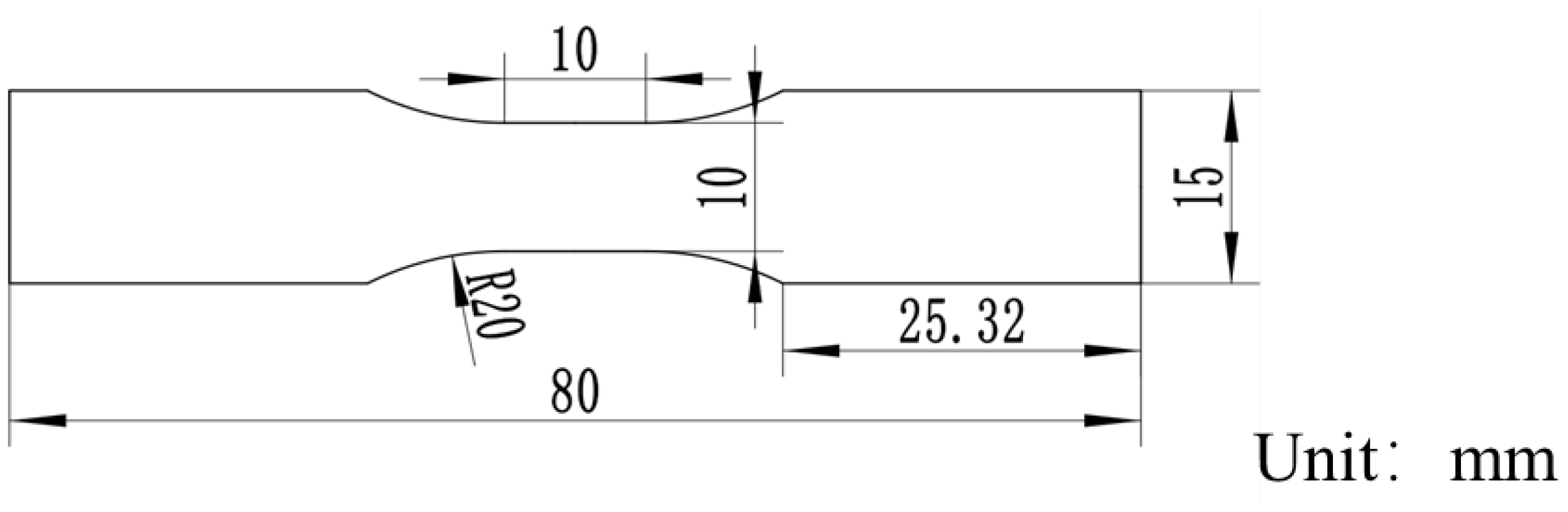
2.2. Methods
3. Results and Discussion
3.1. Stress-Strain Curves of Resins at Different Materials and Strain Rates
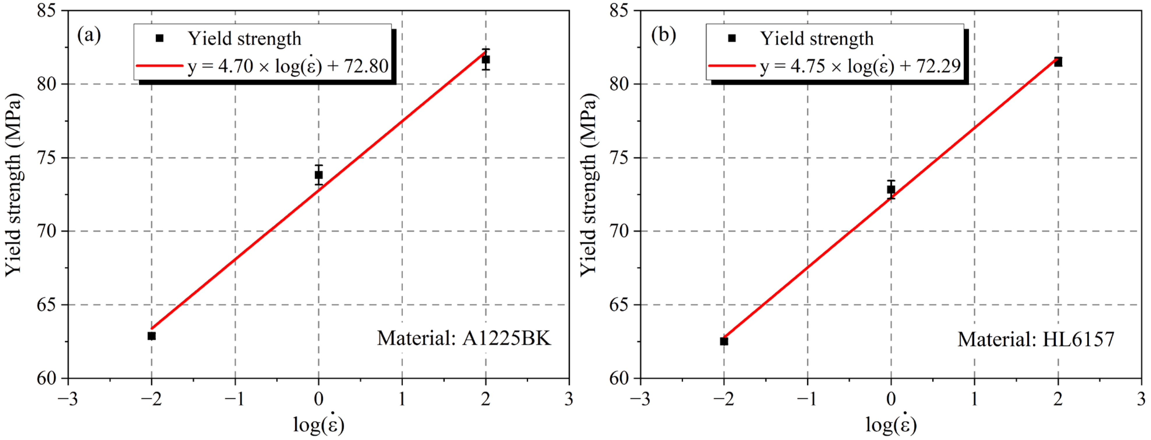
3.2. Effect of Strain Rate on the Mechanical Performance
3.3. DIC Diagram
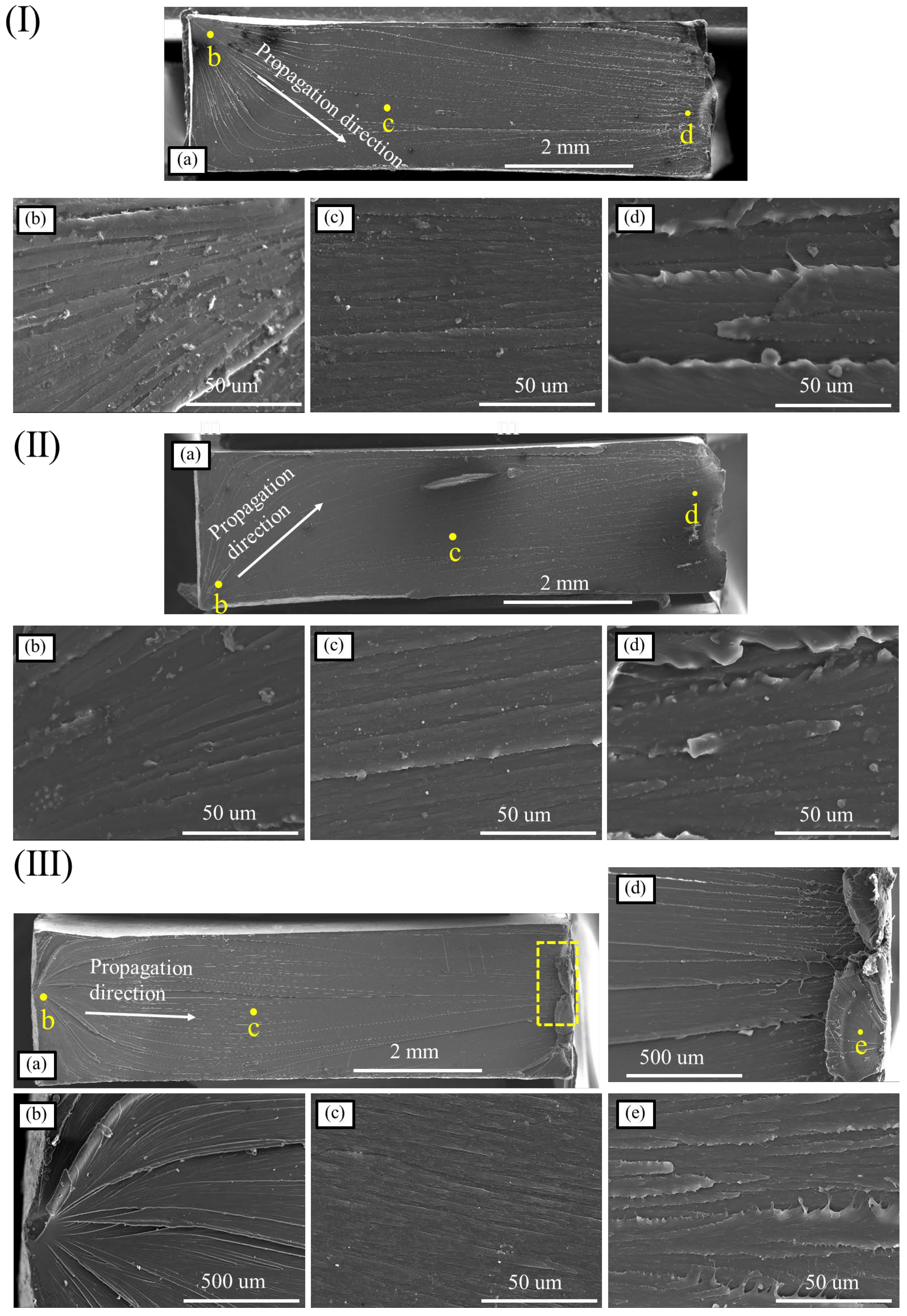
3.4. Microscopic Morphology of the Fracture
4. Conclusions
- In the case of high strain rate, the yield strength and modulus of PC material were significantly improved, and the modulus was proportional to the logarithm of strength and strain rate. At the same time, for the A1225BK and HL6157 materials, with the increase in strain rate, the fracture strain increase was greater than 10% and the yield strength increased by 30%.
- The microscopic characteristics of the fracture of PC material showed that the A1225BK and HL6157 materials still followed the law of ductile fracture at high strain rates, such as the resin residue at the break, which proves that they have good energy absorption ability and good fracture toughness at high strain rates.
- As the matrix for composite materials, A1225BK and HL6157 have good fracture toughness, which can be used to improve the overall impact resistance while meeting the lightweight design of automotives. Additionally, the higher stiffness and higher fracture strain make A1225BK more suitable for the design.
Author Contributions
Funding
Institutional Review Board Statement
Informed Consent Statement
Data Availability Statement
Conflicts of Interest
References
- Feng, M. Development and applications of new materials in automotive lightweighting technologies. Automot. Eng. 2006, 28, 213–220. [Google Scholar] [CrossRef]
- Meng, L. Overview of lightweight technology for new energy vehicles. Automot. Eng. 2019, 6, 15–17. [Google Scholar]
- Du, B.; Li, Q.; Zheng, C.; Wang, S.; Gao, C.; Chen, L. Application of Lightweight Structure in Automobile Bumper Beam: A Review. Materials 2023, 16, 967. [Google Scholar] [CrossRef] [PubMed]
- Rana, A.K.; Guleria, S.; Gupta, V.K.; Thakur, V.K. Cellulosic pine needles-based biorefinery for a circular bioeconomy. Bioresour. Technol. 2023, 367, 128255. [Google Scholar] [CrossRef] [PubMed]
- Singha, A.S.; Rana, A.K. Preparation and characterization of graft copolymerized Cannabis indica L. fiber-reinforced unsaturated polyester matrix-based biocomposites. J. Reinf. Plast. Compos. 2012, 31, 1538–1553. [Google Scholar] [CrossRef]
- Bogenfeld, R.; Kreikemeier, J.; Wille, T. Review and benchmark study on the analysis of low-velocity impact on composite laminates. Eng. Fail. Anal. 2018, 86, 72–99. [Google Scholar] [CrossRef]
- Abrate, S. Impact on Laminated Composite Materials. Appl. Mech. Rev. 1991, 44, 155–190. [Google Scholar] [CrossRef]
- Kokoshvili, S.M.; Tamuzh, V.P. Effect of strain rate on the mechanical properties of polyformaldehyde. Polym. Mech. 1966, 2, 600–602. [Google Scholar] [CrossRef]
- Xiu, L.; Wenbo, L.; Boyuan, Y. Strain-Amplitude and Strain-Rate Dependent Craze Damage of Poly(Methyl Methacrylate). Polym. Polym. Compos. 2014, 22, 737–742. [Google Scholar] [CrossRef]
- Hosur, M.V.; Karim, M.R.; Jeelani, S. On the Response of Stitched Woven S2-Glass/Epoxy Composites to High Strain Rate Compression Loading. Polym. Polym. Compos. 2004, 12, 183–196. [Google Scholar] [CrossRef]
- Sarva, S.; Boyce, M. Mechanics of polycarbonate during high-rate tension. J. Mech. Mater. Struct. 2007, 2, 1853–1880. [Google Scholar] [CrossRef]
- Wang, B.; Wang, T.; Xiang, N.; Yong, G.; Lang, J.; Sun, Q.; Chen, H.; Yan, Y. Mechanical properties of polycarbonate under intermediate strain rates compression. J. Mater. Eng. 2021, 49, 147–155. [Google Scholar]
- Li, Y.; Gao, Y. Study on dynamic mechanical properties of polycarbonate at high strain rates. J. Ordnance Equip. Eng. 2019, 40, 195–199. [Google Scholar]
- Zhu, T.; Li, X.; Yang, H.; Zhe, D.; Wu, P. Tensile behaviors of polypropylene resins under high tensile strain rates. Plastics 2018, 47, 114–118. [Google Scholar]
- Yu, P.; Yao, X.; Zhang, X.; Han, Q. Mechanical behaviors and constitutive models of polycarbonate amorphous polymers. Adv. Mech. 2016, 46, 140–178. [Google Scholar]
- Liu, F.; Li, Q.M. Strain-rate effect of polymers and correction methodology in a SHPB test. Int. J. Impact Eng. 2022, 161, 104109. [Google Scholar] [CrossRef]
- Yang, M.; Li, W.; Dong, P.; Ma, Y.; He, Y.; Zhao, Z.; Chen, L. Temperature and strain rate sensitivity of yield strength of amorphous polymers: Characterization and modeling. Polymer 2022, 251, 124936. [Google Scholar] [CrossRef]


| Density (g/cm3) | Processing Temperature °C | Mold Temperature °C | Time h |
|---|---|---|---|
| 1.18~1.20 | 240~250 | 50~80 | 8~10 |
Disclaimer/Publisher’s Note: The statements, opinions and data contained in all publications are solely those of the individual author(s) and contributor(s) and not of MDPI and/or the editor(s). MDPI and/or the editor(s) disclaim responsibility for any injury to people or property resulting from any ideas, methods, instructions or products referred to in the content. |
© 2023 by the authors. Licensee MDPI, Basel, Switzerland. This article is an open access article distributed under the terms and conditions of the Creative Commons Attribution (CC BY) license (https://creativecommons.org/licenses/by/4.0/).
Share and Cite
Zhang, S.; Wang, B.; Meng, X.; Chen, Y. Mechanical Properties and Fracture Microstructure of Polycarbonate under High Strain Rate Tension. Materials 2023, 16, 3386. https://doi.org/10.3390/ma16093386
Zhang S, Wang B, Meng X, Chen Y. Mechanical Properties and Fracture Microstructure of Polycarbonate under High Strain Rate Tension. Materials. 2023; 16(9):3386. https://doi.org/10.3390/ma16093386
Chicago/Turabian StyleZhang, Sai, Bingqian Wang, Xianming Meng, and Yajun Chen. 2023. "Mechanical Properties and Fracture Microstructure of Polycarbonate under High Strain Rate Tension" Materials 16, no. 9: 3386. https://doi.org/10.3390/ma16093386