
Comparison of Implant Surgery Methods of Cortical Tapping and Cortical Widening in Bone of Various Density: A Three-Dimensional Finite Element Study

Abstract
:1. Introduction
2. Materials and Methods
3. Results
4. Discussion
5. Conclusions
Author Contributions
Funding
Institutional Review Board Statement
Informed Consent Statement
Data Availability Statement
Conflicts of Interest
References
- Ryu, H.-S.; Namgung, C.; Heo, Y.-K.; Lee, J.-H.; Lim, Y.-J. Early loading of splinted implants supporting a two-unit fixed partial denture in the posterior maxilla: 13-month results from a randomized controlled clinical trial of two different implant systems. Clin. Oral Implant. Res. 2016, 27, 1017–1025. [Google Scholar] [CrossRef] [PubMed]
- Simunek, A.; Strnad, J.; Kopecka, D.; Brazda, T.; Pilathadka, S.; Chauhan, R.; Slezak, R.; Capek, L. Changes in stability after healing of immediately loaded dental implants. Int. J. Oral Maxillofac. Implants 2010, 25, 1085–1092. [Google Scholar] [PubMed]
- Atsumi, M.; Park, S.-H.; Wang, H.-L. Methods used to assess implant stability: Current status. Int. J. Oral Maxillofac. Implants 2007, 22, 743–754. [Google Scholar] [PubMed]
- Alghamdi, H.; Anand, P.S.; Anil, S. Undersized Implant Site Preparation to Enhance Primary Implant Stability in Poor Bone Density: A Prospective Clinical Study. J. Oral Maxillofac. Surg. 2011, 69, e506–e512. [Google Scholar] [CrossRef] [PubMed]
- Albrektsson, T. Is surgical skill more important for clinical success than changes in implant hardware? Clin. Implant. Dent. Relat. Res. 2001, 3, 174–175. [Google Scholar] [CrossRef]
- Kim, D.-R.; Lim, Y.-J.; Kim, M.-J.; Kwon, H.-B.; Kim, S.-H. Self-cutting blades and their influence on primary stability of tapered dental implants in a simulated low-density bone model: A laboratory study. Oral Surg. Oral Med. Oral Pathol. Oral Radiol. Endodontol. 2011, 112, 573–580. [Google Scholar] [CrossRef]
- Tabassum, A.; Meijer, G.J.; Wolke, J.G.; Jansen, J.A. Influence of surgical technique and surface roughness on the primary stability of an implant in artificial bone with different cortical thickness: A laboratory study. Clin. Oral Implant. Res. 2010, 21, 213–220. [Google Scholar] [CrossRef]
- Coelho, P.G.; Granato, R.; Marin, C.; Teixeira, H.S.; Suzuki, M.; Valverde, G.B.; Janal, M.N.; Lilin, T.; Bonfante, E.A. The effect of different implant macrogeometries and surface treatment in early biomechanical fixation: An experimental study in dogs. J. Mech. Behav. Biomed. Mater. 2011, 4, 1974–1981. [Google Scholar] [CrossRef]
- Dos Santos, M.V.; Elias, C.N.; Cavalcanti Lima, J.H. The effects of superficial roughness and design on the primary stability of dental implants. Clin. Implant. Dent. Relat. Res. 2011, 13, 215–223. [Google Scholar] [CrossRef]
- Elias, C.N.; Oshida, Y.; Lima, J.H.C.; Muller, C.A. Relationship between surface properties (roughness, wettability and morphology) of titanium and dental implant removal torque. J. Mech. Behav. Biomed. Mater. 2008, 1, 234–242. [Google Scholar] [CrossRef]
- Hong, J.; Lim, Y.-J.; Park, S.-O. Quantitative biomechanical analysis of the influence of the cortical bone and implant length on primary stability. Clin. Oral Implant. Res. 2012, 23, 1193–1197. [Google Scholar] [CrossRef] [PubMed]
- Östman, P.-O.; Hellman, M.; Wendelhag, I.; Sennerby, L. Resonance frequency analysis measurements of implants at placement surgery. Int. J. Prosthodont. 2006, 19, 77–83, discussion 84. [Google Scholar] [PubMed]
- Wang, Y.; Zhang, Y.; Miron, R.J. Health, Maintenance, and Recovery of Soft Tissues around Implants. Clin. Implant. Dent. Relat. Res. 2016, 18, 618–634. [Google Scholar] [CrossRef] [PubMed]
- Mosavar, A.; Ziaei, A.; Kadkhodaei, M. The Effect of Implant Thread Design on Stress Distribution in Anisotropic Bone with Different Osseointegration Conditions: A Finite Element Analysis. Int. J. Oral Maxillofac. Implants 2015, 30, 1317–1326. [Google Scholar] [CrossRef]
- Tabassum, A.; Meijer, G.J.; Walboomers, X.F.; Jansen, J.A. Evaluation of primary and secondary stability of titanium implants using different surgical techniques. Clin. Oral Implant. Res. 2014, 25, 487–492. [Google Scholar] [CrossRef]
- Winwood, K.; Zioupos, P.; Currey, J.D.; Cotton, J.; Taylor, M. The importance of the elastic and plastic components of strain in tensile and compressive fatigue of human cortical bone in relation to orthopaedic biomechanics. J. Musculoskelet. Neuronal Interact. 2006, 6, 134–141. [Google Scholar]
- Brancacci, E.; González, S.G.; Galve-Huertas, A.; Bennani, A.; Alfaro, F.H.; Centenero, S.A.-H. Influence of Insertion Torques on the Surface Integrity in Different Dental Implants: An Ex Vivo Descriptive Study. Materials 2023, 16, 2330. [Google Scholar] [CrossRef]
- Bashutski, J.D.; D’Silva, N.J.; Wang, H.-L. Implant Compression Necrosis: Current Understanding and Case Report. J. Periodontol. 2009, 80, 700–704. [Google Scholar] [CrossRef]
- Hansson, S.; Werke, M. The implant thread as a retention element in cortical bone: The effect of thread size and thread profile: A finite element study. J. Biomech. 2003, 36, 1247–1258. [Google Scholar] [CrossRef]
- Brånemark, P.I.; Hansson, B.O.; Adell, R.; Breine, U.; Lindström, J.; Hallén, O.; Ohman, A. Osseointegrated implants in the treatment of the edentulous jaw. Experience from a 10-year period. Scand. J. Plast. Reconstr. Surg. Suppl. 1977, 16, 1–132. [Google Scholar]
- O’Sullivan, D.; Sennerby, L.; Meredith, N. Influence of implant taper on the primary and secondary stability of osseointegrated titanium implants. Clin. Oral Implant. Res. 2004, 15, 474–480. [Google Scholar] [CrossRef] [PubMed]
- Adell, R.; Lekholm, U.; Rockler, B.; Brånemark, P.-I. A 15-year study of osseointegrated implants in the treatment of the edentulous jaw. Int. J. Oral Surg. 1981, 10, 387–416. [Google Scholar] [CrossRef]
- Albrektsson, T.; Brånemark, P.-I.; Hansson, H.-A.; Lindström, J. Osseointegrated titanium implants: Requirements for ensuring a long-lasting, direct bone-to-implant anchorage in man. Acta Orthop. Scand. 1981, 52, 155–170. [Google Scholar] [CrossRef] [PubMed]
- O’Sullivan, D.; Sennerby, L.; Meredith, N. Measurements comparing the initial stability of five designs of dental implants: A human cadaver study. Clin. Implant. Dent. Relat. Res. 2000, 2, 85–92. [Google Scholar] [CrossRef] [PubMed]
- Heo, D.; Heo, Y.-K.; Lee, J.-H.; Lee, J.-J.; Kim, B. Comparison Between Cortical Drill and Cortical Tap and Their Influence on Primary Stability of Macro-Thread Tapered Implant in Thin Crestal Cortical Bone and Low-Density Bone. Implant. Dent. 2017, 26, 711–717. [Google Scholar] [CrossRef]
- Kim, W.H.; Lee, J.-C.; Lim, D.; Heo, Y.-K.; Song, E.-S.; Lim, Y.-J.; Kim, B. Optimized Dental Implant Fixture Design for the Desirable Stress Distribution in the Surrounding Bone Region: A Biomechanical Analysis. Materials 2019, 12, 2749. [Google Scholar] [CrossRef] [PubMed]
- Kim, W.H.; Song, E.S.; Ju, K.W.; Lee, J.-H.; Kim, M.Y.; Lim, D.; Kim, B. Finite Element Analysis of Novel Separable Fixture for Easy Retrievement in Case with Peri-Implantitis. Materials 2019, 12, 235. [Google Scholar] [CrossRef]
- Premnath, K.; Sridevi, J.; Kalavathy, N.; Nagaranjani, P.; Sharmila, M.R. Evaluation of Stress Distribution in Bone of Different Densities Using Different Implant Designs: A Three-Dimensional Finite Element Analysis. J. Indian Prosthodont. Soc. 2013, 13, 555–559. [Google Scholar] [CrossRef] [PubMed]
- Chugh, T.; Jain, A.K.; Jaiswal, R.K.; Mehrotra, P.; Mehrotra, R. Bone density and its importance in orthodontics. J. Oral Biol. Craniofacial Res. 2013, 3, 92–97. [Google Scholar] [CrossRef]
- Kravitz, N.D.; Kusnoto, B. Risks and complications of orthodontic miniscrews. Am. J. Orthod. Dentofac. Orthop. 2007, 131, S43–S51. [Google Scholar] [CrossRef]
- Sevimay, M.; Turhan, F.; Kiliçarslan, M.; Eskitascioglu, G. Three-dimensional finite element analysis of the effect of different bone quality on stress distribution in an implant-supported crown. J. Prosthet. Dent. 2005, 93, 227–234. [Google Scholar] [CrossRef] [PubMed]
- Yalçın, M.; Kaya, B.; Laçin, N.; Arı, E. Three-Dimensional Finite Element Analysis of the Effect of Endosteal Implants with Different Macro Designs on Stress Distribution in Different Bone Qualities. Int. J. Oral Maxillofac. Implants 2019, 34, e43–e50. [Google Scholar] [CrossRef] [PubMed]
- Tribst, J.P.M.; Piva, A.M.D.O.D.; Rodrigues, V.A.; Borges, A.L.S.; Nishioka, R.S. Stress and strain distributions on short implants with two different prosthetic connections—An in vitro and in silico analysis. Braz. Dent. Sci. 2017, 20, 101–109. [Google Scholar] [CrossRef]
- Ao, J.; Li, T.; Liu, Y.; Ding, Y.; Wu, G.; Hu, K.; Kong, L. Optimal design of thread height and width on an immediately loaded cylinder implant: A finite element analysis. Comput. Biol. Med. 2010, 40, 681–686. [Google Scholar] [CrossRef]
- Graf, H.; Geering, A.H. Rationale for clinical application of different occlusal philosophies. Oral Sci. Rev. 1977, 10, 1–10. [Google Scholar]
- Mellal, A.; Wiskott, H.; Botsis, J.; Scherrer, S.; Belser, U. Stimulating effect of implant loading on surrounding bone: Comparison of three numerical models and validation by in vivo data. Clin. Oral Implants Res. 2004, 15, 239–248. [Google Scholar] [CrossRef]
- Zhang, G.; Yuan, H.; Chen, X.; Wang, W.; Chen, J.; Liang, J.; Zhang, P. A Three-Dimensional Finite Element Study on the Biomechanical Simulation of Various Structured Dental Implants and Their Surrounding Bone Tissues. Int. J. Dent. 2016, 2016, 4867402. [Google Scholar] [CrossRef]
- Chung, S.H.; Heo, S.J.; Koak, J.Y.; Kim, S.K.; Lee, J.B.; Han, J.S.; Han, C.H.; Rhyu, I.C.; Lee, S.J. Effects of implant geometry and surface treatment on osseointegration after functional loading: A dog study. J. Oral Rehabil. 2008, 35, 229–236. [Google Scholar] [CrossRef]


| Types | Materials | Young’s Modulus (MPa) | Poisson’s Ratio |
|---|---|---|---|
| Bone | D1 | 9500 | 0.3 |
| D4 | 690 | 0.3 | |
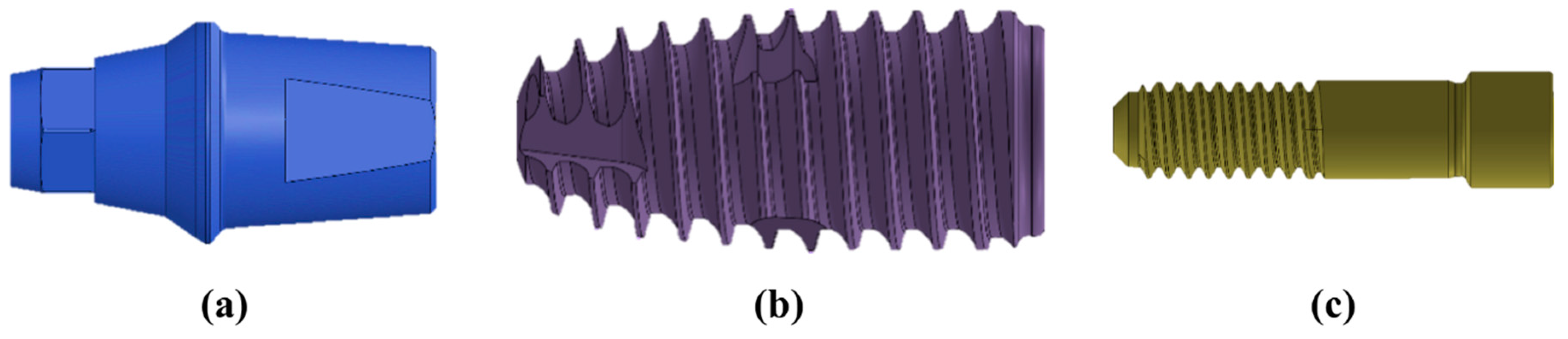
| Abutment | Ti-grade 5 | 114,000 | 0.33 |
| Fixture | Ti-grade 4 | 105,000 | 0.34 |
| Abutment Screw | Ti-grade 5 | 114,000 | 0.33 |
| Crown | Zirconia | 205,000 | 0.19 |
| Cement | Resin | 10,310 | 0.35 |
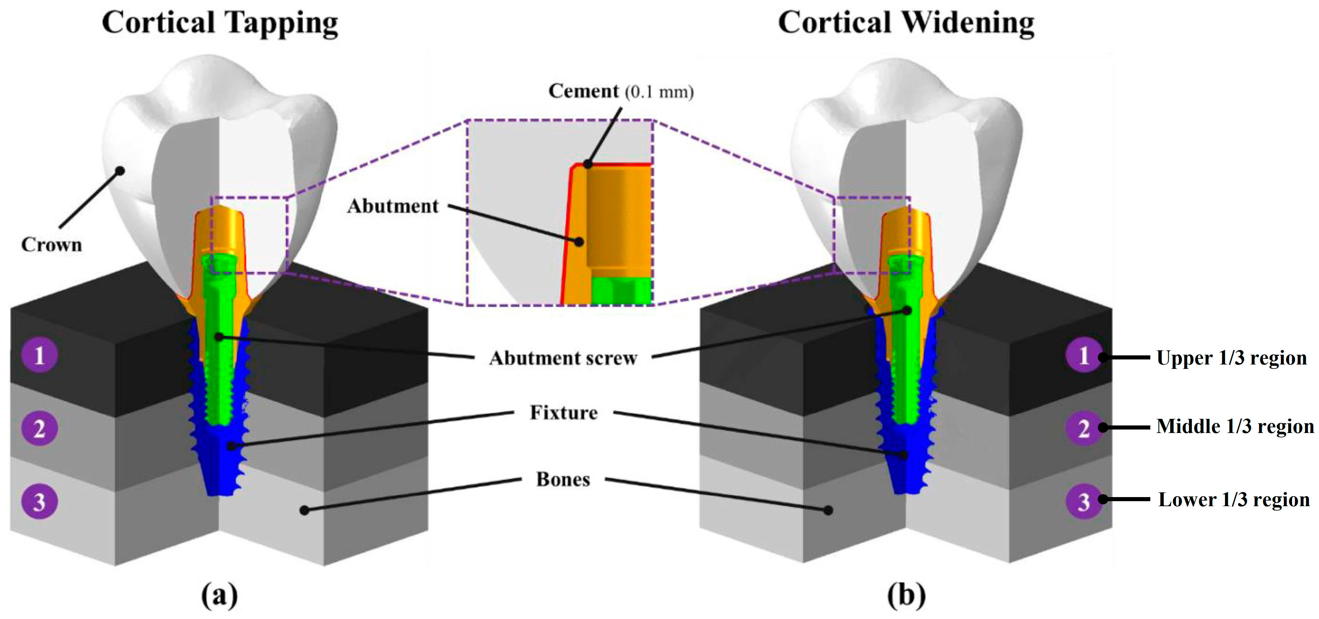
| Types | Region ① | Region ② | Region ③ |
|---|---|---|---|
| D111 | D1 | D1 | D1 |
| D144 | D1 | D4 | D4 |
| D414 | D4 | D1 | D4 |
| D441 | D4 | D4 | D1 |
| D444 | D4 | D4 | D4 |
| Components | Elements | Nodes | Mesh Size (mm) | |
|---|---|---|---|---|
| Maximum | Minimum | |||
| Bone (widening) | 398,016 | 72,982 | 0.75 | 0.15 |
| Bone (tapping) | 386,123 | 71,233 | 0.75 | 0.15 |
| Abutment | 541,131 | 118,764 | 0.15 | 0.03 |
| Fixture | 790,066 | 146,527 | 0.15 | 0.03 |
| Abutment Screw | 502,530 | 93,818 | 0.15 | 0.03 |
| Crown | 147,556 | 30,528 | 0.3 | 0.15 |
| Cement | 42,608 | 14,282 | 0.1 | 0.03 |
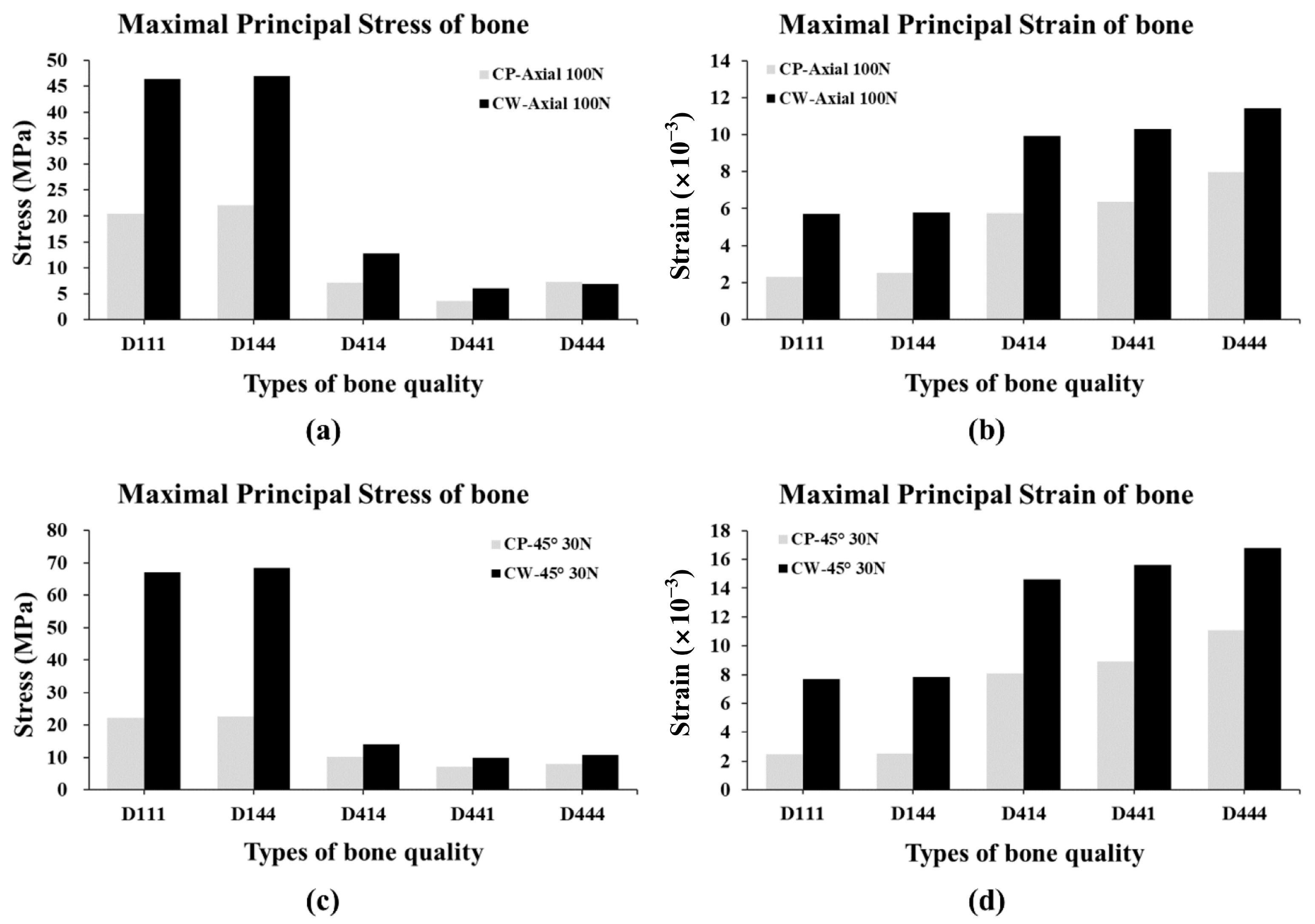
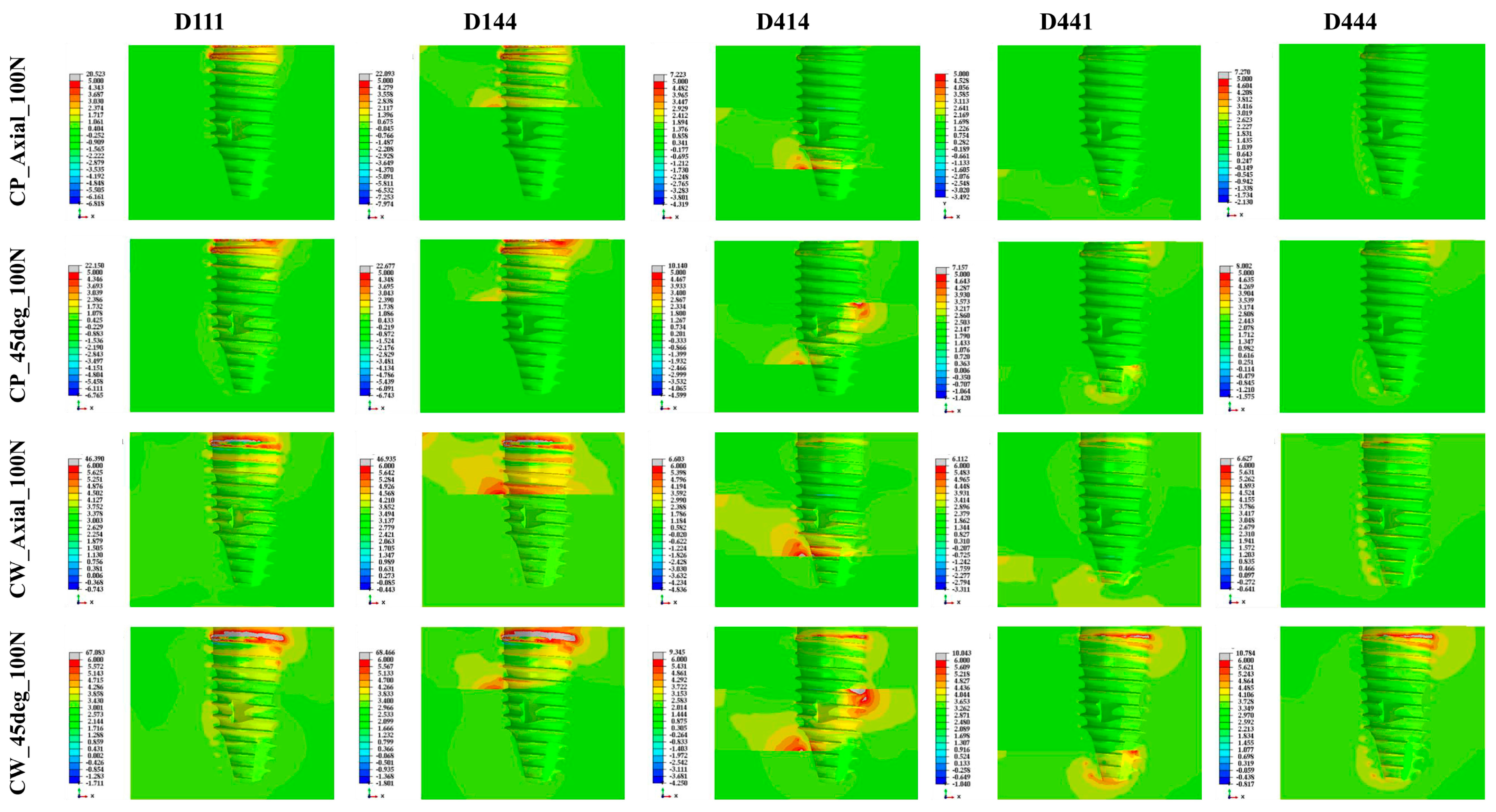
| Type of Loading | Bone Quality | Maximal Principal Stress (MPa) | |
| CP | CW | ||
| 100 N at axial direction | D111 | 20.52 | 46.39 |
| D144 | 22.09 | 46.94 | |
| D414 | 7.22 | 12.82 | |
| D441 | 3.71 | 6.11 | |
| D444 | 7.27 | 6.96 | |
| 30 N at 45 degrees | D111 | 22.15 | 67.08 |
| D144 | 22.68 | 68.47 | |
| D414 | 10.14 | 14.02 | |
| D441 | 7.16 | 10.04 | |
| D444 | 8.01 | 10.78 | |
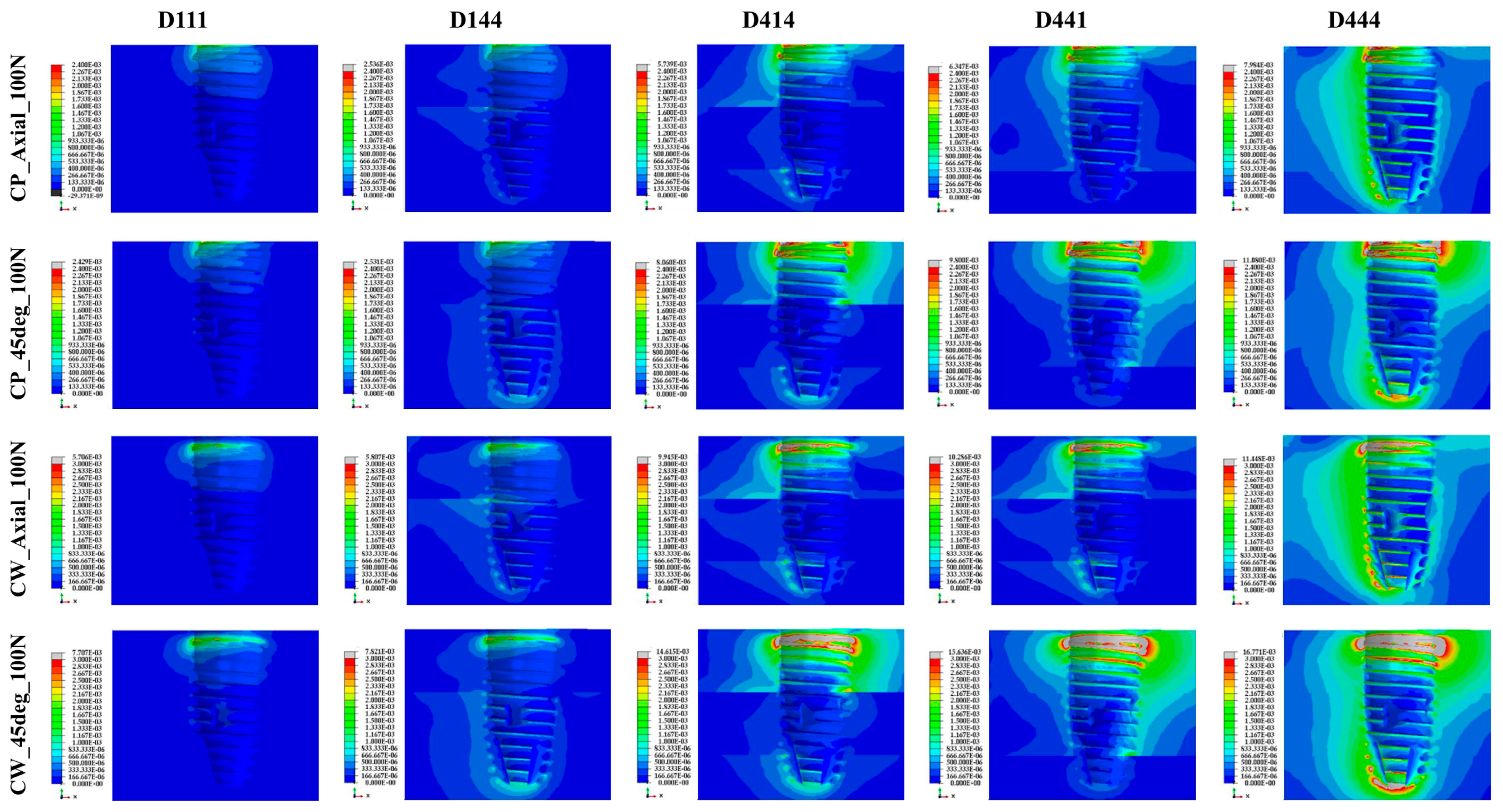
| Type of Loading | Bone Quality | Maximal Principal Strain (×10−3) | |
| CP | CW | ||
| 100 N at axial direction | D111 | 2.29 | 5.71 |
| D144 | 2.54 | 5.81 | |
| D414 | 5.74 | 9.95 | |
| D441 | 6.35 | 10.29 | |
| D444 | 7.98 | 11.45 | |
| 30 N at 45 degrees | D111 | 2.46 | 7.71 |
| D144 | 2.53 | 7.82 | |
| D414 | 8.06 | 14.62 | |
| D441 | 8.90 | 15.64 | |
| D444 | 11.08 | 16.77 | |
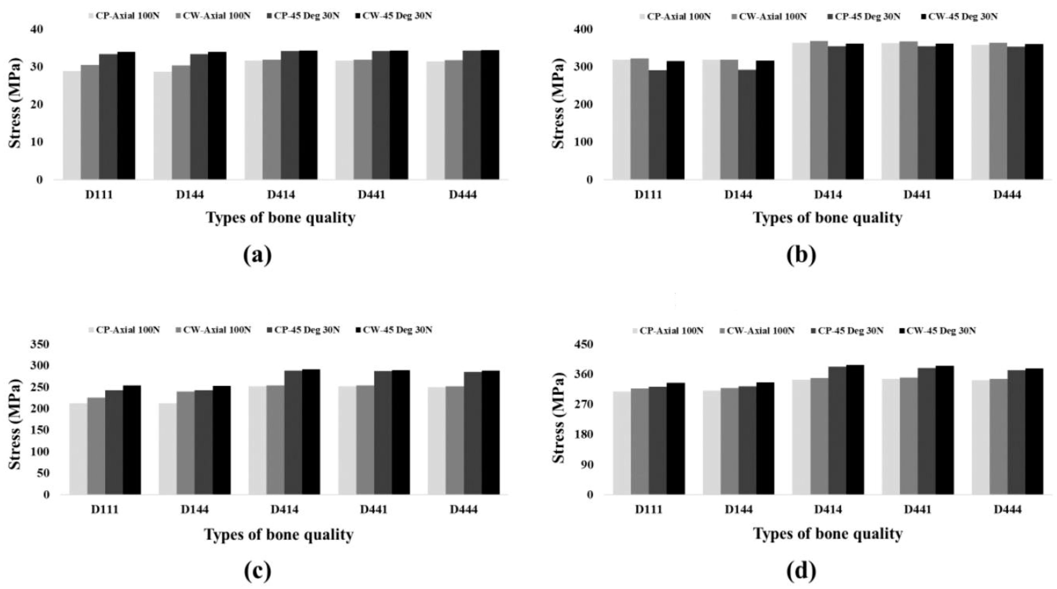
| Component | Type of Loading | Bone Quality | PVMS (MPa) | |
|---|---|---|---|---|
| CP | CW | |||
| Abutment | 100 N at axial direction | D111 | 318.88 | 321.73 |
| D144 | 364.34 | 319.12 | ||
| D414 | 364.34 | 368.82 | ||
| D441 | 362.28 | 367.06 | ||
| D444 | 358.28 | 364.16 | ||
| 30 N at 45 degrees | D111 | 290.47 | 314.71 | |
| D144 | 291.85 | 316.62 | ||
| D414 | 354.94 | 361.05 | ||
| D441 | 354.51 | 361.08 | ||
| D444 | 353.53 | 360.61 | ||
| Fixture | 100 N at axial direction | D111 | 212.34 | 225.32 |
| D144 | 212.03 | 239.54 | ||
| D414 | 251.48 | 253.60 | ||
| D441 | 251.29 | 253.29 | ||
| D444 | 249.38 | 251.27 | ||
| 30 N at 45 degrees | D111 | 242.29 | 253.11 | |
| D144 | 242.42 | 252.59 | ||
| D414 | 288.21 | 290.65 | ||
| D441 | 286.75 | 288.94 | ||
| D444 | 285.27 | 287.40 | ||
| Crown | 100 N at axial direction | D111 | 28.84 | 30.48 |
| D144 | 28.66 | 30.34 | ||
| D414 | 31.66 | 31.89 | ||
| D441 | 31.59 | 31.83 | ||
| D444 | 31.45 | 31.78 | ||
| 30 N at 45 degrees | D111 | 33.36 | 33.90 | |
| D144 | 33.38 | 33.91 | ||
| D414 | 34.22 | 34.30 | ||
| D441 | 34.22 | 34.31 | ||
| D444 | 34.24 | 34.35 | ||
| Screw | 100 N at axial direction | D111 | 307.93 | 316.36 |
| D144 | 309.83 | 317.9 | ||
| D414 | 343.44 | 347.47 | ||
| D441 | 346.03 | 349.76 | ||
| D444 | 341.50 | 345.22 | ||
| 30 N at 45 degrees | D111 | 321.66 | 333.93 | |
| D144 | 323.20 | 334.69 | ||
| D414 | 381.33 | 387.40 | ||
| D441 | 378.52 | 384.32 | ||
| D444 | 371.03 | 376.68 | ||
Disclaimer/Publisher’s Note: The statements, opinions and data contained in all publications are solely those of the individual author(s) and contributor(s) and not of MDPI and/or the editor(s). MDPI and/or the editor(s) disclaim responsibility for any injury to people or property resulting from any ideas, methods, instructions or products referred to in the content. |
© 2023 by the authors. Licensee MDPI, Basel, Switzerland. This article is an open access article distributed under the terms and conditions of the Creative Commons Attribution (CC BY) license (https://creativecommons.org/licenses/by/4.0/).
Share and Cite
Baek, Y.-W.; Lim, Y.-J.; Kim, B. Comparison of Implant Surgery Methods of Cortical Tapping and Cortical Widening in Bone of Various Density: A Three-Dimensional Finite Element Study. Materials 2023, 16, 3261. https://doi.org/10.3390/ma16083261
Baek Y-W, Lim Y-J, Kim B. Comparison of Implant Surgery Methods of Cortical Tapping and Cortical Widening in Bone of Various Density: A Three-Dimensional Finite Element Study. Materials. 2023; 16(8):3261. https://doi.org/10.3390/ma16083261
Chicago/Turabian StyleBaek, Yeon-Wha, Young-Jun Lim, and Bongju Kim. 2023. "Comparison of Implant Surgery Methods of Cortical Tapping and Cortical Widening in Bone of Various Density: A Three-Dimensional Finite Element Study" Materials 16, no. 8: 3261. https://doi.org/10.3390/ma16083261