
On the Quenching of Electron Temperature in Inductively Coupled Plasma

 ,
,  , , ,
, , , 
Abstract
:1. Introduction
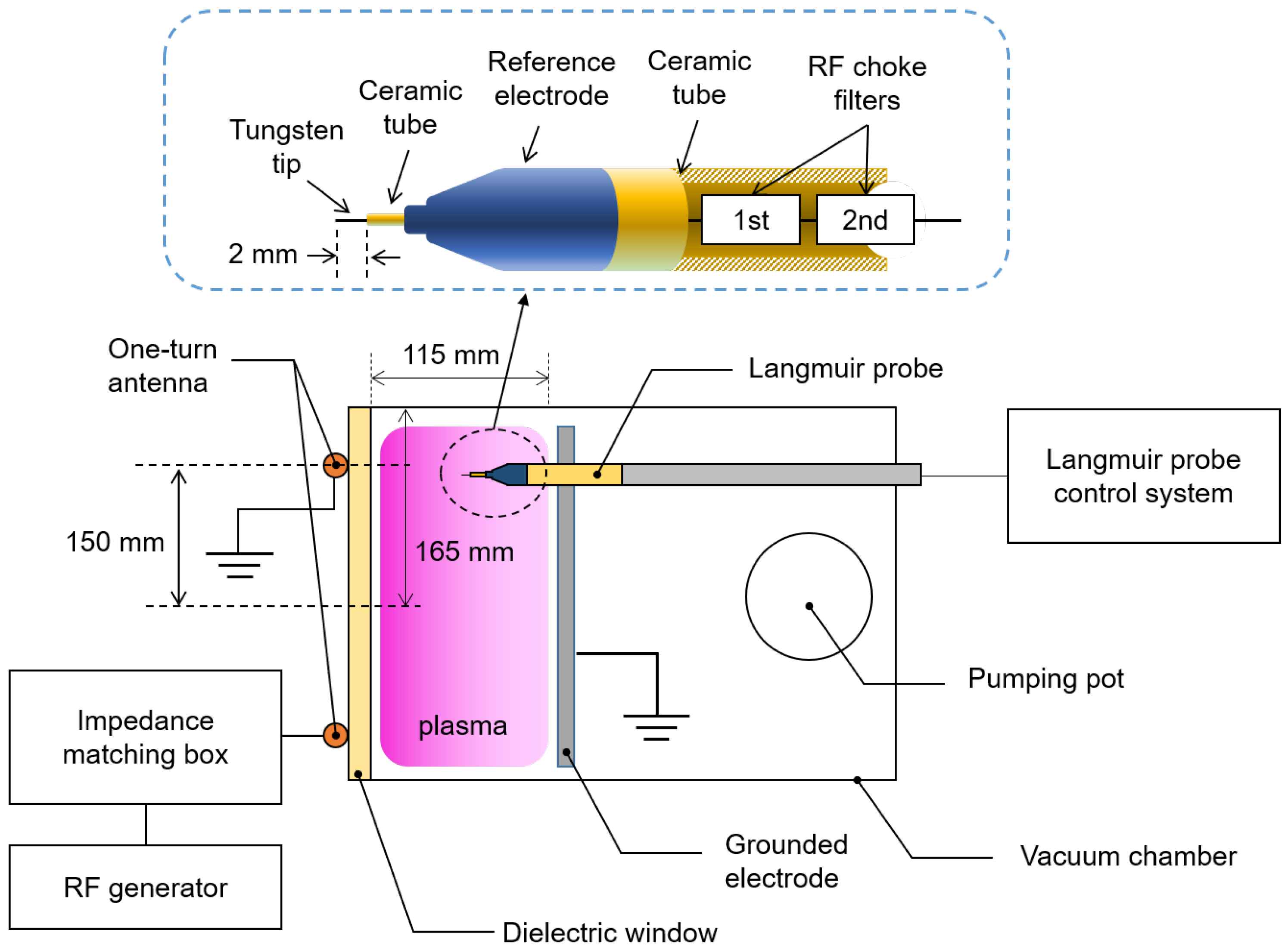
2. Experiment Setup
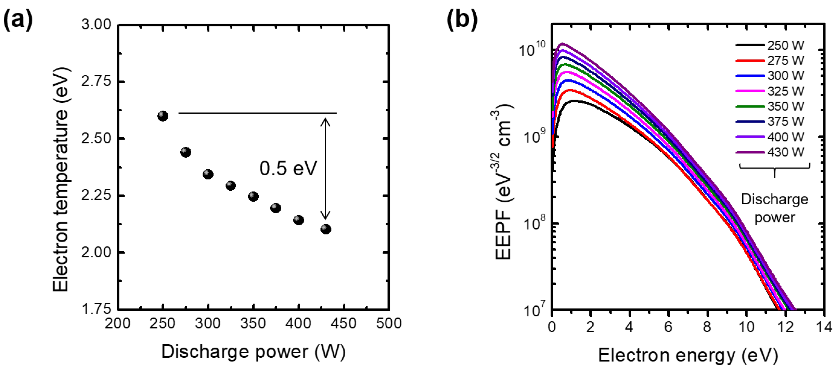
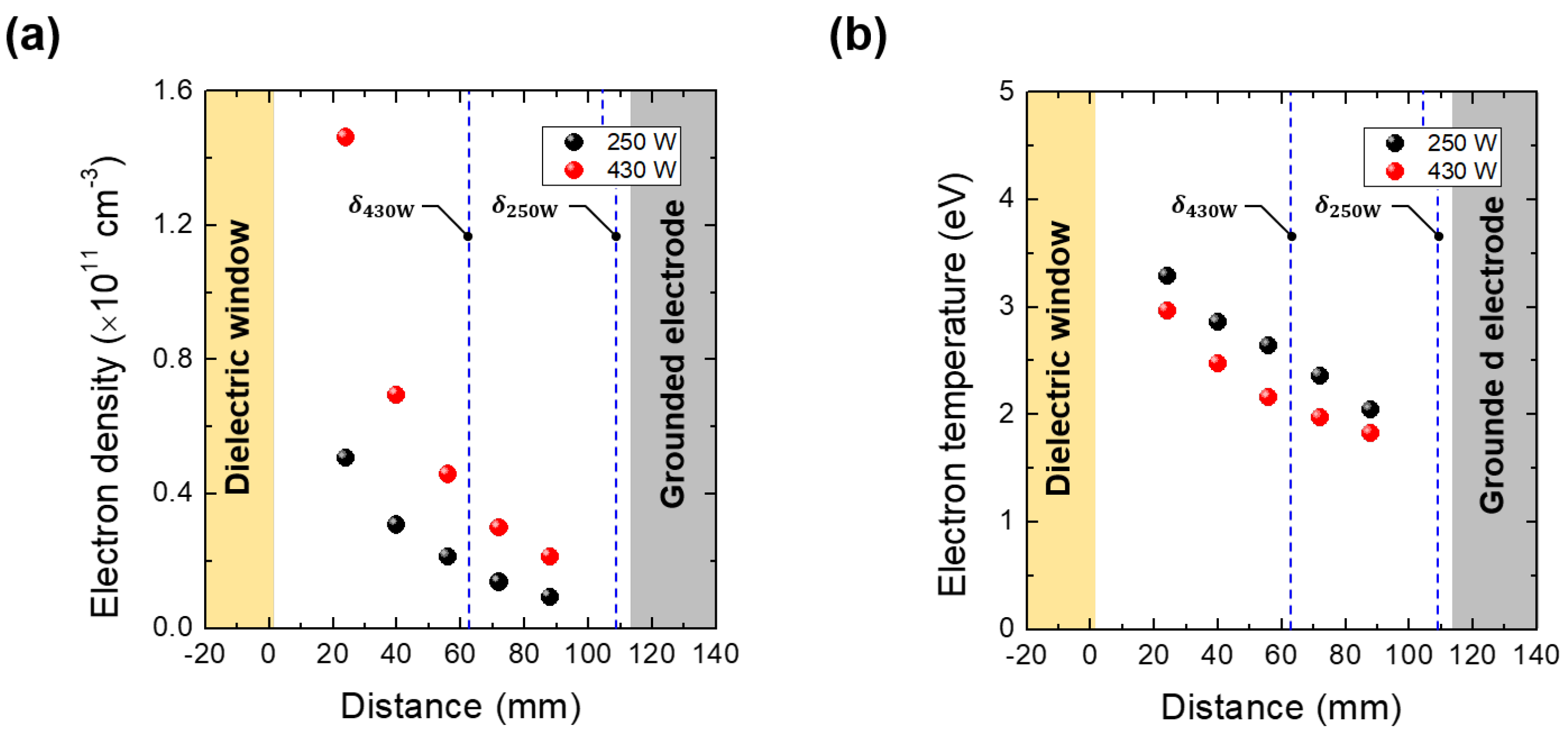
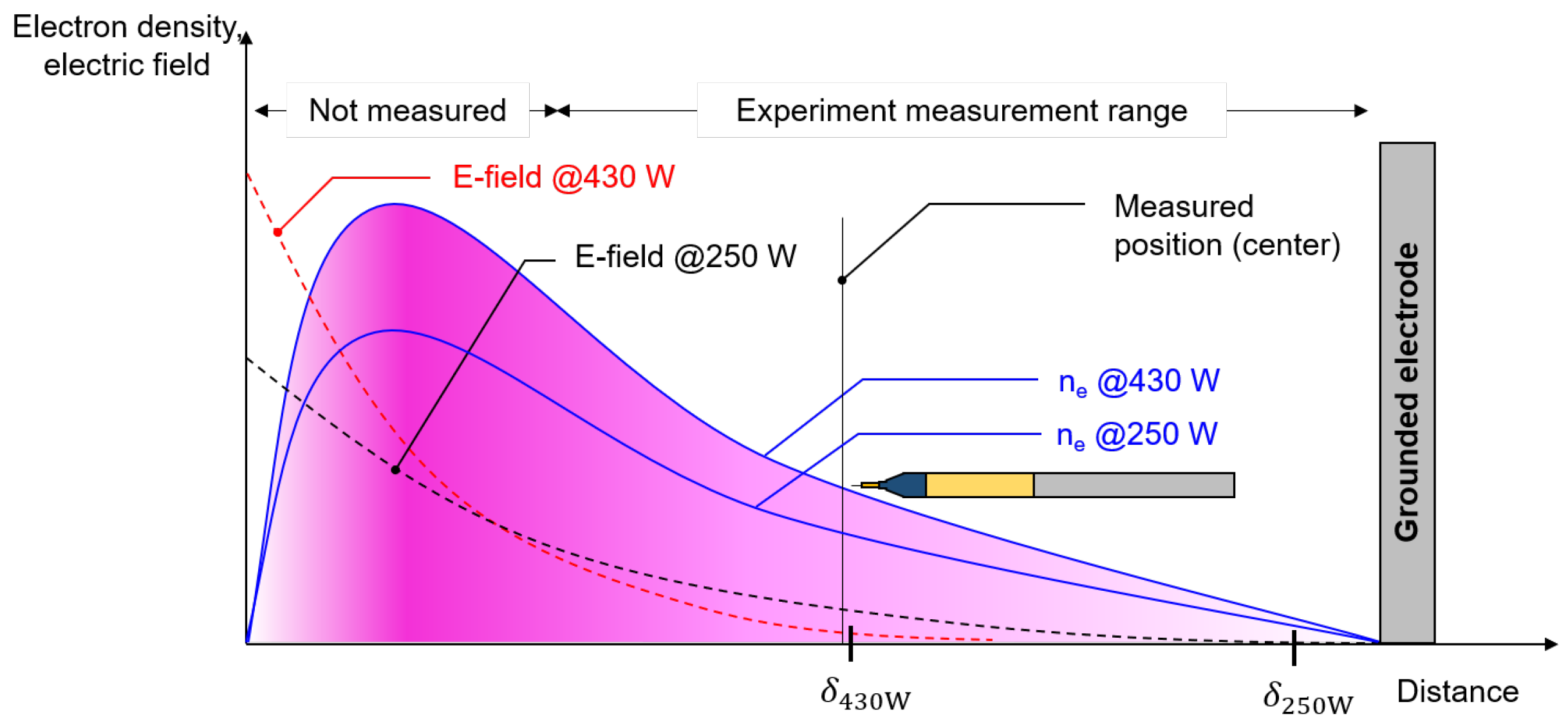
3. Results and Discussion
4. Conclusions
Author Contributions
Funding
Institutional Review Board Statement
Informed Consent Statement
Data Availability Statement
Conflicts of Interest
Appendix A
References
- Racka-Szmidt, K.; Stonio, B.; Żelazko, J.; Filipiak, M.; Sochacki, M. A Review: Inductively Coupled Plasma Reactive Ion Etching of Silicon Carbide. Materials 2022, 15, 123. [Google Scholar] [CrossRef] [PubMed]
- Cho, C.; You, K.; Kim, S.; Lee, Y.; Lee, J.; You, S. Characterization of SiO2 Etching Profiles in Pulse-Modulated Capacitively Coupled Plasmas. Materials 2021, 14, 5036. [Google Scholar] [CrossRef] [PubMed]
- Ishikawa, K.; Karahashi, K.; Ishijima, T.; Cho, S.I.; Elliott, S.; Hausmann, D.; Mocuta, D.; Wilson, A.; Kinoshita, K. Progress in nanoscale dry processes for fabrication of high-aspect-ratio features: How can we control critical dimension uniformity at the bottom? Jpn. J. Appl. Phys. 2018, 57, 06JA01. [Google Scholar] [CrossRef]
- Seong, I.H.; Lee, J.J.; Cho, C.H.; Lee, Y.S.; Kim, S.J.; You, S.J. Characterization of SiO2 Over Poly-Si Mask Etching in Ar/C4F8 Capacitively Coupled Plasma. Appl. Sci. Converg. Technol. 2021, 30, 176–182. [Google Scholar] [CrossRef]
- Lieberman, M.A.; Lichtenberg, A.J. Principles of Plasma Discharges and Materials Processing; John Wiley & Sons: Hoboken, NJ, USA, 2005. [Google Scholar]
- You, Y.B.; Lee, Y.S.; Kim, S.J.; Cho, C.H.; Seong, I.H.; Jeong, W.N.; Choi, M.S.; You, S.J. Influence of Additive N2 on O2 Plasma Ashing Process in Inductively Coupled Plasma. Nanomaterials 2022, 12, 3798. [Google Scholar] [CrossRef] [PubMed]
- Kolobov, V.; Godyak, V. Electron kinetics in low-temperature plasmas. Phys. Plasmas 2019, 26, 060601. [Google Scholar] [CrossRef]
- Lee, H.C. A Brief Review of Electron Kinetics in Radio-Frequency Plasmas. Appl. Sci. Converg. Technol. 2019, 28, 79–81. [Google Scholar] [CrossRef]
- Yeom, W.G.; Song, C.H.; Cho, C.H.; You, S.J.; Yeom, G.Y. Characteristics of Cobalt Thin Films Deposited by Very High Frequency Plasma Enhanced Atomic Layer Deposition (60 and 100 MHz) Using Cobaltocene (Co(Cp)2)/NH3. J. Nanosci. Nanotechnol. 2021, 21, 1826–1832. [Google Scholar] [CrossRef]
- Kim, S.J.; Choi, M.S.; Lee, S.H.; Jeong, W.N.; Lee, Y.S.; Seong, I.H.; Cho, C.H.; Kim, D.W.; You, S.J. Development of the Tele-Measurement of Plasma Uniformity via Surface Wave Information (TUSI) Probe for Non-Invasive In-Situ Monitoring of Electron Density Uniformity in Plasma Display Fabrication Process. Sensors 2023, 23, 2521. [Google Scholar] [CrossRef]
- Kim, S.J.; Lee, S.H.; You, Y.B.; Lee, Y.S.; Seong, I.H.; Cho, C.H.; Lee, J.J.; You, S.J. Development of the Measurement of Lateral Electron Density (MOLE) Probe Applicable to Low-Pressure Plasma Diagnostics. Sensors 2022, 22, 5487. [Google Scholar] [CrossRef]
- Kim, S.J.; Lee, J.J.; Lee, Y.S.; Yeom, H.J.; Lee, H.C.; Kim, J.H.; You, S.J. Computational Characterization of Microwave Planar Cutoff Probes for Non-Invasive Electron Density Measurement in Low-Temperature Plasma: Ring-and Bar-Type Cutoff Probes. Appl. Sci. 2020, 10, 7066. [Google Scholar] [CrossRef]
- Ogawa, D.; Nakamura, K.; Sugai, H. Experimental validity of double-curling probe method in film-depositing plasma. Plasma Sources Sci. Technol. 2021, 30, 085009. [Google Scholar] [CrossRef]
- Wang, C.; Friedrichs, M.; Oberrath, J.; Brinkmann, R.P. Kinetic investigation of the planar multipole resonance probe in the low-pressure plasma. Plasma Sources Sci. Technol. 2021, 30, 105011. [Google Scholar] [CrossRef]
- Lee, M.H.; Jang, S.H.; Chung, C.W. On the multistep ionizations in an argon inductively coupled plasma. Phys. Plasmas 2006, 13, 053502. [Google Scholar] [CrossRef]
- Roth, J.R. Industrial Plasma Engineering: Volume 2: Applications to Nonthermal Plasma Processing; CRC Press: Boca Raton, FL, USA, 2001. [Google Scholar]
- Grill, A. Cold Plasma in Materials Fabrication; IEEE Press: New York, NY, USA, 1994; Volume 151. [Google Scholar]
- Lee, H.C. Review of inductively coupled plasmas: Nano-applications and bistable hysteresis physics. Appl. Phys. Rev. 2018, 5, 011108. [Google Scholar] [CrossRef]
- Godyak, V.; Piejak, R.; Alexandrovich, B. Electron energy distribution function measurements and plasma parameters in inductively coupled argon plasma. Plasma Sources Sci. Technol. 2002, 11, 525. [Google Scholar] [CrossRef]
- Lee, H.C.; Seo, B.; Kwon, D.C.; Kim, J.; Seong, D.; Oh, S.; Chung, C.W.; You, K.; Shin, C. Evolution of electron temperature in inductively coupled plasma. Appl. Phys. Lett. 2017, 110, 014106. [Google Scholar] [CrossRef]
- Lee, M.H.; Chung, C.W. Effect of multistep ionizations on the electron temperature in an argon inductively coupled plasma. Appl. Phys. Lett. 2005, 87, 131502. [Google Scholar] [CrossRef]
- Sudit, I.D.; Chen, F.F. RF compensated probes for high-density discharges. Plasma Sources Sci. Technol. 1994, 3, 162. [Google Scholar] [CrossRef]
- Chabert, P.; Braithwaite, N. Physics of Radio-Frequency Plasmas; Cambridge University Press: Cambridge, UK, 2011; pp. 18–55. [Google Scholar]
- Hopwood, J.; Guarnieri, C.; Whitehair, S.; Cuomo, J. Electromagnetic fields in a radio-frequency induction plasma. J. Vac. Sci. Technol. Vacuum, Surfaces, Film. 1993, 11, 147–151. [Google Scholar] [CrossRef]
- Li, B.; Li, H.; Wang, H.; Xie, J.; Liu, W. Theoretical and experimental study of the microwave cut-off probe for electron density measurements in low-temperature plasmas. J. Appl. Phys. 2011, 110, 073308. [Google Scholar] [CrossRef]
- Xi, Y.B.; Liu, Y. Effect of electron density profile on power absorption of high frequency electromagnetic waves in plasma. Phys. Plasmas 2012, 19, 073301. [Google Scholar]
- Lee, M.H.; Chung, C.W. Self-consistent global model with multi-step ionizations in inductively coupled plasmas. Phys. Plasmas 2005, 12, 073501. [Google Scholar] [CrossRef]
- Kramida, A.; Ralchenko, Y.; Reader, J.; Team, N.A. NIST Atomic Spectra Database (version 5.10). Mem. Della Soc. Astron. Ital. Suppl. 2005, 8, 96. [Google Scholar] [CrossRef]


Disclaimer/Publisher’s Note: The statements, opinions and data contained in all publications are solely those of the individual author(s) and contributor(s) and not of MDPI and/or the editor(s). MDPI and/or the editor(s) disclaim responsibility for any injury to people or property resulting from any ideas, methods, instructions or products referred to in the content. |
© 2023 by the authors. Licensee MDPI, Basel, Switzerland. This article is an open access article distributed under the terms and conditions of the Creative Commons Attribution (CC BY) license (https://creativecommons.org/licenses/by/4.0/).
Share and Cite
Seong, I.; Kim, S.-j.; Lee, Y.; Cho, C.; Jeong, W.; You, Y.; Choi, M.; Choi, B.; You, S. On the Quenching of Electron Temperature in Inductively Coupled Plasma. Materials 2023, 16, 3219. https://doi.org/10.3390/ma16083219
Seong I, Kim S-j, Lee Y, Cho C, Jeong W, You Y, Choi M, Choi B, You S. On the Quenching of Electron Temperature in Inductively Coupled Plasma. Materials. 2023; 16(8):3219. https://doi.org/10.3390/ma16083219
Chicago/Turabian StyleSeong, Inho, Si-jun Kim, Youngseok Lee, Chulhee Cho, Wonnyoung Jeong, Yebin You, Minsu Choi, Byeongyeop Choi, and Shinjae You. 2023. "On the Quenching of Electron Temperature in Inductively Coupled Plasma" Materials 16, no. 8: 3219. https://doi.org/10.3390/ma16083219