
Preparation and Lubricating Properties of Polystyrene Composite Microspheres

Abstract
:1. Introduction
2. Materials and Methods
2.1. Materials
2.2. Preparation of Composite Microspheres
2.2.1. Preparation of EGR/PS
2.2.2. Preparation of OMMT/EGR/PS
2.2.3. Preparation of PTFE/PS
2.2.4. Preparation of PS
2.3. Characterization
2.4. Friction Performance Test
3. Results and Discussion
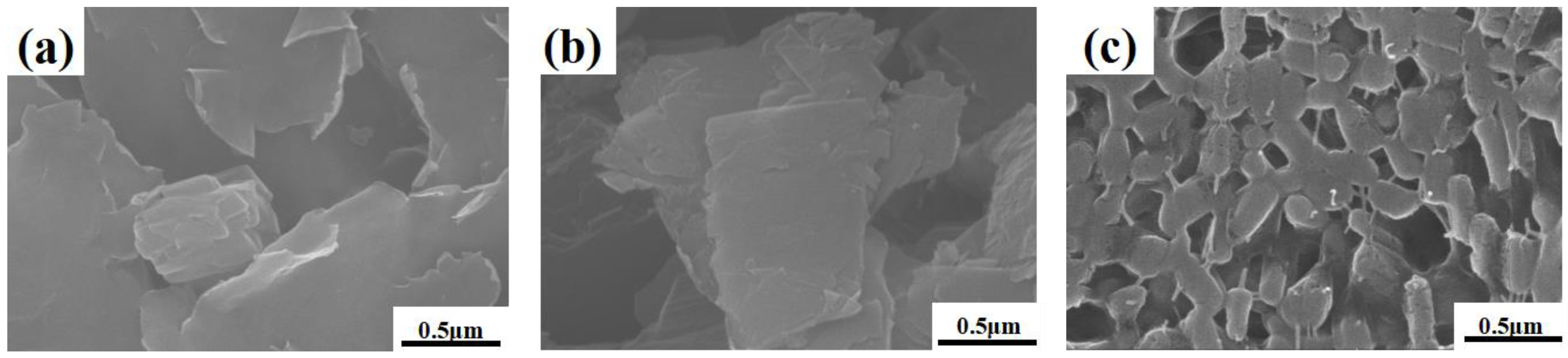
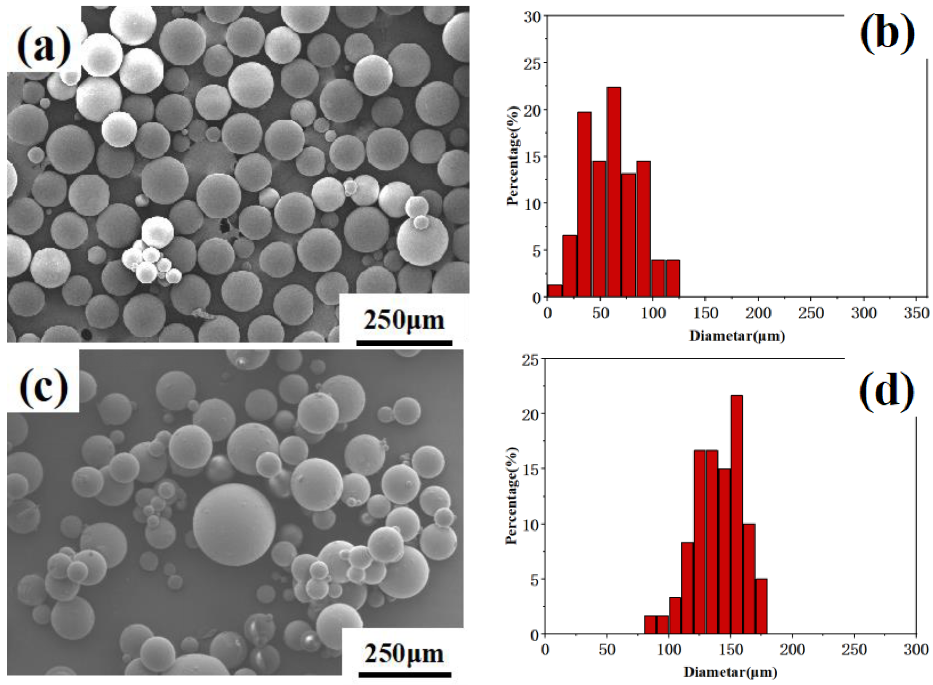
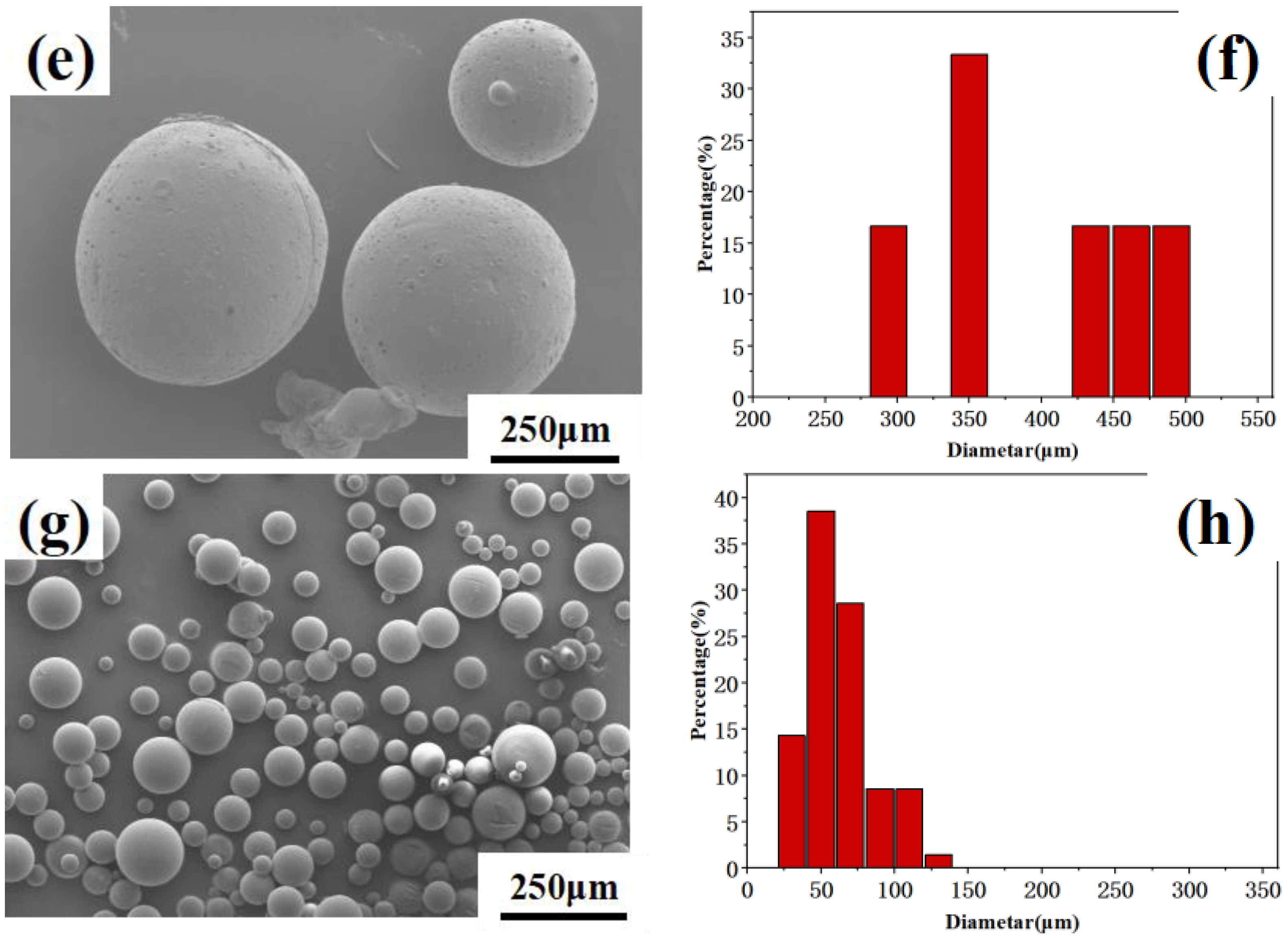
3.1. Morphology Analysis
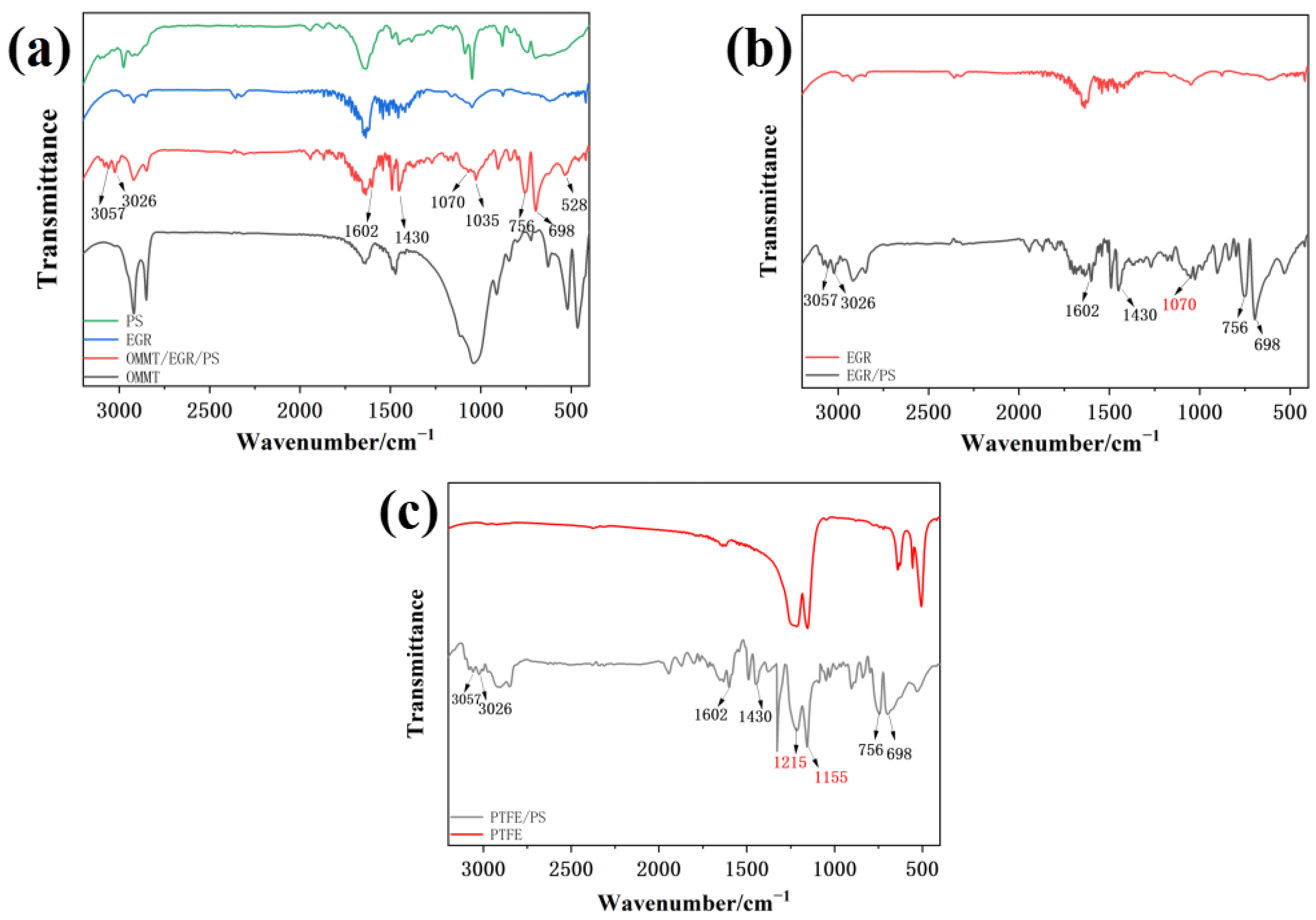
3.2. Infrared Analysis
3.3. Formation Mechanism of Composite Microspheres
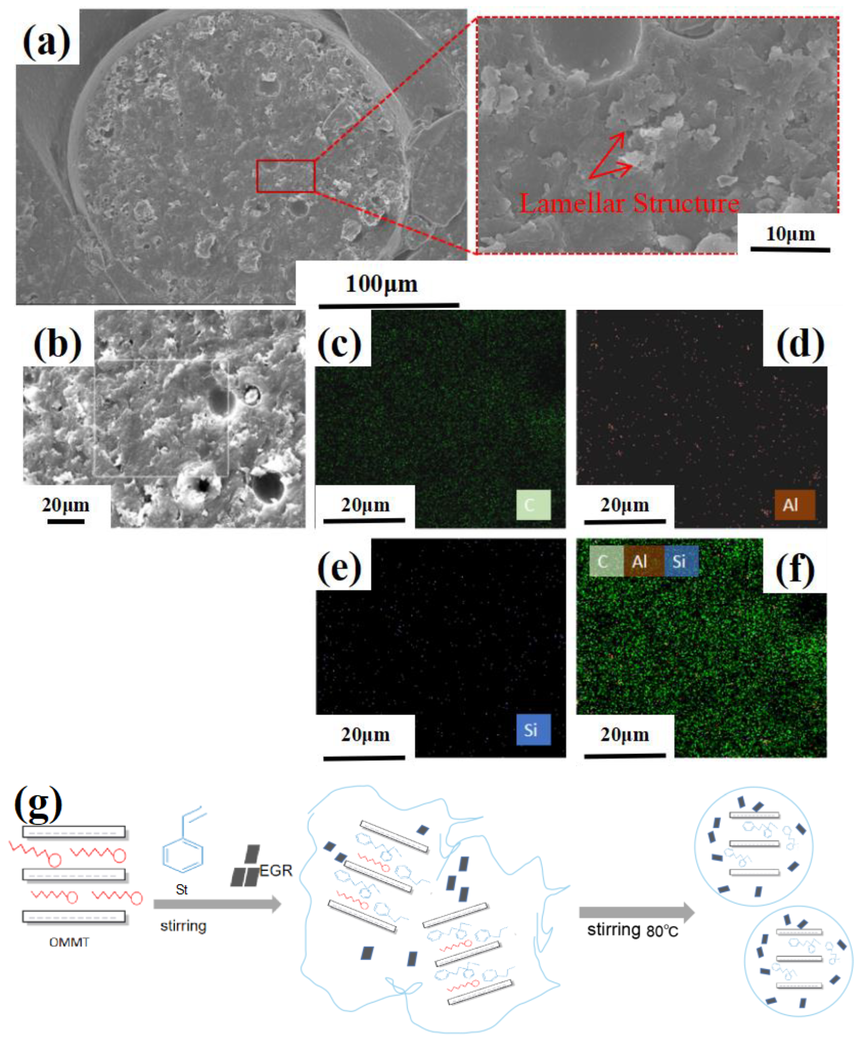
3.3.1. OMMT/EGR/PS
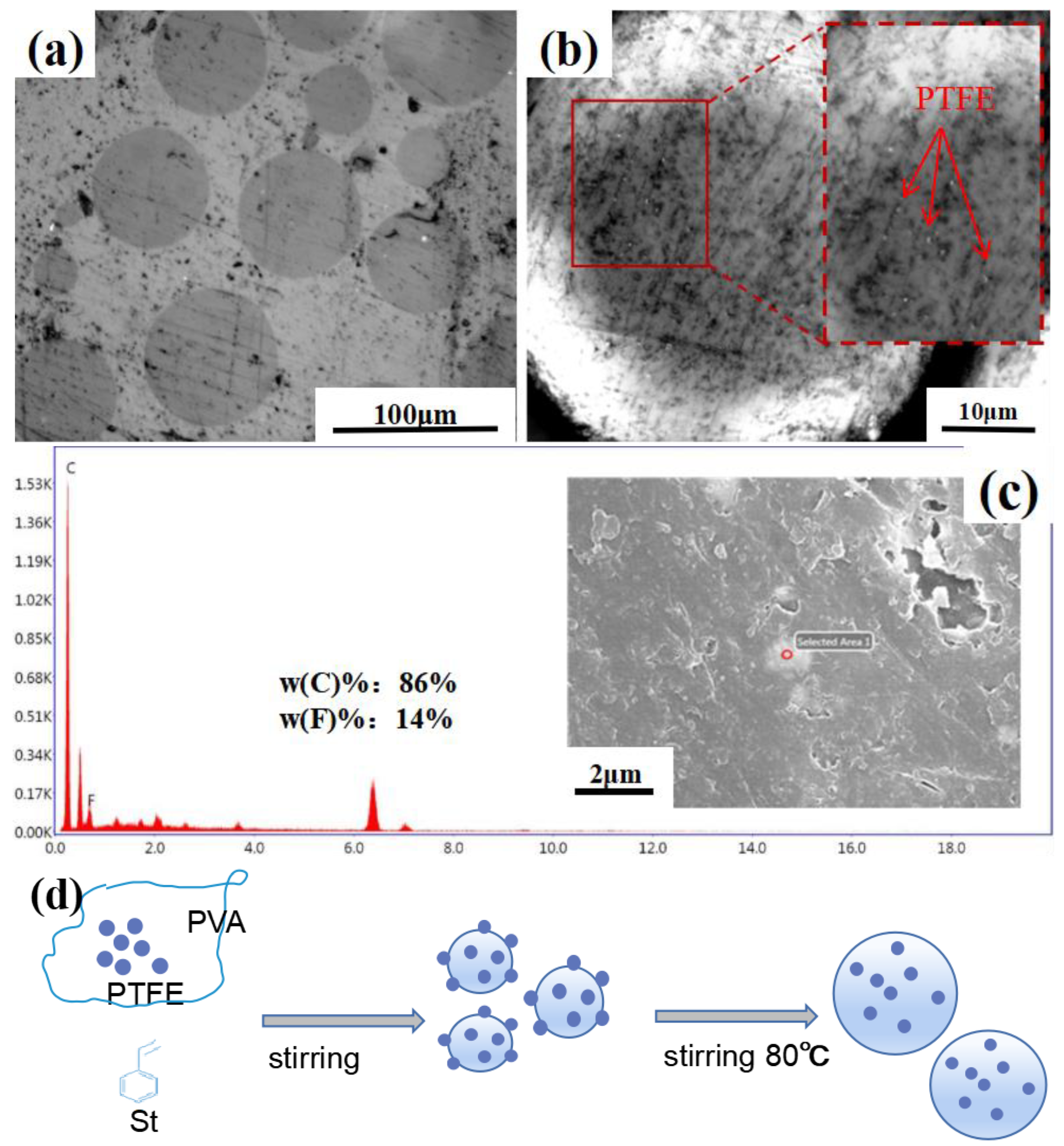
3.3.2. PTFE/PS
3.4. Frictional Properties of Composite Microspheres
3.4.1. Result of Friction and Wear Performance Test
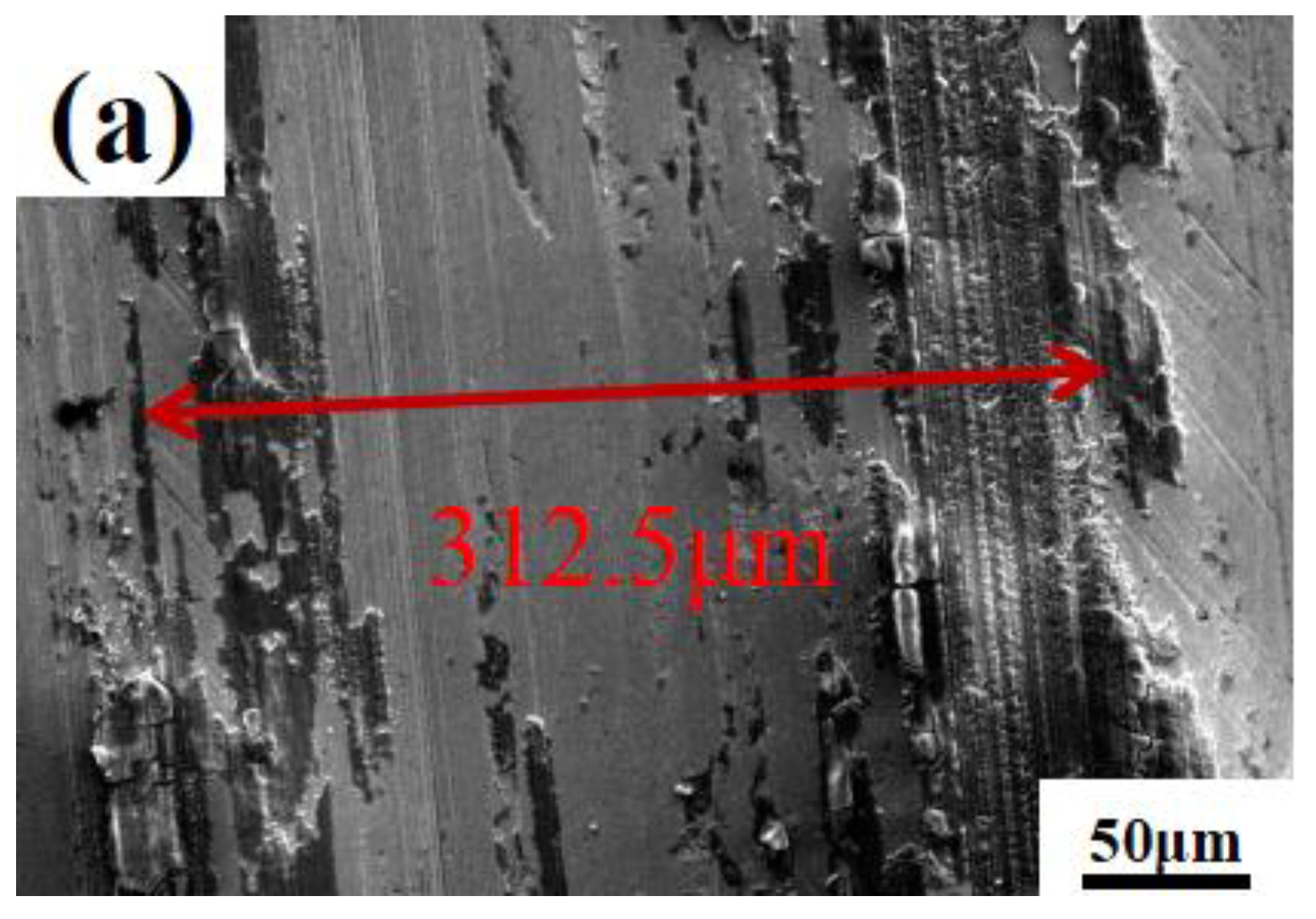
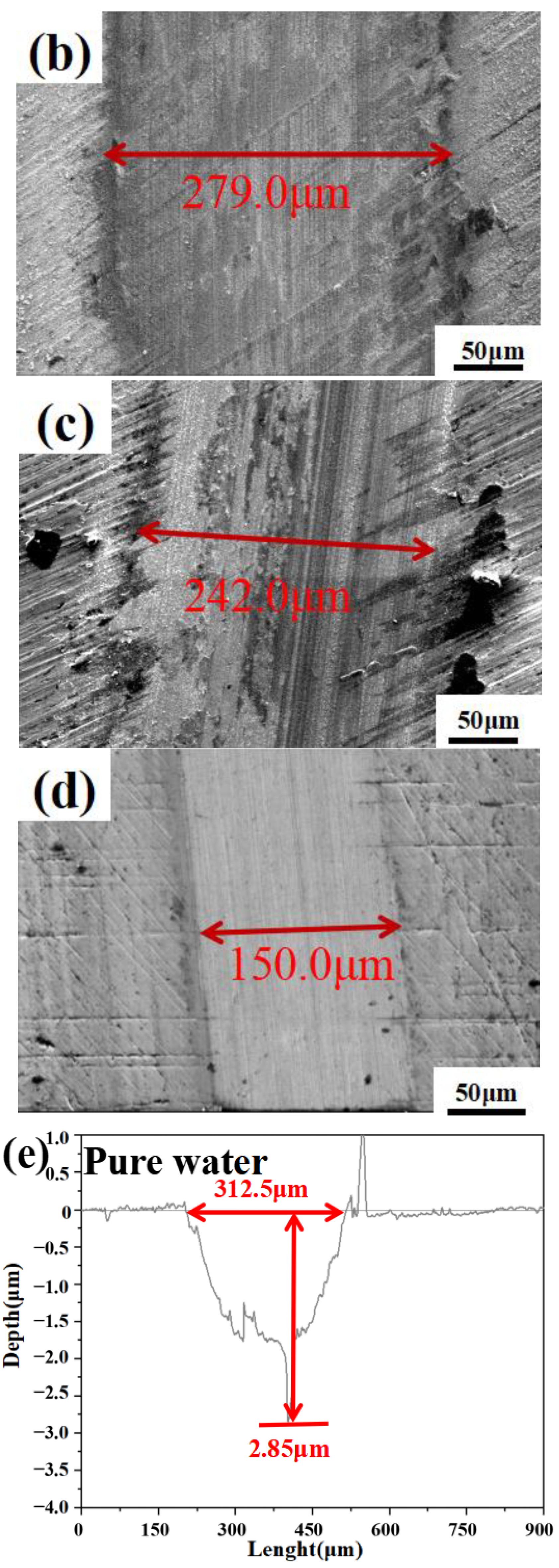
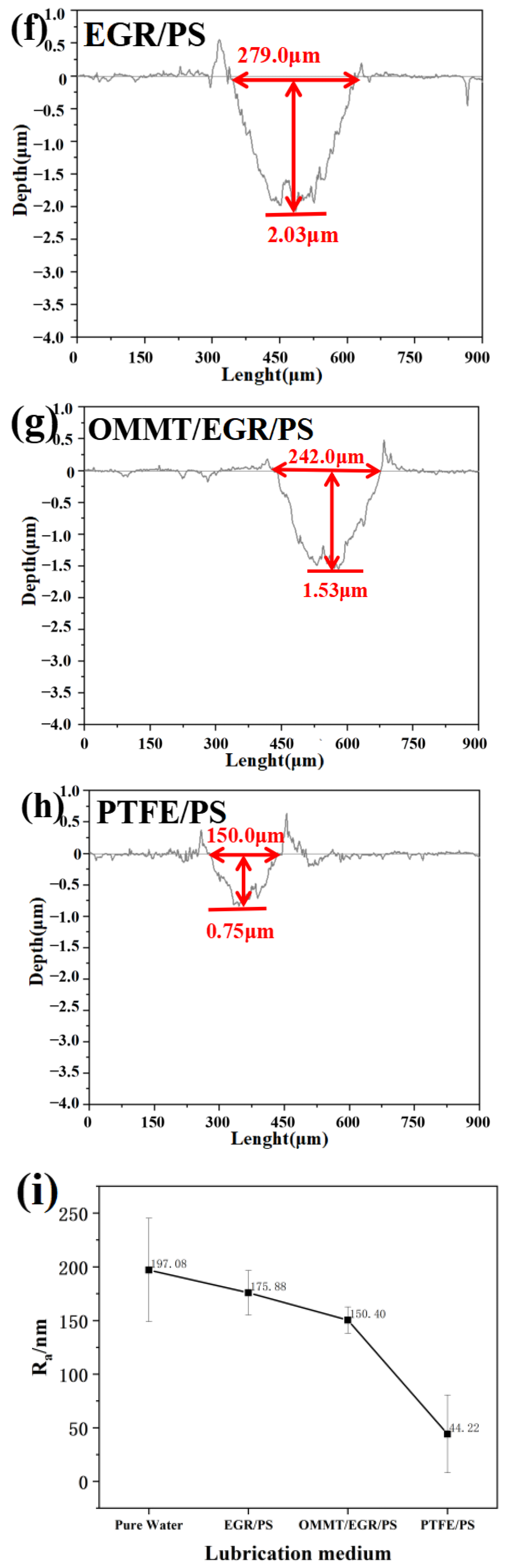
3.4.2. Analysis of Composite Microspheres’ Wear Tracks
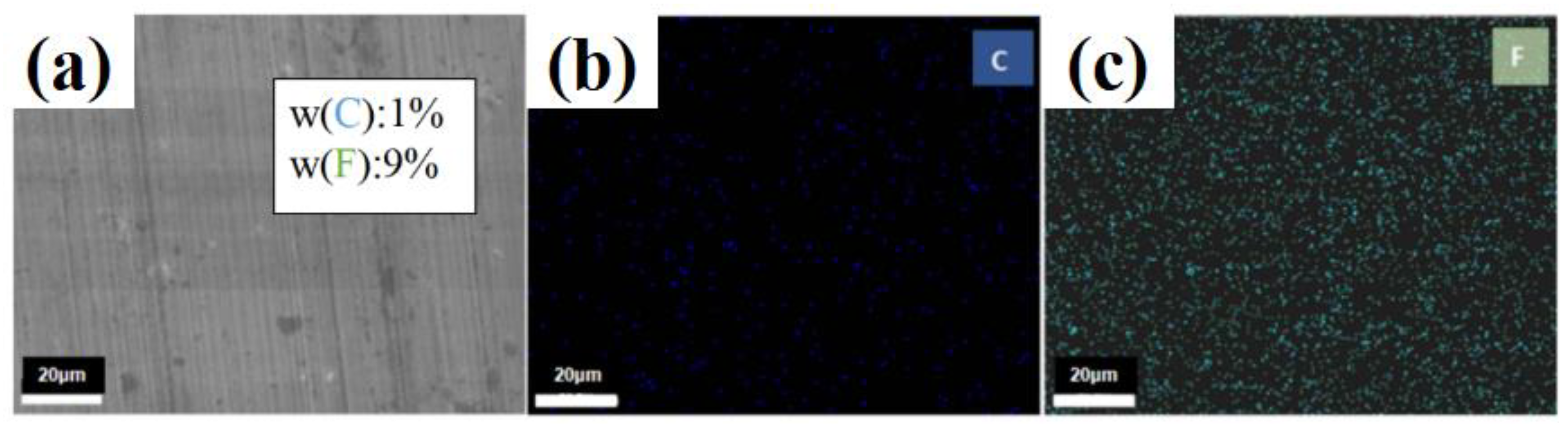
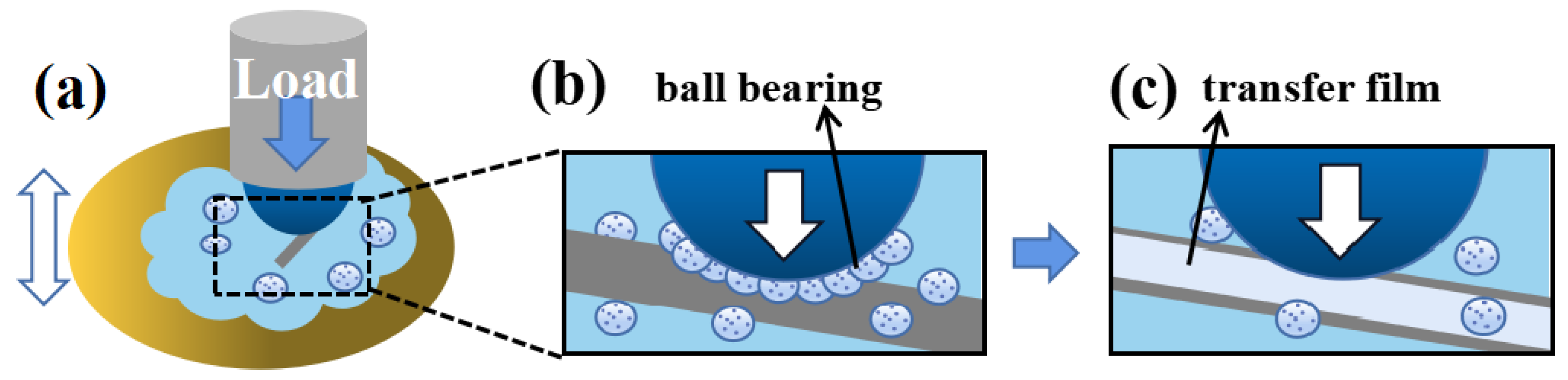
3.4.3. The Lubrication Mechanism of PTFE/PS
4. Conclusions
- EGR/PS, OMMT/EGR/PS, and PTFE/PS were successfully prepared. The particle size of various composite microspheres was counted and compared, and the particles of PTFE/PS were the smallest, averaging 49 μm. The experimental operation of composite microspheres prepared by suspension polymerization was relatively simple. However, the particle size distribution of the prepared microspheres was very broad, and it was not easy to control the particle size of the microspheres in a very accurate range.
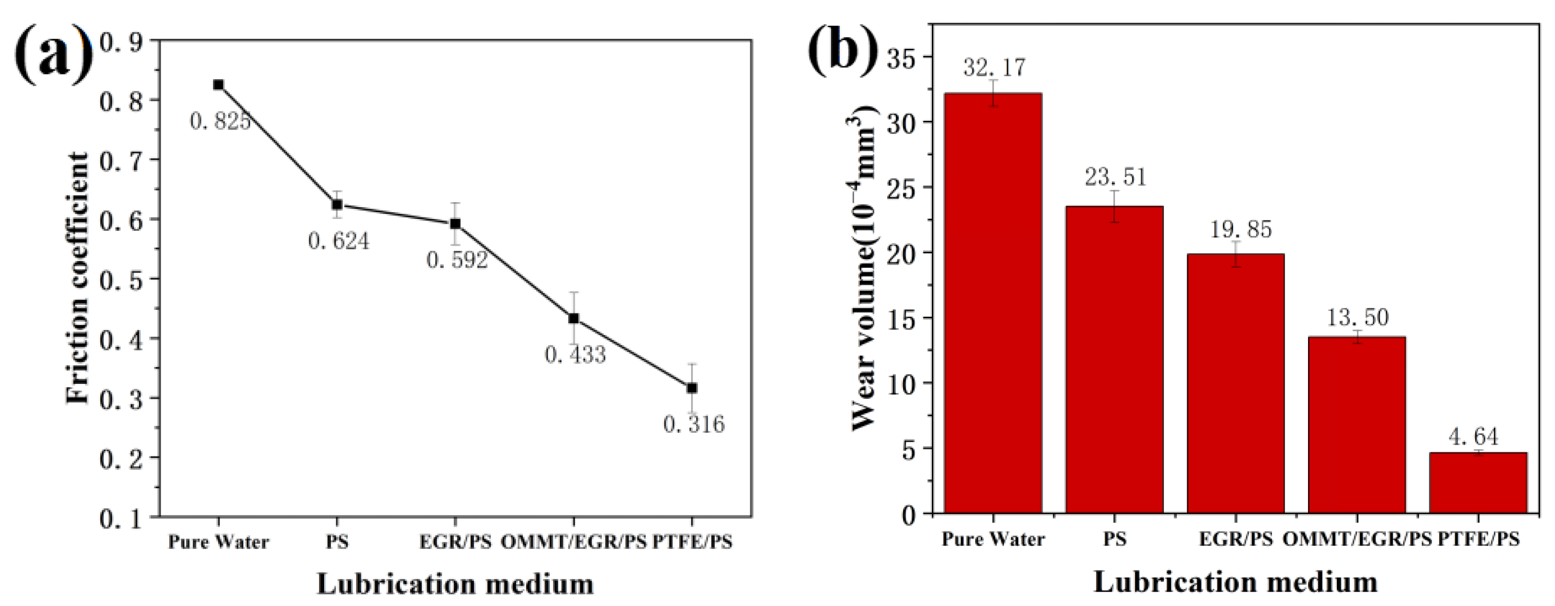
- Compared with pure water, PS, OMMT/EGR/PS, EGR/PS and PTFE/PS all improved the lubrication and wear resistance. PTFE/PS has the best lubricating and anti-wear properties, which can effectively reduce the friction coefficient and reduce the wear volume. Under a load of 10 N, the friction coefficient of PTFE/PS was about 62% lower than that of pure water, and the wear volume was 86% lower than that of pure water.
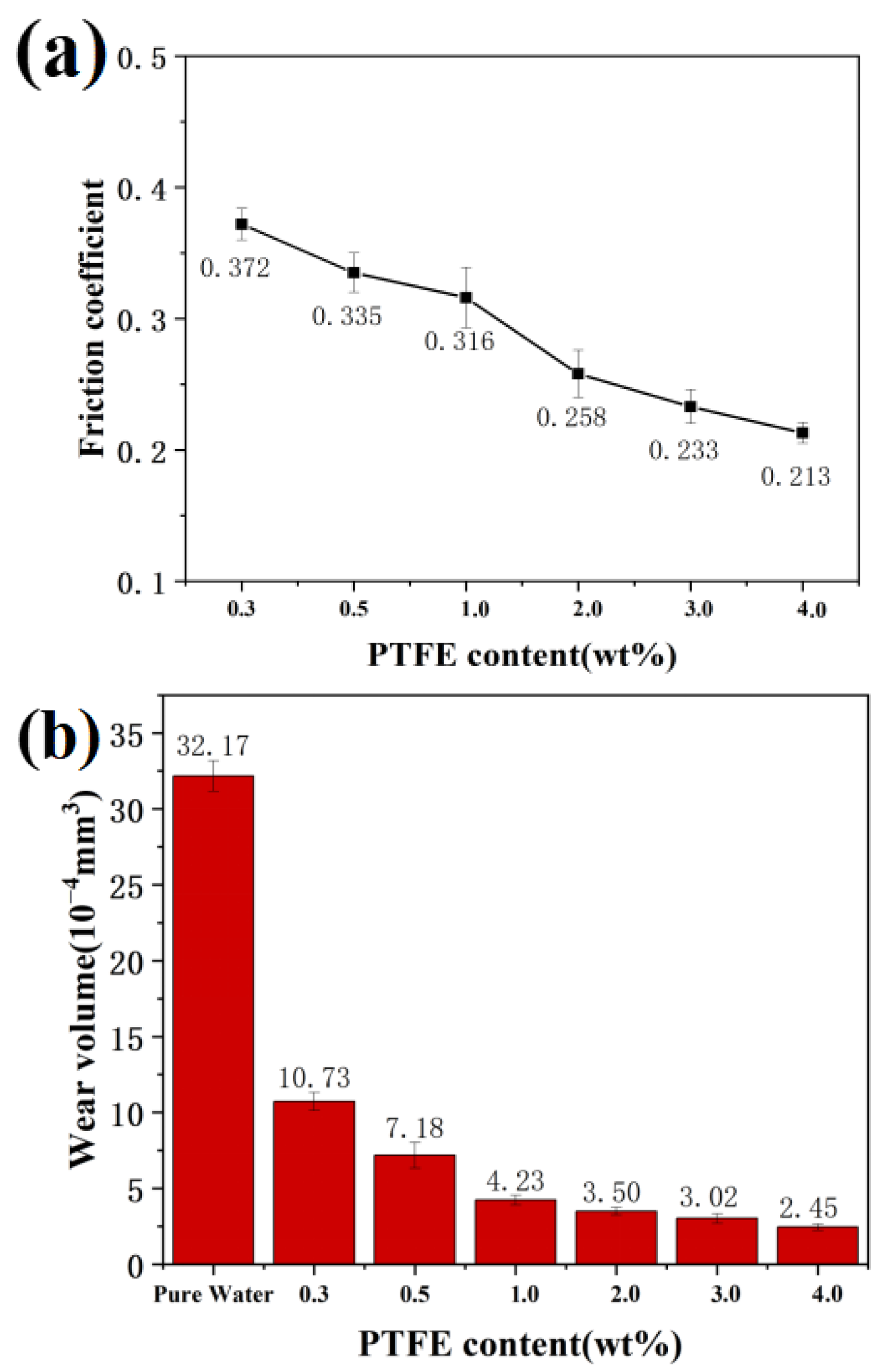
- Increasing the PTFE content can improve the lubricating properties of PTFE/PS. PTFE/PS with 4.0 wt% PTFE addition can reduce the friction coefficient from 0.825 to 0.213, which is nearly 74% lower than that of pure water, and the wear volume of PTFE/PS with 4.0 wt% PTFE is 92.4% lower than that of pure water.
- The spherical structure of PTFE/PS as a ball bearing transforms the sliding friction into rolling friction, and a low shear transfer film composed of PTFE is formed on the wear surface. The combination of rolling friction and low shear transfer film results in excellent lubrication performance of PTFE/PS.
Author Contributions
Funding
Institutional Review Board Statement
Informed Consent Statement
Data Availability Statement
Conflicts of Interest
References
- Shi, S.C. Tribological Performance of Green Lubricant Enhanced by Sulfidation IF-MoS2. Materials 2016, 9, 856. [Google Scholar] [CrossRef] [PubMed] [Green Version]
- Zhao, X.; Li, D.; Zhu, H.; Ma, J.; An, Y. Advanced developments in environmentally friendly lubricants for water-based drilling fluid: A review. RSC Adv. 2022, 12, 22853–22868. [Google Scholar] [CrossRef] [PubMed]
- Nguyen, H.T.; Chung, K.-H. Assessment of tribological properties of Ti3C2 as a water-based lubricant additive. Materials 2020, 13, 5545. [Google Scholar] [CrossRef]
- Tang, L.; Zhang, S.; Zhang, X.; Ma, L.; Pu, B. A review of axial vibration tool development and application for friction-reduction in extended reach wells. J. Pet. Sci. Eng. 2021, 199, 108348. [Google Scholar] [CrossRef]
- Scharf, T.W.; Prasad, S.V. Solid lubricants: A review. J. Mater. Sci. 2013, 48, 511–531. [Google Scholar] [CrossRef]
- Wang, Q.; Slaný, M.; Gu, X.; Miao, Z.; Du, W.; Zhang, J.; Gang, C.J.M. Lubricity and rheological properties of highly dispersed graphite in clay-water-based drilling fluids. Materials 2022, 15, 1083. [Google Scholar] [CrossRef]
- Fang, J.; Xuan, Y.; Li, Q. Preparation of polystyrene spheres in different particle sizes and assembly of the PS colloidal crystals. Sci. China Technol. Sci. 2010, 53, 3088–3093. [Google Scholar] [CrossRef]
- Li, Z.; Ma, S.; Zhang, G.; Wang, D.; Zhou, F. Soft/hard-coupled amphiphilic polymer nanospheres for water lubrication. ACS Appl. Mater. Interfaces 2018, 10, 9178–9187. [Google Scholar] [CrossRef]
- Muñoz-Shugulí, C.; Rodríguez, F.J.; Bruna, J.E.; Galotto, M.J.; Sarantópoulos, C.; Perez, M.A.F.; Padula, M. Cetylpyridinium bromide-modified montmorillonite as filler in low density polyethylene nanocomposite films. Appl. Clay Sci. 2019, 168, 203–210. [Google Scholar] [CrossRef]
- Xi, Y.; Frost, R.L.; He, H.; Kloprogge, T.; Bostrom, T. Modification of Wyoming montmorillonite surfaces using a cationic surfactant. Langmuir 2005, 21, 8675–8680. [Google Scholar] [CrossRef]
- Jing, X.; Jiaxin, Y. Tribological performance and mechanism of graphene oxide/polyimide. Tribology 2020, 40, 12–20. [Google Scholar]
- Wu, Y.; Zeng, X.; Ren, T.; de Vries, E.; van der Heide, E. The emulsifying and tribological properties of modified graphene oxide in oil-in-water emulsion. Tribol. Int. 2017, 105, 304–316. [Google Scholar] [CrossRef]
- Qu, M.; Yao, Y.; He, J.; Ma, X.; Feng, J.; Liu, S.; Hou, L.; Liu, X. Tribological study of polytetrafluoroethylene lubricant additives filled with Cu microparticles or SiO2 nanoparticles. Tribol. Int. 2017, 110, 57–65. [Google Scholar] [CrossRef]
- Sun, W.; Ye, J.; Liu, X.; Liu, K. Atomistic insights into anti-wear mechanisms and protective tribofilm formation in polytetrafluoroethylene composites. J. Tribol. 2022, 144, 091701. [Google Scholar] [CrossRef]
- Yang, Y.; Ma, L.; Wang, H.; Jia, W.; Zhu, J.; Wang, J.; Yang, S. A novel water-based lubricating additive of GO@PTFE: Superior tribological performances from the synergistic effect. Tribol. Int. 2022, 169, 107485. [Google Scholar] [CrossRef]
- Yuan, Y.; Lin, H.; Yu, D.; Yin, Y.; Tang, B.; Li, E.; Zhang, S. Effects of perfluorooctyltriethoxysilane coupling agent on the properties of silica filled PTFE composites. J. Mater. Sci. Mater. Electron. 2017, 28, 8810–8817. [Google Scholar] [CrossRef]
- Randhawa, K.S.; Patel, A.D. A review on tribo-mechanical properties of micro- and nanoparticulate-filled nylon composites. J. Polym. Eng. 2021, 41, 339–355. [Google Scholar] [CrossRef]
- Sorrentino, A.; Altavilla, C.; Merola, M.; Senatore, A.; Ciambelli, P.; Iannace, S. Ciambelli, Nanosheets of MoS2-oleylamine as hybrid filler for self-lubricating polymer composites: Thermal, tribological, and mechanical properties. Polym. Compos. 2015, 36, 1124–1134. [Google Scholar] [CrossRef]
- Sivudu, K.S.; Thomas, S.; Shailaja, D. Synthesis and characterization of poly (4vp-co-dvb)/montmorillonite nanocomposites by in situ intercalative polymerization. Appl. Clay Sci. 2007, 37, 185–192. [Google Scholar] [CrossRef]
- Guan, J.; Liu, D.; Wang, Y.; Feng, B.; Xu, X. Tribological Properties of Nanofluid Prepared by Composite of Multi-Walled Carbon Nanotube and Oleic Acid. Tribology 2020, 40, 290–299. [Google Scholar]
- Giannakas, A.; Spanos, C.; Kourkoumelis, N.; Vaimakis, T.; Ladavos, A. Preparation, characterization and water barrier properties of PS/organo-montmorillonite nanocomposites. Eur. Polym. J. 2008, 44, 3915–3921. [Google Scholar] [CrossRef]
- Yu, C.; Ke, Y.; Hu, X.; Zhao, Y.; Deng, Q.; Lu, S. Effect of bifunctional montmorillonite on the thermal and tribological properties of polystyrene/montmorillonite nanocomposites. Polymers 2019, 11, 834. [Google Scholar] [CrossRef] [PubMed] [Green Version]
- Yang, Y.; Jia, W.; Ma, L.; Zhu, J.; Wang, H.; Hou, K.; Wang, J.; Yang, S. A feasible construction strategy of GO-based hetero-film with long service life at multi-environments: Effective friction transfer application. Tribol. Int. 2022, 168, 107455. [Google Scholar] [CrossRef]
- Han, T.; Zhang, S.; Zhang, C. Unlocking the secrets behind liquid superlubricity:A state-ofthe-art review on phenomena and mechanisms. Firction 2022, 10, 29. [Google Scholar]
- Yan, S.; Yang, Y.; Song, L.; Qi, X.; Zuo, Z.; Xue, Y. Tribological property of 3-aminopropyltriethoxysilane-graphite oxide nanosheets reinforced polyethersulfone composite under drying sliding condition. Tribol. Int. 2016, 103, 316–330. [Google Scholar] [CrossRef]


| PTFE Content/wt% | Stirring Speed/rpm | PVA Potency | Average Particle Size/μm | Friction Coefficient |
|---|---|---|---|---|
| 0.3 | 280 | 0.5% | 74.35 | 0.412 |
| 0.3 | 380 | 1.5% | 59.85 | 0.395 |
| 0.3 | 500 | 2.0% | 49.00 | 0.372 |
| 0.5 | 500 | 2.0% | 47.82 | 0.335 |
Disclaimer/Publisher’s Note: The statements, opinions and data contained in all publications are solely those of the individual author(s) and contributor(s) and not of MDPI and/or the editor(s). MDPI and/or the editor(s) disclaim responsibility for any injury to people or property resulting from any ideas, methods, instructions or products referred to in the content. |
© 2023 by the authors. Licensee MDPI, Basel, Switzerland. This article is an open access article distributed under the terms and conditions of the Creative Commons Attribution (CC BY) license (https://creativecommons.org/licenses/by/4.0/).
Share and Cite
Zeng, W.; Huang, W.; Guo, B.; Sun, Y.; Shen, H. Preparation and Lubricating Properties of Polystyrene Composite Microspheres. Materials 2023, 16, 3071. https://doi.org/10.3390/ma16083071
Zeng W, Huang W, Guo B, Sun Y, Shen H. Preparation and Lubricating Properties of Polystyrene Composite Microspheres. Materials. 2023; 16(8):3071. https://doi.org/10.3390/ma16083071
Chicago/Turabian StyleZeng, Wen, Weiqing Huang, Bing Guo, Yang Sun, and Hangyan Shen. 2023. "Preparation and Lubricating Properties of Polystyrene Composite Microspheres" Materials 16, no. 8: 3071. https://doi.org/10.3390/ma16083071