


Assessment of Five Concrete Types as Candidate Shielding Materials for a Compact Radiation Source Based on the IECF

Abstract
:1. Introduction
2. Materials and Methods
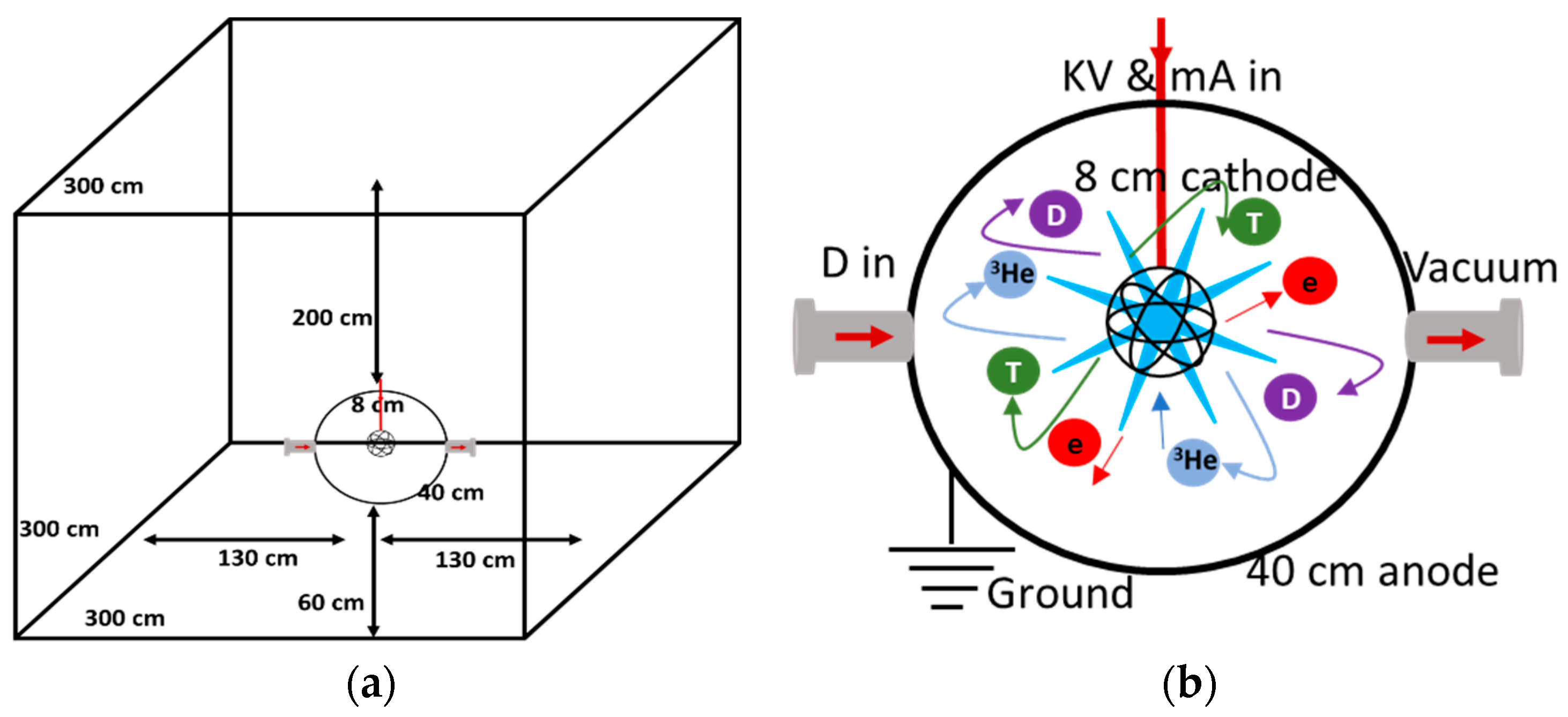
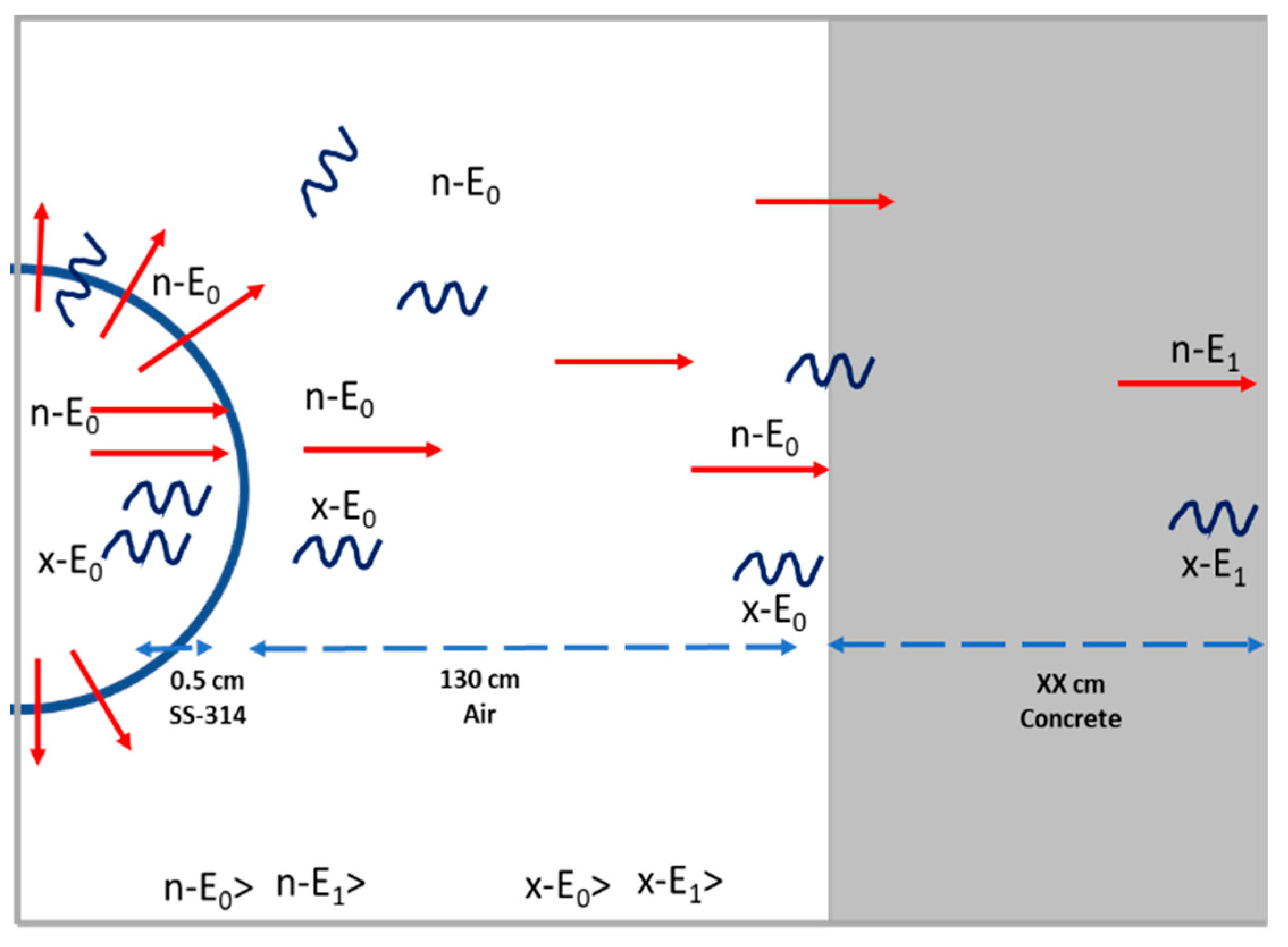
2.1. Radiation Source and the Facility Layout
2.2. Shielding Materials
2.3. Calculation Model
2.3.1. Neutron Attenuation
2.3.2. Photons Attenuation
2.3.3. Methodology
3. Results
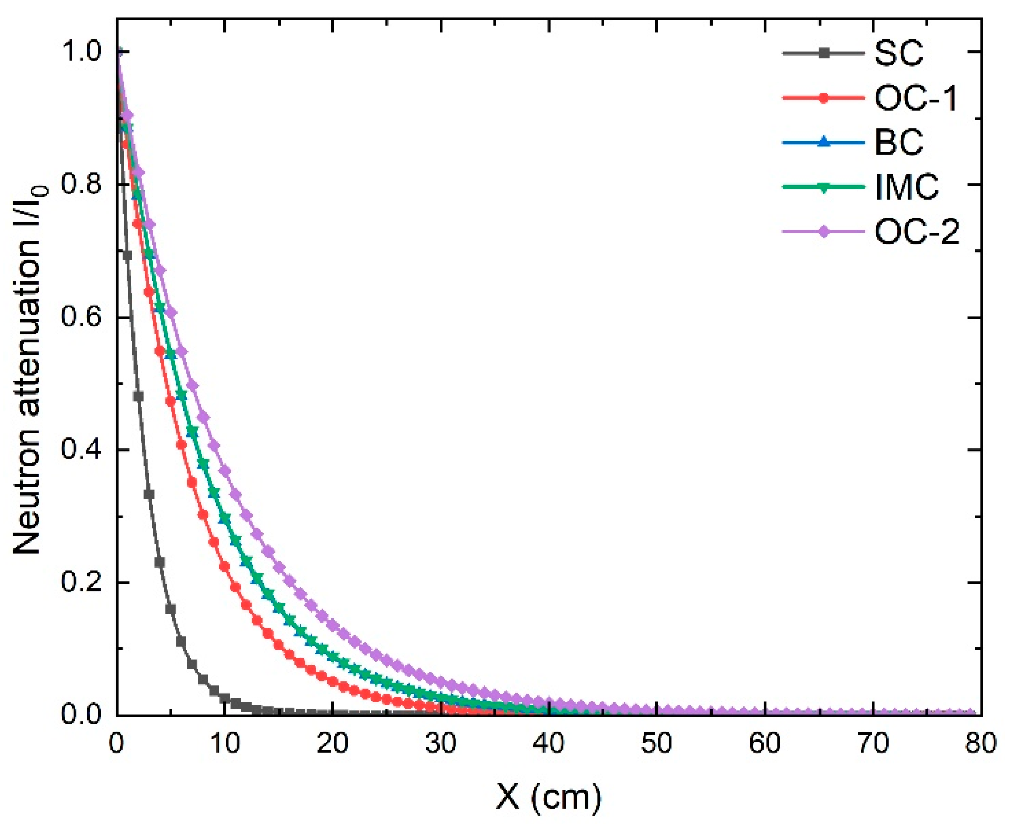
3.1. Neutrons Attenuation
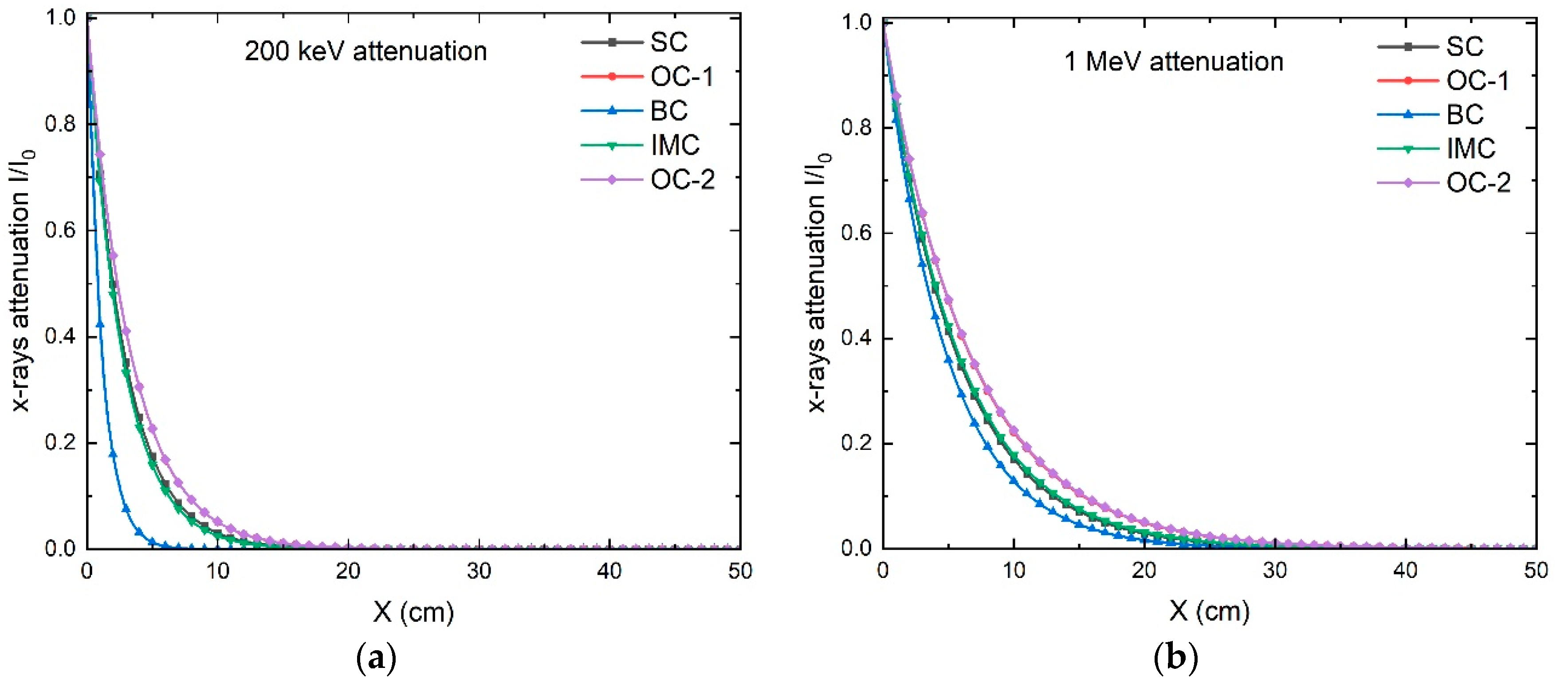
3.2. X-ray Attenuation
4. Conclusions
Author Contributions
Funding
Institutional Review Board Statement
Informed Consent Statement
Data Availability Statement
Acknowledgments
Conflicts of Interest
References
- Chadwick, J. Possible Existence of Neutron. Nature 1932, 129, 312. [Google Scholar] [CrossRef]
- El Abd, A.; Mesbah, G.; Mohammed, N.M.A.; Ellithi, A. A Simple Method for Determining the Effective Removal Cross Section for Fast Neutrons. J. Radiat. Nucl. Appl. 2017, 2, 53–58. [Google Scholar] [CrossRef]
- Aloraini, D.A.; Sayyed, M.I.; Jecong, J.F.M.; Kumar, A.; Elbashir, B.O.; Almuqrin, A.A.H.; Yasmin, S. Structural and Gamma Ray Shielding Behavior of Dual Heavy Metal Oxide Doped Magnesium Sodium Borate Glasses. Optik 2022, 268, 169771. [Google Scholar] [CrossRef]
- Mostafa, A.M.A.; Issa, S.A.M.; Sayyed, M.I. Gamma Ray Shielding Properties of PbO-B2O3-P2O5 Doped with WO3. J. Alloys Compd. 2017, 708, 294–300. [Google Scholar] [CrossRef]
- Coleman, A.C.; Yukihara, E.G. On the Validity and Accuracy of the Initial Rise, Method Investigated Using Realistically Simulated Thermoluminescence Curves. Radiat. Meas. 2018, 117, 70–79. [Google Scholar] [CrossRef]
- Bashter, I.I. Calculation of Radiation Attenuation Coefficients for Shielding Concretes. Ann. Nucl. Energy 1997, 24, 1389–1401. [Google Scholar] [CrossRef]
- Aloraini, D.A.; Sayyed, M.I.; Almuqrin, A.A.H.; Kumar, A.; Khazaalah, T.H.; Yasmin, S.; Khandaker, M.U.; Baki, S.O. Preparation, Radiation Shielding and Mechanical Characterization of PbO–TeO2–MgO–Na2O–B2O3 Glasses. Radiat. Phys. Chem. 2022, 198, 110254. [Google Scholar] [CrossRef]
- Lakshminarayana, G.; Kumar, A.; Tekin, H.O.; Issa, S.A.M.; Al-Buriahi, M.S.; Dong, M.G.; Lee, D.E.; Yoon, J.; Park, T. In-Depth Survey of Nuclear Radiation Attenuation Efficacies for High Density Bismuth Lead Borate Glass System. Results Phys. 2021, 23, 104030. [Google Scholar] [CrossRef]
- Kaçal, M.R.; Akman, F.; Sayyed, M.I. Evaluation of Gamma-Ray and Neutron Attenuation Properties of Some Polymers. Nucl. Eng. Technol. 2019, 51, 818–824. [Google Scholar] [CrossRef]
- Hassan, H.E.; Badran, H.M.; Aydarous, A.; Sharshar, T. Studying the Effect of Nano Lead Compounds Additives on the Concrete Shielding Properties for γ-Rays. Nucl. Instrum. Methods Phys. Res. Sect. B Beam Interact. Mater. Atoms 2015, 360, 81–89. [Google Scholar] [CrossRef]
- Abdullah Aloraini, D.; Sayyed, M.I.; Kumar, A.; Yasmin, S.; Almuqrin, A.H.; Tishkevich, D.I.; Trukhanov, A.V. Studies of Physical, Optical, and Radiation Shielding Properties of Bi2O3-TeO2-MgO-Na2O-B2O3 Glass System. Optik (Stuttg) 2022, 268, 169680. [Google Scholar] [CrossRef]
- El-Samrah, M.G.; Abreu Zamora, M.A.; Novog, D.R.; Chidiac, S.E. Radiation Shielding Properties of Modified Concrete Mixes and Their Suitability in Dry Storage Cask. Prog. Nucl. Energy 2022, 148, 104195. [Google Scholar] [CrossRef]
- Alharshan, G.A.; Alrowaili, Z.A.; Mahmoud, Z.M.M.; Olarinoye, I.O.; Al-Buriahi, M.S. Effect of Nb2O5 Inclusion on the Radiation Shielding Efficiency of TeO2–ZnO–LiF–NaF Glass System. Radiat. Phys. Chem. 2022, 196, 97–101. [Google Scholar] [CrossRef]
- Hadad, K.; Majidi, H.; Sarshough, S. Enhanced Radiation Shielding with Galena Concrete. Nucl. Technol. Radiat. Prot. 2015, 30, 70–74. [Google Scholar] [CrossRef]
- El-Khayatt, A.M.M.; El-Sayed Abdo, A. MERCSF-N: A Program for the Calculation of Fast Neutron Removal Cross Sections in Composite Shields. Ann. Nucl. Energy 2009, 36, 832–836. [Google Scholar] [CrossRef]
- Waly, E.-S.A.; Bourham, M.A. Comparative Study of Different Concrete Composition as Gamma-Ray Shielding Materials. Ann. Nucl. Energy 2015, 85, 306–310. [Google Scholar] [CrossRef]
- Gurler, O.; Akar Tarim, U. An Investigation on Determination of Attenuation Coefficients for Gamma-Rays by Monte Carlo Method. J. Radioanal. Nucl. Chem. 2012, 293, 397–401. [Google Scholar] [CrossRef]
- Hirsch, R.L. Inertial-Electrostatic Confinement of Ionized Fusion Gases. J. Appl. Phys. 1967, 38, 4522–4534. [Google Scholar] [CrossRef]
- Bakr, M.; Masuda, K.; Yoshida, M. Development of a Portable Neutron Generator Based on Inertial Electrostatic Confinement D-D Fusion Reaction. In Proceedings of the AIP Conference Proceedings; American Institute of Physics Inc.: College Park, MA, USA, 2019; Volume 2160, p. 030004. [Google Scholar]
- Bakr, M.; Mukai, K.; Masuda, K.; Yagi, J.; Konishi, S. Characterization of an Ultra-Compact Neutron Source Based on an IEC Fusion Device and Its Prospective Applications in Radiography. Fusion Eng. Des. 2021, 167, 112346. [Google Scholar] [CrossRef]
- Masuda, K.; Kashima, R.; Bakr, M.A. Potential Profile Measurements Inside a Gridded Cathode at High Potential in a Spherical Inertial Electrostatic Confinement Device. Fusion Sci. Technol. 2019, 75, 608–613. [Google Scholar] [CrossRef]
- Almuqrin, A.H.; Jecong, J.F.M.; Hila, F.C.; Balderas, C.V.; Sayyed, M.I. Radiation Shielding Properties of Selected Alloys Using EPICS2017 Data Library. Prog. Nucl. Energy 2021, 137, 103748. [Google Scholar] [CrossRef]
- Evans, B.R.; Lian, J.; Ji, W. Evaluation of Shielding Performance for Newly Developed Composite Materials. Ann. Nucl. Energy 2018, 116, 1–9. [Google Scholar] [CrossRef]
- Elmahroug, Y.; Tellili, B.; Souga, C. Determination of Shielding Parameters for Different Types of Resins. Ann. Nucl. Energy 2014, 63, 619–623. [Google Scholar] [CrossRef]
- Dong, M.; Xue, X.; Liu, S.; Yang, H.; Li, Z.; Sayyed, M.I.; Agar, O. Using Iron Concentrate in Liaoning Province, China, to Prepare Material for X-Ray Shielding. J. Clean. Prod. 2019, 210, 653–659. [Google Scholar] [CrossRef]
- Morgan, K.Z. Radiation Shielding and Dosimetry. Nucl. Sci. Eng. 1980, 73, 112. [Google Scholar] [CrossRef]
- Awadallah, M.I.; Imran, M.M.A. Experimental Investigation of γ-Ray Attenuation in Jordanian Building Materials Using HPGe-Spectrometer. J. Environ. Radioact. 2007, 94, 129–136. [Google Scholar] [CrossRef]
- Gerward, L.; Guilbert, N.; Bjorn Jensen, K.; Levring, H. X-Ray Absorption in Matter. Reengineering XCOM. Radiat. Phys. Chem. 2001, 60, 23–24. [Google Scholar] [CrossRef]
- Liu, Y.; Liu, B.; Gu, Y.; Wang, S.; Li, M. Gamma Radiation Shielding Property of Continuous Fiber Reinforced Epoxy Matrix Composite Containing Functional Filler Using Monte Carlo Simulation. Nucl. Mater. Energy 2022, 33, 101246. [Google Scholar] [CrossRef]
- Bakr, M.; Wulfkühler, J.-P.P.; Mukai, K.; Masuda, K.; Tajmar, M.; Konishi, S. Evaluation of 3D Printed Buckyball-Shaped Cathodes of Titanium and Stainless-Steel for IEC Fusion System. Phys. Plasmas 2021, 28, 012706. [Google Scholar] [CrossRef]
- Bakr, M.; Sakabe, T.; Wulfkühler, J.-P.; Mukai, K.; Smith, T.W.; Ogino, O.; Tajmar, M.; Scott, T.; Konishi, S. Influence of electrodes’ geometrical properties on the neutron production rate of a discharge fusion neutron source. Phys. Plasmas 2023, 30, 032701. [Google Scholar] [CrossRef]
- Mukai, K.; Kenjo, S.; Iwamatsu, N.; Bakr, M.; Chikada, T.; Yagi, J.; Konishi, S. Hydrogen Permeation from F82H Wall of Ceramic Breeder Pebble Bed: The Effect of Surface Corrosion. Int. J. Hydrogen Energy 2022, 47, 6154–6163. [Google Scholar] [CrossRef]
- Donovan, D.C.; Boris, D.R.; Kulcinski, G.L.; Santarius, J.F. Fusion Science and Technology Optimization of an IEC Fusion Device to Increase Steady-State D-D Neutron Generation Rates Optimization of an IEC Fusion Device to Increase Steady-State D-D Neutron Generation Rates. Fusion Sci. Technol. 2017, 56, 507–511. [Google Scholar] [CrossRef]
- El-Khayatt, A.M. Calculation of Fast Neutron Removal Cross-Sections for Some Compounds and Materials. Ann. Nucl. Energy 2010, 37, 218–222. [Google Scholar] [CrossRef]
- Issa, S.A.M.; Saddeek, Y.B.; Tekin, H.O.; Sayyed, M.I.; Shaaban, K. Saber Investigations of Radiation Shielding Using Monte Carlo Method and Elastic Properties of PbO-SiO2-B2O3-Na2O Glasses. Curr. Appl. Phys. 2018, 18, 717–727. [Google Scholar] [CrossRef]
- Dong, M.G.; Xue, X.X.; Elmahroug, Y.; Sayyed, M.I.; Zaid, M.H.M. Investigation of Shielding Parameters of Some Boron Containing Resources for Gamma Ray and Fast Neutron. Results Phys. 2019, 13, 102129. [Google Scholar] [CrossRef]
- Schad, J.; Rost, H. Radiation Shielding. Kunststoffe Int. 2013, 103, 15–18. [Google Scholar] [CrossRef]
- Korkut, T.; Gence, O.; Kam, E.; Brostow, W. X-Ray, Gamma, and Neutron Radiation Tests on Epoxy-Ferrochromium Slag Composites by Experiments and Monte Carlo Simulations. Int. J. Polym. Anal. Charact. 2013, 18, 224–231. [Google Scholar] [CrossRef]
- Seltzer, S.M. Calculation of Photon Mass Energy-Transfer and Mass Energy-Absorption Coefficients. Radiat. Res. 1993, 136, 147. [Google Scholar] [CrossRef]
- Korkut, T.; Karabulut, A.; Budak, G.; Aygün, B.; Gencel, O.; Hançerlioğulları, A. Investigation of Neutron Shielding Properties Depending on Number of Boron Atoms for Colemanite, Ulexite and Tincal Ores by Experiments and FLUKA Monte Carlo Simulations. Appl. Radiat. Isot. 2012, 70, 341–345. [Google Scholar] [CrossRef]
- Tellili, B.; Elmahroug, Y.; Souga, C. Investigation on Radiation Shielding Parameters of Cerrobend Alloys. Nucl. Eng. Technol. 2017, 49, 1758–1771. [Google Scholar] [CrossRef]
- El-Khayatt, A.M.; Akkurt, I. Photon Interaction, Energy Absorption and Neutron Removal Cross Section of Concrete Including Marble. Ann. Nucl. Energy 2013, 60, 8–14. [Google Scholar] [CrossRef]
- Oto, B.; Madak, Z.; Kavaz, E.; Yaltay, N. Nuclear Radiation Shielding and Mechanical Properties of Colemanite Mineral Doped Concretes. Radiat. Eff. Defects Solids 2019, 174, 899–914. [Google Scholar] [CrossRef]
- El-Sayed Abdo, A. Calculation of the Cross-Sections for Fast Neutrons and Gamma-Rays in Concrete Shields. Ann. Nucl. Energy 2002, 29, 1977–1988. [Google Scholar] [CrossRef]
- Pagonis, V.; Shannon, C. Improved Experimental Procedure of Separating a Composite Thermoluminescence Glow Curve into Its Components. Radiat. Meas. 2000, 32, 805–812. [Google Scholar] [CrossRef]
- Atasoy, H.; Tarcan, G.; Dökmen, S. Investigation of Turkish Marbles as Shielding Materials. Nucl. Inst. Methods Phys. Res. B 1992, 71, 201–203. [Google Scholar] [CrossRef]
- Sukegawa, A.M.; Anayama, Y.; Okuno, K.; Sakurai, S.; Kaminaga, A. Flexible Heat Resistant Neutron Shielding Resin. J. Nucl. Mater. 2011, 417, 850–853. [Google Scholar] [CrossRef]
- Hubbell, J.H. Photon Mass Attenuation and Energy-Absorption Coefficients. Int. J. Appl. Radiat. Isot. 1982, 33, 1269–1290. [Google Scholar] [CrossRef]
- Içelli, O.; Yalçin, Z.; Okutan, M.; Boncukçuoǧlu, R.; Şen, A. The Determination of the Total Mass Attenuation Coefficients and the Effective Atomic Numbers for Concentrated Colemanite and Emet Colemanite Clay. Ann. Nucl. Energy 2011, 38, 2079–2085. [Google Scholar] [CrossRef]
- Gaikwad, D.K.; Obaid, S.S.; Sayyed, M.I.; Bhosale, R.R.; Awasarmol, V.V.; Kumar, A.; Shirsat, M.D.; Pawar, P.P. Comparative Study of Gamma Ray Shielding Competence of WO3-TeO2-PbO Glass System to Different Glasses and Concretes. Mater. Chem. Phys. 2018, 213, 508–517. [Google Scholar] [CrossRef]
- Levet, A.; Kavaz, E.; Özdemir, Y. An Experimental Study on the Investigation of Nuclear Radiation Shielding Characteristics in Iron-Boron Alloys. J. Alloys Compd. 2020, 819, 152946. [Google Scholar] [CrossRef]
- Mukai, K.; Ogino, Y.; Kobayashi, M.I.; Bakr, M.; Yagi, J.; Ogawa, K.; Isobe, M.; Konishi, S. Evaluation of Tritium Production Rate in a Blanket Mock-up Using a Compact Fusion Neutron Source. Nucl. Fusion 2021, 61, 046034. [Google Scholar] [CrossRef]
- Michalak, M.K.; Fancher, A.N.; Kulcinski, G.L.; Santarius, J.F. Expanding Operational Space in Inertial Electrostatic Confinement D-D Neutron Generators. Fusion Sci. Technol. 2017, 72, 449–454. [Google Scholar] [CrossRef]
- El-Samrah, M.G.; El-Mohandes, A.M.; El-Khayatt, A.M.; Chidiac, S.E. MRCsC: A User-Friendly Software for Predicting Shielding Effectiveness against Fast Neutrons. Radiat. Phys. Chem. 2021, 182, 109356. [Google Scholar] [CrossRef]
- Abo-El-Enein, S.A.; El-Sayed, H.A.; Ali, A.H.; Mohammed, Y.T.; Khater, H.M.; Ouda, A.S. Physico-Mechanical Properties of High-Performance Concrete Using Different Aggregates in Presence of Silica Fume. HBRC J. 2014, 10, 43–48. [Google Scholar] [CrossRef] [Green Version]
- Sigma Periodic Table Browse. Available online: https://www.nndc.bnl.gov/sigma/index.jsp (accessed on 7 January 2023).
- Al-Hamarneh, I.F. Investigation of Gamma-Ray Shielding Effectiveness of Natural Marble Used for External Wall Cladding of Buildings in Riyadh, Saudi Arabia. Results Phys. 2017, 7, 1792–1798. [Google Scholar] [CrossRef]
- Yasaka, P.; Pattanaboonmee, N.; Kim, H.J.J.; Limkitjaroenporn, P.; Kaewkhao, J. Gamma Radiation Shielding and Optical Properties Measurements of Zinc Bismuth Borate Glasses. Ann. Nucl. Energy 2014, 68, 4–9. [Google Scholar] [CrossRef]
- Obaid, S.S.; Sayyed, M.I.I.; Gaikwad, D.K.K.; Pawar, P.P.P. Attenuation Coefficients and Exposure Buildup Factor of Some Rocks for Gamma Ray Shielding Applications. Radiat. Phys. Chem. 2018, 148, 86–94. [Google Scholar] [CrossRef]
- Oto, B.; Gür, A.; Kavaz, E.; Çakır, T.; Yaltay, N. Determination of Gamma and Fast Neutron Shielding Parameters of Magnetite Concretes. Prog. Nucl. Energy 2016, 92, 71–80. [Google Scholar] [CrossRef]
- Tekin, H.O.; Altunsoy, E.E.; Kavaz, E.; Sayyed, M.I.; Agar, O.; Kamislioglu, M. Photon and Neutron Shielding Performance of Boron Phosphate Glasses for Diagnostic Radiology Facilities. Results Phys. 2019, 12, 1457–1464. [Google Scholar] [CrossRef]
- Sayyed, M.I. Investigation of Shielding Parameters for Smart Polymers. Chin. J. Phys. 2016, 54, 408–415. [Google Scholar] [CrossRef]
- Sayyed, M.I. Half Value Layer, Mean Free Path and Exposure Buildup Factor for Tellurite Glasses with Different Oxide Compositions. J. Alloys Compd. 2017, 695, 3191–3197. [Google Scholar] [CrossRef]
- D’Souza, A.N.; Sharmila, K.; Sayyed, M.I.; Somshekarappa, H.M.; Khandaker, M.U.; Bradley, D.A.; Kamath, S.D. Gamma Ray Shielding and Thermoluminescence Investigation of Bismuth Added Heavy Metal Oxide Glasses. Radiat. Phys. Chem. 2021, 188. [Google Scholar] [CrossRef]


| Element Properties | IMC | OC-1 | BC | OC-2 | SC | |||||||
|---|---|---|---|---|---|---|---|---|---|---|---|---|
| S | A | Z | wi | ρi | wi | ρi | wi | ρi | wi | ρi | wi | ρi |
| H | 1 | 1.008 | 0.57 | 0.0157 | 2.21 | 0.0508 | 0.36 | 0.0121 | 0.56 | 0.0132 | 7.20 | 0.1872 |
| C | 6 | 12.011 | 0.08 | 0.0022 | 0.25 | 0.0058 | 0.15 | 0.0039 | ||||
| O | 8 | 15.999 | 37.85 | 1.0523 | 57.75 | 1.3283 | 31.18 | 1.0445 | 49.56 | 1.1647 | 55.6 | 1.4456 |
| Na | 11 | 22.989 | 1.52 | 0.0349 | 1.71 | 0.0402 | ||||||
| Mg | 12 | 24.305 | 3.65 | 0.1014 | 0.13 | 0.0029 | 0.11 | 0.0037 | 0.24 | 0.0056 | 10.20 | 0.2652 |
| Al | 13 | 26.982 | 1.79 | 0.0497 | 2.10 | 0.0483 | 0.42 | 0.0141 | 4.56 | 0.1072 | 2.50 | 0.065 |
| Si | 14 | 28.086 | 4.85 | 0.1349 | 30.56 | 0.7029 | 1.04 | 0.0348 | 31.35 | 0.7367 | 17.55 | 0.4563 |
| P | 15 | 30.974 | 0.01 | 0.0002 | ||||||||
| S | 16 | 32.060 | 0.06 | 0.0016 | 10.78 | 0.3611 | 0.12 | 0.0028 | ||||
| K | 19 | 39.098 | 1.08 | 0.0248 | 1.92 | 0.0451 | 0.08 | 0.0021 | ||||
| Ca | 20 | 40.080 | 8.88 | 0.2469 | 4.39 | 0.1009 | 5.02 | 0.1682 | 8.26 | 0.1941 | 5.64 | 0.1466 |
| Ti | 22 | 47.880 | 12.82 | 0.3563 | ||||||||
| V | 23 | 50.942 | 0.08 | 0.0021 | ||||||||
| Cr | 24 | 51.996 | 0.04 | 0.0010 | ||||||||
| Mn | 25 | 54.938 | 0.30 | 0.0084 | ||||||||
| Fe | 26 | 55.847 | 28.28 | 0.7863 | 0.70 | 0.0161 | 4.75 | 0.1595 | 1.22 | 0.0287 | 1.08 | 0.0281 |
| Ni | 28 | 58.690 | 0.04 | 0.0012 | ||||||||
| Ba | 56 | 137.330 | 46.34 | 1.5524 | ||||||||
| Density (g cm−3) | 2.78 | 2.30 | 3.35 | 2.35 | 2.60 | |||||||
| Elements | IMC | OC-1 | BC | OC-2 | SC |
|---|---|---|---|---|---|
| ∑Ri(cm−1) | |||||
| H | 0.02450 | 0.07932 | 0.01882 | 0.02054 | 0.29213 |
| C | 0.00017 | 0.00046 | 0.00031 | ||
| O | 0.01904 | 0.02404 | 0.01890 | 0.02108 | 0.02616 |
| Na | 0.00302 | 0.00347 | |||
| Mg | 0.00521 | 0.00015 | 0.00019 | 0.00029 | 0.01364 |
| Al | 0.00298 | 0.00290 | 0.00084 | 0.00642 | 0.00390 |
| Si | 0.00620 | 0.03228 | 0.00160 | 0.03384 | 0.02096 |
| P | 0.00001 | ||||
| S | 0.00009 | 0.02091 | 0.00016 | ||
| K | 0.00130 | 0.00237 | 0.00011 | ||
| Ca | 0.01324 | 0.00542 | 0.00902 | 0.01041 | 0.00787 |
| Ti | 0.01288 | ||||
| V | 0.00010 | ||||
| Cr | 0.00005 | ||||
| Mn | 0.00032 | ||||
| Fe | 0.03601 | 0.00074 | 0.00729 | 0.00131 | 0.00129 |
| Ni | 0.00015 | ||||
| Ba | 0.04454 | ||||
| ∑Rt (cm−1) | 0.12095 | 0.14962 | 0.12211 | 0.09989 | 0.36635 |
| Element | µmi (1 MeV) (cm2 g−1) | µmi (0.2 MeV) (cm2 g−1) |
|---|---|---|
| H | 0.12630 | 0.24290 |
| C | 0.06361 | 0.12290 |
| O | 0.06372 | 0.12370 |
| Na | 0.06100 | 0.11990 |
| Mg | 0.06296 | 0.12450 |
| Al | 0.06146 | 0.12230 |
| Si | 0.06361 | 0.12750 |
| P | 0.06182 | 0.12500 |
| S | 0.06373 | 0.13020 |
| K | 0.06216 | 0.13190 |
| Ca | 0.06388 | 0.13760 |
| Ti | 0.05891 | 0.13140 |
| V | 0.05794 | 0.13180 |
| Cr | 0.05930 | 0.13780 |
| Mn | 0.05852 | 0.13910 |
| Fe | 0.05995 | 0.14600 |
| Ni | 0.06160 | 0.11990 |
| Ba | 0.05803 | 0.40450 |
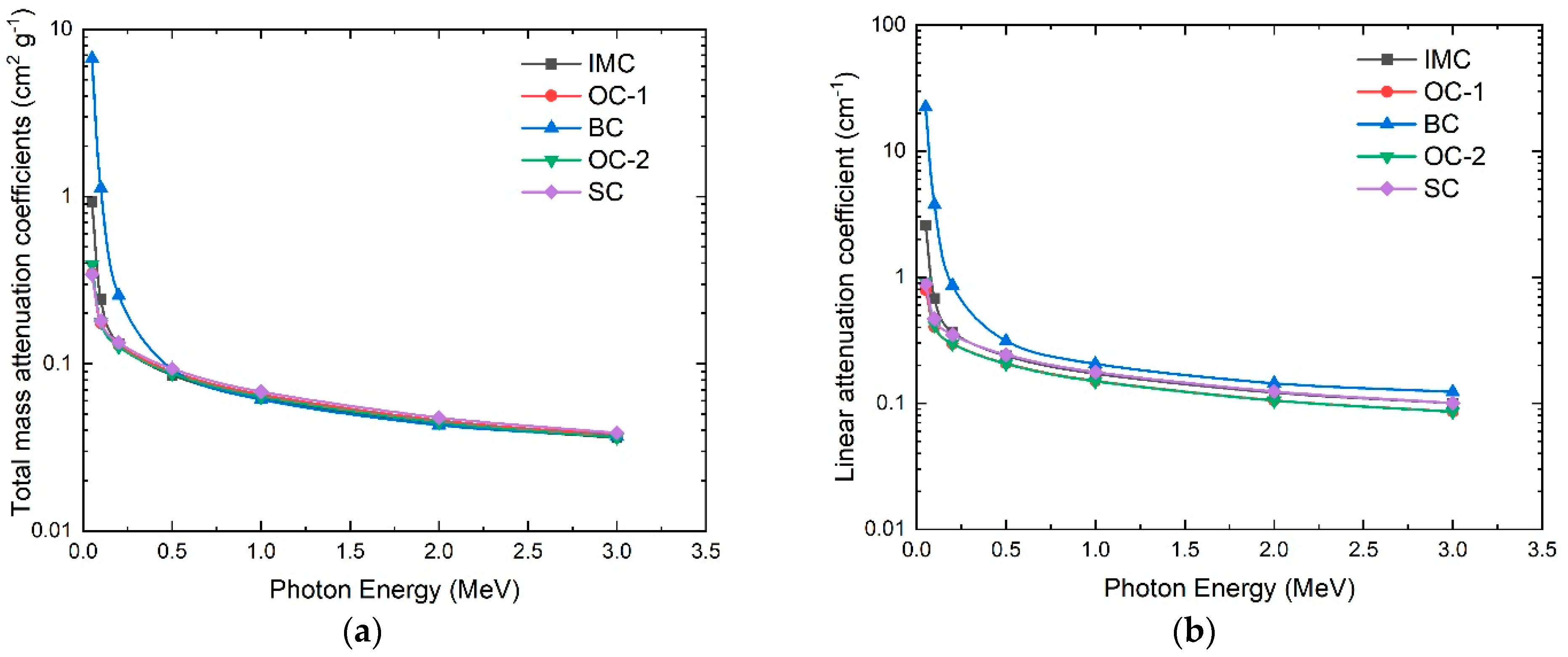
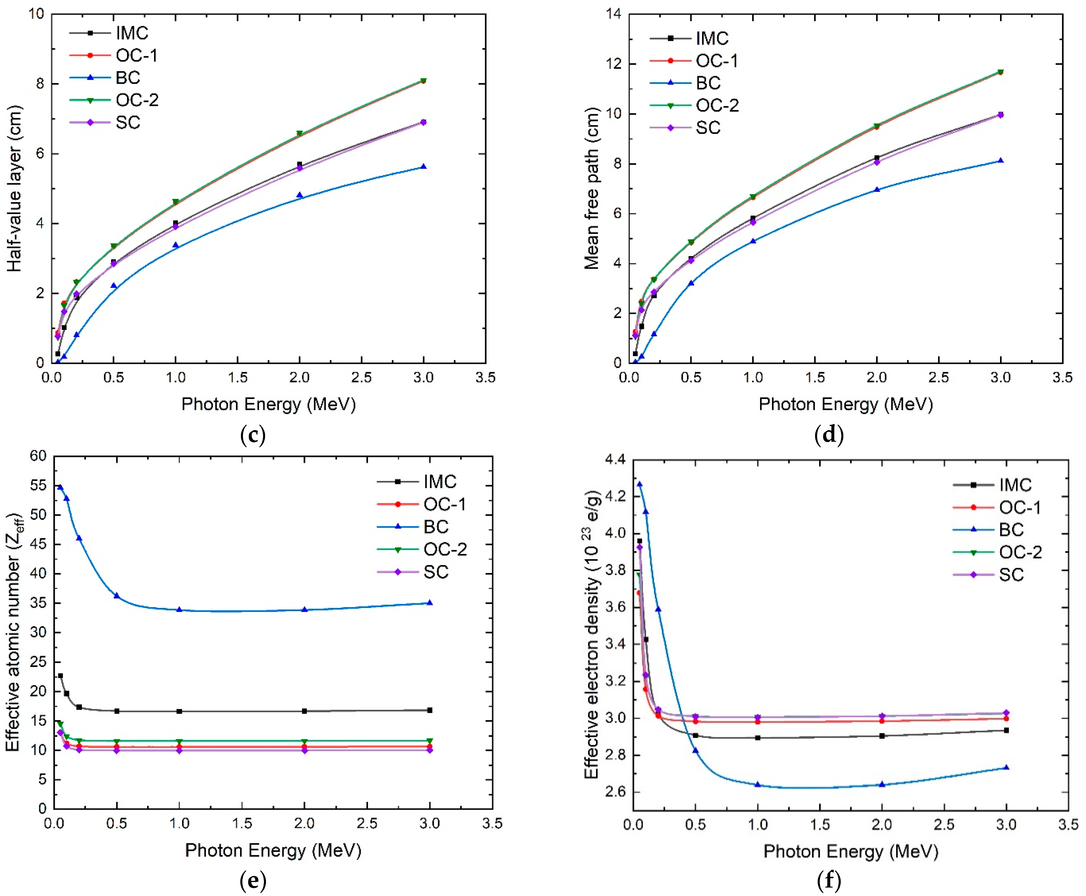
| Concrete Type | Total µmt * (cm2 g−1) | HVL * (cm) | MFP * (cm) | Zeff * | Neff * (1023 e/g) | Total µmt # (cm2 g−1) | HVL # (cm) | MFP # (cm) | Zeff # | Neff # (1023 e/g) |
|---|---|---|---|---|---|---|---|---|---|---|
| IMC | 0.06185 | 4.03013 | 5.81548 | 16.54016 | 2.89570 | 0.13228 | 1.88443 | 2.71924 | 17.35705 | 3.02560 |
| OC-1 | 0.06538 | 4.60831 | 6.64980 | 10.58819 | 2.98000 | 0.12639 | 2.33360 | 3.36738 | 10.70426 | 3.01267 |
| BC | 0.06113 | 3.38418 | 4.88338 | 33.81705 | 2.63872 | 0.25674 | 0.80573 | 3.36738 | 45.99331 | 3.23884 |
| OC-2 | 0.06350 | 4.64376 | 6.70095 | 11.58687 | 3.00708 | 0.12912 | 2.33304 | 3.36658 | 11.74539 | 3.04822 |
| SC | 0.06804 | 3.91742 | 5.65284 | 9.964079 | 3.00542 | 0.13403 | 1.98871 | 2.86971 | 10.10404 | 3.04764 |
Disclaimer/Publisher’s Note: The statements, opinions and data contained in all publications are solely those of the individual author(s) and contributor(s) and not of MDPI and/or the editor(s). MDPI and/or the editor(s) disclaim responsibility for any injury to people or property resulting from any ideas, methods, instructions or products referred to in the content. |
© 2023 by the authors. Licensee MDPI, Basel, Switzerland. This article is an open access article distributed under the terms and conditions of the Creative Commons Attribution (CC BY) license (https://creativecommons.org/licenses/by/4.0/).
Share and Cite
Ahmed, R.; Saad Hassan, G.; Scott, T.; Bakr, M. Assessment of Five Concrete Types as Candidate Shielding Materials for a Compact Radiation Source Based on the IECF. Materials 2023, 16, 2845. https://doi.org/10.3390/ma16072845
Ahmed R, Saad Hassan G, Scott T, Bakr M. Assessment of Five Concrete Types as Candidate Shielding Materials for a Compact Radiation Source Based on the IECF. Materials. 2023; 16(7):2845. https://doi.org/10.3390/ma16072845
Chicago/Turabian StyleAhmed, Rawheya, Galal Saad Hassan, Thomas Scott, and Mahmoud Bakr. 2023. "Assessment of Five Concrete Types as Candidate Shielding Materials for a Compact Radiation Source Based on the IECF" Materials 16, no. 7: 2845. https://doi.org/10.3390/ma16072845