
Mechanical Modelling of the Strength and Stiffness of Circular Hollow Section Tube under Localised Transverse Compression and Tension
 , ,
, ,
Abstract
:1. Introduction
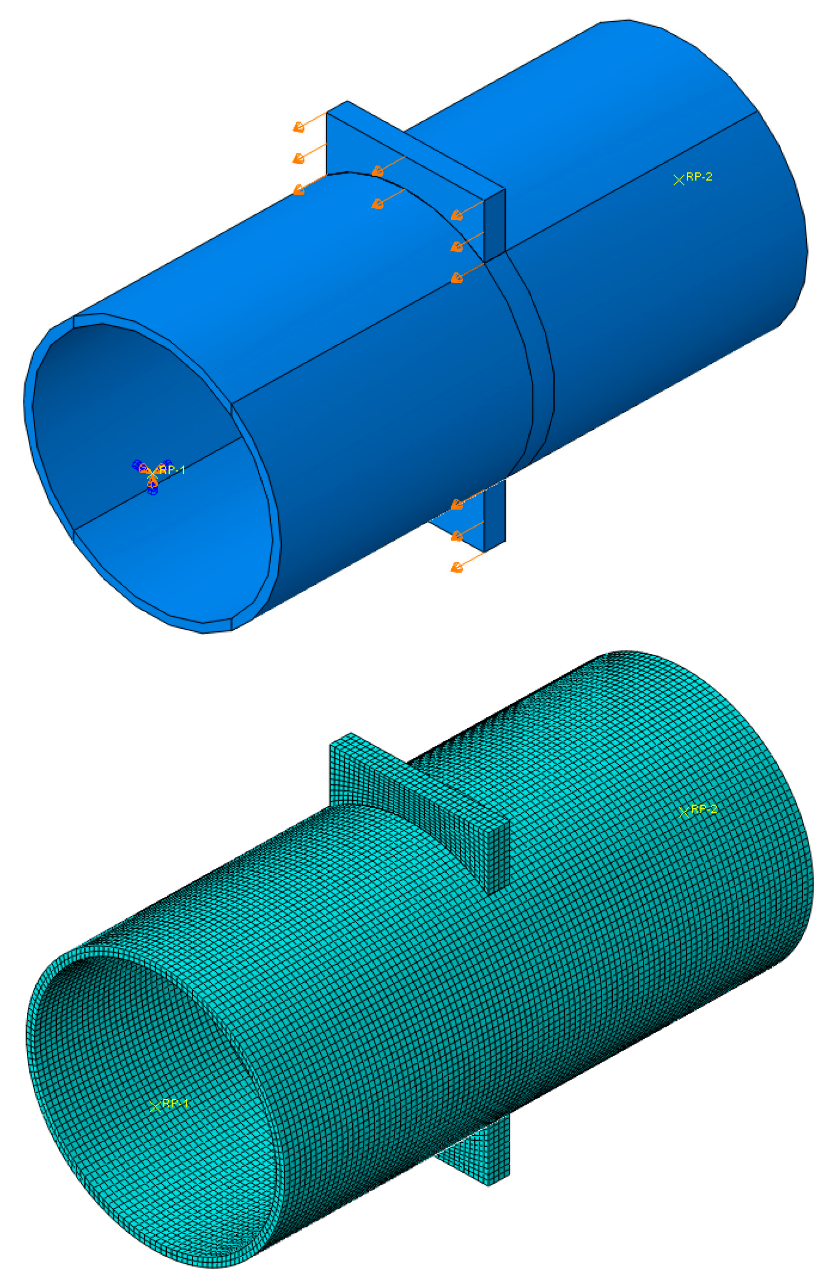
2. Materials and Methods
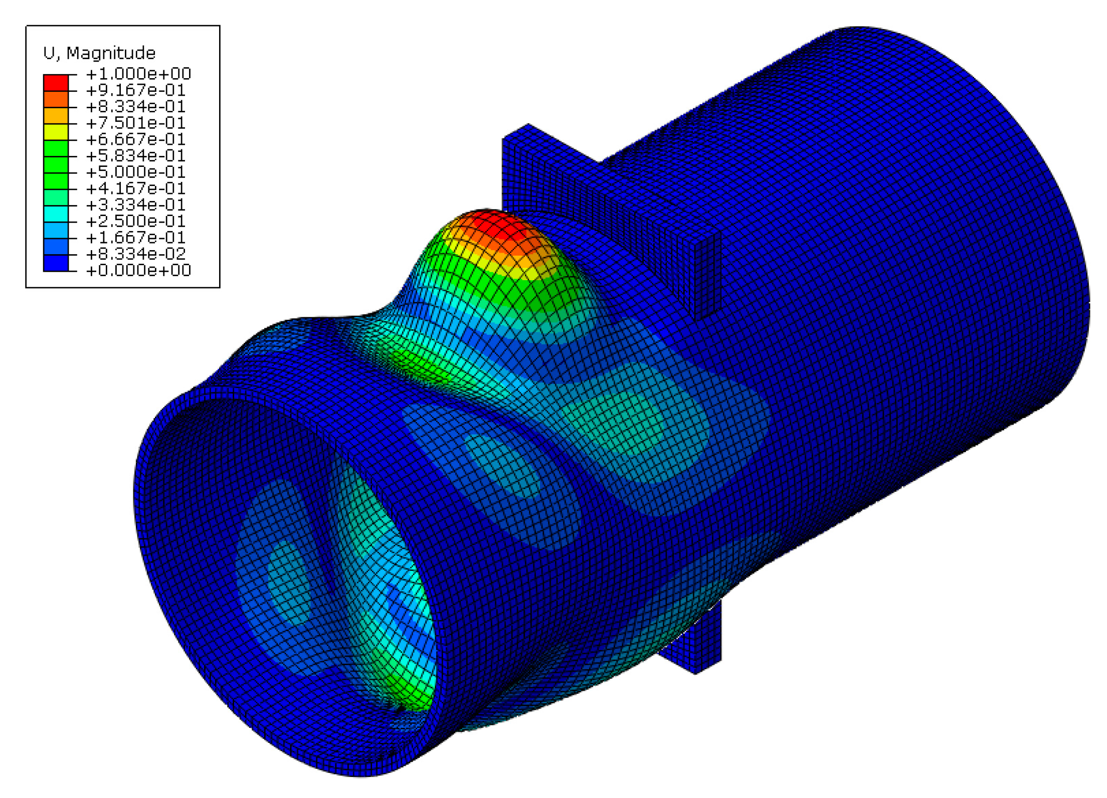
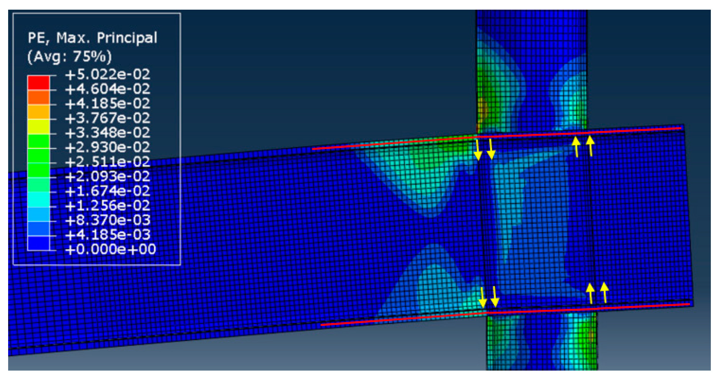
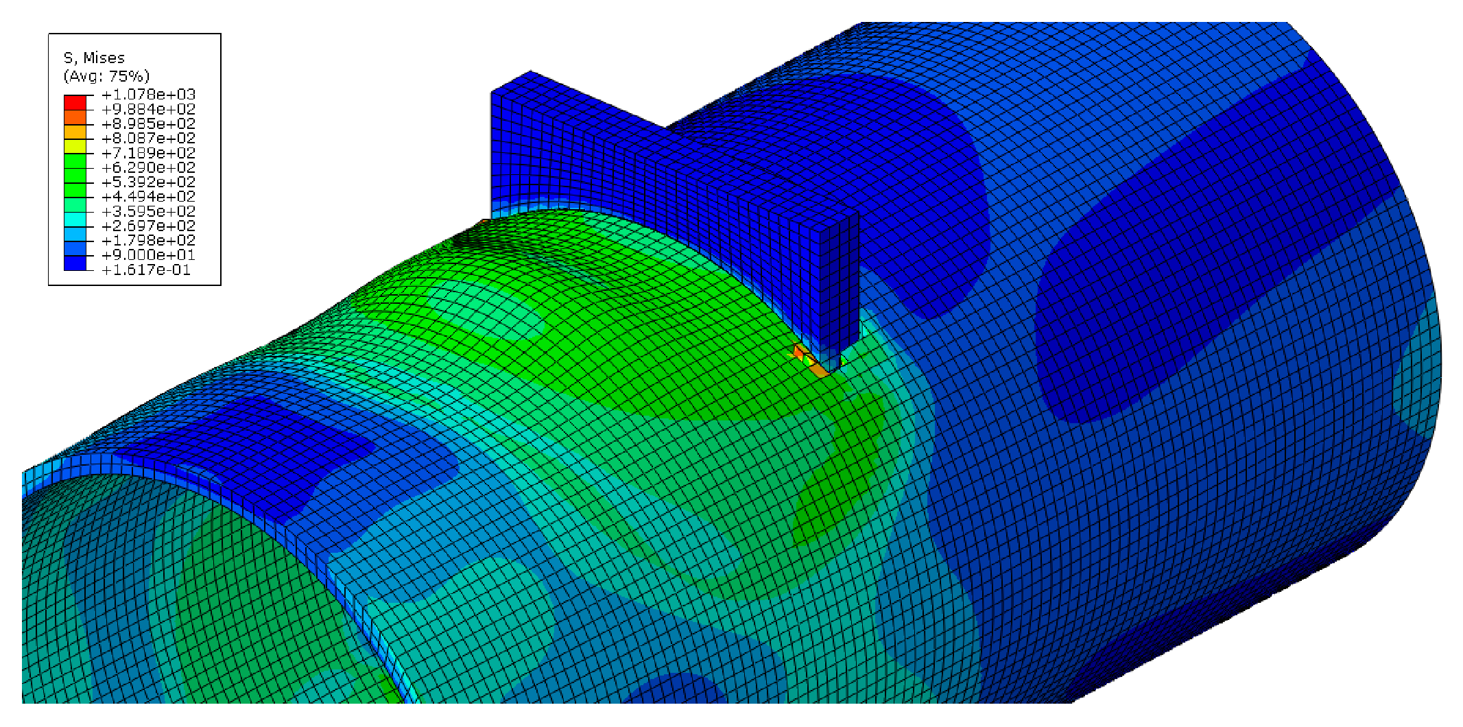
3. Results and Discussion
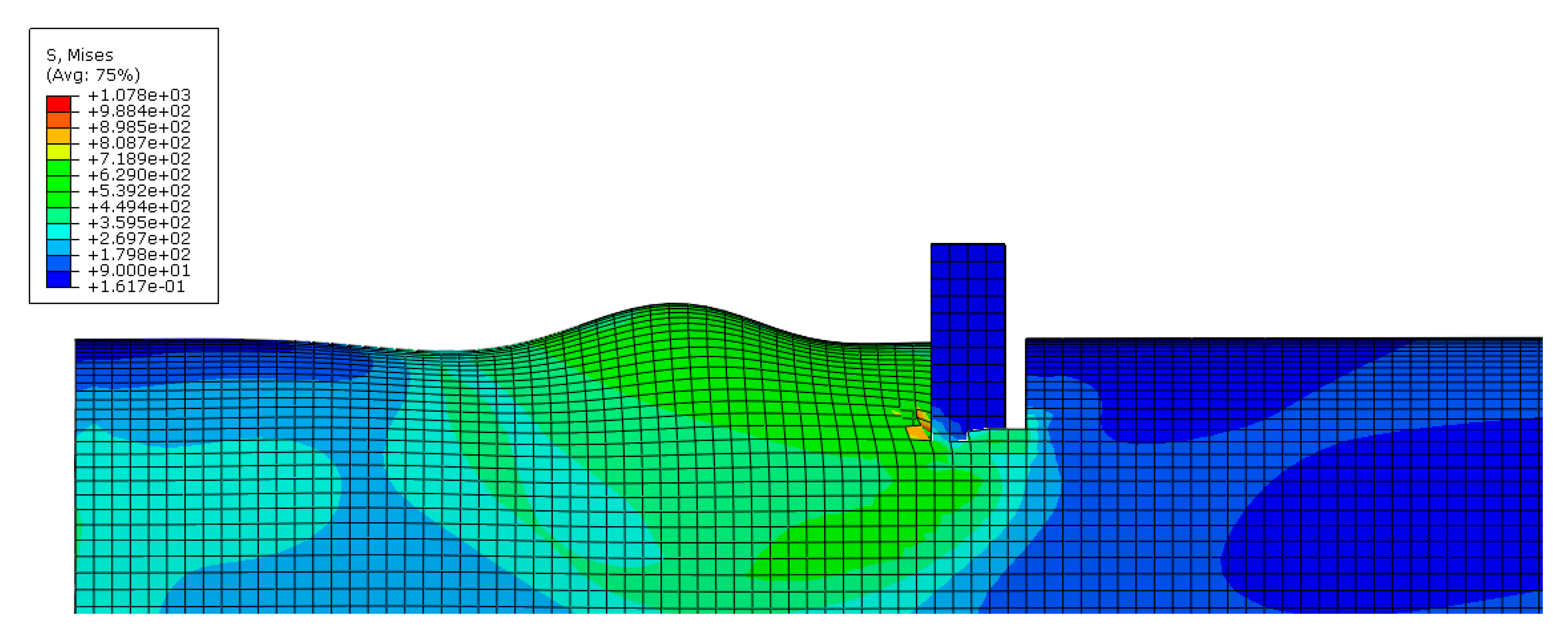
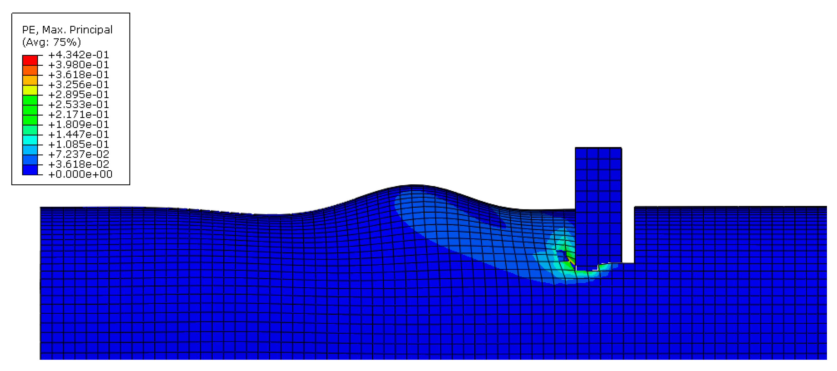
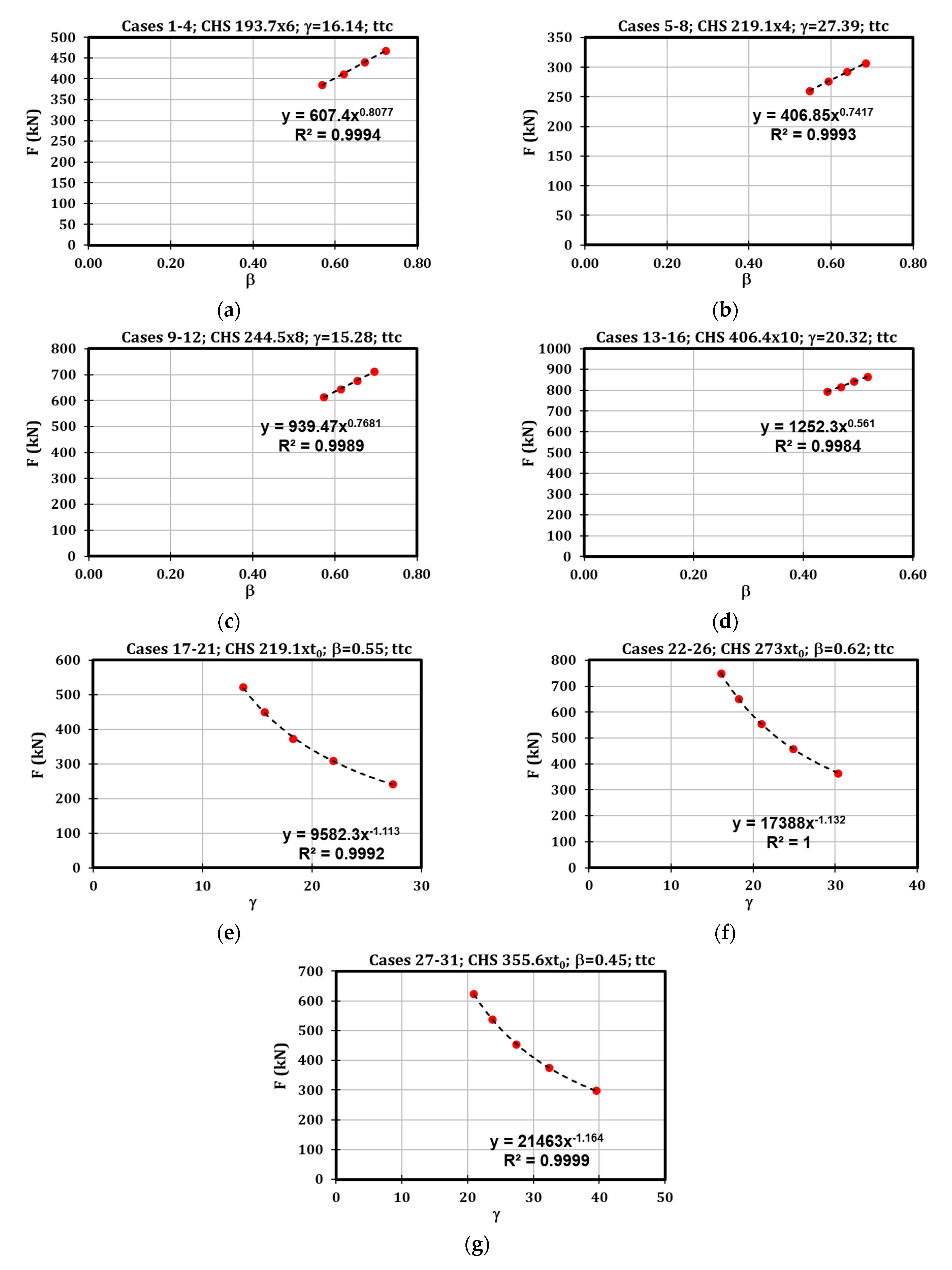
3.1. CHS Tube under Localised Transverse Compression (ttc)
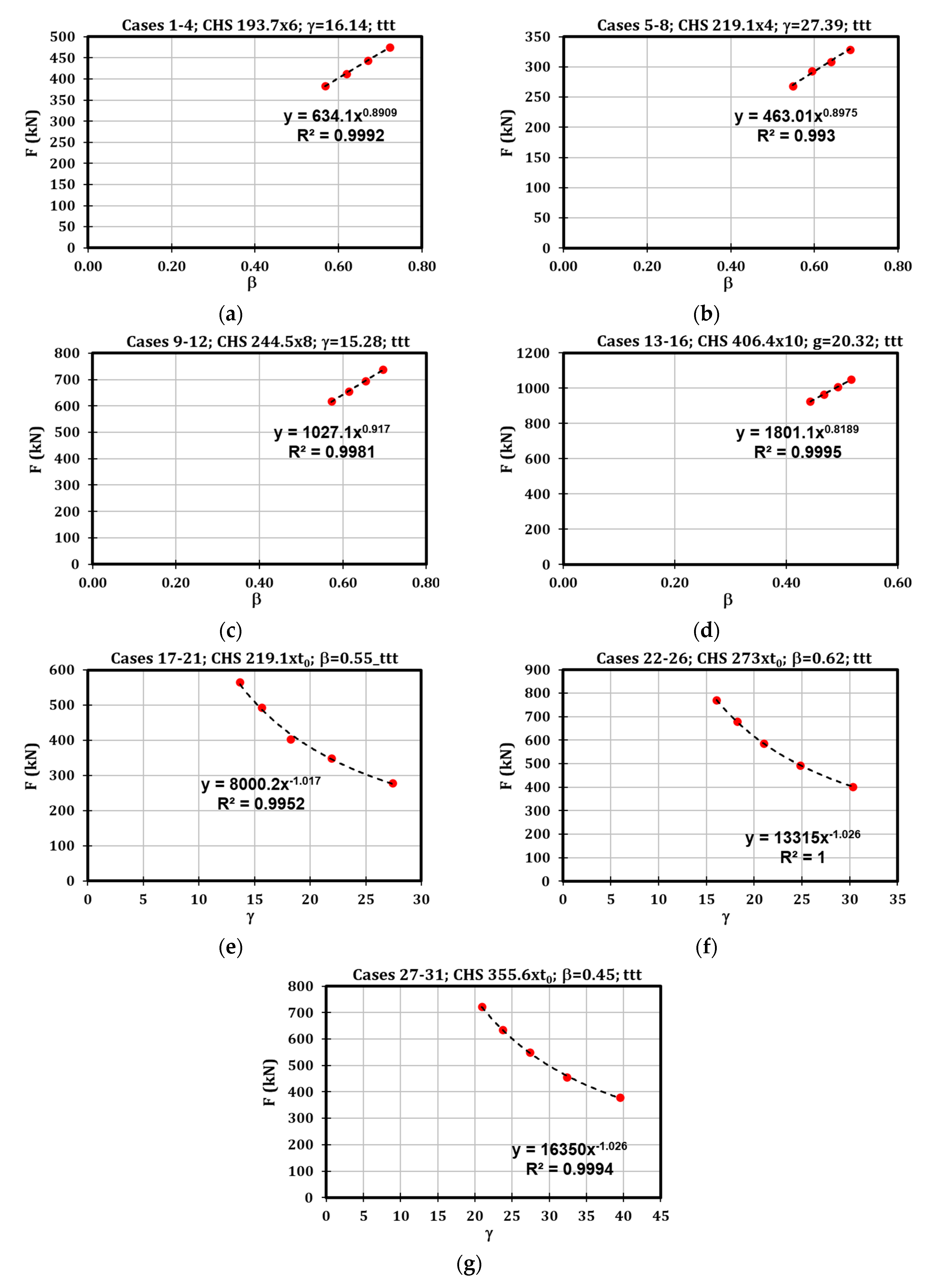
3.2. CHS Tube under Localised Transverse Tension (ttt)
3.3. Stiffness Formulation
4. Conclusions
Author Contributions
Funding
Institutional Review Board Statement
Informed Consent Statement
Data Availability Statement
Conflicts of Interest
References
- Astaneh, A. Seismic Design of Bolted Steel Moment-Resisting Frames; Structural Steel Educational Council: Moraga, CA, USA, 1995. [Google Scholar]
- Makino, Y.; Kurobane, Y.; Paul, J.C.; Orita, Y.; Hiraishi, K. Ultimate capacity of gusset plate-to-tube joints under axial and in plane bending loads. In Proceedings of the 4th International Symposium on Tubular Structures, Delft, The Netherlands, 26–28 June 1991; pp. 424–434. [Google Scholar]
- Makino, Y.; Kurobane, Y.; Ochi, K.; Vegte, G.; Wilmshurst, S.R. Database of Test and Numerical Analysis Results for Unstiffened Tubular Joints; Kumamoto University: Kumamoto, Japan, 1996. [Google Scholar]
- de Winkel, G.D. The Static Strength of I-beam to Circular Hollow Section. Ph.D. Thesis, Delft University of Technology, Delft, The Netherlands, 1998. [Google Scholar]
- EN 1993-1-8; Eurocode 3: Design of Steel Structures—Part 1–8: Design of Joints. CEN: Brussels, Belgium, 2005.
- AIJ. Recommendations for the Design and Fabrication of Tubular Truss Structures in Steel; Architectural Institute of Japan: Tokyo, Japan, 2002. [Google Scholar]
- Sawada, Y.; Idogaki, S.; Sekita, K. Static and Fatigue Tests on T-Joints Stiffened by an Internal Ring. In Proceedings of the Offshore Technology Conference, Houston, TX, USA, 2 May 1979. [Google Scholar]
- Khador, M.; Chan, T.-M. Cyclic behaviour of external diaphragm joint to CHS column with built-in replaceable links. Steel Constr. 2016, 9, 331–338. [Google Scholar] [CrossRef]
- Li, L.; Wang, W.; Chen, Y.; Lu, Y. Experimental investigation of beam-to-tubular column moment connections under column removal scenario. J. Constr. Steel Res. 2013, 88, 244–255. [Google Scholar] [CrossRef]
- Wang, W.; Chen, Y.; Li, W.; Leon, R.T. Bidirectional seismic performance of steel beam to circular tubular column connections with outer diaphragm. Earthq. Eng. Struct. Dyn. 2010, 40, 1063–1081. [Google Scholar] [CrossRef]
- Di Benedetto, S.; Latour, M.; Rizzano, G. Chord failure resistance of 3D cut welded connections with CHS columns and through I-BEAMS. Thin-Walled Struct. 2020, 154, 106821. [Google Scholar] [CrossRef]
- Di Benedetto, S.; Latour, M.; Rizzano, G. Assessment of the stiffness of 3D cut welded connections with CHS columns and through I-BEAMS. Structures 2020, 27, 247–258. [Google Scholar] [CrossRef]
- Voth, A. Branch Plate-to-Circular Hollow Structural Section Connections. Ph.D. Thesis, University of Toronto, Toronto, ON, Canada, 2010. [Google Scholar]
- Kanyilmaz, A.; Castiglioni, C.A.; Brambilla, G.; Gjoka, K.; Galazzi, A.; Raso, S.; Valli, A.; Brugnolli, M.; Hojda, R. Experimental assessment of tolerances for the fabrication of laser-cut steel joints. Ce/Pap. 2017, 1, 776–785. [Google Scholar] [CrossRef]
- Kanyilmaz, A. The problematic nature of steel hollow section joint fabrication, and a remedy using laser cutting technology: A review of research, applications, opportunities. Eng. Struct. 2019, 183, 1027–1048. [Google Scholar] [CrossRef]
- Das, R.; Castiglioni, C.A.; Couchaux, M.; Hoffmeister, B.; Degee, H. Design and analysis of laser-cut based moment resisting passing-through I-beam-to-CHS column joints. J. Constr. Steel Res. 2020, 169, 106015. [Google Scholar] [CrossRef]
- Couchaux, M.; Vyhlas, V.; Kanyilmaz, A.; Hjiaj, M. Passing-through I-beam-to-CHS column joints made by laser cutting technology: Experimental tests and design model. J. Constr. Steel Res. 2021, 176, 106298. [Google Scholar] [CrossRef]
- Steenhuis, M.; Jaspart, J.P.; Gomes, F.; Leino, T. Application of the component method to steel joints. In Proceedings of the Control of the Semi-Rigid Behaviour of Civil Engineering Structural Connections Conference, Liège, Belgium, 17–19 September 1998. [Google Scholar]
- Tschemmernegg, F.; Rubin, A.; Pavlov, A. Application of the component method to composite joints. In Proceeding of the Control of the Semi-Rigid Behaviour of Civil Engineering Structural Connections Conference, Liège, Belgium, 17–19 September 1998. [Google Scholar]
- Wald, F.; Gresnigt, A.M.; Weynand, K.; Jaspart, J.P. Application of the component method to column bases. In Proceeding of the Control of the Semi-Rigid Behaviour of Civil Engineering Structural Connections Conference, Liège, Belgium, 17–19 September 1998. [Google Scholar]
- da Silva, L.S.; Santiago, A.; Vila Real, P. Application of the Component Method to Steel Joints under Fire Loading. In The Paramount Role of Joints into the Reliable Response of Structures: From the Classic Pinned and Rigid Joints to the Notion of Semi-Rigidity; Springer: Berlin/Heidelberg, Germany, 2000. [Google Scholar] [CrossRef]
- Latour, M.; Di Benedetto, S.; Saldutti, A.; Rizzano, G.; Kanyilmaz, A.; Castiglioni, C.A. Component modelling of 3D laser cut joints with CHS columns and through-all members. Thin-Walled Struct. 2023, 182 (Pt A), 110238. [Google Scholar] [CrossRef]
- Abaqus Inc. Analysis User’s Manual Version 6.17; Abaqus Inc.: Palo Alto, CA, USA, 2017. [Google Scholar]
- Faella, C.; Piluso, V.; Rizzano, G. Structural Steel Semirigid Connections; CRC Press: Boca Raton, FL, USA, 2000. [Google Scholar]
- Faralli, A.C. Large Deformation of T-Stub Connection in Bolted Steel Joints. Ph.D. Thesis, University College of London, London, UK, 2019. [Google Scholar]
- Pavlovic, M.; Markovic, Z.; Veljkovic, M.; Budevac, D. Bolted shear connectors vs. headed studs behaviour in push-out tests. J. Constr. Steel Res. 2013, 88, 134–149. [Google Scholar] [CrossRef]
- EN 1993-1-5; Eurocode 3: Design of Steel Structures—Part 1–5: Piling. European Committee for Standardization (CEN): Brussels, Belgium, 2006.
- EN 10034; Structural Steel I and H Sections—Tolerances on Shape and Dimensions. European Committee for Standardization (CEN): Brussels, Belgium, 1995.


| Case | Column Diameter d0 (mm) | Column Thickness t0 (mm) | Plate Width b1 (mm) | β | γ |
|---|---|---|---|---|---|
| 1 | 193.7 | 6 | 110 | 0.57 | 16.14 |
| 2 | 193.7 | 6 | 120 | 0.62 | 16.14 |
| 3 | 193.7 | 6 | 130 | 0.67 | 16.14 |
| 4 | 193.7 | 6 | 140 | 0.72 | 16.14 |
| 5 | 219.1 | 4 | 120 | 0.55 | 27.39 |
| 6 | 219.1 | 4 | 130 | 0.59 | 27.39 |
| 7 | 219.1 | 4 | 140 | 0.64 | 27.39 |
| 8 | 219.1 | 4 | 150 | 0.68 | 27.39 |
| 9 | 244.5 | 8 | 140 | 0.57 | 15.28 |
| 10 | 244.5 | 8 | 150 | 0.61 | 15.28 |
| 11 | 244.5 | 8 | 160 | 0.65 | 15.28 |
| 12 | 244.5 | 8 | 170 | 0.70 | 15.28 |
| 13 | 406.4 | 10 | 180 | 0.44 | 20.32 |
| 14 | 406.4 | 10 | 190 | 0.47 | 20.32 |
| 15 | 406.4 | 10 | 200 | 0.49 | 20.32 |
| 16 | 406.4 | 10 | 210 | 0.52 | 20.32 |
| 17 | 219.1 | 4 | 120 | 0.55 | 27.39 |
| 18 | 219.1 | 5 | 120 | 0.55 | 21.91 |
| 19 | 219.1 | 6 | 120 | 0.55 | 18.26 |
| 20 | 219.1 | 7 | 120 | 0.55 | 15.65 |
| 21 | 219.1 | 8 | 120 | 0.55 | 13.69 |
| 22 | 273 | 4.5 | 170 | 0.62 | 30.33 |
| 23 | 273 | 5.5 | 170 | 0.62 | 24.82 |
| 24 | 273 | 6.5 | 170 | 0.62 | 21.00 |
| 25 | 273 | 7.5 | 170 | 0.62 | 18.20 |
| 26 | 273 | 8.5 | 170 | 0.62 | 16.06 |
| 27 | 355.6 | 4.5 | 160 | 0.45 | 39.51 |
| 28 | 355.6 | 5.5 | 160 | 0.45 | 32.33 |
| 29 | 355.6 | 6.5 | 160 | 0.45 | 27.35 |
| 30 | 355.6 | 7.5 | 160 | 0.45 | 23.71 |
| 31 | 355.6 | 8.5 | 160 | 0.45 | 20.92 |
| Case | d0 (mm) | t0 (mm) | b1 (mm) | β | γ | Fttc (kN) | Fttt (kN) | kttt/ttc (N/mm) |
|---|---|---|---|---|---|---|---|---|
| 1 | 193.7 | 6 | 110 | 0.57 | 16.14 | 385 | 384 | 2,669,973 |
| 2 | 193.7 | 6 | 120 | 0.62 | 16.14 | 411 | 412 | 2,836,234 |
| 3 | 193.7 | 6 | 130 | 0.67 | 16.14 | 440 | 444 | 3,040,961 |
| 4 | 193.7 | 6 | 140 | 0.72 | 16.14 | 468 | 476 | 3,278,204 |
| 5 | 219.1 | 4 | 120 | 0.55 | 27.39 | 260 | 268 | 1,521,235 |
| 6 | 219.1 | 4 | 130 | 0.59 | 27.39 | 276 | 293 | 1,609,283 |
| 7 | 219.1 | 4 | 140 | 0.64 | 27.39 | 293 | 309 | 1,703,291 |
| 8 | 219.1 | 4 | 150 | 0.68 | 27.39 | 307 | 329 | 1,769,345 |
| 9 | 244.5 | 8 | 140 | 0.57 | 15.28 | 613 | 618 | 3,383,171 |
| 10 | 244.5 | 8 | 150 | 0.61 | 15.28 | 645 | 654 | 3,560,892 |
| 11 | 244.5 | 8 | 160 | 0.65 | 15.28 | 677 | 694 | 3,757,766 |
| 12 | 244.5 | 8 | 170 | 0.70 | 15.28 | 712 | 738 | 4,015,597 |
| 13 | 406.4 | 10 | 180 | 0.44 | 20.32 | 793 | 926 | 2,909,890 |
| 14 | 406.4 | 10 | 190 | 0.47 | 20.32 | 816 | 965 | 2,931,171 |
| 15 | 406.4 | 10 | 200 | 0.49 | 20.32 | 843 | 1008 | 2,944,675 |
| 16 | 406.4 | 10 | 210 | 0.52 | 20.32 | 864 | 1049 | 2,907,151 |
| 17 | 219.1 | 4 | 120 | 0.55 | 27.39 | 242 | 279 | 2,192,166 |
| 18 | 219.1 | 5 | 120 | 0.55 | 21.91 | 309 | 349 | 1,872,032 |
| 19 | 219.1 | 6 | 120 | 0.55 | 18.26 | 373 | 404 | 2,168,739 |
| 20 | 219.1 | 7 | 120 | 0.55 | 15.65 | 451 | 493 | 2,859,602 |
| 21 | 219.1 | 8 | 120 | 0.55 | 13.69 | 523 | 565 | 3,371,274 |
| 22 | 273 | 4.5 | 170 | 0.62 | 30.33 | 365 | 403 | 1,617,685 |
| 23 | 273 | 5.5 | 170 | 0.62 | 24.82 | 458 | 493 | 2,076,532 |
| 24 | 273 | 6.5 | 170 | 0.62 | 21.00 | 554 | 587 | 2,568,008 |
| 25 | 273 | 7.5 | 170 | 0.62 | 18.20 | 651 | 679 | 3,070,647 |
| 26 | 273 | 8.5 | 170 | 0.62 | 16.06 | 750 | 772 | 3,588,121 |
| 27 | 355.6 | 4.5 | 160 | 0.45 | 39.51 | 298 | 379 | 1,103,192 |
| 28 | 355.6 | 5.5 | 160 | 0.45 | 32.33 | 375 | 456 | 1,399,880 |
| 29 | 355.6 | 6.5 | 160 | 0.45 | 27.35 | 454 | 550 | 1,736,309 |
| 30 | 355.6 | 7.5 | 160 | 0.45 | 23.71 | 539 | 636 | 2,130,192 |
| 31 | 355.6 | 8.5 | 160 | 0.45 | 20.92 | 625 | 723 | 2,529,651 |
| Test | d0 (mm) | t0 (mm) | b1 (mm) | β | γ | Fttc, FEM (kN) | Fttc, proposal (kN) | Fttc, proposal/Fttc, FEM |
|---|---|---|---|---|---|---|---|---|
| 1 | 193.7 | 6 | 110 | 0.57 | 16.14 | 385 | 312 | 0.81 |
| 2 | 193.7 | 6 | 120 | 0.62 | 16.14 | 411 | 354 | 0.86 |
| 3 | 193.7 | 6 | 130 | 0.67 | 16.14 | 440 | 398 | 0.90 |
| 4 | 193.7 | 6 | 140 | 0.72 | 16.14 | 468 | 444 | 0.95 |
| 5 | 219.1 | 4 | 120 | 0.55 | 27.39 | 260 | 248 | 0.95 |
| 6 | 219.1 | 4 | 130 | 0.59 | 27.39 | 276 | 278 | 1.01 |
| 7 | 219.1 | 4 | 140 | 0.64 | 27.39 | 293 | 310 | 1.06 |
| 8 | 219.1 | 4 | 150 | 0.68 | 27.39 | 307 | 343 | 1.12 |
| 9 | 244.5 | 8 | 140 | 0.57 | 15.28 | 613 | 526 | 0.86 |
| 10 | 244.5 | 8 | 150 | 0.61 | 15.28 | 645 | 582 | 0.90 |
| 11 | 244.5 | 8 | 160 | 0.65 | 15.28 | 677 | 639 | 0.94 |
| 12 | 244.5 | 8 | 170 | 0.70 | 15.28 | 712 | 698 | 0.98 |
| 13 | 406.4 | 10 | 180 | 0.44 | 20.32 | 793 | 795 | 1.00 |
| 14 | 406.4 | 10 | 190 | 0.47 | 20.32 | 816 | 860 | 1.05 |
| 15 | 406.4 | 10 | 200 | 0.49 | 20.32 | 843 | 927 | 1.10 |
| 16 | 406.4 | 10 | 210 | 0.52 | 20.32 | 864 | 995 | 1.15 |
| 17 | 219.1 | 4 | 120 | 0.55 | 27.39 | 242 | 248 | 1.02 |
| 18 | 219.1 | 5 | 120 | 0.55 | 21.91 | 309 | 296 | 0.96 |
| 19 | 219.1 | 6 | 120 | 0.55 | 18.26 | 373 | 343 | 0.92 |
| 20 | 219.1 | 7 | 120 | 0.55 | 15.65 | 451 | 388 | 0.86 |
| 21 | 219.1 | 8 | 120 | 0.55 | 13.69 | 523 | 432 | 0.83 |
| 22 | 273 | 4.5 | 170 | 0.62 | 30.33 | 365 | 427 | 1.17 |
| 23 | 273 | 5.5 | 170 | 0.62 | 24.82 | 458 | 502 | 1.10 |
| 24 | 273 | 6.5 | 170 | 0.62 | 21.00 | 554 | 574 | 1.04 |
| 25 | 273 | 7.5 | 170 | 0.62 | 18.20 | 651 | 644 | 0.99 |
| 26 | 273 | 8.5 | 170 | 0.62 | 16.06 | 750 | 712 | 0.95 |
| 27 | 355.6 | 4.5 | 160 | 0.45 | 39.51 | 298 | 365 | 1.23 |
| 28 | 355.6 | 5.5 | 160 | 0.45 | 32.33 | 375 | 429 | 1.14 |
| 29 | 355.6 | 6.5 | 160 | 0.45 | 27.35 | 454 | 490 | 1.08 |
| 30 | 355.6 | 7.5 | 160 | 0.45 | 23.71 | 539 | 550 | 1.02 |
| 31 | 355.6 | 8.5 | 160 | 0.45 | 20.92 | 625 | 608 | 0.97 |
| Mean | 1.00 | |||||||
| Standard deviation | 0.104 | |||||||
| Coefficient of variation | 0.104 | |||||||
| Test | d0 (mm) | t0 (mm) | b1 (mm) | β | γ | Fttt, FEM (kN) | Fttt, proposal (kN) | Fttt, proposal/Fttt, FEM |
|---|---|---|---|---|---|---|---|---|
| 1 | 193.7 | 6 | 110 | 0.57 | 16.14 | 384 | 344 | 0.90 |
| 2 | 193.7 | 6 | 120 | 0.62 | 16.14 | 412 | 379 | 0.92 |
| 3 | 193.7 | 6 | 130 | 0.67 | 16.14 | 444 | 415 | 0.93 |
| 4 | 193.7 | 6 | 140 | 0.72 | 16.14 | 476 | 451 | 0.95 |
| 5 | 219.1 | 4 | 120 | 0.55 | 27.39 | 268 | 271 | 1.01 |
| 6 | 219.1 | 4 | 130 | 0.59 | 27.39 | 293 | 297 | 1.01 |
| 7 | 219.1 | 4 | 140 | 0.64 | 27.39 | 309 | 323 | 1.04 |
| 8 | 219.1 | 4 | 150 | 0.68 | 27.39 | 329 | 349 | 1.06 |
| 9 | 244.5 | 8 | 140 | 0.57 | 15.28 | 618 | 579 | 0.94 |
| 10 | 244.5 | 8 | 150 | 0.61 | 15.28 | 654 | 626 | 0.96 |
| 11 | 244.5 | 8 | 160 | 0.65 | 15.28 | 694 | 673 | 0.97 |
| 12 | 244.5 | 8 | 170 | 0.70 | 15.28 | 738 | 720 | 0.98 |
| 13 | 406.4 | 10 | 180 | 0.44 | 20.32 | 926 | 945 | 1.02 |
| 14 | 406.4 | 10 | 190 | 0.47 | 20.32 | 965 | 1004 | 1.04 |
| 15 | 406.4 | 10 | 200 | 0.49 | 20.32 | 1008 | 1064 | 1.05 |
| 16 | 406.4 | 10 | 210 | 0.52 | 20.32 | 1049 | 1123 | 1.07 |
| 17 | 219.1 | 4 | 120 | 0.55 | 27.39 | 279 | 271 | 0.97 |
| 18 | 219.1 | 5 | 120 | 0.55 | 21.91 | 349 | 327 | 0.94 |
| 19 | 219.1 | 6 | 120 | 0.55 | 18.26 | 404 | 381 | 0.94 |
| 20 | 219.1 | 7 | 120 | 0.55 | 15.65 | 493 | 434 | 0.88 |
| 21 | 219.1 | 8 | 120 | 0.55 | 13.69 | 565 | 485 | 0.86 |
| 22 | 273 | 4.5 | 170 | 0.62 | 30.33 | 403 | 447 | 1.11 |
| 23 | 273 | 5.5 | 170 | 0.62 | 24.82 | 493 | 528 | 1.07 |
| 24 | 273 | 6.5 | 170 | 0.62 | 21.00 | 587 | 608 | 1.04 |
| 25 | 273 | 7.5 | 170 | 0.62 | 18.20 | 679 | 685 | 1.01 |
| 26 | 273 | 8.5 | 170 | 0.62 | 16.06 | 772 | 761 | 0.99 |
| 27 | 355.6 | 4.5 | 160 | 0.45 | 39.51 | 379 | 422 | 1.11 |
| 28 | 355.6 | 5.5 | 160 | 0.45 | 32.33 | 456 | 499 | 1.09 |
| 29 | 355.6 | 6.5 | 160 | 0.45 | 27.35 | 550 | 574 | 1.04 |
| 30 | 355.6 | 7.5 | 160 | 0.45 | 23.71 | 636 | 647 | 1.02 |
| 31 | 355.6 | 8.5 | 160 | 0.45 | 20.92 | 723 | 719 | 0.99 |
| Mean | 1.00 | |||||||
| Standard deviation | 0.066 | |||||||
| Coefficient of variation | 0.066 | |||||||
| Test | d0 (mm) | t0 (mm) | b1 (mm) | β | γ | kFEM (N/mm) | kproposal (N/mm) | kproposal/kFEM |
|---|---|---|---|---|---|---|---|---|
| 1 | 193.7 | 6 | 110 | 0.57 | 16.14 | 2,669,973 | 2,176,253 | 0.82 |
| 2 | 193.7 | 6 | 120 | 0.62 | 16.14 | 2,836,234 | 2,420,718 | 0.85 |
| 3 | 193.7 | 6 | 130 | 0.67 | 16.14 | 3,040,961 | 2,669,784 | 0.88 |
| 4 | 193.7 | 6 | 140 | 0.72 | 16.14 | 3,278,204 | 2,923,173 | 0.89 |
| 5 | 219.1 | 4 | 120 | 0.55 | 27.39 | 1,521,235 | 1,539,651 | 1.01 |
| 6 | 219.1 | 4 | 130 | 0.59 | 27.39 | 1,609,283 | 1,698,065 | 1.06 |
| 7 | 219.1 | 4 | 140 | 0.64 | 27.39 | 1,703,291 | 1,859,228 | 1.09 |
| 8 | 219.1 | 4 | 150 | 0.68 | 27.39 | 1,769,345 | 2,022,986 | 1.14 |
| 9 | 244.5 | 8 | 140 | 0.57 | 15.28 | 3,383,171 | 2,899,806 | 0.86 |
| 10 | 244.5 | 8 | 150 | 0.61 | 15.28 | 3,560,892 | 3,155,217 | 0.89 |
| 11 | 244.5 | 8 | 160 | 0.65 | 15.28 | 3,757,766 | 3,414,466 | 0.91 |
| 12 | 244.5 | 8 | 170 | 0.70 | 15.28 | 4,015,597 | 3,677,363 | 0.92 |
| 13 | 406.4 | 10 | 180 | 0.44 | 20.32 | 2,909,890 | 2,799,625 | 0.96 |
| 14 | 406.4 | 10 | 190 | 0.47 | 20.32 | 2,931,171 | 2,991,089 | 1.02 |
| 15 | 406.4 | 10 | 200 | 0.49 | 20.32 | 2,944,675 | 3,184,819 | 1.08 |
| 16 | 406.4 | 10 | 210 | 0.52 | 20.32 | 2,907,151 | 3,380,727 | 1.16 |
| 17 | 219.1 | 4 | 120 | 0.55 | 27.39 | 2,192,166 | 1,539,651 | 0.70 |
| 18 | 219.1 | 5 | 120 | 0.55 | 21.91 | 1,872,032 | 1,842,133 | 0.98 |
| 19 | 219.1 | 6 | 120 | 0.55 | 18.26 | 2,168,739 | 2,132,891 | 0.98 |
| 20 | 219.1 | 7 | 120 | 0.55 | 15.65 | 2,859,602 | 2,414,249 | 0.84 |
| 21 | 219.1 | 8 | 120 | 0.55 | 13.69 | 3,371,274 | 2,687,802 | 0.80 |
| 22 | 273 | 4.5 | 170 | 0.62 | 30.33 | 1,617,685 | 2,067,695 | 1.28 |
| 23 | 273 | 5.5 | 170 | 0.62 | 24.82 | 2,076,532 | 2,429,628 | 1.17 |
| 24 | 273 | 6.5 | 170 | 0.62 | 21.00 | 2,568,008 | 2,778,803 | 1.08 |
| 25 | 273 | 7.5 | 170 | 0.62 | 18.20 | 3,070,647 | 3,117,552 | 1.02 |
| 26 | 273 | 8.5 | 170 | 0.62 | 16.06 | 3,588,121 | 3,447,527 | 0.96 |
| 27 | 355.6 | 4.5 | 160 | 0.45 | 39.51 | 1,103,192 | 1,463,307 | 1.33 |
| 28 | 355.6 | 5.5 | 160 | 0.45 | 32.33 | 1,399,880 | 1,719,447 | 1.23 |
| 29 | 355.6 | 6.5 | 160 | 0.45 | 27.35 | 1,736,309 | 1,966,558 | 1.13 |
| 30 | 355.6 | 7.5 | 160 | 0.45 | 23.71 | 2,130,192 | 2,206,290 | 1.04 |
| 31 | 355.6 | 8.5 | 160 | 0.45 | 20.92 | 2,529,651 | 2,439,813 | 0.96 |
| Mean | 1.00 | |||||||
| Standard deviation | 0.144 | |||||||
| Coefficient of variation | 0.144 | |||||||
Disclaimer/Publisher’s Note: The statements, opinions and data contained in all publications are solely those of the individual author(s) and contributor(s) and not of MDPI and/or the editor(s). MDPI and/or the editor(s) disclaim responsibility for any injury to people or property resulting from any ideas, methods, instructions or products referred to in the content. |
© 2023 by the authors. Licensee MDPI, Basel, Switzerland. This article is an open access article distributed under the terms and conditions of the Creative Commons Attribution (CC BY) license (https://creativecommons.org/licenses/by/4.0/).
Share and Cite
Latour, M.; Di Benedetto, S.; Francavilla, A.B.; Saldutti, A.; Rizzano, G. Mechanical Modelling of the Strength and Stiffness of Circular Hollow Section Tube under Localised Transverse Compression and Tension. Materials 2023, 16, 2641. https://doi.org/10.3390/ma16072641
Latour M, Di Benedetto S, Francavilla AB, Saldutti A, Rizzano G. Mechanical Modelling of the Strength and Stiffness of Circular Hollow Section Tube under Localised Transverse Compression and Tension. Materials. 2023; 16(7):2641. https://doi.org/10.3390/ma16072641
Chicago/Turabian StyleLatour, Massimo, Sabatino Di Benedetto, Antonella Bianca Francavilla, Alberico Saldutti, and Gianvittorio Rizzano. 2023. "Mechanical Modelling of the Strength and Stiffness of Circular Hollow Section Tube under Localised Transverse Compression and Tension" Materials 16, no. 7: 2641. https://doi.org/10.3390/ma16072641