
Hybrid Fluoro-Based Polymers/Graphite Foil for H2/Natural Gas Separation
 , ,
, ,  ,
,
Abstract
:1. Introduction
2. Materials and Methods
3. Results and Discussion
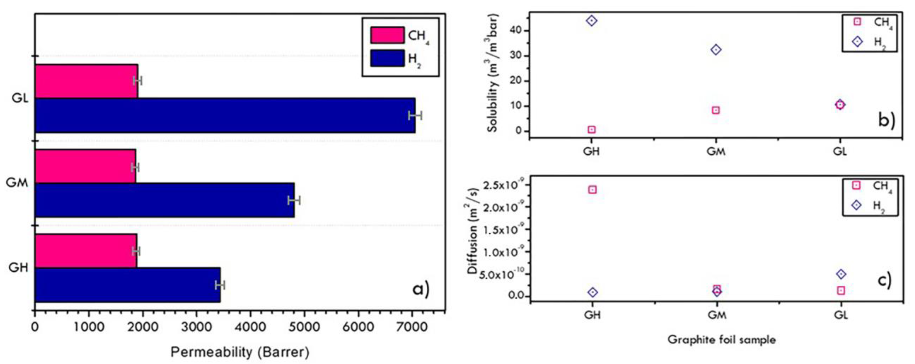
3.1. Graphite Substrate Characterization
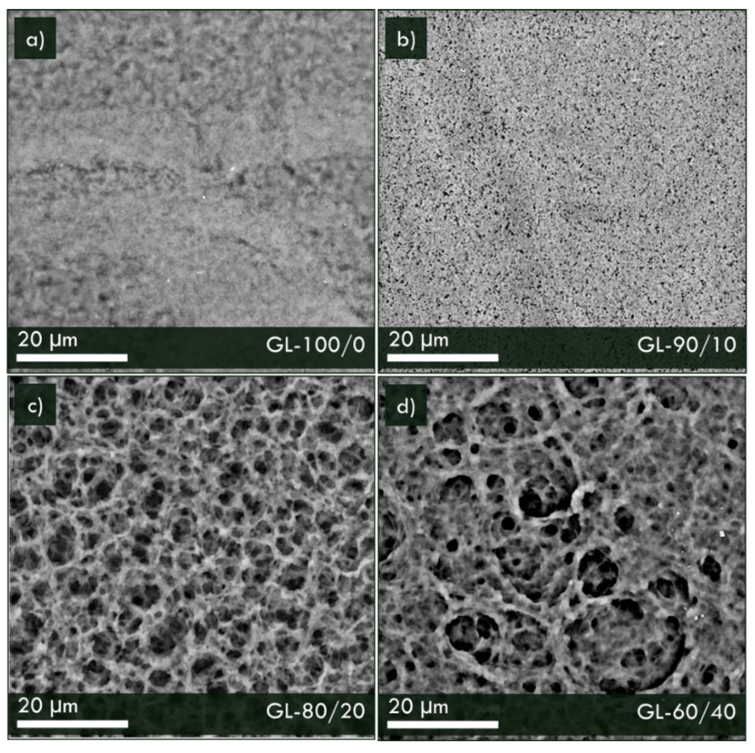
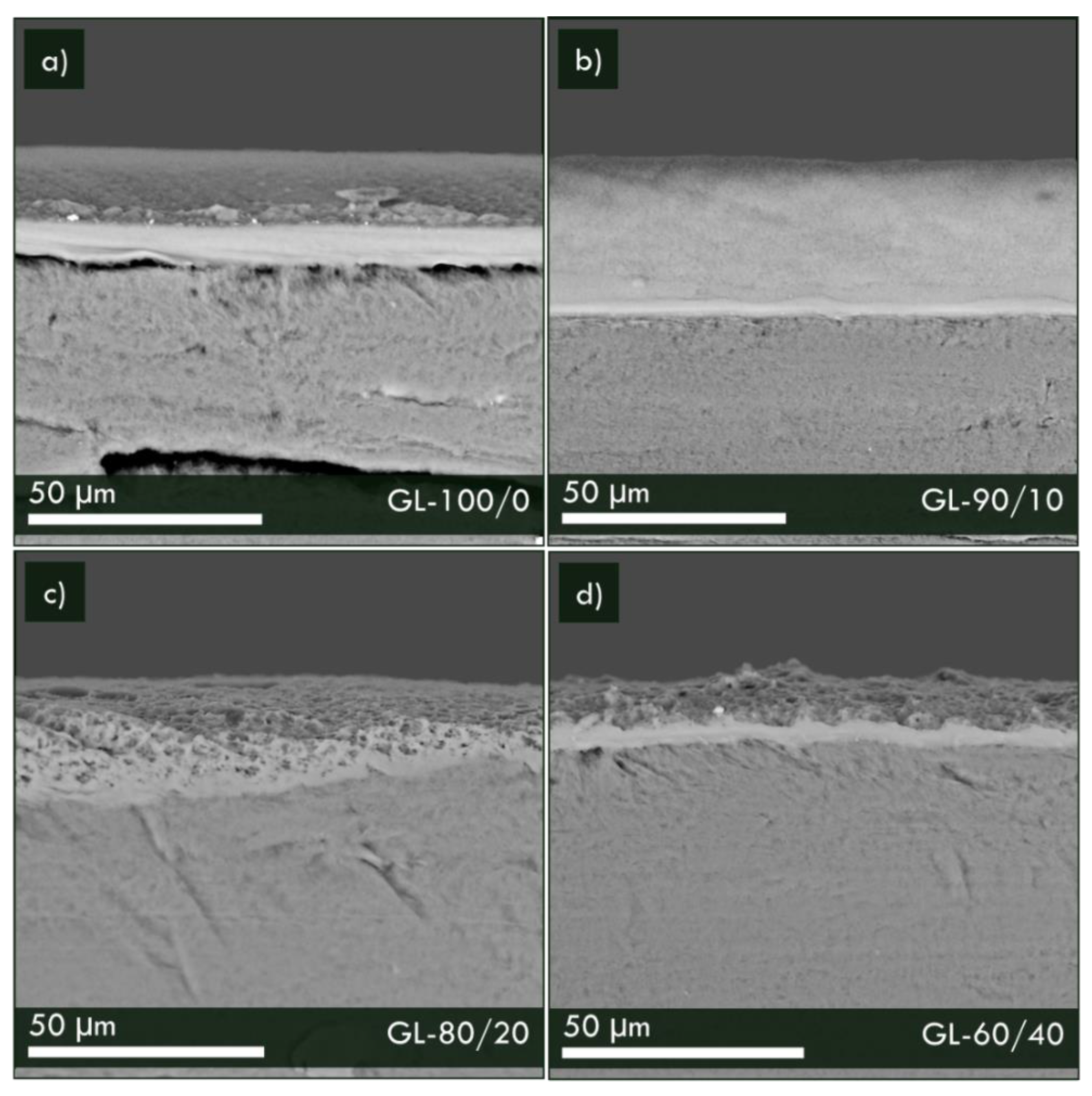
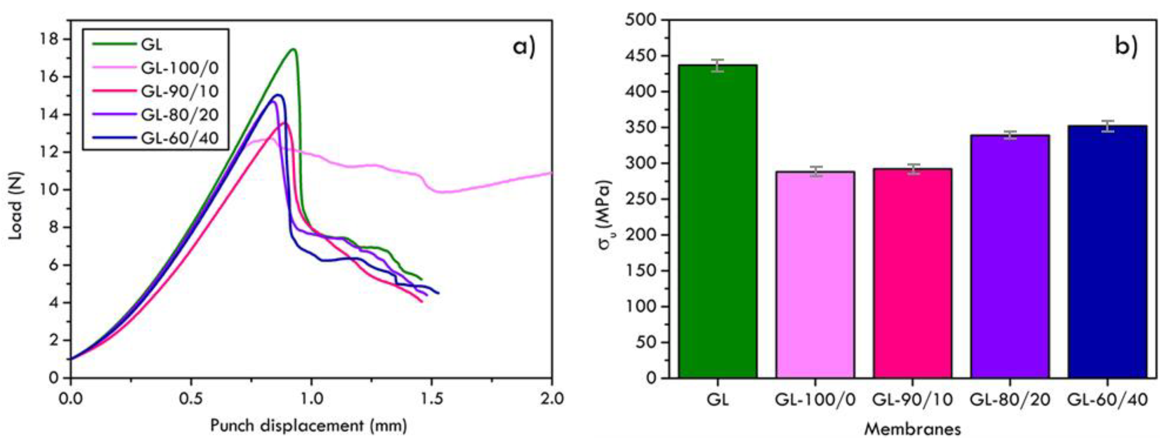
3.2. Polymers/Graphite Membranes
4. Conclusions
Author Contributions
Funding
Conflicts of Interest
References
- Razi, F.; Dincer, I. Challenges, opportunities and future directions in hydrogen sector development in Canada. Int. J. Hydrogen Energy 2022, 47, 9083–9102. [Google Scholar] [CrossRef]
- Hu, G.; Chen, C.; Lu, H.T.; Wu, Y.; Liu, C.; Tao, L.; Men, Y.; He, G.; Li, K.G. A Review of Technical Advances, Barriers, and Solutions in the Power to Hydrogen (P2H) Roadmap. Engineering 2020, 6, 1364–1380. [Google Scholar] [CrossRef]
- Wulf, C.; Kaltschmitt, M. Hydrogen supply chains for mobility-Environmental and economic assessment. Sustainability 2018, 10, 1699. [Google Scholar] [CrossRef] [Green Version]
- Lu, L.; Sun, H.; Peng, F.; Jiang, Z. Novel graphite-filled PVA/CS hybrid membrane for pervaporation of benzene/cyclohexane mixtures. J. Memb. Sci. 2006, 281, 245–252. [Google Scholar] [CrossRef]
- Wolf, A.; Zander, N. Green hydrogen in Europe: Do strategies meet expectations? Intereconomics 2021, 56, 316–323. [Google Scholar] [CrossRef]
- Okunlola, A.; Giwa, T.; Di Lullo, G.; Davis, M.; Gemechu, E.; Kumar, A. Techno-economic assessment of low-carbon hydrogen export from Western Canada to Eastern Canada, the USA, the Asia-Pacific, and Europe. Int. J. Hydrogen Energy 2022, 47, 6453–6477. [Google Scholar] [CrossRef]
- Mahajan, D.; Tan, K.; Venkatesh, T.; Kileti, P.; Clayton, C.R. Hydrogen Blending in Gas Pipeline Networks—A Review. Energies 2022, 15, 3582. [Google Scholar] [CrossRef]
- Chae, M.J.; Kim, J.H.; Moon, B.; Park, S.; Lee, Y.S. The present condition and outlook for hydrogen-natural gas blending technology. Korean J. Chem. Eng. 2022, 39, 251–262. [Google Scholar] [CrossRef]
- Witkowski, A.; Rusin, A.; Majkut, M.; Stolecka, K. Analysis of compression and transport of the methane/hydrogen mixture in existing natural gas pipelines. Int. J. Press. Vessel. Pip. 2018, 166, 24–34. [Google Scholar] [CrossRef]
- Pellegrini, M.; Guzzini, A.; Saccani, C. A preliminary assessment of the potential of low percentage green hydrogen blending in the Italian Natural Gas Network. Energies 2020, 13, 5570. [Google Scholar] [CrossRef]
- Melaina, M.W.; Antonia, O.; Penev, M. Blending Hydrogen into Natural Gas Pipeline Networks: A Review of Key Issues. Technical Report NREL/TP-5600-51995, National Renewabler Energy Laboratory. Contract 2013, 303, 275–3000. [Google Scholar]
- Ekhtiari, A.; Flynn, D.; Syron, E. Investigation of the multi-point injection of green hydrogen from curtailed renewable power into a gas network. Energies 2020, 13, 6047. [Google Scholar] [CrossRef]
- Eames, I.; Austin, M.; Wojcik, A. Injection of gaseous hydrogen into a natural gas pipeline. Int. J. Hydrogen Energy 2022, 47, 25745–25754. [Google Scholar] [CrossRef]
- Atkinson, S. Separation technology enables hydrogen to be extracted from natural gas pipeline networks. Membr. Technol. 2021, 2021, 6. [Google Scholar] [CrossRef]
- Vermaak, L.; Neomagus, H.W.J.P.; Bessarabov, D.G. Hydrogen separation and purification from various gas mixtures by means of electrochemical membrane technology in the temperature range 100–160 °C. Membranes. 2021, 11, 282. [Google Scholar] [CrossRef] [PubMed]
- Wang, Z.; Zhu, L.; Sun, S.; Wang, J.; Yan, W. One-Dimensional Nanomaterials in Resistive Gas Sensor: From Material Design to Application. Chemosens 2021, 9, 198. [Google Scholar] [CrossRef]
- Grainger, D. Development of Carbon Membranes for Hydrogen Recovery; NTNU: Trondheim, Norway, 2007; ISBN 9788247142974. Available online: https://ntnuopen.ntnu.no/ntnu-xmlui/handle/11250/248707 (accessed on 9 January 2023).
- Al-Mufachi, N.A.; Rees, N.V.; Steinberger-Wilkens, R. Hydrogen selective membranes: A review of palladium-based dense metal membranes. Renew. Sustain. Energy Rev. 2015, 47, 540–551. [Google Scholar] [CrossRef]
- Kluiters, S.C.A. Status Review on MEMBRANE systems for Hydrogen Separation; Energy Cent. Netherlands: Petten, The Netherlands, 2004. [Google Scholar]
- Satilmis, B.; Uyar, T. Development of superhydrophobic electrospun fibrous membrane of polymers of intrinsic microporosity (PIM-2). Eur. Polym. J. 2019, 112, 87–94. [Google Scholar] [CrossRef]
- Genduso, G.; Ghanem, B.S.; Wang, Y.; Pinnau, I. Synthesis and gas-permeation characterization of a novel high-surface area polyamide derived from 1,3,6,8-tetramethyl-2,7-diaminotriptycene: Towards polyamides of intrinsic microporosity (PIM-PAs). Polymers 2019, 11, 361. [Google Scholar] [CrossRef] [PubMed] [Green Version]
- Fernández-Castro, P.; Ortiz, A.; Gorri, D. Exploring the potential application of matrimid® and ZIFs-based membranes for hydrogen recovery: A review. Polymers 2021, 13, 1292. [Google Scholar] [CrossRef] [PubMed]
- Longo, M.; Monteleone, M.; Esposito, E.; Fuoco, A.; Tocci, E.; Ferrari, M.-C.; Comesaña-Gándara, B.; Malpass-Evans, R.; McKeown, N.B.; Jansen, J.C. Thin Film Composite Membranes Based on the Polymer of Intrinsic Microporosity PIM-EA (Me2)-TB Blended with Matrimid® 5218. Membranes 2022, 12, 881. [Google Scholar] [CrossRef] [PubMed]
- Zhou, H.; Jin, W. Membranes with intrinsic micro-porosity: Structure, solubility, and applications. Membranes 2018, 9, 3. [Google Scholar] [CrossRef] [PubMed] [Green Version]
- Castro-Muñoz, R.; Fíla, V. Progress on incorporating zeolites in matrimid® 5218 mixed matrix membranes towards gas separation. Membranes 2018, 8, 30. [Google Scholar] [CrossRef] [Green Version]
- Song, Q.; Cao, S.; Pritchard, R.H.; Ghalei, B.; Al-Muhtaseb, S.A.; Terentjev, E.M.; Cheetham, A.K.; Sivaniah, E. Controlled thermal oxidative crosslinking of polymers of intrinsic microporosity towards tunable molecular sieve membranes. Nat. Commun. 2014, 5, 4813. [Google Scholar] [CrossRef] [Green Version]
- Bernardo, P.; Zampino, D.; Clarizia, G. Triggering the gas transport in PVdF-HFP membranes via imidazolium ionic liquids. Sep. Purif. Technol. 2020, 250, 117201. [Google Scholar] [CrossRef]
- Mukaddam, M.; Litwiller, E.; Pinnau, I. Pressure-dependent pure-and mixed-gas permeation properties of Nafion®. J. Memb. Sci. 2016, 513, 140–145. [Google Scholar] [CrossRef] [Green Version]
- Kang, G.; Cao, Y. Application and modification of poly (vinylidene fluoride)(PVDF) membranes–a review. J. Memb. Sci. 2014, 463, 145–165. [Google Scholar] [CrossRef]
- Ji, J.; Liu, F.; Hashim, N.A.; Abed, M.R.M.; Li, K. Poly(vinylidene fluoride) (PVDF) membranes for fluid separation. React. Funct. Polym. 2015, 86, 134–153. [Google Scholar] [CrossRef]
- Peng, F.; Lu, L.; Sun, H.; Wang, Y.; Liu, J.; Jiang, Z. Hybrid organic-inorganic membrane: Solving the tradeoff between permeability and selectivity. Chem. Mater. 2005, 17, 6790–6796. [Google Scholar] [CrossRef]
- Pulyalina, A.; Rostovtseva, V.; Faykov, I.; Toikka, A. Application of polymer membranes for a purification of fuel oxygenated additive. Methanol/methyl tert-butyl ether (mtbe) separation via pervaporation: A comprehensive review. Polymers 2020, 12, 2218. [Google Scholar] [CrossRef]
- Macchione, M.; Jansen, J.C.; De Luca, G.; Tocci, E.; Longeri, M.; Drioli, E. Experimental analysis and simulation of the gas transport in dense Hyflon® AD60X membranes: Influence of residual solvent. Polymers 2007, 48, 2619–2635. [Google Scholar] [CrossRef]
- Fraga, S.C.; Monteleone, M.; Lanč, M.; Esposito, E.; Fuoco, A.; Giorno, L.; Pilnáček, K.; Friess, K.; Carta, M.; McKeown, N.B.; et al. A novel time lag method for the analysis of mixed gas diffusion in polymeric membranes by on-line mass spectrometry: Method development and validation. J. Memb. Sci. 2018, 561, 39–58. [Google Scholar] [CrossRef]
- Robeson, L.M. Correlation of separation factor versus permeability for polymeric membranes. J. Memb. Sci. 1991, 62, 165–185. [Google Scholar] [CrossRef]
- Koros, W.J.; Fleming, G.K. Membrane-based gas separation. J. Membr. Sci. 1993, 83, 1–80. [Google Scholar] [CrossRef]
- Rodríguez, C.; Cuesta, I.I.; Maspoch, M.L.L.; Belzunce, F.J. Application of the miniature small punch test for the mechanical characterization of polymer materials. Theor. Appl. Fract. Mech. 2016, 86, 78–83. [Google Scholar] [CrossRef] [Green Version]
- Rodríguez, C.; Arencón, D.; Belzunce, J.; Maspoch, M.L. Small punch test on the analysis of fracture behaviour of PLA-nanocomposite films. Polym. Test. 2014, 33, 21–29. [Google Scholar] [CrossRef]
- Hähner, P.; Soyarslan, C.; Çakan, B.G.; Bargmann, S. Determining tensile yield stresses from Small Punch tests: A numerical-based scheme. Mater. Des. 2019, 182, 107974. [Google Scholar] [CrossRef]
- Fishlock, S.J.; Pu, S.H.; Bhattacharya, G.; Han, Y.; McLaughlin, J.; McBride, J.W.; Chong, H.M.H.; O’Shea, S.J. Micromachined nanocrystalline graphite membranes for gas separation. Carbon N. Y. 2018, 138, 125–133. [Google Scholar] [CrossRef] [Green Version]
- Chan, C.K.; Tward, E.; Boudaie, K.I. Adsorption isotherms and heats of adsorption of hydrogen, neon and nitrogen on activated charcoal. Cryogenics 1984, 24, 451–459. [Google Scholar] [CrossRef]
- Barrer, R.M.; Strachan, E. Sorption and surface diffusion in microporous carbon cylinders. Proc. R. Soc. London. Ser. A Math. Phys. Sci. 1955, 231, 52–74. [Google Scholar]
- Boutilier, M.S.H.; Sun, C.; O’Hern, S.C.; Au, H.; Hadjiconstantinou, N.G.; Karnik, R. Implications of permeation through intrinsic defects in graphene on the design of defect-tolerant membranes for gas separation. ACS Nano 2014, 8, 841–849. [Google Scholar] [CrossRef] [PubMed]
- Li, H.; Song, Z.; Zhang, X.; Huang, Y.; Li, S.; Mao, Y.; Ploehn, H.J.; Bao, Y.; Yu, M. Ultrathin, molecular-sieving graphene oxide membranes for selective hydrogen separation. Science 2013, 342, 95–98. [Google Scholar] [CrossRef] [PubMed]
- Yang, X.-Y.; Chen, L.-H.; Li, Y.; Rooke, J.C.; Sanchez, C.; Su, B.-L. Hierarchically porous materials: Synthesis strategies and structure design. Chem. Soc. Rev. 2017, 46, 481–558. [Google Scholar] [CrossRef] [Green Version]
- Matteucci, S.; Yampolskii, Y.; Freeman, B.D.; Pinnau, I. Transport of gases and vapors in glassy and rubbery polymers. Mater. Sci. Membr. Gas Vap. Sep. 2006, 1, 1–47. [Google Scholar]
- Sanders, E.S. Penetrant-induced plasticization and gas permeation in glassy polymers. J. Memb. Sci. 1988, 37, 63–80. [Google Scholar] [CrossRef]
- Wessling, M.; Schoeman, S.; Van der Boomgaard, T.; Smolders, C.A. Plasticization of gas separation membranes. Gas Sep. Purif. 1991, 5, 222–228. [Google Scholar] [CrossRef] [Green Version]
- Ritter, J.A.; Ebner, A.D. State-of-the-art adsorption and membrane separation processes for hydrogen production in the chemical and petrochemical industries. Sep. Sci. Technol. 2007, 42, 1123–1193. [Google Scholar] [CrossRef]
- Yáñez, M.; Ortiz, A.; Gorri, D.; Ortiz, I. Comparative performance of commercial polymeric membranes in the recovery of industrial hydrogen waste gas streams. Int. J. Hydrogen Energy 2021, 46, 17507–17521. [Google Scholar] [CrossRef]
- Dhingra, S.S.; Marand, E. Mixed gas transport study through polymeric membranes. J. Memb. Sci. 1998, 141, 45–63. [Google Scholar] [CrossRef]
- Pinnau, I.; He, Z. Pure-and mixed-gas permeation properties of polydimethylsiloxane for hydrocarbon/methane and hydrocarbon/hydrogen separation. J. Memb. Sci. 2004, 244, 227–233. [Google Scholar] [CrossRef]


| Sample | Substrate | Composition (wt%) | |||
|---|---|---|---|---|---|
| PVDF-HFP | Acetone | NafionTM | Water + Lower Aliphatic Alcohols | ||
| GH | Graphite 1000 μm | - | - | - | - |
| GM | Graphite 500 μm | - | - | - | - |
| GL | Graphite 200 μm | - | - | - | - |
| GL-100/0 | Graphite 200 μm | 5.0 | 95.0 | - | - |
| GL-90/10 | Graphite 200 μm | 4.5 | 85.5 | 0.5 | 9.5 |
| GL-80/20 | Graphite 200 μm | 4.0 | 76.0 | 1.0 | 19.0 |
| GL-60/40 | Graphite 200 μm | 3.0 | 57.0 | 2.0 | 38.0 |
| Membrane | Superficial Porosity (%) | Thickness (mm) |
|---|---|---|
| GL-100/0 | 8.34 | 9.16 ± 0.2 |
| GL-90/10 | 14.13 | 8.43 ± 0.2 |
| GL-80/20 | 49.04 | 3.12 ± 0.2 |
| GL-60/40 | 49.02 | 3.30 ± 0.2 |
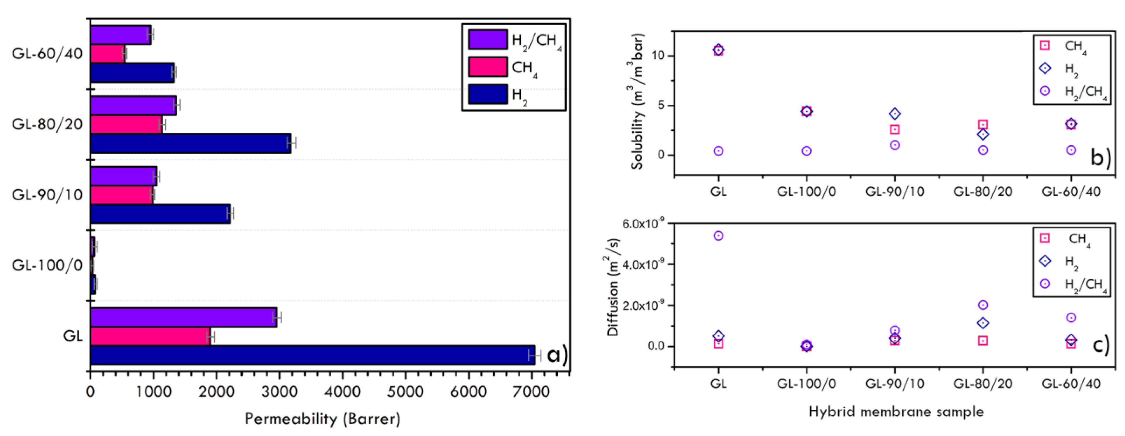
| Samples | Diffusion (m2/s) | Solubility (m3/m3bar) | ||||
|---|---|---|---|---|---|---|
| H2/CH4 | H2 | CH4 | H2/CH4 | H2 | CH4 | |
| GL | 5.39 × 10⁻⁹ | 5.04 × 10⁻¹⁰ | 1.37 × 10⁻¹⁰ | 0.42 | 10.64 | 10.52 |
| GL-100/0 | 1.00 × 10⁻¹⁰ | 1.17 × 10⁻¹¹ | 5.84 × 10⁻¹² | 0.43 | 4.42 | 4.42 |
| GL-90/10 | 7.80 × 10⁻¹⁰ | 4.03 × 10⁻¹⁰ | 2.90 × 10⁻¹⁰ | 1.02 | 4.18 | 2.59 |
| GL-80/20 | 2.02 × 10⁻⁹ | 1.15 × 10⁻⁹ | 2.81 × 10⁻¹⁰ | 0.51 | 2.10 | 3.08 |
| GL-60/40 | 1.40 × 10⁻⁹ | 3.19 × 10⁻¹⁰ | 1.34 × 10⁻¹⁰ | 0.52 | 3.16 | 3.09 |
Disclaimer/Publisher’s Note: The statements, opinions and data contained in all publications are solely those of the individual author(s) and contributor(s) and not of MDPI and/or the editor(s). MDPI and/or the editor(s) disclaim responsibility for any injury to people or property resulting from any ideas, methods, instructions or products referred to in the content. |
© 2023 by the authors. Licensee MDPI, Basel, Switzerland. This article is an open access article distributed under the terms and conditions of the Creative Commons Attribution (CC BY) license (https://creativecommons.org/licenses/by/4.0/).
Share and Cite
Malara, A.; Bonaccorsi, L.; Fotia, A.; Antonucci, P.L.; Frontera, P. Hybrid Fluoro-Based Polymers/Graphite Foil for H2/Natural Gas Separation. Materials 2023, 16, 2105. https://doi.org/10.3390/ma16052105
Malara A, Bonaccorsi L, Fotia A, Antonucci PL, Frontera P. Hybrid Fluoro-Based Polymers/Graphite Foil for H2/Natural Gas Separation. Materials. 2023; 16(5):2105. https://doi.org/10.3390/ma16052105
Chicago/Turabian StyleMalara, Angela, Lucio Bonaccorsi, Antonio Fotia, Pier Luigi Antonucci, and Patrizia Frontera. 2023. "Hybrid Fluoro-Based Polymers/Graphite Foil for H2/Natural Gas Separation" Materials 16, no. 5: 2105. https://doi.org/10.3390/ma16052105