

Morphological, Mechanical and Thermal Properties of Rubber Foams: A Review Based on Recent Investigations

Abstract
:1. Introduction
2. Structural Features
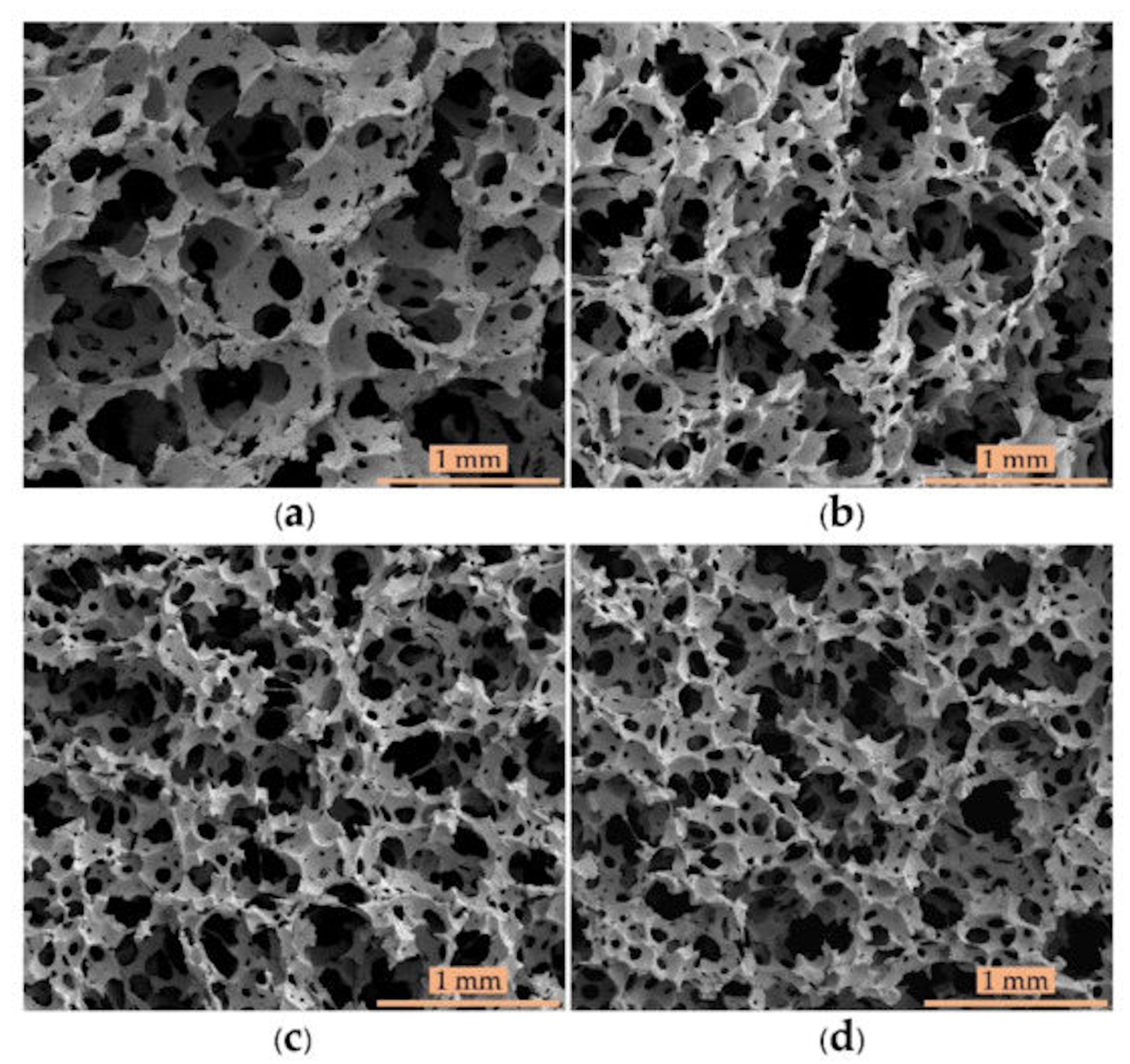
2.1. Porosity: Open or Closed Cell
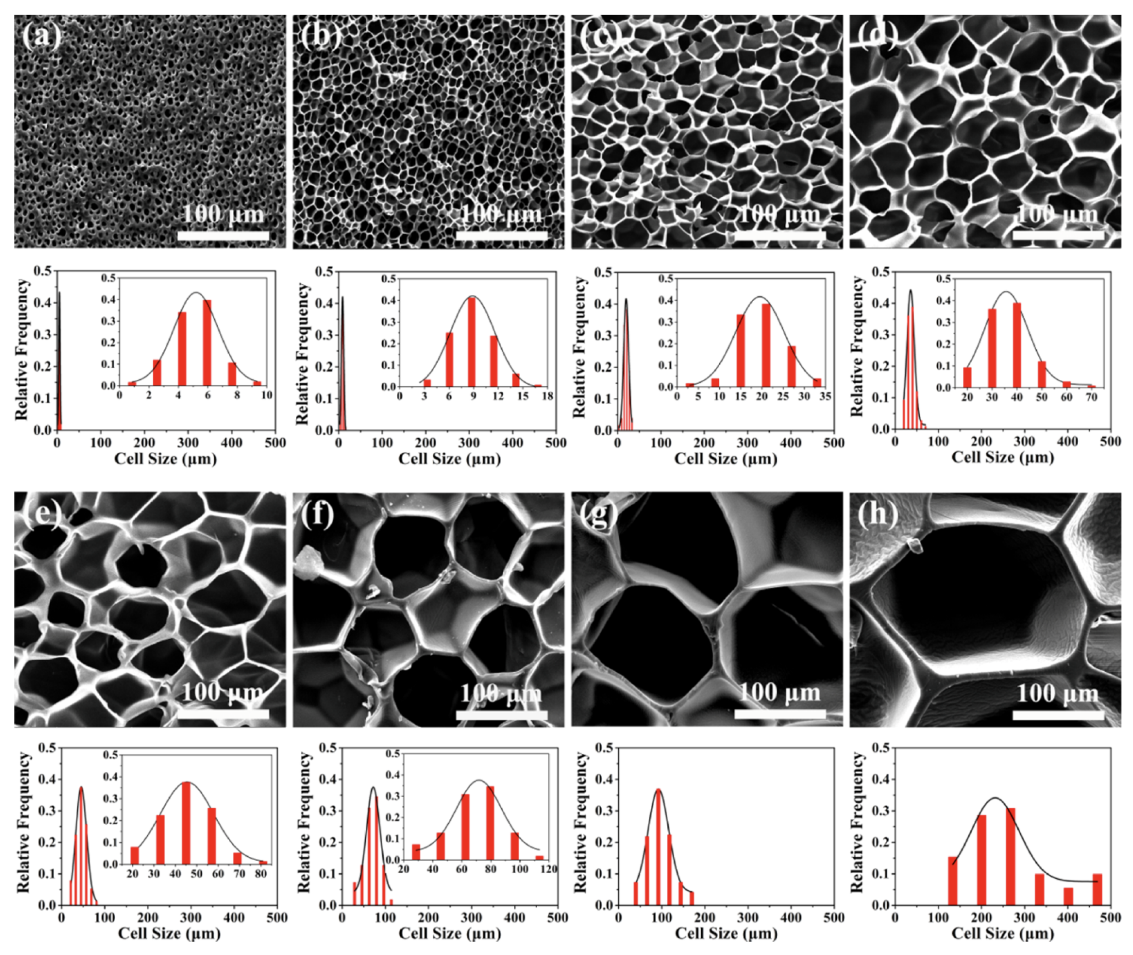
2.2. Cell Size and Cell Density Effect
3. Foaming Process
3.1. Foaming Agents
3.2. Matrix
3.3. Nanofillers
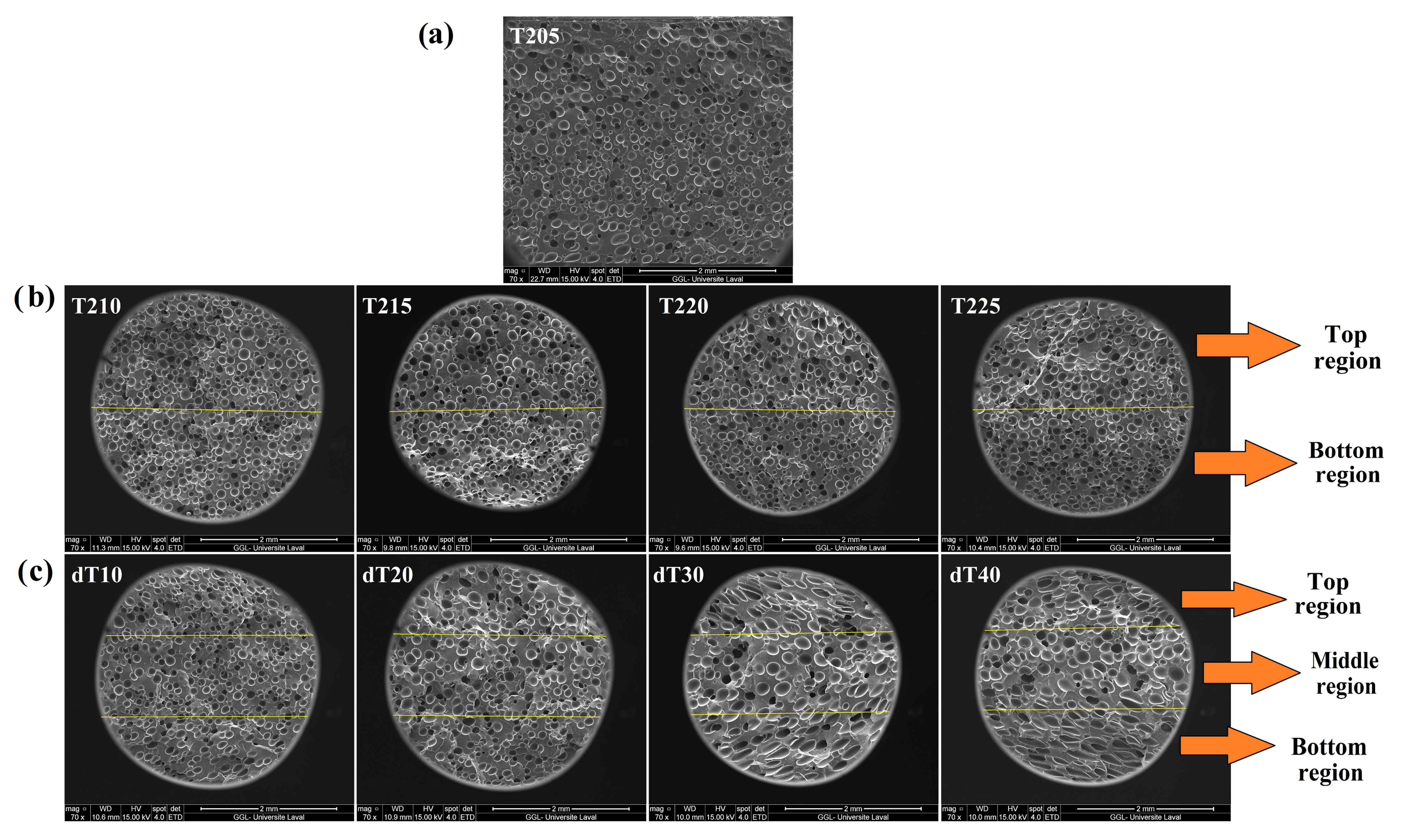
3.4. Foaming and/or Saturation Temperature
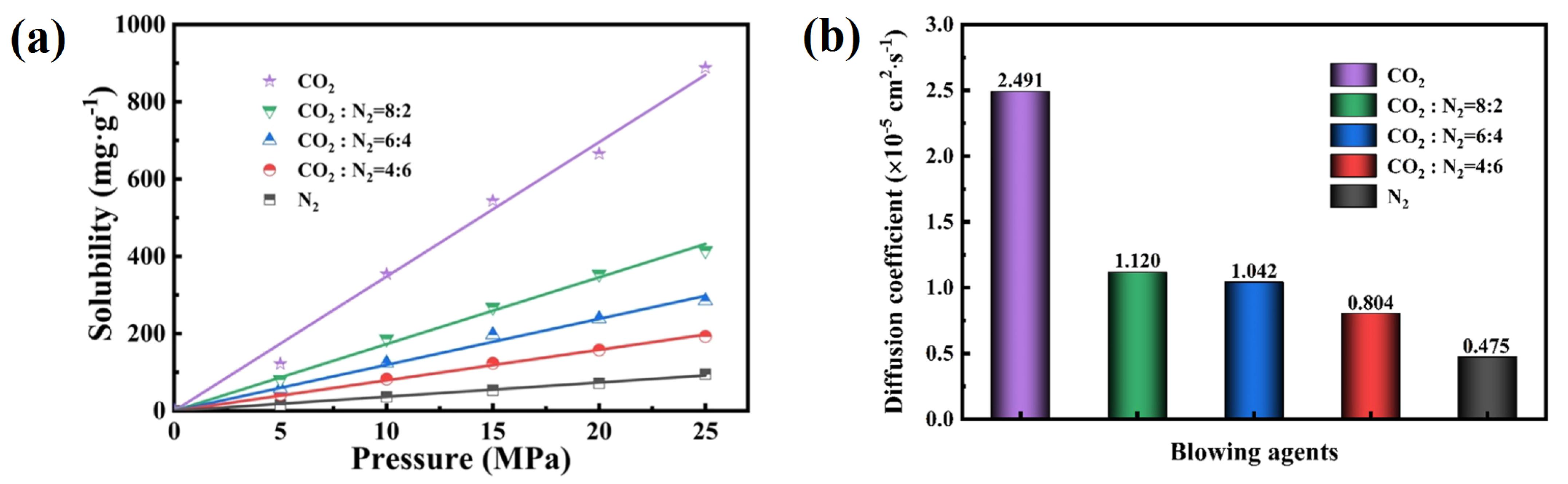
3.5. Foaming and Saturation Pressure
4. Conclusions
4.1. General Conclusions
4.2. Opening for Future Work
Author Contributions
Funding
Institutional Review Board Statement
Informed Consent Statement
Data Availability Statement
Conflicts of Interest
References
- Zhai, W.; Jiang, J.; Park, C.B. A review on physical foaming of thermoplastic and vulcanized elastomers. Polym. Rev. 2022, 62, 95–141. [Google Scholar] [CrossRef]
- Jin, F.-L.; Zhao, M.; Park, M.; Park, S.-J. Recent trends of foaming in polymer processing: A review. Polymers 2019, 11, 953. [Google Scholar] [CrossRef] [PubMed] [Green Version]
- Xie, Z.; Cai, Y.; Zhan, Y.; Meng, Y.; Li, Y.; Xie, Q.; Xia, H. Thermal insulating rubber foams embedded with segregated carbon nanotube networks for electromagnetic shielding applications. Chem. Eng. J. 2022, 435, 135118. [Google Scholar] [CrossRef]
- Zhou, Y.; Tian, Y.; Peng, X. Applications and Challenges of Supercritical Foaming Technology. Polymers 2023, 15, 402. [Google Scholar] [CrossRef] [PubMed]
- Suethao, S.; Ponloa, W.; Phongphanphanee, S.; Wong-Ekkabut, J.; Smitthipong, W. Current challenges in thermodynamic aspects of rubber foam. Sci. Rep. 2021, 11, 6097. [Google Scholar] [CrossRef] [PubMed]
- Rostami-Tapeh-Esmaeil, E.; Vahidifar, A.; Esmizadeh, E.; Rodrigue, D. Chemistry, processing, properties, and applications of rubber foams. Polymers 2021, 13, 1565. [Google Scholar] [CrossRef] [PubMed]
- Frisch, K.C. History of science and technology of polymeric foams. J. Macromol. Sci. Chem. 1981, 15, 1089–1112. [Google Scholar] [CrossRef]
- Mosanenzadeh, S.G.; Naguib, H.E.; Park, C.B.; Atalla, N. Development, characterization, and modeling of environmentally friendly open-cell acoustic foams. Polym. Eng. Sci. 2013, 53, 1979–1989. [Google Scholar] [CrossRef]
- Kong, W.-l.; Bao, J.-B.; Wang, J.; Hu, G.-H.; Xu, Y.; Zhao, L. Preparation of open-cell polymer foams by CO2 assisted foaming of polymer blends. Polymer 2016, 90, 331–341. [Google Scholar] [CrossRef]
- Vahidifar, A.; Esmizadeh, E.; Rostami, E.; Nouri Khorasani, S.; Rodrigue, D. Morphological, rheological, and mechanical properties of hybrid elastomeric foams based on natural rubber, nanoclay, and nanocarbon black. Polym. Compos. 2019, 40, 4289–4299. [Google Scholar] [CrossRef]
- Shojaei-Dindarloo, A.; Karrabi, M.; Hamid, M.; Ghoreishy, R. Various nano-particles influences on structure, viscoelastic, Vulcanization and mechanical behaviour of EPDM nano-composite rubber foam. Plast. Rubber Compos. 2019, 48, 218–225. [Google Scholar] [CrossRef]
- Zonta, E.; Valentini, F.; Dorigato, A.; Fambri, L.; Pegoretti, A. Evaluation of the salt leaching method for the production of ethylene propylene diene monomer rubber foams. Polym. Eng. Sci. 2021, 61, 136–153. [Google Scholar] [CrossRef]
- Pang, Y.; Cao, Y.; Zheng, W.; Park, C.B. A comprehensive review of cell structure variation and general rules for polymer microcellular foams. Chem. Eng. J. 2022, 430, 132662. [Google Scholar] [CrossRef]
- Azdast, T.; Hasanzadeh, R. Increasing cell density/decreasing cell size to produce microcellular and nanocellular thermoplastic foams: A review. J. Cell. Plast. 2021, 57, 769–797. [Google Scholar] [CrossRef]
- Rostami-Tapeh-Esmaeil, E.; Shojaei, S.; Rodrigue, D. Mechanical and Thermal Properties of Functionally Graded Polyolefin Elastomer Foams. Polymers 2022, 14, 4124. [Google Scholar] [CrossRef] [PubMed]
- Tang, W.; Liao, X.; Zhang, Y.; Li, J.; Wang, G.; Li, G. Mechanical–microstructure relationship and cellular failure mechanism of silicone rubber foam by the cell microstructure designed in supercritical CO2. J. Phys. Chem. C 2019, 123, 26947–26956. [Google Scholar] [CrossRef]
- Syahrin, S.; Zunaida, Z.; Hakimah, O.; Nuraqmar, S. Effect of blowing agent on compression and morphological properties of natural rubber latex foam. AIP Conf. Proc. 2020, 2267, 020037. [Google Scholar] [CrossRef]
- Jia, F.; Liu, C.; Yang, B.; Lee, A.; Wu, L.; Ning, H. Preparation of Novel Graphene/Silicone Rubber Nanocomposite Dielectric Foams. Polymers 2022, 14, 3273. [Google Scholar] [CrossRef] [PubMed]
- Vahidifar, A.; Esmizadeh, E.; Rodrigue, D. Effect of the simultaneous curing and foaming kinetics on the morphology development of polyisoprene closed cell foams. Elastomery 2018, 22, 3–18. [Google Scholar]
- Standau, T.; Altstädt, V. Foams. In Polypropylene Handbook; Springer: Cham, Switzerland, 2019; pp. 579–641. [Google Scholar]
- Marl, S.; Giesen, R.-U.; Heim, H.-P. Liquid silicone rubber foamed with thermoplastic expandable microspheres. Materials 2022, 15, 3779. [Google Scholar] [CrossRef] [PubMed]
- Ryzhenkov, A.V.; Pogorelov, S.I.; Loginova, N.A.; Belyaeva, E.V.; Plestsheva, A.Y. Syntactic foams efficiency with the use of various microspheres for heat supply equipment and pipelines heat insulation. Mod. Appl. Sci. 2015, 9, 319. [Google Scholar] [CrossRef] [Green Version]
- Valentini, F.; Dorigato, A.; Fambri, L.; Pegoretti, A. Novel EPDM/paraffin foams for thermal energy storage applications. Rubber Chem. Technol. 2021, 94, 432–448. [Google Scholar] [CrossRef]
- Bianchi, M.; Valentini, F.; Fredi, G.; Dorigato, A.; Pegoretti, A. Thermo-mechanical behavior of novel EPDM foams containing a phase change material for thermal energy storage applications. Polymers 2022, 14, 4058. [Google Scholar] [CrossRef] [PubMed]
- Jin, D.; Xiao, K.; Han, Y.; Xiang, G.; Zhou, Z.; Wang, J. A preparation method of porous surface nitrile butadiene rubber with low friction coefficient under water lubrication condition by salt leaching. J. Appl. Polym. Sci. 2021, 138, 50555. [Google Scholar] [CrossRef]
- Peng, L.; Lei, L.; Liu, Y.; Du, L. Improved mechanical and sound absorption properties of open cell silicone rubber foam with NaCl as the pore-forming agent. Materials 2021, 14, 195. [Google Scholar] [CrossRef] [PubMed]
- Yaqoob, A.A.; Ibrahim, M.N.M.; Umar, K.; Ahmad, A. Applications of Supercritical Carbon Dioxide in the Rubber Industry. In Advanced Nanotechnology and Application of Supercritical Fluids; Springer: Cham, Switzerland, 2020; pp. 199–218. [Google Scholar]
- Zhang, W.; Deng, Z.; Yuan, H.; Luo, S.; Wen, H.; Liu, T. Preparation and properties of silicone rubber materials with foam/solid alternating multilayered structures. Polym. J. 2021, 53, 619–631. [Google Scholar] [CrossRef]
- Jacobs, M.A.; Kemmere, M.F.; Keurentjes, J.T. Foam processing of poly (ethylene-co-vinyl acetate) rubber using supercritical carbon dioxide. Polymer 2004, 45, 7539–7547. [Google Scholar] [CrossRef]
- Tessanan, W.; Phinyocheep, P.; Daniel, P.; Gibaud, A. Microcellular natural rubber using supercritical CO2 technology. J. Supercrit. Fluids 2019, 149, 70–78. [Google Scholar] [CrossRef]
- Coste, G.; Negrell, C.; Caillol, S. From gas release to foam synthesis, the second breath of blowing agents. Eur. Polym. J. 2020, 140, 110029. [Google Scholar] [CrossRef]
- Suethao, S.; Phongphanphanee, S.; Wong-Ekkabut, J.; Smitthipong, W. The relationship between the morphology and elasticity of natural rubber foam based on the concentration of the chemical blowing agent. Polymers 2021, 13, 1091. [Google Scholar] [CrossRef]
- Afrinaldi, B.; Vicarneltor, D.N.; Rudianto, R.P.; Hakim, A.R.; Muslim, O.F. Influence of Zinc Oxide Addition on Azodicarbonamide Thermal Decomposition in the Polyethylene/Ethylene Vinyl Acetate Foaming Release. Mater. Sci. Forum. Trans. Tech. Pub. 2021, 1028, 234–239. [Google Scholar] [CrossRef]
- Heidari, A.; Fasihi, M. Cell structure-impact property relationship of polypropylene/thermoplastic elastomer blend foams. Express Polym. Lett. 2019, 13, 429–442. [Google Scholar] [CrossRef]
- Kmetty, Á.; Litauszki, K.; Réti, D. Characterization of different chemical blowing agents and their applicability to produce poly (lactic acid) foams by extrusion. Appl. Sci. 2018, 8, 1960. [Google Scholar] [CrossRef] [Green Version]
- Mao, Y.; Qi, R. Preparation of polyethylene–octene elastomer foams by compression molding. J. Appl. Polym. Sci. 2008, 109, 3249–3255. [Google Scholar] [CrossRef]
- Salmazo, L.O.; Lopéz-Gil, A.; Ariff, Z.M.; Rodriguez-Mendez, M.L.; Job, A.E.; Rodriguez-Perez, M.A. Study of the foaming kinetics in epoxidized natural rubber foams crosslinked by electron beam irradiation. Macromol. Chem. Phys. 2018, 219, 1800295. [Google Scholar] [CrossRef]
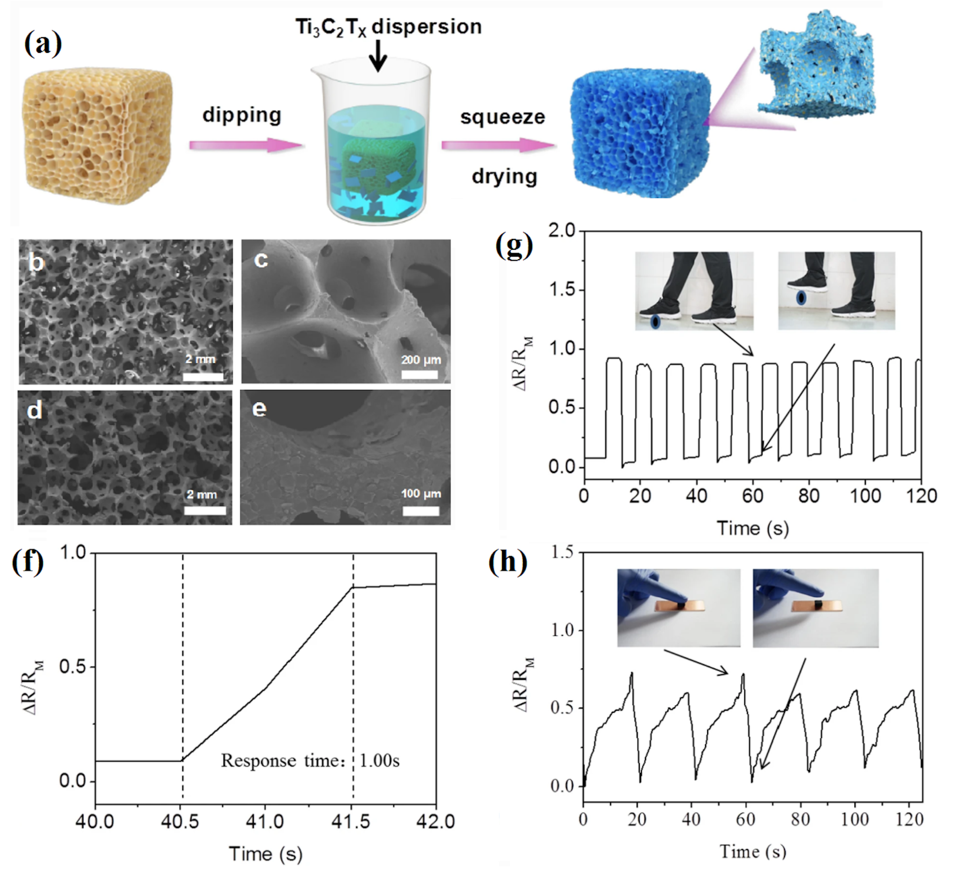
- Ding, H.; Luo, Z.; Kong, N.; Li, Z.; Zhao, P.; Zhang, J.; Tao, J. Constructing conductive titanium carbide nanosheet (MXene) network on natural rubber foam framework for flexible strain sensor. J. Mater. Sci. Mater. Electron. 2022, 33, 15563–15573. [Google Scholar] [CrossRef]
- Lee, K.; Chang, Y.W.; Kim, S.W. Ethylene–propylene-diene terpolymer/halloysite nanocomposites: Thermal, mechanical properties, and foam processing. J. Appl. Polym. Sci. 2014, 131, 40307. [Google Scholar] [CrossRef]
- Shao, L.; Ji, Z.-Y.; Ma, J.-Z.; Xue, C.-H.; Ma, Z.-L.; Zhang, J. The synergy of double cross-linking agents on the properties of styrene butadiene rubber foams. Sci. Rep. 2016, 6, 36931. [Google Scholar] [CrossRef] [PubMed] [Green Version]
- Bahadar, A.; Zwawi, M. Development of SWCNTs-reinforced EPDM/SBR matrices for shock absorbing applications. Mater. Res. Express 2020, 7, 025310. [Google Scholar] [CrossRef]
- Park, K.W.; Ray Chowdhury, S.; Park, C.C.; Kim, G.H. Effect of dispersion state of organoclay on cellular foam structure and mechanical properties of ethylene vinyl acetate copolymer/ethylene-1-butenecopolymer/organoclay nanocomposite foams. J. Appl. Polym. Sci. 2007, 104, 3879–3885. [Google Scholar] [CrossRef]
- Kim, M.S.; Park, C.C.; Chowdhury, S.R.; Kim, G.H. Physical properties of ethylene vinyl acetate copolymer (EVA)/natural rubber (NR) blend based foam. J. Appl. Polym. Sci. 2004, 94, 2212–2216. [Google Scholar] [CrossRef]
- Zhang, B.S.; Zhang, Z.X.; Lv, X.F.; Lu, B.X.; Xin, Z.X. Properties of chlorinated polyethylene rubber/ethylene vinyl acetate copolymer blend-based foam. Polym. Eng. Sci. 2012, 52, 218–224. [Google Scholar] [CrossRef]
- Liao, X.; Xu, H.; Li, S.; Zhou, C.; Li, G.; Park, C.B. The effects of viscoelastic properties on the cellular morphology of silicone rubber foams generated by supercritical carbon dioxide. RSC Adv. 2015, 5, 106981–106988. [Google Scholar] [CrossRef]
- Luo, S.K.; Ding, G.F.; Dai, B.; Yang, M.; Liu, F. Study on the cell structure and mechanical properties of methyl vinyl silicone rubber foam materials. Adv. Mater. Res. 2014, 1004, 297–306. [Google Scholar] [CrossRef]
- Rostami-Tapeh-Esmaeil, E.; Heydari, A.; Vahidifar, A.; Esmizadeh, E.; Rodrigue, D. Experimental and Finite Element Simulation of Polyolefin Elastomer Foams Using Real 3D Structures: Effect of Foaming Agent Content. Polymers 2022, 14, 4692. [Google Scholar] [CrossRef]
- Shojaie, S.; Vahidifar, A.; Naderi, G.; Shokri, E.; Mekonnen, T.H.; Esmizadeh, E. Physical Hybrid of Nanographene/Carbon Nanotubes as Reinforcing Agents of NR-Based Rubber Foam. Polymers 2021, 13, 2346. [Google Scholar] [CrossRef]
- Afolabi, L.O.; Ariff, Z.M.; Hashim, S.F.S.; Alomayri, T.; Mahzan, S.; Kamarudin, K.-A.; Muhammad, I.D. Syntactic foams formulations, production techniques, and industry applications: A review. J. Mater. Res. Technol. 2020, 9, 10698–10718. [Google Scholar] [CrossRef]
- Esmizadeh, E.; Vahidifar, A.; Rostami, E.; Nouri Khorasani, S.; Ghayoumi, M.; Khonakdar, H.A. Effect of carbon black on morphological and mechanical properties of rubber foams produced by a single-step method. J. Appl. Res. Chem. Polym.Eng. 2017, 1, 49–60. [Google Scholar]
- Shao, Y.; Luo, C.; Deng, B.-w.; Yin, B.; Yang, M.-b. Flexible porous silicone rubber-nanofiber nanocomposites generated by supercritical carbon dioxide foaming for harvesting mechanical energy. Nano Energy 2020, 67, 104290. [Google Scholar] [CrossRef]
- Leblanc, J.L. Rubber–filler interactions and rheological properties in filled compounds. Prog. Polym. Sci. 2002, 27, 627–687. [Google Scholar] [CrossRef]
- Ponnamma, D.; Sadasivuni, K.K.; Strankowski, M.; Guo, Q.; Thomas, S. Synergistic effect of multi walled carbon nanotubes and reduced graphene oxides in natural rubber for sensing application. Soft Matter 2013, 9, 10343–10353. [Google Scholar] [CrossRef]
- Bashir, M.A.; Iqbal, N.; Shahid, M.; Ahmed, R. Structural, viscoelastic, and vulcanization study of sponge ethylene–propylene–diene monomer composites with various carbon black loadings. J. Appl. Polym. Sci. 2014, 131, 39423. [Google Scholar] [CrossRef]
- Xiang, B.; Deng, Z.; Zhang, F.; Wen, N.; Lei, Y.; Liu, T.; Luo, S. Microcellular silicone rubber foams: The influence of reinforcing agent on cellular morphology and nucleation. Polym. Eng. Sci. 2019, 59, 5–14. [Google Scholar] [CrossRef] [Green Version]
- Pongmuksuwan, P.; Salayong, K.; Lertwiriyaprapa, T.; Kitisatorn, W. Electromagnetic absorption and mechanical properties of natural rubber composites based on conductive carbon black and Fe3O4. Materials 2022, 15, 6532. [Google Scholar] [CrossRef]
- Phomrak, S.; Nimpaiboon, A.; Newby, B.-M.Z.; Phisalaphong, M. Natural rubber latex foam reinforced with micro-and nanofibrillated cellulose via Dunlop method. Polymers 2020, 12, 1959. [Google Scholar] [CrossRef]
- Prasopdee, T.; Smitthipong, W. Effect of fillers on the recovery of rubber foam: From theory to applications. Polymers 2020, 12, 2745. [Google Scholar] [CrossRef] [PubMed]
- Prasopdee, T.; Shah, D.U.; Smitthipong, W. Approaches toward high resilience rubber foams: Morphology–mechanics–thermodynamics relationships. Macromol. Mater. Eng. 2021, 306, 2100337. [Google Scholar] [CrossRef]
- Sombatsompop, N. Analysis of cure characteristics on cross-link density and type, and viscoelastic properties of natural rubber. Polym. Plast. Technol. Eng. 1998, 37, 333–349. [Google Scholar] [CrossRef]
- Kim, J.-H.; Koh, J.-S.; Choi, K.-C.; Yoon, J.-M.; Kim, S.-Y. Effects of foaming temperature and carbon black content on the cure characteristics and mechanical properties of natural rubber foams. J. Indust. Eng. Chem. 2007, 13, 198–205. [Google Scholar]
- Najib, N.; Ariff, Z.; Bakar, A.; Sipaut, C. Correlation between the acoustic and dynamic mechanical properties of natural rubber foam: Effect of foaming temperature. Mater. Des. 2011, 32, 505–511. [Google Scholar] [CrossRef]
- Pechurai, W.; Muansupan, T.; Seawlee, P. Effect of foaming temperature and blowing agent content on cure characteristics, mechanical and morphological properties of natural rubber foams. Adv. Mater. Res. 2014, 844, 454–457. [Google Scholar] [CrossRef]
- Kim, J.-H.; Choi, K.-C.; Yoon, J.-M. The foaming characteristics and physical properties of natural rubber foams: Effects of carbon black content and foaming pressure. J. Indust. Eng. Chem. 2006, 12, 795–801. [Google Scholar]
- Yang, Q.; Yu, H.; Song, L.; Lei, Y.; Zhang, F.; Lu, A.; Liu, T.; Luo, S. Solid-state microcellular high temperature vulcanized (HTV) silicone rubber foam with carbon dioxide. J. Appl. Polym. Sci. 2017, 134, 44807. [Google Scholar] [CrossRef] [Green Version]
- Wang, B.; Liao, X.; Tang, W.; Li, S.; Jiang, Q.; Yang, J.; Li, J.; Li, R.; Tian, C.; Li, G. Cellular structure design by controlling the dissolution and diffusion behavior of gases in silicon rubber. J. Supercrit. Fluids 2022, 186, 105610. [Google Scholar] [CrossRef]
- Zhu, J.; Li, X.; Weng, Y.; Tan, B.; Zhang, S. Fabrication of microcellular epoxidized natural rubber foam with superior ductility by designable chemical and physical crosslinking networks. J. Supercrit. Fluids 2022, 181, 105508. [Google Scholar] [CrossRef]


| Sample Name | Average Cell Size (μm) | Cell Density (Cells/cm3) |
|---|---|---|
| NRF (unfilled) | 836 | 3041 |
| NRF/2 Ch | 860 | 2778 |
| NRF/4 Ch | 988 | 1807 |
| NRF/6 Ch | 1081 | 1379 |
| NRF/8 Ch | 1092 | 1333 |
| NRF/2 Si | 1079 | 1412 |
| NRF/2 Si | 909 | 2316 |
| NRF/2 Si | 876 | 2546 |
| NRF/2 Si | 673 | 5606 |
| Matrix | Foaming Agent | Filler | Foaming Process | Density (g/cm3) | Morphology | Reference |
|---|---|---|---|---|---|---|
| NR | ADC (4 phr) | NC (0–10 phr) | T (155 °C) P (50 bar) t (30 min) * | 0.40 | Closed cell CS (340–143 μm) CD (35–225 cells/mm3) ** | [10] |
| EPDM | OBSH (3 phr) | CNT (1–3 phr) NC (2–6 phr) | T (160 °C) P (50 bar) t (20 min) | Closed/open cell CD (5.21 × 10¹⁰–6.28×10¹⁰ cells/cm3) | [11] | |
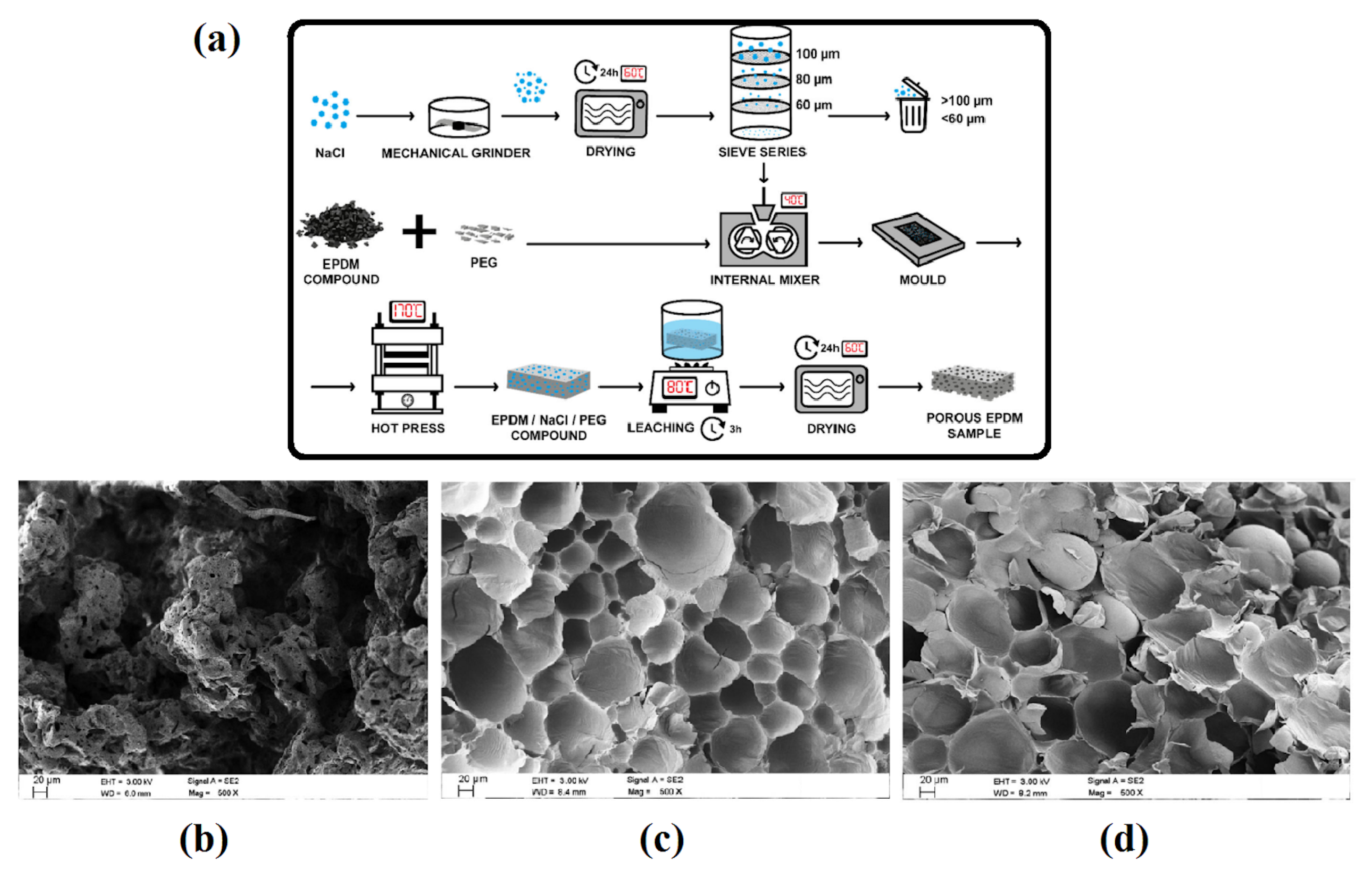
| EPDM | Micropearl (14 phr) Expancel (14 phr) Sodium chloride (305 phr) | CB (20 phr) | T (170 °C) P (2 bar) t (20 min) | 0.23–0.42 | Closed/open cell CS (60–80 μm) | [12] |
| POE | ADC (4 phr) | Tavg (205–215 °C) ΔT (0–40 °C) P (8.5 bar) T (12 min) | 0.55–0.72 | Closed cell CS (98–337 μm) CD (204–820 cells/mm3) | [15] | |
| SR | scCO2 | Silica (26 wt.%) | T (40–70 °C) P (10–15 MPa) t (1 h) | 0.25–0.70 | Closed cell CS (5–266 μm) CD (2.60 × 10⁵–5.60 × 10⁹ cells/cm3) | [16] |
| NR | NaHCO3 (3 to 12 phr) | T (150 °C) t (45 min) | Closed cell CS (420–620 μm) | [17] | ||
| SR | NG (1–4 wt.%) | T (60 °C) t (1 h) | Closed/open cell CS (191.00–79.40 μm) CD (2.13 × 10⁵–7.15 × 10⁵ cells/cm3) | [18] | ||
| EPDM | Expancel (14 phr) | T (170 °C) P (2 bar) t (10 min) | 0.48–0.59 | Closed cell CS (20 μm) | [23] | |
| EPDM | Hostatron (1.3 phr) | T (170 °C) P (2 bar) t (10 min) | 0.57–0.73 | Closed cell CS (100 μm) | [23] | |
| SR | NaCl (0–100 phr) | T (150 °C) t (20 min) | 0.44–0.63 | Close/open cell CS (100–300 μm) | [26] | |
| NR | PO (0–45%) | T (90 °C) t (2 h) | 0.11–0.12 | Open cell CS (273–548 μm) CD (10,241–82,450 cells/cm3) | [32] | |
| POE | ADC (1–13 phr) | T (170 °C) P (10 MPa) t (10 min) | 0.06–0.82 | Closed cell CD (3.79 × 10⁹–6.29 × 10¹⁰ cells/cm3) | [36] | |
| NR | ADC (10 phr) | Electron beam irradiation (50–150 kGy) t (30–90 s) | Closed cell CS (22.60–74.72 μm) CD (4.92 × 10⁵–249.60 × 10⁵ cells/cm3) | [37] | ||
| ENR | ADC (10 phr) | Electron beam irradiation (50–150 kGy) t (30–90 s) | Closed cell CS (6.83–74.57 μm) CD (4.19 × 10⁵–1975.20 × 105 cells/cm3) | [37] | ||
| EPDM | scCO2 | HNT (0–10 phr) | T (130 °C) P (30 MPa) t (24 h) | 0.23–0.35 | Closed cell CS (7.80–12.00 µm) CD (4.21 × 10⁹–1.54 × 10¹⁰ cells/cm3) | [39] |
| SBR | ADC (3 phr) | T (200 °C) | 0.22–0.83 | Closed/open cell CS (7.68–22.94 μm) | [40] | |
| SR | scCO2 | Silica (30–50 phr) | T (40−80 °C) P (10−14 MPa) t (1 h) | Closed/open cell CS (4.24–77.10 µm) CD (0.40 × 10⁶–1.40 × 10⁹ cells/cm3) | [45] | |
| POE | ADC (2–5 phr) | T (205 °C) P (8.5 MPa) t (12 min) | 0.61–0.75 | Closed cell CS (109.40–153.10 µm) CD (103–591 cells/mm3) | [47] | |
| NR | ADC (6 phr) | CNT/NG (0–2 phr) | T (160 °C) | Closed cell CS (80–800 μm) | [48] | |
| SR | scCO2 | Silica (40–70 phr) | T (50–80 °C) P (16–22 MPa) t (1 h) | Closed cell CS (0.71–4.60 µm) CD (0.40 × 10¹⁰–1.02 × 10¹¹ cells/cm3) | [55] | |
| NR | PO (1.5 phr) | Microcellulose/nanocellulose (5–20 phr) | T (100 °C) t (1 h) | 0.15–0.31 | Open cell (10–500 μm) | [57] |
| NR | PO (3.63%) | Cs (4–12 phr) | T (90 °C) t (2 h) | 0.069–0.071 | Open cell CS (0.54–0.52 μm) CD (11,540–12,319 cells/cm3) | [59] |
| ENR | scCO2 | T (35 °C) P (15–25 MPa) t (1 h) | Closed cell CS(1.30–1.70 µm) CD (1.10 × 10¹¹–1.40 × 10¹¹ cells/cm3) | [67] | ||
| ENR | scCO2 | T (35–75 °C) P (15 MPa) t (1 h) | Closed cell CS (1.70–5.50 µm) CD (8.40 × 10⁹–1.10 × 10¹¹ cells/cm3) | [67] |
Disclaimer/Publisher’s Note: The statements, opinions and data contained in all publications are solely those of the individual author(s) and contributor(s) and not of MDPI and/or the editor(s). MDPI and/or the editor(s) disclaim responsibility for any injury to people or property resulting from any ideas, methods, instructions or products referred to in the content. |
© 2023 by the authors. Licensee MDPI, Basel, Switzerland. This article is an open access article distributed under the terms and conditions of the Creative Commons Attribution (CC BY) license (https://creativecommons.org/licenses/by/4.0/).
Share and Cite
Rostami-Tapeh-Esmaeil, E.; Rodrigue, D. Morphological, Mechanical and Thermal Properties of Rubber Foams: A Review Based on Recent Investigations. Materials 2023, 16, 1934. https://doi.org/10.3390/ma16051934
Rostami-Tapeh-Esmaeil E, Rodrigue D. Morphological, Mechanical and Thermal Properties of Rubber Foams: A Review Based on Recent Investigations. Materials. 2023; 16(5):1934. https://doi.org/10.3390/ma16051934
Chicago/Turabian StyleRostami-Tapeh-Esmaeil, Ehsan, and Denis Rodrigue. 2023. "Morphological, Mechanical and Thermal Properties of Rubber Foams: A Review Based on Recent Investigations" Materials 16, no. 5: 1934. https://doi.org/10.3390/ma16051934