
Doping Engineering for Optimizing Piezoelectric and Elastic Performance of AlN

Abstract
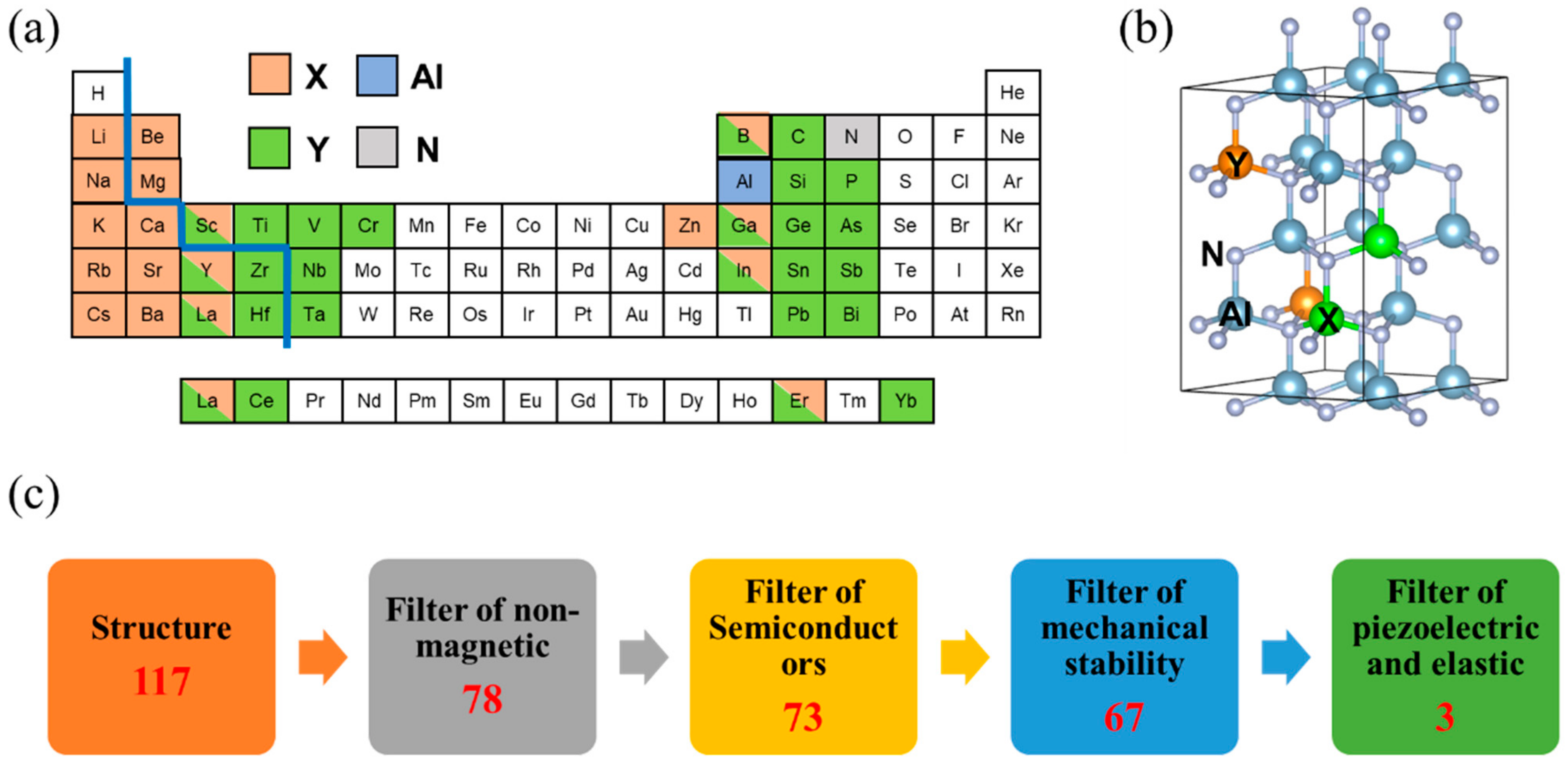
:1. Introduction
2. Computational Details
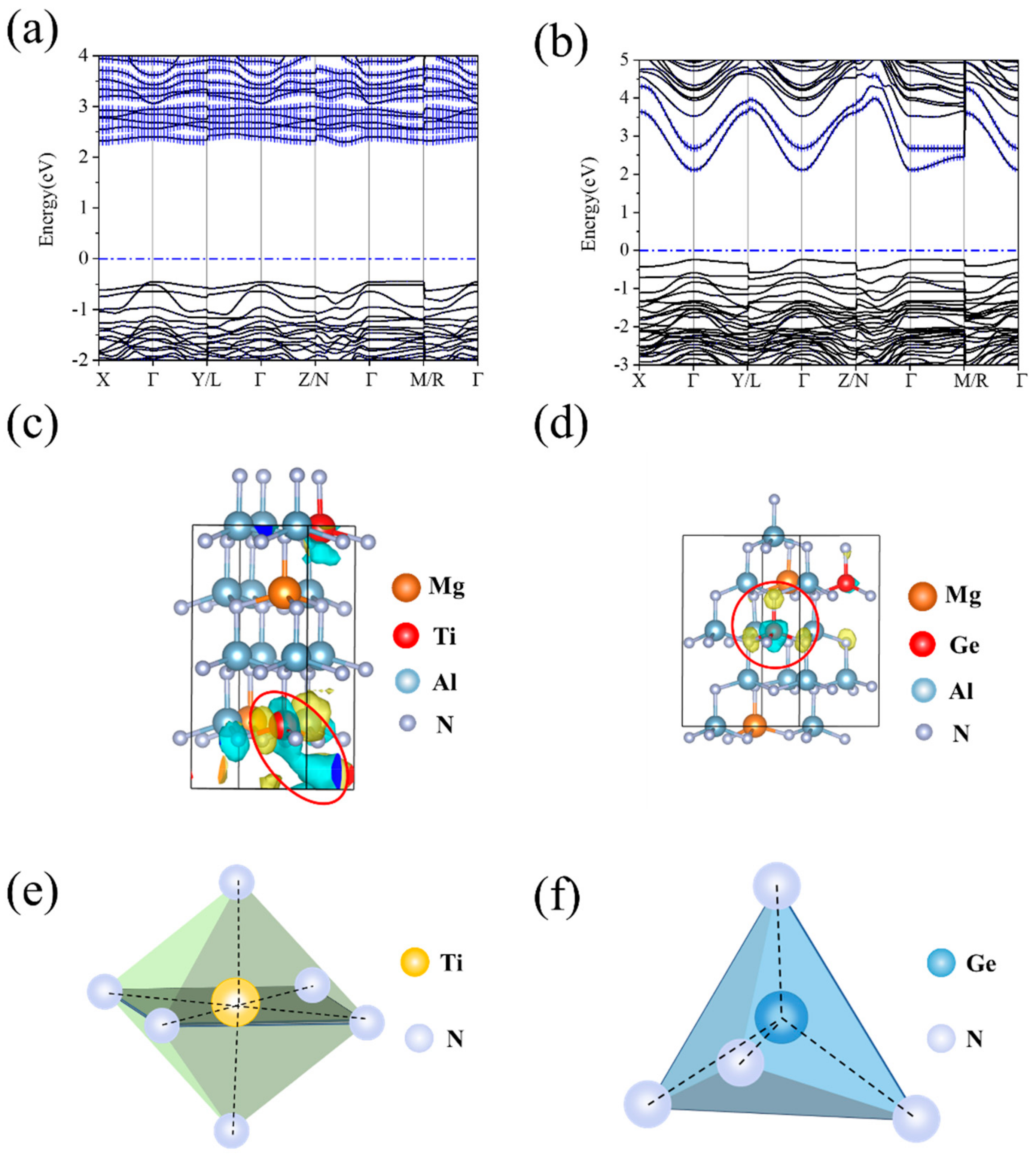
3. Results
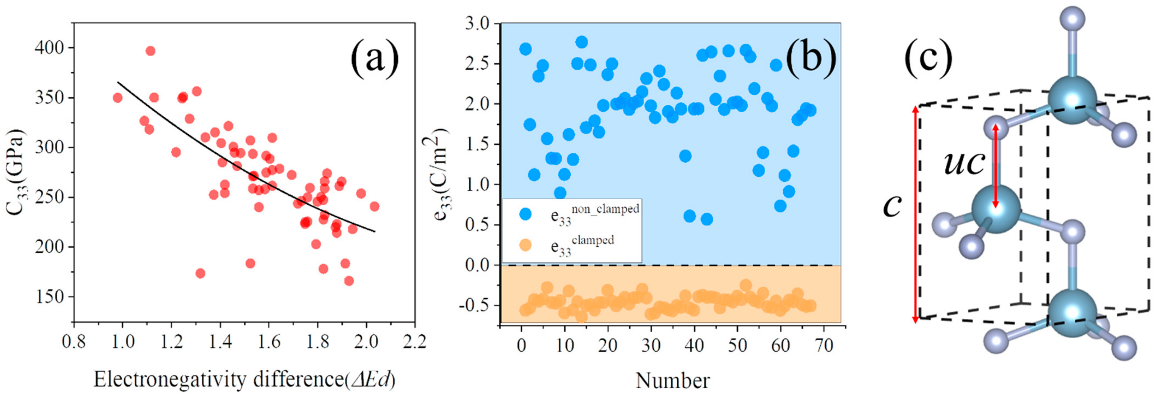
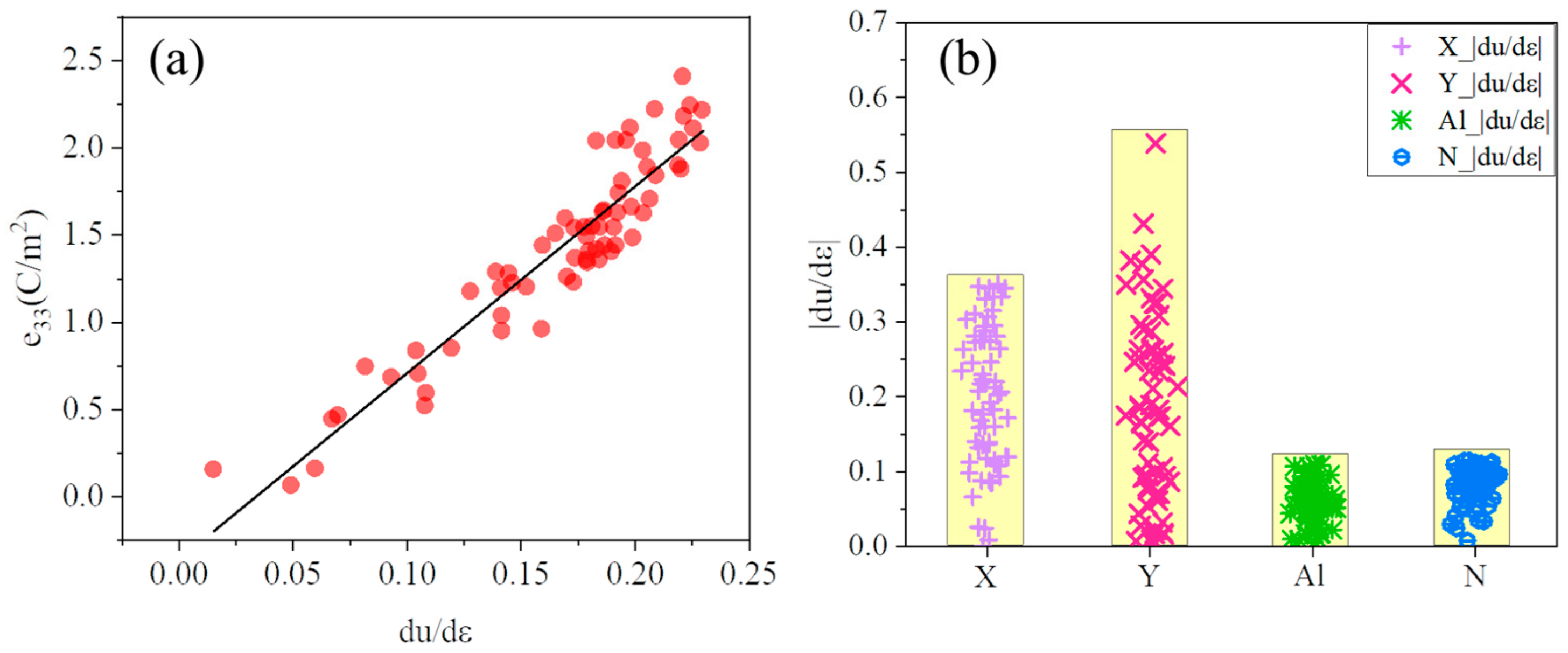
4. Discussion
4.1. Analysis of Elastic Properties
4.2. Analysis of Piezoelectric Properties
5. Conclusions
Supplementary Materials
Author Contributions
Funding
Institutional Review Board Statement
Informed Consent Statement
Data Availability Statement
Acknowledgments
Conflicts of Interest
References
- Ruby, R. A Snapshot in Time: The Future in Filters for Cell Phones. IEEE Microw. Mag. 2015, 16, 46–59. [Google Scholar] [CrossRef]
- Gillenwater, T. Evolution of the Smartphone. Microw. J. 2017, 60, 40–52. [Google Scholar]
- Hickman, A.L.; Chaudhuri, R.; Bader, S.J.; Nomoto, K.; Li, L.; Hwang, J.; Xing, H.G.; Jena, D. Next Generation Electronics on the Ultrawide-Bandgap Aluminum Nitride Platform. Semicond. Sci. Technol. 2021, 36, 044001. [Google Scholar] [CrossRef]
- Weigel, R.; Morgan, D.P.; Owens, J.M.; Ballato, A.; Lakin, K.M.; Hashimoto, K.; Ruppel, C.C.W. Microwave Acoustic Materials, Devices, and Applications. IEEE Trans. Microw. Theory Tech. 2002, 50, 738–749. [Google Scholar] [CrossRef]
- Fu, Y.Q.; Luo, J.K.; Nguyen, N.T.; Walton, A.J.; Flewitt, A.J.; Zu, X.T.; Li, Y.; McHale, G.; Matthews, A.; Iborra, E.; et al. Advances in Piezoelectric Thin Films for Acoustic Biosensors, Acoustofluidics and Lab-on-Chip Applications. Prog. Mater. Sci. 2017, 89, 31–91. [Google Scholar] [CrossRef] [Green Version]
- Fei, C.; Liu, X.; Zhu, B.; Li, D.; Yang, X.; Yang, Y.; Zhou, Q. AlN Piezoelectric Thin Films for Energy Harvesting and Acoustic Devices. Nano Energy 2018, 51, 146–161. [Google Scholar] [CrossRef]
- Qin, L.; Chen, Q.; Cheng, H.; Chen, Q.; Li, J.-F.; Wang, Q.-M. Viscosity Sensor Using ZnO and AlN Thin Film Bulk Acoustic Resonators with Tilted Polar C-Axis Orientations. J. Appl. Phys. 2011, 110, 094511. [Google Scholar] [CrossRef]
- Aigner, R. MEMS in RF-Filter Applications: Thin Film Bulk-Acoustic-Wave Technology. In Proceedings of the The 13th Interna-tional Conference on Solid-State Sensors, Actuators and Microsystems, Seoul, Republic of Korea, 5–9 June 2005; Volume 1, pp. 5–8, Digest of Technical Papers. TRANSDUCERS ’05. [Google Scholar]
- Signore, M.A.; Rescio, G.; Pascali, C.D.; Iacovacci, V.; Francioso, L. Fabrication and Characterization of AlN-Based Flexible Piezoelectric Pressure Sensor Integrated into an Implantable Artificial Pancreas. Sci. Rep. 2019, 9, 17130. [Google Scholar] [CrossRef] [Green Version]
- Lefeuvre, E.; Badel, A.; Richard, C.; Petit, L.; Guyomar, D. A Comparison between Several Vibration-Powered Piezoelectric Generators for Standalone Systems. Sens. Actuator A-Phys. 2006, 126, 405–416. [Google Scholar] [CrossRef]
- Lanz, R. Piezoelectric Thin Films for Bulk Acoustic Wave Resonator Applications: From Processing to Microwave Filters; EPFL: Lausanne, Switzerland, 2004. [Google Scholar] [CrossRef]
- Rughoobur, G. In-Liquid Bulk Acoustic Wave Resonators for Biosensing Applications. Ph.D. Thesis, University of Cambridge, Cambridge, UK, 2017. [Google Scholar]
- Hashimoto, K. RF Bulk Acoustic Wave Filters for Communications; Artech House: London, UK, 2009. [Google Scholar]
- Tasnádi, F.; Alling, B.; Höglund, C.; Wingqvist, G.; Birch, J.; Hultman, L.; Abrikosov, I.A. Origin of the Anomalous Piezoelectric Response in Wurtzite ScxAl1−XN Alloys. Phys. Rev. Lett. 2010, 104, 137601. [Google Scholar] [CrossRef] [Green Version]
- Akiyama, M.; Kamohara, T.; Kano, K.; Teshigahara, A.; Takeuchi, Y.; Kawahara, N. Enhancement of Piezoelectric Response in Scandium Aluminum Nitride Alloy Thin Films Prepared by Dual Reactive Cosputtering. Adv. Mater. 2009, 21, 593–596. [Google Scholar] [CrossRef]
- Manna, S.; Talley, K.R.; Gorai, P.; Mangum, J.; Zakutayev, A.; Brennecka, G.L.; Stevanović, V.; Ciobanu, C.V. Enhanced Piezoelectric Response of AlN via CrN Alloying. Phys. Rev. Appl. 2018, 9, 034026. [Google Scholar] [CrossRef] [Green Version]
- Tholander, C.; Abrikosov, I.A.; Hultman, L.; Tasnádi, F. Volume Matching Condition to Establish the Enhanced Piezoelectricity in Ternary (Sc,Y) 0.5 (Al,Ga,In) 0.5 N Alloys. Phys. Rev. B 2013, 87, 094107. [Google Scholar] [CrossRef] [Green Version]
- Noor-A-Alam, M.; Olszewski, O.Z.; Campanella, H.; Nolan, M. Large Piezoelectric Response and Ferroelectricity in Li and V/Nb/Ta Co-Doped w-AlN. ACS Appl. Mater. Interfaces 2021, 13, 944–954. [Google Scholar] [CrossRef]
- Hirata, K.; Yamada, H.; Uehara, M.; Anggraini, S.A.; Akiyama, M. First-Principles Study of Piezoelectric Properties and Bonding Analysis in (Mg, X, Al)N Solid Solutions (X = Nb, Ti, Zr, Hf). ACS Omega 2019, 4, 15081–15086. [Google Scholar] [CrossRef]
- Manna, S.; Brennecka, G.L.; Stevanović, V.; Ciobanu, C.V. Tuning the Piezoelectric and Mechanical Properties of the AlN System via Alloying with YN and BN. J. Appl. Phys. 2017, 122, 105101. [Google Scholar] [CrossRef] [Green Version]
- Jing, H.; Wang, Y.; Wen, Q.; Cai, X.; Liu, K.; Li, W.; Zhu, L.; Li, X.; Zhu, H. Large Piezoelectric and Elastic Properties in B and Sc Co-Doped Wurtzite AlN. J. Appl. Phys. 2022, 131, 245108. [Google Scholar] [CrossRef]
- Uehara, M.; Shigemoto, H.; Fujio, Y.; Nagase, T.; Aida, Y.; Umeda, K.; Akiyama, M. Giant Increase in Piezoelectric Coefficient of AlN by Mg-Nb Simultaneous Addition and Multiple Chemical States of Nb. Appl. Phys. Lett. 2017, 111, 112901. [Google Scholar] [CrossRef]
- Yokoyama, T.; Iwazaki, Y.; Onda, Y.; Nishihara, T.; Sasajima, Y.; Ueda, M. Effect of Mg and Zr Co-Doping on Piezoelectric AlN Thin Films for Bulk Acoustic Wave Resonators. Ferroelectr. Freq. Control. 2014, 61, 1322–1328. [Google Scholar] [CrossRef]
- Van de Walle, A.; Tiwary, P.; De Jong, M.; Olmsted, D.L.; Asta, M.; Dick, A.; Shin, D.; Wang, Y.; Chen, L.Q.; Liu, Z.K. Efficient Stochastic Generation of Special Quasirandom Structures. Calphad-Comput. Coupling Ph. Diagr. Thermochem. 2013, 42, 13–18. [Google Scholar] [CrossRef]
- Perdew, J.P.; Burke, K.; Ernzerhof, M. Erratum Generalized Gradient Approximation Made Simple. Phys. Rev. Lett. 1996, 77, 3865. [Google Scholar] [CrossRef] [Green Version]
- Kresse, G.G.; Furthmüller, J.J. Efficient Iterative Schemes for Ab Initio Total-Energy Calculations Using a Plane-Wave Basis Set. Phys. Rev. B 1996, 54, 11169. [Google Scholar] [CrossRef]
- Kresse, G.; Joubert, D. From Ultrasoft Pseudopotentials to the Projector Augmented-Wave Method. Phys. Rev. B 1999, 59, 1758–1775. [Google Scholar] [CrossRef]
- Le Page, Y.; Saxe, P. Symmetry-General Least-Squares Extraction of Elastic Data for Strained Materials from Ab Initio Calculations of Stress. Phys. Rev. B 2002, 65, 104104. [Google Scholar] [CrossRef]
- Vanderbilt, D.; King-Smith, R.D. Electric Polarization as a Bulk Quantity and Its Relation to Surface Charge. Phys. Rev. B 1993, 48, 4442–4455. [Google Scholar] [CrossRef]
- King-Smith, R.D.; Vanderbilt, D. Theory of Polarization of Crystalline Solids. Phys. Rev. B 1993, 47, 1651–1654. [Google Scholar] [CrossRef]
- Resta, R. Macroscopic Polarization in Crystalline Dielectrics: The Geometric Phase Approach. Rev. Mod. Phys. 1994, 66, 899–915. [Google Scholar] [CrossRef]
- Monkhorst, H.J.; Pack, J.D. Special Points for Brillouin-Zone Integrations. Phys. Rev. B 1976, 13, 5188–5192. [Google Scholar] [CrossRef]
- Wang, S.; Zhao, W.; Setyawan, W.; Mingo, N.; Curtarolo, S. Assessing the Thermoelectric Properties of Sintered Compounds via High-Throughput Ab-Initio Calculations. Phys. Rev. X 2011, 1, 021012. [Google Scholar] [CrossRef] [Green Version]
- Dudarev, S.L.; Botton, G.A.; Savrasov, S.Y.; Humphreys, C.J.; Sutton, A.P. Electron-Energy-Loss Spectra and the Structural Stability of Nickel Oxide: An LSDA+U Study. Phys. Rev. B 2017, 57, 1505–1509. [Google Scholar] [CrossRef]
- Makkonen, T.; Holappa, A.; Ella, J.; Salomea, M.M. Finite Element Simulations of Thin-Film Composite BAW Resonators. IEEE Trans. Ultrason. Ferroelect. Freq. Contr. 2001, 48, 1241–1258. [Google Scholar] [CrossRef]
- Bi, F.Z.; Barber, B.P. Bulk Acoustic Wave RF Technology. IEEE Microw. Mag. 2008, 9, 65–80. [Google Scholar] [CrossRef]
- Bode, H.W. Network Analysis and Feedback Amplifier Design; D. Van Nostrand Company: Toronto, ON, Canada, 1945; pp. 216–221. [Google Scholar]
- Born, M.; Huang, K.; Lax, M. Dynamical Theory of Crystal Lattices. Am. J. Phys. 1955, 23, 474. [Google Scholar] [CrossRef]
- Caro, M.A.; Zhang, S.; Riekkinen, T.; Ylilammi, M.; Moram, M.A.; Lopez-Acevedo, O.; Molarius, J.; Laurila, T. Piezoelectric Coefficients and Spontaneous Polarization of ScAlN. J. Phys. Condens. Matter 2015, 27, 245901. [Google Scholar] [CrossRef] [Green Version]
- Zhang, Q.; Chen, M.; Liu, H.; Zhao, X.; Qin, X.; Wang, F.; Tang, Y.; Yeoh, K.H.; Chew, K.-H.; Sun, X. Deposition, Characterization, and Modeling of Scandium-Doped Aluminum Nitride Thin Film for Piezoelectric Devices. Materials 2021, 14, 6437. [Google Scholar] [CrossRef]
- Moreira, M.A.; Bjurström, J.; Yantchev, V.; Katardjiev, I. Synthesis and Characterization of Highly C-Textured Al(1-x)Sc(x)N Thin Films in View of Telecom Applications. IOP Conf. Ser. Mater. Sci. Eng. 2012, 41, 012014. [Google Scholar] [CrossRef]
- Sanderson, R.T. An Interpretation of Bond Lengths and a Classification of Bonds. Science 1951, 114, 670–672. [Google Scholar] [CrossRef]
- Li, K.; Wang, X.; Zhang, F.; Xue, D. Electronegativity Identification of Novel Superhard Materials. Phys. Rev. Lett. 2008, 100, 235504. [Google Scholar] [CrossRef]
- Gao, F.; He, J.; Wu, E.; Liu, S.; Yu, D.; Li, D.; Zhang, S.; Tian, Y. Hardness of Covalent Crystals. Phys. Rev. Lett. 2003, 91, 015502. [Google Scholar] [CrossRef]
- Barbe, J. Convenient Relations for the Estimation of Bond Ionicity in A-B Type Compounds. J. Chem. Educ. 1983, 60, 640. [Google Scholar] [CrossRef]
- Bernardini, F.; Fiorentini, V.; Vanderbilt, D. Spontaneous Polarization and Piezoelectric Constants of III–V Nitrides. Phys. Rev. B 1997, 56, 10024–10027. [Google Scholar] [CrossRef] [Green Version]
- Hirata, K.; Mori, Y.; Yamada, H.; Uehara, M.; Anggraini, S.A.; Akiyama, M. Significant Enhancement of Piezoelectric Response in AlN by Yb Addition. Materials 2021, 14, 309. [Google Scholar] [CrossRef] [PubMed]
- Auld, B.A. Acoustic Fields and Waves in Solids; Jone Wiley & Sons: Hoboken, NJ, USA, 1973. [Google Scholar]


| Group | Chemical Formula | C33 (GPa) | e33 (C/m2) | d33 (pC/N) | Band Gap (eV) |
|---|---|---|---|---|---|
| IA(X) + VA/VB(Y) | Li0.125As0.125Al0.75N | 294.397 | 1.539 | 5.227 | 1.026 |
| Li0.125Nb0.125Al0.75N | 224.598 | 2.221 | 9.890 | 1.809 | |
| Li0.125Sb0.125Al0.75N | 183.151 | 0.155 | 0.849 | 1.234 | |
| Li0.125Ta0.125Al0.75N | 245.201 | 2.242 | 9.143 | 2.177 | |
| Na0.125Ta0.125Al0.75N | 177.679 | 1.740 | 9.793 | 1.950 | |
| K0.125Nb0.125Al0.75N | 258.451 | 0.961 | 3.717 | 1.308 | |
| K0.125Ta0.125Al0.75N | 213.903 | 0.064 | 0.301 | 1.704 | |
| Rb0.125Ta0.125Al0.75N | 222.589 | 0.704 | 3.165 | 1.095 | |
| Rb0.125V0.125Al0.75N | 249.936 | 1.037 | 4.151 | 1.011 | |
| IIA(X) + IVA/IVB(Y) | Be0.125C0.125Al0.75N | 346.605 | 1.749 | 4.627 | 1.808 |
| Be0.125Ce0.125Al0.75N | 271.992 | 2.115 | 7.776 | 1.434 | |
| Be0.125Ge0.125Al0.75N | 350.546 | 1.195 | 3.408 | 3.149 | |
| Be0.125Hf0.125Al0.75N | 288.143 | 1.985 | 6.888 | 3.504 | |
| Be0.125Pb0.125Al0.75N | 326.451 | 1.224 | 3.748 | 1.573 | |
| Be0.125Si0.125Al0.75N | 356.115 | 1.176 | 3.303 | 3.959 | |
| Be0.125Sn0.125Al0.75N | 328.447 | 1.508 | 4.591 | 2.490 | |
| Be0.125Ti0.125Al0.75N | 294.069 | 2.042 | 6.945 | 3.098 | |
| Be0.125Zr0.125Al0.75N | 274.419 | 2.042 | 7.440 | 3.471 | |
| Mg0.125C0.125Al0.75N | 317.855 | 1.641 | 5.164 | 2.604 | |
| Mg0.125Ce0.125Al0.75N | 247.040 | 1.808 | 7.317 | 1.050 | |
| Mg0.125Ge0.125Al0.75N | 314.839 | 1.492 | 4.740 | 2.355 | |
| Mg0.125Hf0.125Al0.75N | 245.935 | 2.215 | 9.008 | 3.124 | |
| Mg0.125Pb0.125Al0.75N | 294.874 | 1.544 | 5.238 | 1.025 | |
| Mg0.125Si0.125Al0.75N | 321.218 | 1.632 | 5.081 | 2.891 | |
| Mg0.125Sn0.125Al0.75N | 304.080 | 1.545 | 5.080 | 2.273 | |
| Mg0.125Ti0.125Al0.75N | 261.105 | 2.408 | 9.223 | 2.744 | |
| Mg0.125Zr0.125Al0.75N | 243.235 | 2.180 | 8.962 | 2.947 | |
| Ca0.125Ce0.125Al0.75N | 253.372 | 1.484 | 5.858 | 1.282 | |
| Ca0.125Ge0.125Al0.75N | 258.318 | 1.549 | 5.995 | 1.677 | |
| Ca0.125Hf0.125Al0.75N | 260.880 | 1.660 | 6.363 | 2.644 | |
| Ca0.125Pb0.125Al0.75N | 252.145 | 1.440 | 5.712 | 0.532 | |
| Ca0.125Si0.125Al0.75N | 291.283 | 1.595 | 5.477 | 2.523 | |
| Ca0.125Sn0.125Al0.75N | 256.727 | 1.628 | 6.340 | 1.549 | |
| Ca0.125Ti0.125Al0.75N | 259.020 | 1.841 | 7.107 | 2.370 | |
| Ca0.125Zr0.125Al0.75N | 219.511 | 1.899 | 8.650 | 2.425 | |
| Sr0.125Ge0.125Al0.75N | 239.683 | 0.161 | 0.672 | 1.509 | |
| Sr0.125Hf0.125Al0.75N | 182.913 | 0.595 | 3.251 | 1.400 | |
| Sr0.125Si0.125Al0.75N | 276.980 | 0.466 | 1.682 | 2.327 | |
| Sr0.125Sn0.125Al0.75N | 257.722 | 0.950 | 3.687 | 1.620 | |
| Sr0.125Ti0.125Al0.75N | 202.510 | 1.440 | 7.112 | 1.597 | |
| Sr0.125Zr0.125Al0.75N | 265.455 | 1.358 | 5.114 | 1.824 | |
| Ba0.125C0.125Al0.75N | 173.168 | 1.280 | 7.393 | 1.644 | |
| Ba0.125Ce0.125Al0.75N | 240.387 | 0.850 | 3.538 | 0.973 | |
| Ba0.125Hf0.125Al0.75N | 217.607 | 0.836 | 3.841 | 1.757 | |
| Ba0.125Si0.125Al0.75N | 278.275 | 0.444 | 1.596 | 1.423 | |
| Ba0.125Sn0.125Al0.75N | 309.324 | 0.520 | 1.682 | 0.382 | |
| Ba0.125Ti0.125Al0.75N | 227.211 | 1.289 | 5.672 | 1.582 | |
| Ba0.125Zr0.125Al0.75N | 165.556 | 0.745 | 4.497 | 0.929 | |
| IIIA/IIIB(X) + IIIA/IIIB(Y) | B0.125Er0.125Al0.75N | 262.248 | 2.112 | 8.052 | 2.883 |
| B0.125Ga0.125Al0.75N | 396.671 | 1.202 | 3.030 | 3.533 | |
| B0.125La0.125Al0.75N | 253.881 | 0.683 | 2.690 | 1.918 | |
| B0.125Sc0.125Al0.75N | 309.808 | 1.888 | 6.093 | 3.005 | |
| B0.125Y0.125Al0.75N | 284.759 | 2.045 | 7.180 | 2.659 | |
| Sc0.125Ga0.125Al0.75N | 300.226 | 1.543 | 5.141 | 3.532 | |
| Sc0.125La0.125Al0.75N | 249.583 | 1.440 | 5.769 | 2.098 | |
| Sc0.125Y0.125Al0.75N | 222.807 | 2.026 | 9.092 | 2.729 | |
| Er0.125Ga0.125Al0.75N | 293.187 | 1.359 | 4.634 | 2.848 | |
| Er0.125La0.125Al0.75N | 273.622 | 1.229 | 4.490 | 1.972 | |
| Er0.125Sc0.125Al0.75N | 225.194 | 1.877 | 8.337 | 2.788 | |
| Er0.125Y0.125Al0.75N | 231.736 | 1.706 | 7.362 | 2.339 | |
| In0.125B0.125Al0.75N | 349.798 | 1.342 | 3.837 | 2.462 | |
| In0.125Ga0.125Al0.75N | 348.935 | 1.260 | 3.611 | 2.844 | |
| In0.125Sc0.125Al0.75N | 281.114 | 1.624 | 5.778 | 2.898 | |
| In0.125Y0.125Al0.75N | 271.097 | 1.404 | 5.180 | 2.318 | |
| La0.125Ga0.125Al0.75N | 270.619 | 1.368 | 5.056 | 2.001 | |
| Y0.125Ga0.125Al0.75N | 306.706 | 1.418 | 4.623 | 2.886 | |
| Y0.125La0.125Al0.75N | 265.515 | 1.407 | 5.298 | 1.950 | |
| w-AlN | 359.862 | 1.471 | 4.087 | 4.056 | |
| Sc0.25Al0.75N | 249.592 | 1.869 | 7.488 | 3.287 |
| Piezoelectric Materials | fs (GHz) | fp (GHz) | Qr (None) | Keff2 (None) | k332 (None) |
|---|---|---|---|---|---|
| w-AlN | 5.237 | 5.348 | 1603.288 | 0.050 | 0.063 |
| B0.125Er0.125Al0.75N | 4.696 | 4.945 | 1420.659 | 0.118 | 0.143 |
| Be0.125Ce0.125Al0.75N | 4.763 | 4.941 | 1438.494 | 0.086 | 0.100 |
| Mg0.125Ti0.125Al0.75N | 4.707 | 5.010 | 1434.593 | 0.140 | 0.177 |
| Sc0.25Al0.75N | 4.632 | 4.846 | 1407.990 | 0.104 | 0.123 |
Disclaimer/Publisher’s Note: The statements, opinions and data contained in all publications are solely those of the individual author(s) and contributor(s) and not of MDPI and/or the editor(s). MDPI and/or the editor(s) disclaim responsibility for any injury to people or property resulting from any ideas, methods, instructions or products referred to in the content. |
© 2023 by the authors. Licensee MDPI, Basel, Switzerland. This article is an open access article distributed under the terms and conditions of the Creative Commons Attribution (CC BY) license (https://creativecommons.org/licenses/by/4.0/).
Share and Cite
Yu, X.; Zhu, L.; Li, X.; Zhao, J.; Wu, T.; Yu, W.; Li, W. Doping Engineering for Optimizing Piezoelectric and Elastic Performance of AlN. Materials 2023, 16, 1778. https://doi.org/10.3390/ma16051778
Yu X, Zhu L, Li X, Zhao J, Wu T, Yu W, Li W. Doping Engineering for Optimizing Piezoelectric and Elastic Performance of AlN. Materials. 2023; 16(5):1778. https://doi.org/10.3390/ma16051778
Chicago/Turabian StyleYu, Xi, Lei Zhu, Xin Li, Jia Zhao, Tingjun Wu, Wenjie Yu, and Weimin Li. 2023. "Doping Engineering for Optimizing Piezoelectric and Elastic Performance of AlN" Materials 16, no. 5: 1778. https://doi.org/10.3390/ma16051778