
Study of Residual Stresses and Austenite Gradients in the Surface after Hard Turning as a Function of Flank Wear and Cutting Speed


Abstract
:1. Introduction
2. Experimental Setup
3. Results of Experiments and Their Discussion
4. Conclusions
- -
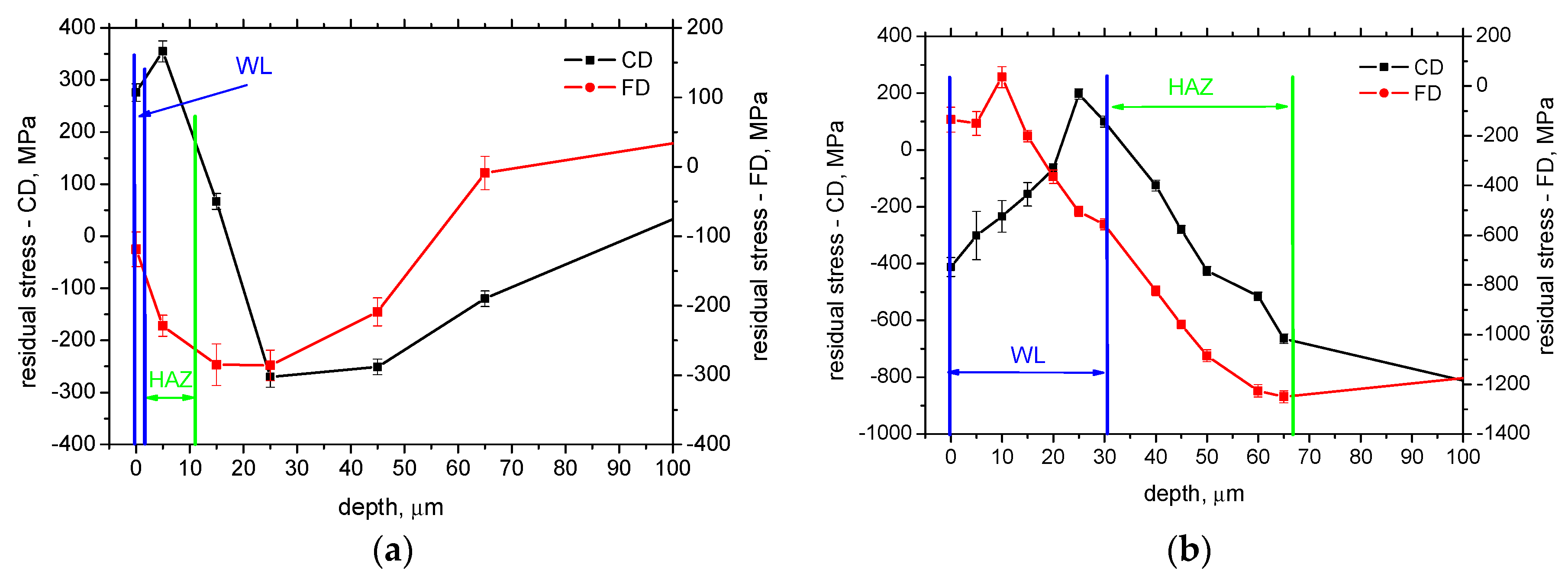
- Measured residual stresses after hard turning are strongly affected by the phase transformation for WL and XRD sensing depth;
- -
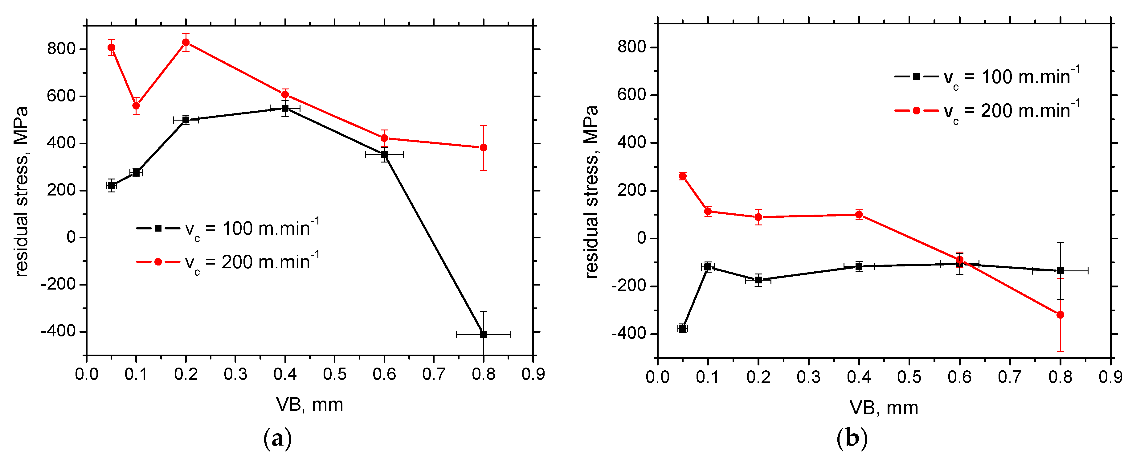
- Residual stresses in FD are mostly compressive as contrasted against CD;
- -
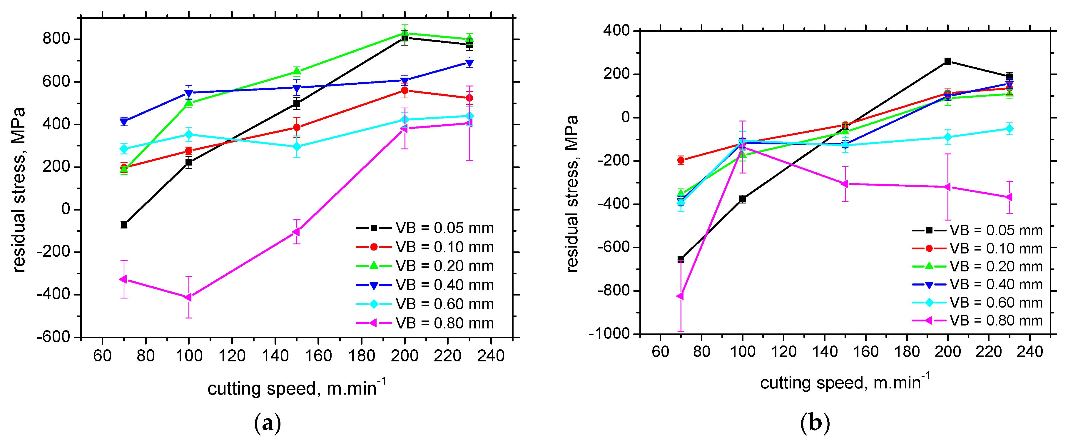
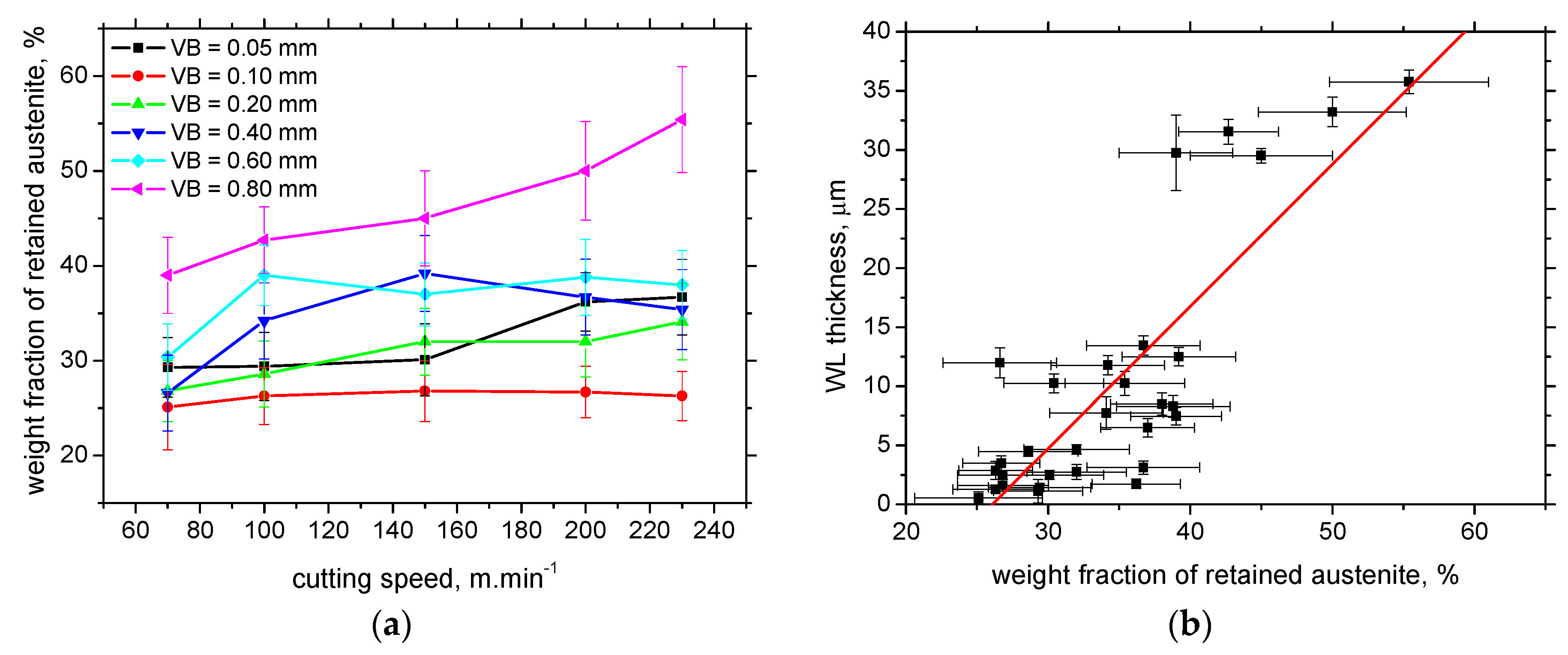
- Cutting speed tends to shift the residual surface stresses towards the tensile region and/or increases the magnitude of tensile stresses;
- -
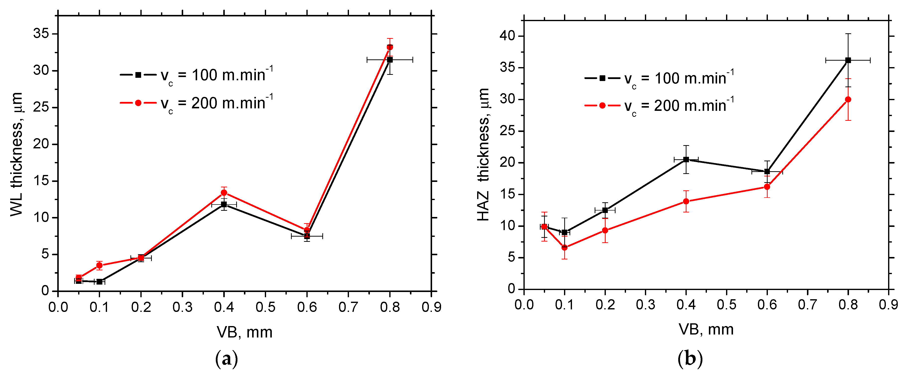
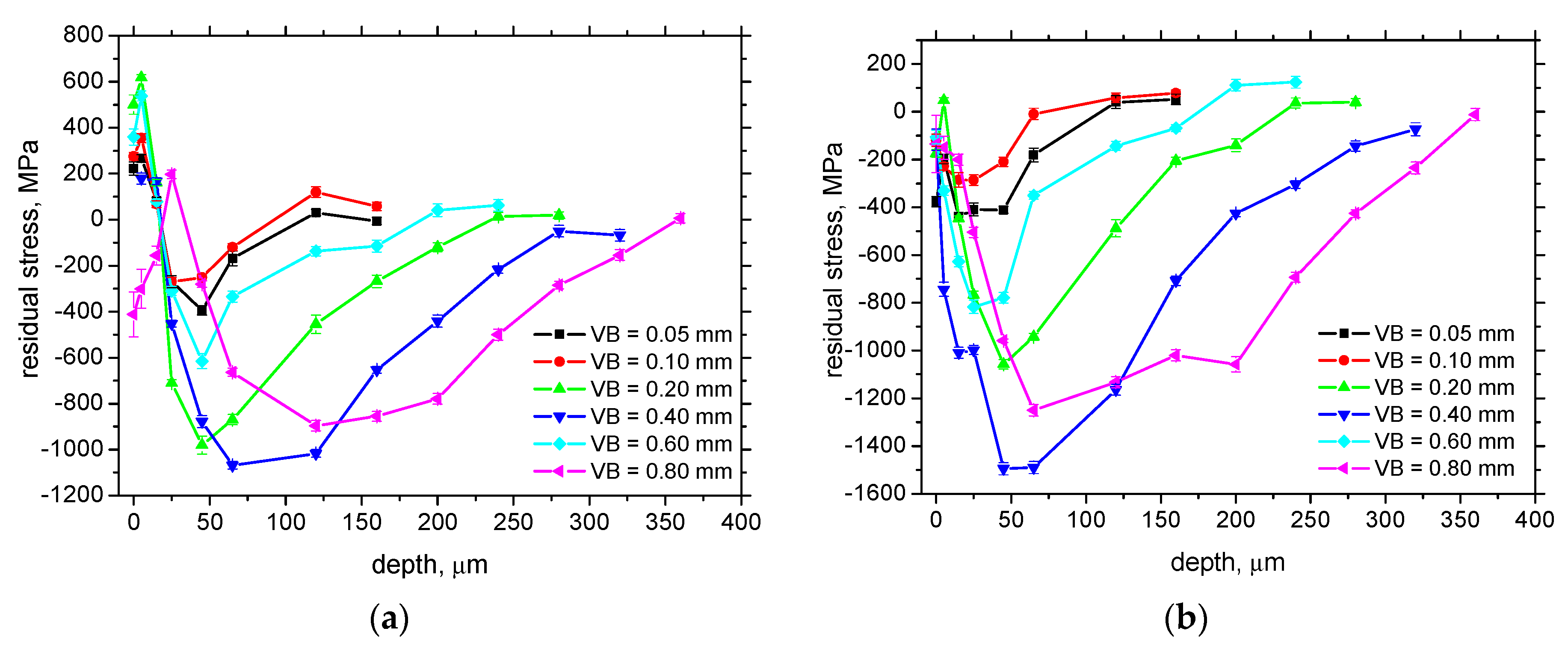
- Higher VB increases the penetration depth of residual stresses.
- -
- Phase transformation tends to shift the residual stresses towards the compressive region;
- -
- The evolution of residual stresses is reversed on the boundary between WL and HAZ;
- -
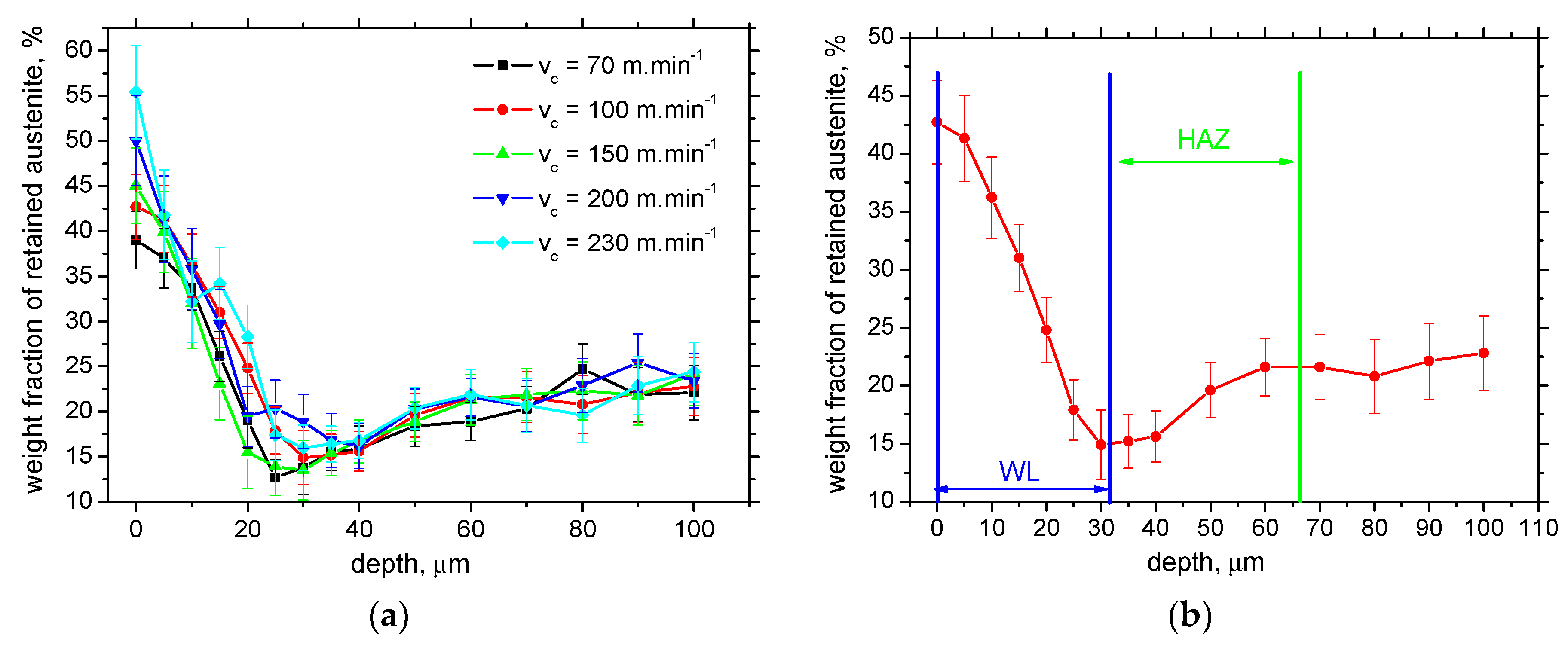
- The austenite fraction increases along with the increasing thickness of WL;
- -
- The austenite fraction in the near-surface WL is increased, whereas it is decreased as compared with the bulk in the HAZ and near the boundary between WL and HAZ;
- -
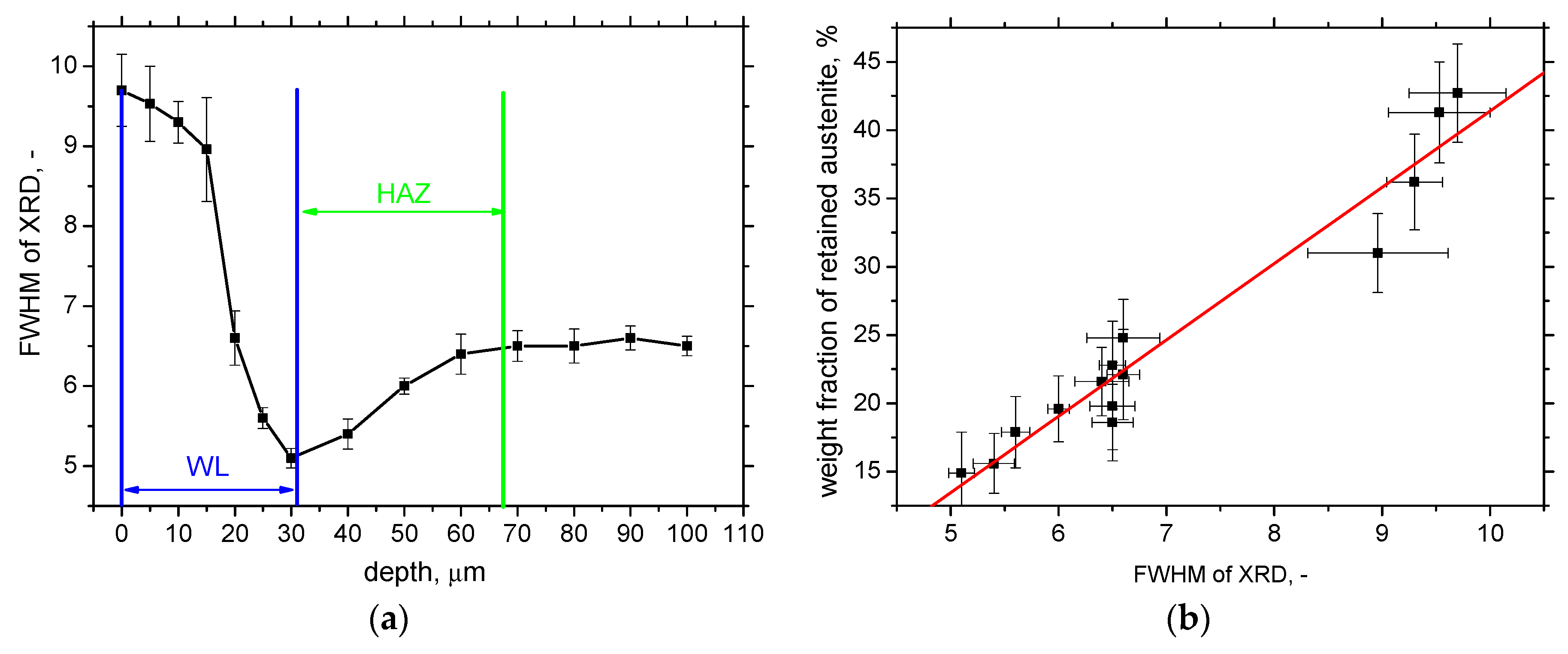
- FWHM of XRD and the corresponding microhardness of WL and HAZ are driven by martensite dislocation density, and the contribution of retained austenite is only minor.
Author Contributions
Funding
Institutional Review Board Statement
Informed Consent Statement
Data Availability Statement
Conflicts of Interest
References
- Tönshoff, H.K.; Arendt, C.; Ben Mor, R. Cutting of hardened steel. CIRP Ann. 2000, 49, 547–564. [Google Scholar] [CrossRef]
- Tönshoff, H.K.; Wobker, H.G.; Brandt, D. Hartbearbeitung aus der sicht der forschung. VDI-Berichte 1993, 988, 189–209. [Google Scholar]
- Breidenstein, B.; Denkena, B.; Krödel, A.; Prasanthan, V.; Poll, G.; Pape, F.; Coors, T. Production-Related Surface and Subsurface Properties and Fatigue Life of Hybrid Roller Bearing Components. Metals 2020, 10, 1339. [Google Scholar] [CrossRef]
- Guo, Y.B.; Sahni, J. A comparative study of hard turned and cylindrical ground white layers. Int. J. Mach. Tool Manuf. 2004, 44, 135–145. [Google Scholar] [CrossRef]
- Tönshoff, H.K. Environmental and Ecological Aspects of Cutting—State, Developments, Potential. In Proceedings of the ICEM Meeting, Ecology and Economy in Metal Forming and Cutting, Eindhoven, The Netherlands, June 1997. [Google Scholar]
- Koenig, W.; Komanduri, R.; Tönshoff, H.K.; Ackerschott, G. Machining of Hard Materials. CIRP Ann. 1984, 3, 417–427. [Google Scholar] [CrossRef]
- Ueda, T.; Al Huda, M.; Yamada, K.; Nakayama, K.; Kudo, H. Temperature Measurement of CBN Tool in Turning of Hardened Steel. CIRP Ann. 1999, 48, 63–66. [Google Scholar] [CrossRef]
- Tekkaya, B.; Meurer, M.; Münstermann, S. Modeling of grain size evolution with different approaches via FEM when hard machining of AISI 4140. Metals 2020, 10, 1296. [Google Scholar] [CrossRef]
- Bandt, D. Randzonenbeeinflussung Beim Hartdrehen. Ph.D. Thesis, Universität Hannover, Hanover, Germany, 1995. [Google Scholar]
- Bedekar, V.; Shivpuri, R.; Chaudhari, R.; Scott Hyde, R. Nanostructural evolution of hard turning layers in response to insert geometry, cutting parameter and material microstructure. CIRP Ann. 2013, 62, 63–66. [Google Scholar] [CrossRef]
- Neslušan, M. Turning of Hardened Steels, 1st ed.; University of Žilina: Žilina, Slovakia, 2010. [Google Scholar]
- Čilliková, M.; Mičietová, A.; Čep, R.; Mičieta, B.; Neslušan, M.; Kejzlar, P. Asymmetrical Barkhausen Noise of a Hard Milled Surface. Materials 2021, 14, 1293. [Google Scholar] [CrossRef]
- Wang, J.Y.; Liu, C.R. The effect of tool flank wear on the heat transfer, thermal damage and cutting mechanics in finishing hard turning. CIRP Ann. 1999, 48, 53–58. [Google Scholar] [CrossRef]
- Agha, S.R.; Liu, C.R. Experimental study on the performance of superfinish hard turned surfaces in rolling contact. Wear 2000, 244, 52–59. [Google Scholar] [CrossRef]
- Hashimoto, F.; Guo, Y.B.; Waren, A.W. Surface integrity difference between hard turned and ground surfaces and its impact of fatigue life. CIRP Ann. 2006, 55, 81–84. [Google Scholar] [CrossRef]
- Zhou, S.B.; Huab, F.; Zhou, W.; Cheng, L.; Hu, C.Y.; Wu, K.M. Effect of retained austenite on impact toughness and fracture behavior of medium carbon submicron-structured bainitic steel. J. Mater. Res. Technol. 2021, 14, 1021–1034. [Google Scholar] [CrossRef]
- Morris, D.; Sadeghi, F.; Singh, K.; Voothaluru, R. Residual stress formation and stability in bearing steels due to fatigue induced retained austenite transformation. Int. J. Fatigue 2020, 136, 105610. [Google Scholar] [CrossRef]
- Cetindag, H.A.; Cicek, A.; Ucak, N. The effects of CryoMQL conditions on tool wear and surface integrity in hard turning of AISI 52100 bearing steel. J. Manuf. Proc. 2020, 56, 463–473. [Google Scholar] [CrossRef]
- Basten, S.; Kirsch, B.; Ankener, W.; Smaga, M.; Beck, T.; Uebel, J.; Seewing, J.; Aurich, J.C. Influence of different cooling strategies during hard turning of AISI 52100—part I: Thermo-mechanical load, tool wear, surface topography and manufacturing accuracy. Proc. CIRP 2020, 87, 77–82. [Google Scholar] [CrossRef]
- Attanasion, A.; Umbrello, D.; Cappellini, C.; Rotella, G.; M’Saoubi, R. Tool wear effects on white and dark layer formation in hard turning of AISI 52100 steel. Wear 2012, 286–287, 98–107. [Google Scholar] [CrossRef]
- Bosheh, S.S.; Mativenga, P.T. White layer formation in hard turning of H13 tool steel at high cutting speeds using CBN tooling. Int. J. Mach. Tools Manuf. 2006, 46, 225–233. [Google Scholar] [CrossRef]
- Alok, A.; Das, M. White layer analysis of hard turned AISI 52100 steel with the fresh tip of newly developed HSN2 coated insert. J. Manuf. Proc. 2019, 46, 16–25. [Google Scholar] [CrossRef]
- Umbrello, D.; Ambrogio, D.; Filice, L.; Shivpuri, R. A hybrid finite element method–artificial neural network approach for predicting residual stresses and the optimal cutting conditions during hard turning of AISI 52100 bearing steel. Mater. Des. 2008, 29, 873–883. [Google Scholar] [CrossRef]
- Hosseini, S.B.; Klement, U. A descriptive phenomenological model for white layer formation in hard turning of AISI 52100 bearing steel. CIRP J. Manuf. Sci. Technol. 2021, 32, 299–310. [Google Scholar] [CrossRef]
- Mittal, S.; Liu, C.R. A method of modeling residual stresses in super finish hard turning. Wear 1998, 218, 21–33. [Google Scholar] [CrossRef]
- Williamson, G.K.; Smallman, R. Dislocation densities in some annealed and cold-worked metals from measurements on the X-ray debye-scherrer spectrum. Philos. Mag. 1955, 1, 34–46. [Google Scholar] [CrossRef]
- Mittemeijer, E.J.; Scardi, P. Diffraction Analysis of the Microstructure of Materials, 1st ed.; Springer: Berlin, Germany, 2004. [Google Scholar]
- Neslušan, M.; Uríček, J.; Mičietová, A.; Minárik, P.; Píška, M.; Čilliková, M. Decomposition of cutting forces with respect to chip segmentation and white layer thickness when hard turning 100Cr6. J. Manuf. Proc. 2020, 50, 475–484. [Google Scholar] [CrossRef]
- Čilliková, M.; Mičietová, A.; Čep, R.; Jacková, M.; Minárik, P.; Neslušan, M.; Kouřil, K. Analysis of Surface State after Turning of High Tempered Bearing Steel. Materials 2022, 15, 1718. [Google Scholar] [CrossRef]
- Smallman, R.E.; Ngan, A.H.W. Modern Physical Metallurgy, 8th ed.; Butterworth-Heinemann: Amsterdam, The Netherlands, 2014. [Google Scholar]


| Cutting insert | DNGA 150408, PCBN, 70% of CBN, TiN coated |
| Inset geometry | rε = 0.8 mm, chamfer (rake) angle −35° of width 250 μm, entering angle 93° |
| Feed f | kept constant at 0.09 mm.rev−1 |
| Cutting depth ap | kept constant at 0.25 mm |
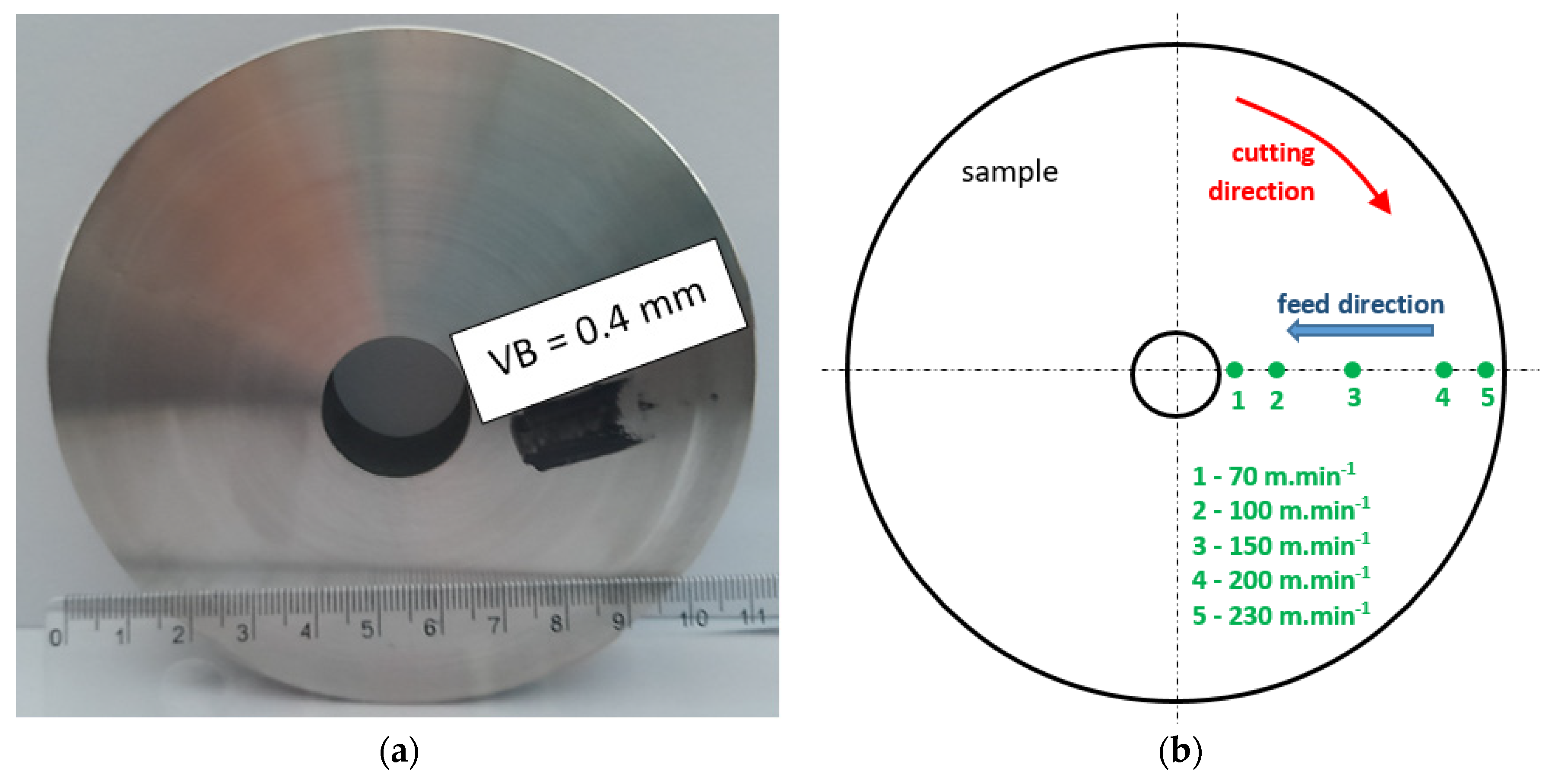
| Cutting speed vc | in the range from 70 to 230 m.min−1; see Figure 1 |
| Average VB, mm | 0.05 | 0.1 | 0.2 | 0.4 | 0.6 | 0.8 |
| VB at the beginning of the test, mm | 0.04 | 0.087 | 0.175 | 0.37 | 0.562 | 0.745 |
| VB at the end of the test, mm | 0.06 | 0.113 | 0.225 | 0.43 | 0.638 | 0.855 |
| vc | VB = 0.05 mm | VB = 0.10 mm | VB = 0.20 mm | VB = 0.40 mm | VB = 0.60 mm | VB = 0.80 mm |
|---|---|---|---|---|---|---|
| 70 m.min−1 | 1.3 ± 1.0 | 0.6 ± 0.5 | 2.5 ± 0.4 | 12 ± 1.2 | 10.3 ± 0.8 | 29.8 ± 3.2 |
| 100 m.min−1 | 1.4 ± 0.3 | 1.3 ± 0.3 | 4.5 ± 0.5 | 11.8 ± 0.8 | 7.5 ± 0.7 | 31.5 ± 2.0 |
| 150 m.min−1 | 2.5 ± 0.4 | 1.6 ± 0.4 | 2.8 ± 0.6 | 12.5 ± 0.8 | 6.5 ± 0.8 | 29.5 ± 0.6 |
| 200 m.min−1 | 1.8 ± 0.4 | 3.5 ± 0.6 | 4.6 ± 0.4 | 13.4 ± 0.8 | 8.3 ± 0.9 | 33.2 ± 1.2 |
| 230 m.min−1 | 3.1 ± 0.5 | 2.9 ± 0.7 | 7.7 ± 1.3 | 10.2 ± 1.0 | 8.5 ± 0.9 | 35.8 ± 1.0 |
| vc | VB = 0.05 mm | VB = 0.10 mm | VB = 0.20 mm | VB = 0.40 mm | VB = 0.60 mm | VB = 0.80 mm |
|---|---|---|---|---|---|---|
| 70 m.min−1 | 8.8 ± 1.7 | 9.8 ± 1.7 | 14.0 ± 1.3 | 21.7 ± 1.7 | 20.2 ± 2.2 | 37.8 ± 2.0 |
| 100 m.min−1 | 9.9 ± 1.7 | 9.0 ± 2.3 | 12.5 ± 1.2 | 20.5 ± 2.2 | 18.6 ± 1.7 | 36.2 ± 4.2 |
| 150 m.min−1 | 10.5 ± 0.6 | 7.0 ± 1.5 | 10.8 ± 1.5 | 17.8 ± 2.7 | 17.5 ± 0.9 | 32.5 ± 3.0 |
| 200 m.min−1 | 9.9 ± 2.3 | 6.6 ± 1.8 | 9.3 ± 1.9 | 13.9 ± 1.7 | 16.2 ± 1.7 | 29.9 ± 3.3 |
| 230 m.min−1 | 8.8 ± 0.8 | 7.5 ± 0.8 | 8.0 ± 1.0 | 8.8 ± 1.1 | 13.5 ± 0.9 | 27.5 ± 2.7 |
| vc | WL | HAZ |
|---|---|---|
| 70 m.min−1 | 995 ± 23 | 638 ± 34 |
| 100 m.min−1 | 953 ± 25 | 641 ± 29 |
| 150 m.min−1 | 930 ± 29 | 662 ± 22 |
| 200 m.min−1 | 920 ± 35 | 670 ± 26 |
| 230 m.min−1 | 848 ± 37 | 683 ± 16 |
| WL | HAZ | Stress CD | Stress FD | Austenite | |
|---|---|---|---|---|---|
| VB | ↑ | ↑ | - | - | ↑ |
| cutting speed | - | - | ↑* | ↑* | - |
Disclaimer/Publisher’s Note: The statements, opinions and data contained in all publications are solely those of the individual author(s) and contributor(s) and not of MDPI and/or the editor(s). MDPI and/or the editor(s) disclaim responsibility for any injury to people or property resulting from any ideas, methods, instructions or products referred to in the content. |
© 2023 by the authors. Licensee MDPI, Basel, Switzerland. This article is an open access article distributed under the terms and conditions of the Creative Commons Attribution (CC BY) license (https://creativecommons.org/licenses/by/4.0/).
Share and Cite
Mičietová, A.; Čilliková, M.; Čep, R.; Neslušan, M.; Ganev, N. Study of Residual Stresses and Austenite Gradients in the Surface after Hard Turning as a Function of Flank Wear and Cutting Speed. Materials 2023, 16, 1709. https://doi.org/10.3390/ma16041709
Mičietová A, Čilliková M, Čep R, Neslušan M, Ganev N. Study of Residual Stresses and Austenite Gradients in the Surface after Hard Turning as a Function of Flank Wear and Cutting Speed. Materials. 2023; 16(4):1709. https://doi.org/10.3390/ma16041709
Chicago/Turabian StyleMičietová, Anna, Mária Čilliková, Róbert Čep, Miroslav Neslušan, and Nikolaj Ganev. 2023. "Study of Residual Stresses and Austenite Gradients in the Surface after Hard Turning as a Function of Flank Wear and Cutting Speed" Materials 16, no. 4: 1709. https://doi.org/10.3390/ma16041709