
Experimental Study of Drilling Damage Outcomes in Hybrid Composites with Waste Micro-Inclusions
 , , ,
, , ,  and
and
Abstract
:1. Introduction
2. Materials and Methods
3. Results and Discussion
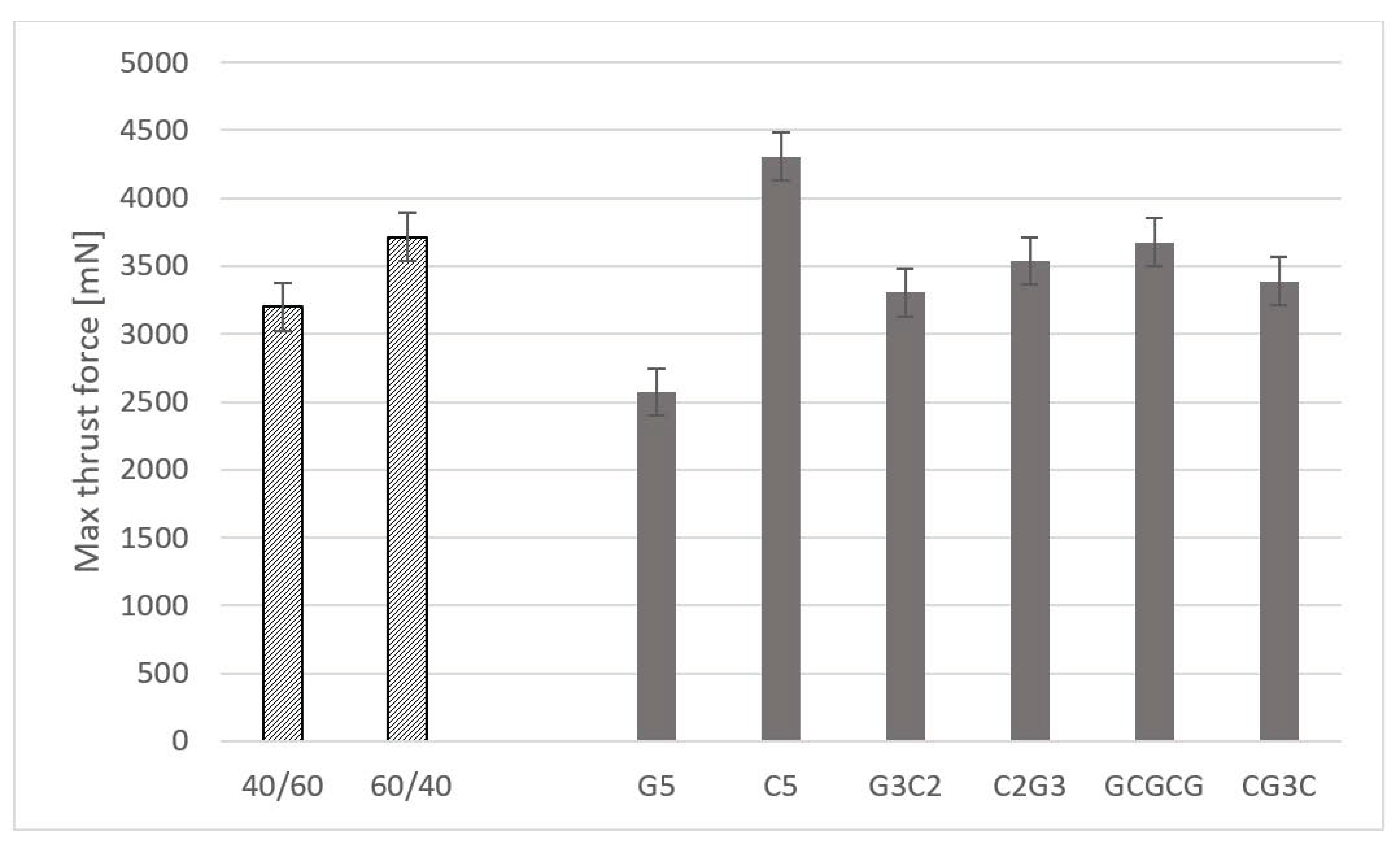
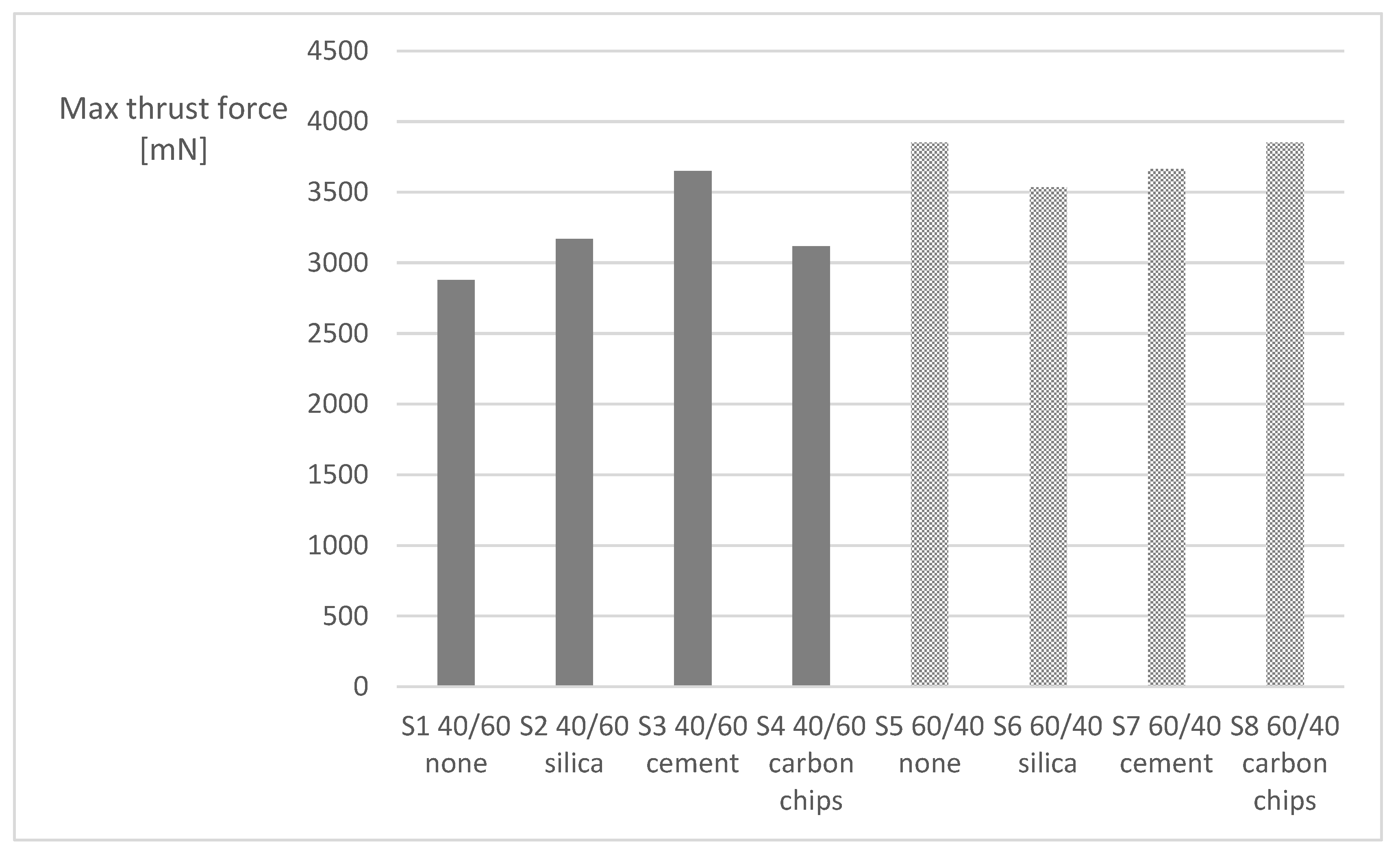
3.1. Thrust Force during Drilling
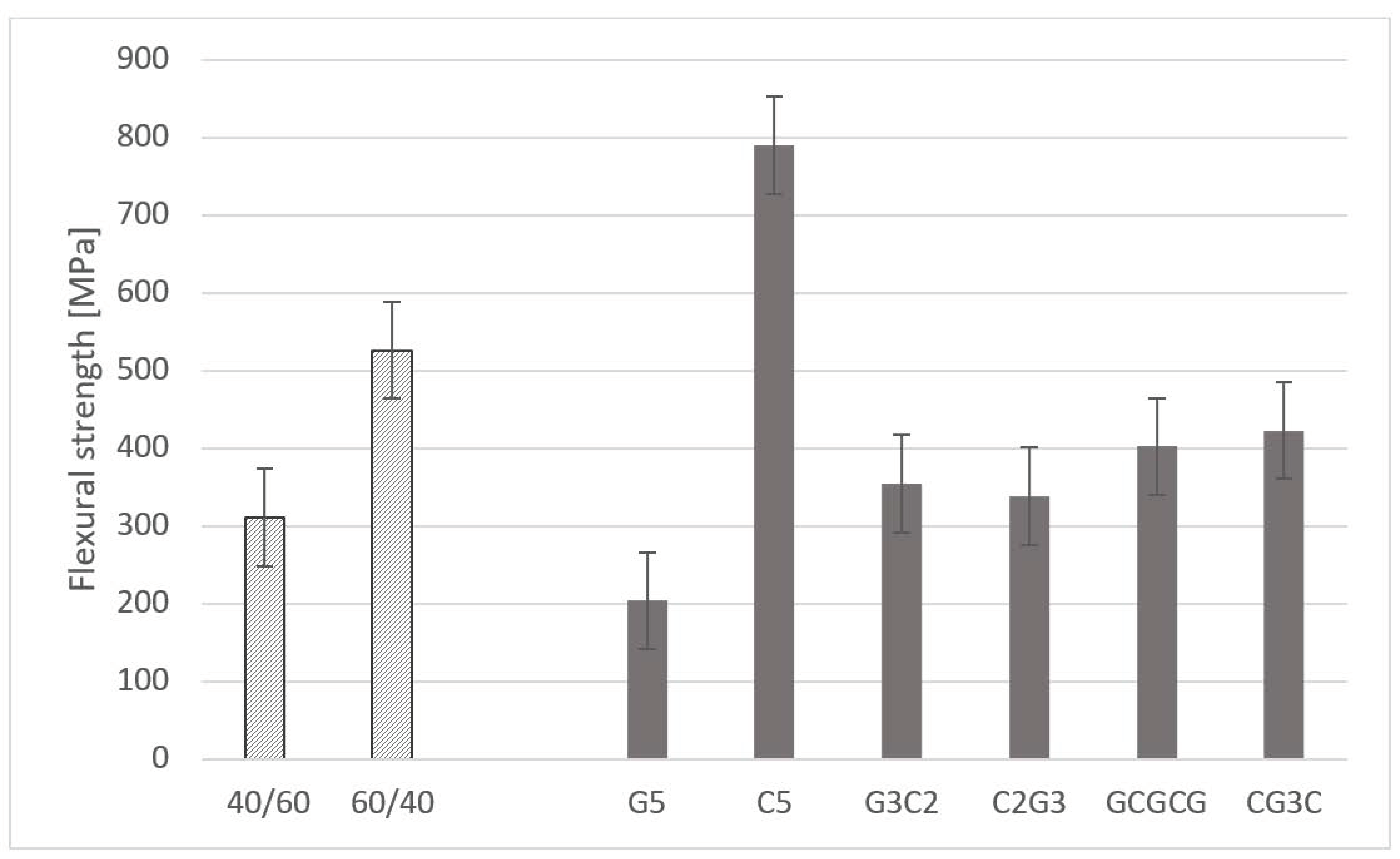
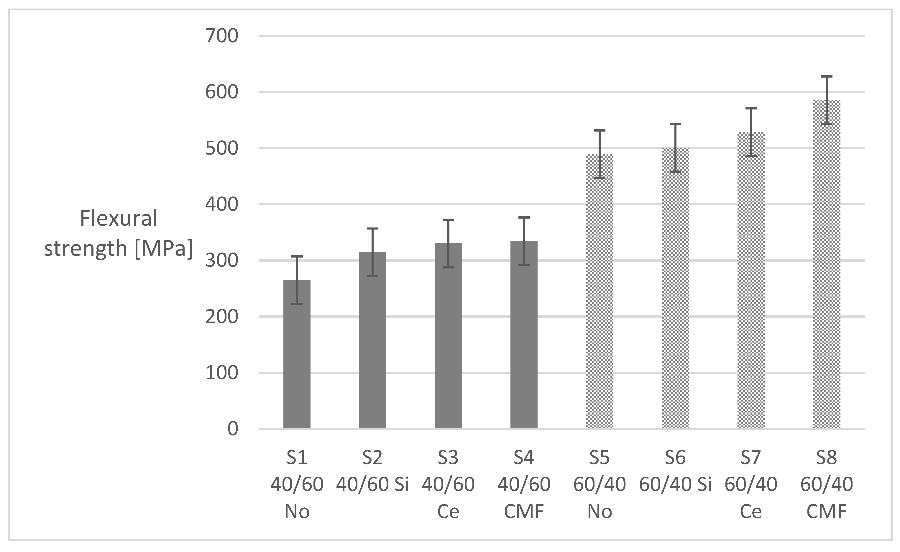
3.2. Flexural Testing
4. Conclusions
Author Contributions
Funding
Data Availability Statement
Acknowledgments
Conflicts of Interest
References
- Schwartz, M.M. Composite Materials Handbook; McGraw Hill: New York, NY, USA, 1992. [Google Scholar]
- Oliveira, P.R.; Ribeiro Filho, S.L.M.; Panzera, T.H.; Christoforo, A.L.; Durão, L.M.D.; Scarpa, F. Hybrid polymer composites made of sugarcane bagasse fibres and disposed rubber particles. Polym. Polym. Compos. 2021, 29, S1280–S1293. [Google Scholar] [CrossRef]
- Ribeiro Filho, S.L.M.; Oliveira, P.R.; Vieira, L.M.G.; Panzera, T.H.; Freire, R.T.S.; Scarpa, F. Hybrid bio-composites reinforced with sisal-glass fibres and Portland cement particles: A statistical approach. Compos. Part B Eng. 2018, 149, 58–66. [Google Scholar] [CrossRef]
- Gemi, L.; Madenci, E.; Ozkılıç, Y.O. Experimental, analytical and numerical investigation of pultruded GFRP composite beams infilled with hybrid FRP reinforced concrete. Eng. Struct. 2021, 244, 112790. [Google Scholar] [CrossRef]
- Dhakal, H.N.; Ismail, S.O. Chapter 7—Future outlooks and challenges of sustainable lightweight composites. In Sustainable Composites for Lightweight Applications; Woodhead Publishing Series in Composites Science and Engineering; Elsevier: Amsterdam, The Netherlands, 2021; pp. 285–290. [Google Scholar]
- Fantuzzi, N.; Bacciocchi, M.; Benedetti, D.; Agnelli, J. The use of sustainable composites for the manufacturing of electric cars. Compos. Part C 2021, 4, 100096. [Google Scholar] [CrossRef]
- Kaewunruen, S.; Liao, P. Sustainability and recyclability of composite materials for railway turnout systems. J. Clean. Prod. 2021, 285, 124890. [Google Scholar] [CrossRef]
- Hocheng, H.; Tsao, C.C. The path towards delamination-free drilling of composite materials. J. Mater. Process. Technol. 2005, 167, 251–264. [Google Scholar] [CrossRef]
- Lopez-Arraiza, A.; Amenabar, I.; Sarrionandia, M.; Aurrekoetxea, J. Experimental Analysis of Drilling Damage in Biocomposite Laminates Manufactured by Resin Transfer Molding. J. Biobased Mater. Bioenergy 2011, 5, 483–490. [Google Scholar] [CrossRef]
- Khashaba, U.A.; El-Sonbaty, I.A.; Selmy, A.I. Machinability analysis in drilling woven GFR/epoxy composites: Part I—Effect of machining parameters. Compos. Part A 2010, 41, 391–400. [Google Scholar] [CrossRef]
- Khashaba, U.A. Mechanics of chip, delamination, and burr formation in drilling supported woven GFRP composites. Alex. Eng. J. 2023, 79, 181–195. [Google Scholar] [CrossRef]
- Chaudhary, V.; Gohil, P.P. Investigations on drilling of bidirectional cotton polyester composite. Mater. Manuf. Process. 2016, 31, 960–968. [Google Scholar] [CrossRef]
- Lotfi, A.; Li, H.; Dao, D.V. Machinability Analysis in Drilling Flax Fiber-Reinforced Polylactic Acid Bio-Composite Laminates. Int. J. Chem. Mater. Biomol. Sci. 2019, 13, 9. [Google Scholar]
- Díaz-Álvarez, A.; Rubio-López, A.; Santiuste, C.; Miguélez, M.H. Experimental analysis of drilling induced damage in biocomposites. Text. Res. J. 2018, 88, 2544–2558. [Google Scholar] [CrossRef]
- Díaz-Álvarez, A.; Díaz-Álvarez, J.; Santiuste, C.; Miguélez, M.H. Experimental and numerical analysis of the influence of drill point angle when drilling biocomposites. Compos. Struct. 2019, 209, 700–709. [Google Scholar] [CrossRef]
- Belaadi, A.; Laouici, H.; Bourchak, M. Mechanical and drilling performance of short jute fiber-reinforced polymer biocomposites: Statistical approach. Int. J. Adv. Manuf. Technol. 2020, 106, 1989–2000. [Google Scholar] [CrossRef]
- Gemi, L.; Koklü, U.; Yazman, S.; Morkavuk, S. The effects of stacking sequence on drilling machinability of filament wound hybrid composite pipes: Part-1 mechanical characterization and drilling tests. Compos. Part B 2020, 186, 107787. [Google Scholar] [CrossRef]
- Gemi, L.; Morkavuk, S.; Köklü, U.; Yazman, S. The effects of stacking sequence on drilling machinability of filament wound hybrid composite pipes: Part-2 damage analysis and surface quality. Compos. Struct. 2020, 235, 111737. [Google Scholar] [CrossRef]
- Ergene, B.; Bolat, C.; Karakilinc, U.; Burak Irez, A. A comprehensive investigation of drilling performance of anisotropic stacked glass-carbon fiber reinforced hybrid laminate composites. Polym. Compos. 2023, 44, 2656–2670. [Google Scholar] [CrossRef]
- Ozsoy, N.; Eksi, S.; Ozsoy, M. Cutting parameters optimization of hybrid fiber composite during drilling. Mater. Test. 2023, 65, 291–302. [Google Scholar] [CrossRef]
- Giasin, K.; Barouni, A.; Dhakal, H.N.; Featherson, C.; Zitoune, R.; Morkavuk, S.; Koklu, U. Microstructural investigation and hole quality evaluation in S2/FM94 glass-fibre composites under dry and cryogenic conditions. J. Reinf. Plast. Compos. 2021, 40, 273–293. [Google Scholar] [CrossRef]
- Abish, J.; Samal, P.; Narenther, M.S.; Kannan, C.; Balan, A.S.S. Assessment of drilling-induced damage in CFRP under chilled air environment. Mater. Manuf. Process. 2018, 33, 1361–1368. [Google Scholar] [CrossRef]
- Sun, Z.; Geng, D.; Meng, F.; Zhou, L.; Jiang, X.; Zhang, D. High performance drilling of T800 CFRP composites by combining ultrasonic vibration and optimized drill structure. Ultrasonics 2023, 134, 107097. [Google Scholar] [CrossRef] [PubMed]
- Hocheng, H.; Dharan, C.K.H. Delamination during Drilling in Composite Laminates. J. Eng. Ind. 1990, 112, 236–239. [Google Scholar] [CrossRef]
- Rajpurohit, A.; Joannès, S.; Singery, V.; Sanial, P.; Laiarinandrasana, L. Hybrid Effect in In-Plane Loading of Carbon/Glass Fibre Based Inter- and Intraply Hybrid Composites. J. Compos. Sci. 2020, 4, 6. [Google Scholar] [CrossRef]
- Xian, G.; Guo, R.; Li, C. Combined effects of sustained bending loading, water immersion and fiber hybrid mode on the mechanical properties of carbon/glass fiber reinforced polymer composite. Compos. Struct. 2022, 281, 115060. [Google Scholar] [CrossRef]
- Lal, H.M.; Uthaman, A.; Li, C.; Xian, G.; Thomas, S. Combined effects of cyclic/sustained bending loading and water immersion on the interface shear strength of carbon/glass fiber reinforced polymer hybrid rods for bridge cable. Constr. Build. Mater. 2022, 314, 125587. [Google Scholar] [CrossRef]
- Ribeiro Filho, S.L.M.; Thomas, C.; Durão, L.M.D.; Christoforo, A.L.; Bowen, C.; Scarpa, F.; Panzera, T.H. Ultrasonic pulse velocity and physical properties of hybrid composites: A statistical approach. Hybrid Adv. 2023, 2, 100024. [Google Scholar] [CrossRef]
- Liu, D.F.; Tang, Y.J.; Cong, W.L. A review of mechanical drilling for composite laminates. Compos. Struct. 2012, 94, 1265–1279. [Google Scholar] [CrossRef]
- Kumar, D.; Singh, K.K. An approach towards damage free machining of CFRP and GFRP composite material: A review. Adv. Compos. Mater. 2015, 24, 49–63. [Google Scholar] [CrossRef]
- Geng, D.; Liu, Y.; Shao, Z.; Lu, Z.; Cai, J.; Li, X.; Jiang, X.; Zhang, D. Delamination formation, evaluation and suppression during drilling of composite laminates: A review. Compos. Struct. 2019, 216, 168–186. [Google Scholar] [CrossRef]
- Silva, P.; Matos, J.E.; Durão, L.M.P. Analysis of damage outcome in the strength of polymer composite materials. J. Compos. Mater. 2019, 53, 547–560. [Google Scholar] [CrossRef]
- Durão, L.M.P.; Tavares, J.M.R.S.; De Albuquerque, V.H.C.; Gonçalves, D.J.S. Damage evaluation of drilled carbon/epoxy laminates based on area assessment methods. Compos. Struct. 2013, 96, 576–583. [Google Scholar] [CrossRef]
- Nagarajan, V.A.; Rajadurai, J.S.; Kumar, T.A. A digital image analysis to evaluate delamination factor for wind turbine composite laminate blade. Compos. Part B 2012, 43, 3153–3159. [Google Scholar] [CrossRef]
- Devesa, L.F.S. Análise e Quantificação do dano em Materiais Compósitos de matriz Polimérica. Master’s Thesis, ISEP, Porto, Portugal, 2020. [Google Scholar]
- ISO 14125:1998; Fibre Reinforced Plastic Composites—Determination of flexural properties. ISO: Geneva, Switzerland, 1998.
- ASTM D790:2017; Standard Test Methods for Flexural Properties of Unreinforced and Reinforced Plastics and Electrical Insulating Materials. ASTM: West Conshohocken, PA, USA, 2017.


| Factors | Experimental Levels | Short Designation |
|---|---|---|
| Stacking sequence | Glass fibres only | G5 |
| Carbon fibres only | C5 | |
| Glass/Glass/Glass/Carbon/Carbon | G3C2 | |
| Carbon/Carbon/Glass/Glass/Glass | C2G3 | |
| Carbon/Glass/Glass/Glass/Carbon | CG3C | |
| Glass/Carbon/Glass/Carbon/Glass | GCGCG | |
| Volume fraction (wt%) | 40/60 | - |
| 60/40 | ||
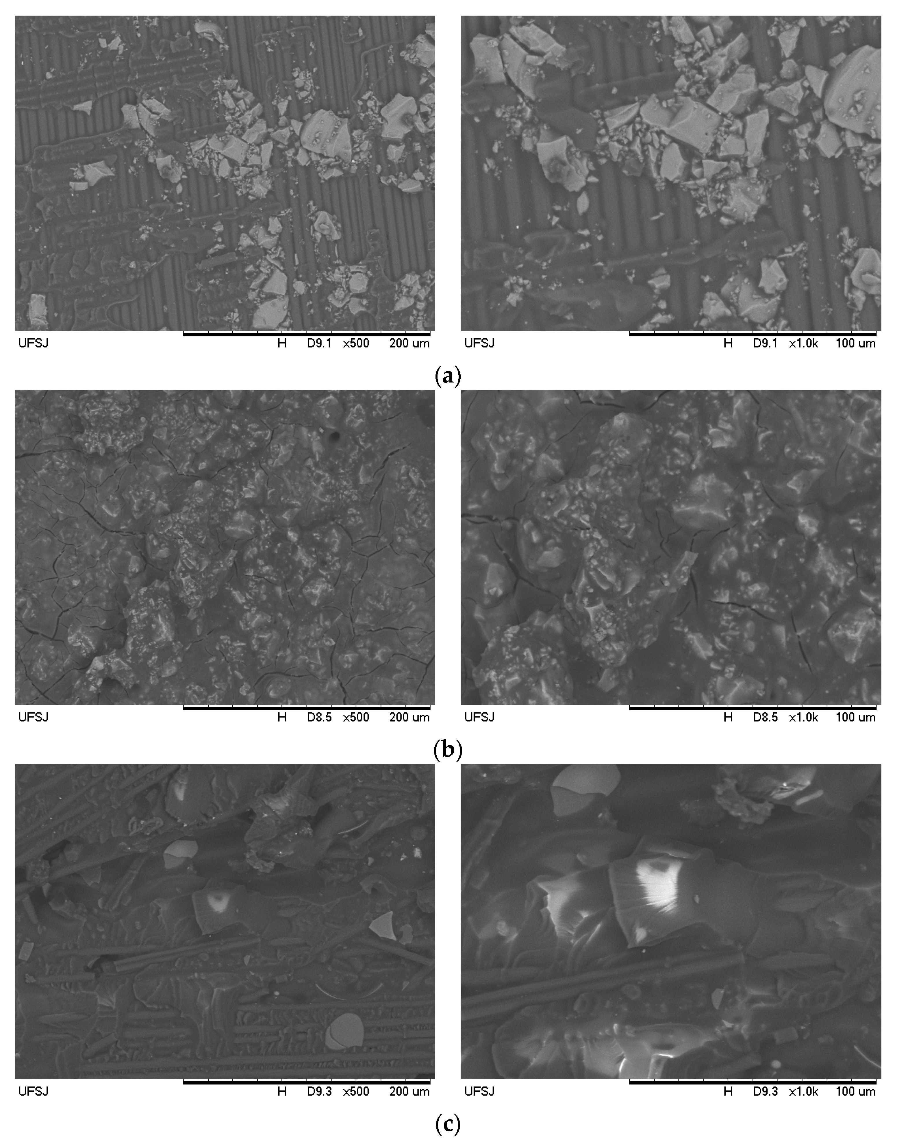
| Particle type | No particle | No |
| Silica, 9% wt, 2.7 g/cm3 | Si | |
| Cement, 9% wt, 2.8 g/cm3 | Ce | |
| Recycled carbon microfibres, 9% wt, 1.7 g/cm3 | CMF |
| Subset | Plate # | %Matr/Reinf (vol) | Particle Type | Stacking Sequence |
|---|---|---|---|---|
| S1 | 1 | 40/60 | No | G5 |
| 2 | 40/60 | No | C5 | |
| 3 | 40/60 | No | G3C2 | |
| 4 | 40/60 | No | C2G3 | |
| 5 | 40/60 | No | GCGCG | |
| 6 | 40/60 | No | CG3C | |
| S2 | 7 | 40/60 | Si | G5 |
| 8 | 40/60 | Si | C5 | |
| 9 | 40/60 | Si | G3C2 | |
| 10 | 40/60 | Si | C2G3 | |
| 11 | 40/60 | Si | GCGCG | |
| 12 | 40/60 | Si | CG3C | |
| S3 | 13 | 40/60 | Ce | G5 |
| 14 | 40/60 | Ce | C5 | |
| 15 | 40/60 | Ce | G3C2 | |
| 16 | 40/60 | Ce | C2G3 | |
| 17 | 40/60 | Ce | GCGCG | |
| 18 | 40/60 | Ce | CG3C | |
| S4 | 19 | 40/60 | CMF | G5 |
| 20 | 40/60 | CMF | C5 | |
| 21 | 40/60 | CMF | G3C2 | |
| 22 | 40/60 | CMF | C2G3 | |
| 23 | 40/60 | CMF | GCGCG | |
| 24 | 40/60 | CMF | CG3C | |
| S5 | 25 | 60/40 | No | G5 |
| 26 | 60/40 | No | C5 | |
| 27 | 60/40 | No | G3C2 | |
| 28 | 60/40 | No | C2G3 | |
| 29 | 60/40 | No | GCGCG | |
| 30 | 60/40 | No | CG3C | |
| S6 | 31 | 60/40 | Si | G5 |
| 32 | 60/40 | Si | C5 | |
| 33 | 60/40 | Si | G3C2 | |
| 34 | 60/40 | Si | C2G3 | |
| 35 | 60/40 | Si | GCGCG | |
| 36 | 60/40 | Si | CG3C | |
| S7 | 37 | 60/40 | Ce | G5 |
| 38 | 60/40 | Ce | C5 | |
| 39 | 60/40 | Ce | G3C2 | |
| 40 | 60/40 | Ce | C2G3 | |
| 41 | 60/40 | Ce | GCGCG | |
| 42 | 60/40 | Ce | CG3C | |
| S8 | 43 | 60/40 | CMF | G5 |
| 44 | 60/40 | CMF | C5 | |
| 45 | 60/40 | CMF | G3C2 | |
| 46 | 60/40 | CMF | C2G3 | |
| 47 | 60/40 | CMF | GCGCG | |
| 48 | 60/40 | CMF | CG3C |
| Subset | Plate # | Max Thrust (mN) | 4P Flex Strgth 1 (MPa) | 3P Flex Strgth 1 (MPa) |
|---|---|---|---|---|
| S1 | 1 | 2700 | 173 | 219 |
| 2 | 3313 | 470 | 333 | |
| 3 | 2307 | 147 | 225 | |
| 4 | 2200 | 228 | 236 | |
| 5 | 3352 | 265 | 310 | |
| 6 | 3408 | 306 | 344 | |
| S2 | 7 | 1973 | 122 | 229 |
| 8 | 3623 | 573 | 391 | |
| 9 | 2861 | 291 | 305 | |
| 10 | 3768 | 236 | 366 | |
| 11 | 3601 | 360 | 352 | |
| 12 | 3185 | 306 | 357 | |
| S3 | 13 | 2536 | 87 | 227 |
| 14 | 4843 | 715 | 317 | |
| 15 | 3846 | 212 | 233 | |
| 16 | 3310 | 289 | 244 | |
| 17 | 3714 | 331 | 302 | |
| 18 | 3644 | 349 | 319 | |
| S4 | 19 | 2110 | 79 | 214 |
| 20 | 3318 | 509 | 328 | |
| 21 | 3220 | 275 | 246 | |
| 22 | 3473 | 345 | 250 | |
| 23 | 3428 | 394 | 366 | |
| 24 | 3157 | 404 | 370 | |
| S5 | 25 | 2644 | 264 | 235 |
| 26 | 4874 | 1031 | 480 | |
| 27 | 4303 | 466 | 478 | |
| 28 | 4021 | 426 | 402 | |
| 29 | 3553 | 396 | 396 | |
| 30 | 3722 | 353 | 235 | |
| S6 | 31 | 2989 | 241 | 295 |
| 32 | 4973 | 1029 | 500 | |
| 33 | 2940 | 418 | 447 | |
| 34 | 3678 | 333 | 273 | |
| 35 | 3634 | 444 | 440 | |
| 36 | 3003 | 539 | 307 | |
| S7 | 37 | 2742 | 331 | 255 |
| 38 | 4752 | 957 | 496 | |
| 39 | 3404 | 491 | 466 | |
| 40 | 3708 | 385 | 395 | |
| 41 | 3819 | 478 | 408 | |
| 42 | 3559 | 530 | 347 | |
| S8 | 43 | 2877 | 332 | 250 |
| 44 | 4756 | 1036 | 504 | |
| 45 | 3563 | 534 | 406 | |
| 46 | 4150 | 467 | 381 | |
| 47 | 4318 | 548 | 396 | |
| 48 | 3440 | 596 | 336 |
Disclaimer/Publisher’s Note: The statements, opinions and data contained in all publications are solely those of the individual author(s) and contributor(s) and not of MDPI and/or the editor(s). MDPI and/or the editor(s) disclaim responsibility for any injury to people or property resulting from any ideas, methods, instructions or products referred to in the content. |
© 2023 by the authors. Licensee MDPI, Basel, Switzerland. This article is an open access article distributed under the terms and conditions of the Creative Commons Attribution (CC BY) license (https://creativecommons.org/licenses/by/4.0/).
Share and Cite
Durão, L.M.P.; Matos, J.E.; Alves, J.; Filho, S.M.R.; Panzera, T.H.; Scarpa, F. Experimental Study of Drilling Damage Outcomes in Hybrid Composites with Waste Micro-Inclusions. Materials 2023, 16, 7325. https://doi.org/10.3390/ma16237325
Durão LMP, Matos JE, Alves J, Filho SMR, Panzera TH, Scarpa F. Experimental Study of Drilling Damage Outcomes in Hybrid Composites with Waste Micro-Inclusions. Materials. 2023; 16(23):7325. https://doi.org/10.3390/ma16237325
Chicago/Turabian StyleDurão, Luis M. P., João E. Matos, João Alves, Sérgio Moni Ribeiro Filho, Túlio H. Panzera, and Fabrizio Scarpa. 2023. "Experimental Study of Drilling Damage Outcomes in Hybrid Composites with Waste Micro-Inclusions" Materials 16, no. 23: 7325. https://doi.org/10.3390/ma16237325