
A Review of Characterization and Modelling Approaches for Sheet Metal Forming of Lightweight Metallic Materials
 , ,
, ,  and
and
Abstract
:1. Introduction
2. History of Numerical Methods in Sheet Metal Forming Simulation
3. Constitutive Modelling of Lightweight Alloys
3.1. Advanced Anisotropic Yield Criterion
3.2. Anisotropic Hardening under Proportional Loadings
3.3. Modelling of the Bauschinger Effect under Non-Proportional Loadings
3.4. Application of Crystal Plasticity for Constitutive Modelling
4. Advanced Experimental Techniques to Identify the Constitutive Parameters
4.1. Proportional Loadings
4.1.1. Uniaxial Tension (UT)
4.1.2. Uniaxial Compression (UC)
4.1.3. Simple Shear (SH)
4.1.4. Hydraulic Bulging (HB)
4.1.5. Biaxial Tensile Testing with Cruciform Specimen (BTC)
4.2. Non-Proportional Loadings
4.2.1. Uniaxial Tension-Uniaxial Compression (TC)
4.2.2. Shear-Reverse Shear (SRS)
4.2.3. Bending-Reverse Bending (BRB)
4.2.4. Non-Reverse Strain Path Changes
4.3. Inverse Engineering
5. Evaluation and Modelling of Forming Limit
5.1. Measurement of Surface Strains in Sheet Metal Forming
5.2. Experimental Determination of Forming Limit Diagram (FLD)
5.3. Determination of FLD via Modelling Techniques
5.3.1. Models Based on Bifurcation Theory
5.3.2. Models Based on Geometrical Imperfection Theory
5.3.3. Models Based on Continuum Damage Mechanics (CDM)
5.3.4. Alternative Models
6. Conclusions and Outlook
6.1. Conclusions and Remarks
- In the past few decades, the numerical methods in SMF simulation have undergone rapid development, including from two-dimensional to three-dimensional, from symmetric to asymmetric, from classical to advanced constitutive models, traditional mesh to meshless, etc.
- Plasticity models under NAFR were widely developed and applied in SMF simulation due to high accuracy, high flexibility, user-friendly parameter identification and convenient consideration of the continuous anisotropic/distortional hardening (yield surface evolution) of lightweight alloys under proportional and non-proportional loadings.
- Advanced CP models can capture the underlying process-microstructure-properties for the physical mechanisms. Besides, applying CP models in predicting the constitutive behaviors of lightweight alloys under complex loading conditions (challenging to achieve in mechanical characterization) has drawn significant attention.
- The application of the DIC technique improved the accuracy of mechanical characterization and promoted the development of advanced characterization techniques, e.g., inverse engineering. Novel mechanical characterization methods under SPCs, rather than reverse loadings, are required for the engineering application of advanced lightweight alloys.
- The formability (FLD) of sheet metals is usually assessed experimentally by Nakajima test (out-of-plane) or Marciniak test (in-plane). Several methods were developed to determine the onset of localized necking, e.g., spatial methods, temporal methods and spatio-temporal methods.
- Theoretical models based upon bifurcation theory, geometrical imperfection theory and continuum damage mechanics were developed to predict the forming limit strains of lightweight alloys under various loading conditions, e.g., strain path changes, through coupling different hardening laws and yield criteria.
- Multiscale forming limit diagram (FLD) prediction schemes were developed by combining the CPFEM with the geometrical imperfection theory, e.g., M–K model. Besides, approaches or frameworks by coupling machine learning and CP simulations were proposed to predict the FLD of lightweight alloys.
6.2. Outlook and Future Directions
- ➣
- The development and application of advanced multiscale modelling approaches for the simulations of SMF under particular conditions (or extreme manufacturing), such as hydrogen environments, cryogenic temperatures and heterostructures/laminated materials, is notable.
- ➣
- For phenomenological constitutive modelling, these efforts include the development of the NAFR framework via analytical parameter identification. Attention should be further focused on stress state-dependent anisotropy and hardening due to the specific underlying mechanisms, such as phase transformation and slip/twinning activity in advanced lightweight materials.
- ➣
- The inverse engineering method, as the next-generation of mechanical characterization, for identification of the parameters of advanced constitutive models under large plastic strains should be highlighted. The focus should be on a reasonable choice of the optimization algorithm and the constitutive model. A suitable plasticity model with high flexibility and fidelity should be selected appropriately in inverse engineering.
- ➣
- Machine learning-based methods, such as artificial neural network, are drawing more attention. As fundamental inputs to train and test these data-driven models, massive, accurate and representative data are crucial to the parameterized artificial intelligence framework. This requirement dramatically fosters the development of advanced characterization techniques, including mechanical experiments and virtual data generation based on accurate multi-physics models (e.g., CP) for advanced lightweight materials.
Author Contributions
Funding
Institutional Review Board Statement
Informed Consent Statement
Data Availability Statement
Acknowledgments
Conflicts of Interest
References
- Tisza, M.; Czinege, I. Comparative study of the application of steels and aluminium in lightweight production of automotive parts. Int. J. Lightweight Mater. Manuf. 2018, 1, 229–238. [Google Scholar] [CrossRef]
- Blanco, D.; Rubio, E.M.; Lorente-Pedreille, R.M.; Sáenz-Nuño, M.A. Lightweight Structural Materials in Open Access: Latest Trends. Materials 2021, 14, 6577. [Google Scholar] [CrossRef]
- Gloria, A.; Montanari, R.; Richetta, M.; Varone, A. Alloys for Aeronautic Applications: State of the Art and Perspectives. Metals 2019, 9, 662. [Google Scholar] [CrossRef] [Green Version]
- Mallick, P.K. Materials, Design and Manufacturing for Lightweight Vehicles; Woodhead Publishing: Cambridge, UK, 2020. [Google Scholar]
- Hirsch, J. Recent development in aluminium for automotive application. Trans. Nonferrous Met. Soc. China. 2014, 24, 1995–2002. [Google Scholar] [CrossRef]
- Zeng, X.; Li, M.; Abd El-Hady, D.; Alshitari, W.; Al-Bogami, A.S.; Lu, J.; Amine, K. Commercialization of lithium battery technologies for electric vehicles. Adv. Energy Mater. 2019, 9, 1900161. [Google Scholar] [CrossRef]
- İnci, M.; Büyük, M.; Demir, M.H.; İlbey, G. A review and research on fuel cell electric vehicles: Topologies, power electronic converters, energy management methods, technical challenges, marketing and future aspects. Renew. Sustain. Energy Rev. 2021, 137, 110648. [Google Scholar] [CrossRef]
- Kulekci, M.K. Magnesium and its alloys applications in automotive industry. Int. J. Adv. Manufac-Turing Technol. 2008, 39, 851–865. [Google Scholar] [CrossRef]
- Zhang, W.; Xu, J. Advanced lightweight materials for Automobiles: A review. Mater. Des. 2022, 221, 110994. [Google Scholar] [CrossRef]
- Abd El-Aty, A.; Xu, Y.; Guo, X.; Zhang, S.-H.; Ma, Y.; Chen, D. Strengthening mechanisms, deformation behavior, and anisotropic mechanical properties of Al-Li alloys: A review. J. Adv. Res. 2018, 10, 49–67. [Google Scholar] [CrossRef]
- Assempour, A.; Emami, M.R. Pressure estimation in the hydroforming process of sheet metal pairs with the method of upper bound analysis. J. Mater. Process. Technol. 2009, 209, 2270–2276. [Google Scholar] [CrossRef]
- Lan, J.; Dong, X.; Li, Z. Inverse finite element approach and its application in sheet metal forming. J. Mater. Process. Technol. 2005, 170, 624–631. [Google Scholar] [CrossRef]
- Kim, S.H.; Kim, S.H.; Huh, H. Finite element inverse analysis for the design of intermediate dies in multi-stage deep-drawing processes with large aspect ratio. J. Mater. Process. Technol. 2001, 113, 779–785. [Google Scholar] [CrossRef]
- Tang, B.; Li, Y.; Lu, X. Developments of multistep inverse finite element method and its application in formability prediction of multistage sheet metal forming. J. Manuf. Sci. Eng. 2010, 132, 041013. [Google Scholar] [CrossRef]
- Van Houtte, P.; Gawad, J.; Eyckens, P.; Van Bael, B.; Samaey, G.; Roose, D. Multi-scale modelling of the development of heterogeneous distributions of stress, strain, deformation texture and anisotropy in sheet metal forming. Procedia IUTAM 2012, 3, 67–75. [Google Scholar] [CrossRef]
- Barik, S.; Narayanan, R.; Sahoo, N. Forming response of AA5052–H32 sheet deformed using a shock tube. Trans. Nonferrous Met. Soc. China 2020, 30, 603–618. [Google Scholar] [CrossRef]
- Nakata, T.; Xu, C.; Ohashi, H.; Yoshida, Y.; Yoshida, K.; Kamado, S. New Mg–Al based alloy sheet with good room-temperature stretch formability and tensile properties. Scr. Mater. 2020, 180, 16–22. [Google Scholar] [CrossRef]
- Badrish, A.; Morchhale, A.; Kotkunde, N.; Singh, S.K. Influence of material modeling on warm forming behavior of nickel based super alloy. Int. J. Mater. Form. 2020, 13, 445–465. [Google Scholar] [CrossRef]
- Neto, D.; Oliveira, M.; Santos, A.; Alves, J.; Menezes, L. Influence of boundary conditions on the prediction of springback and wrinkling in sheet metal forming. Int. J. Mech. Sci. 2017, 122, 244–254. [Google Scholar] [CrossRef] [Green Version]
- Fei, H.; Mo, J.; Qi, H.; Long, R.; Cui, X.; Li, Z. Springback prediction for incremental sheet forming based on FEM-PSONN technology. Trans. Nonferrous Met. Soc. China 2013, 23, 1061–1071. [Google Scholar] [CrossRef]
- Min, J.; Guo, N.; Hou, Y.; Jiang, K.; Chen, X.; Carsley, J.E.; Lin, J. Effect of tension-compression testing strategy on kinematic model calibration and springback simulation of advanced high strength steels. Int. J. Mater. Form. 2021, 14, 435–448. [Google Scholar] [CrossRef]
- Hou, Y.; Min, J.; Lin, J.; Liu, Z.; Carsley, J.E.; Stoughton, T.B. Springback prediction of sheet metals using improved material models. Procedia Eng. 2017, 207, 173–178. [Google Scholar] [CrossRef]
- Hu, Q.; Zhang, F.; Li, X.; Chen, J. Overview on the prediction models for sheet metal forming failure: Necking and ductile fracture. Acta Mech. Solida Sin. 2018, 31, 259–289. [Google Scholar] [CrossRef]
- Jeong, W.; Kim, C.; Lee, C.-A.; Bong, H.J.; Hong, S.-H.; Lee, M.-G. A probabilistic mean-field and microstructure based finite element modeling for predicting mechanical and ductile fracture behavior of the cast aluminum alloy. Int. J. Plast. 2022, 154, 103299. [Google Scholar] [CrossRef]
- Li, T.; Garg, R.; Galvin, J.; Pannala, S. Open-source MFIX-DEM software for gas-solids flows: Part II—Validation studies. Powder Technol. 2012, 220, 138–150. [Google Scholar] [CrossRef]
- Neuwirth, J.; Antonyuk, S.; Heinrich, S.; Jacob, M. CFD–DEM study and direct measurement of the granular flow in a rotor granulator. Chem. Eng. Sci. 2013, 86, 151–163. [Google Scholar] [CrossRef]
- Martínez-Valle, Á.; Martínez-Jiménez, J.M.; Goes, P.; Faes, K.; De Waele, W. Multiphysics fully-coupled modelling of the electromagnetic compression of steel tubes. In Advanced Materials Research; Trans Tech Publications Ltd.: Zurich, Switzerland, 2011; pp. 31–39. [Google Scholar]
- Liu, X.; Li, H.; Zhan, M. A review on the modeling and simulations of solid-state diffusional phase transformations in metals and alloys. Manuf. Rev. 2018, 5, 10. [Google Scholar] [CrossRef] [Green Version]
- Rodríguez-Martínez, J.A.; Rusinek, A.; Pesci, R.; Zaera, R. Experimental and numerical analysis of the martensitic transformation in AISI 304 steel sheets subjected to perforation by conical and hemispherical projectiles. Int. J. Solids Struct. 2013, 50, 339–351. [Google Scholar] [CrossRef] [Green Version]
- Jo, S.Y.; Hong, S.; Han, H.-N.; Lee, M.-G. Modeling and Simulation of Steel Rolling with Microstructure Evolution: An Overview. Steel Res. Int. 2023, 2200260. [Google Scholar] [CrossRef]
- Park, J.; Rout, M.; Min, K.-M.; Chen, S.-F.; Lee, M.-G. A fully coupled crystal plasticity-cellular automata model for predicting thermomechanical response with dynamic recrystallization in AISI 304LN stainless steel. Mech. Mater. 2022, 167, 104248. [Google Scholar] [CrossRef]
- Liewald, M.; Riedmüller, K.R. A new one-phase material model for the numerical prediction of critical material flow conditions in thixoforging processes. CIRP Ann. 2019, 68, 293–296. [Google Scholar] [CrossRef]
- Amaral, R.; Santos, A.D.; de Sá José, C.; Miranda, S. Formability prediction for AHSS materials using damage models. In Journal of Physics: Conference Series; IOP Publishing: Bristol, England, 2017; p. 012018. [Google Scholar]
- Oliveira, M.C.; Fernandes, J.V. Modelling and simulation of sheet metal forming processes. Metals 2019, 9, 1356. [Google Scholar] [CrossRef] [Green Version]
- Wadas, T.; Tisza, M. Lightweight Manufacturing of Automotive Parts; IOP Publishing: Bristol, England, 2020. [Google Scholar]
- Gronostajski, Z.; Pater, Z.; Madej, L.; Gontarz, A.; Lisiecki, L.; Łukaszek-Sołek, A.; Łuksza, J.; Mróz, S.; Muskalski, Z.; Muzykiewicz, W. Recent development trends in metal forming. Arch. Civ. Mech. Eng. 2019, 19, 898–941. [Google Scholar] [CrossRef]
- Wang, P.-Y.; Wang, Z.-J.; Xiang, N.; Li, Z.-X. Investigation on changing loading path in sheet metal forming by applying a property-adjustable flexible-die. J. Manuf. Processes 2020, 53, 364–375. [Google Scholar] [CrossRef]
- Flegler, F.; Neuhäuser, S.; Groche, P. Influence of sheet metal texture on the adhesive wear and friction behaviour of EN AW-5083 aluminum under dry and starved lubrication. Tribol. Int. 2020, 141, 105956. [Google Scholar] [CrossRef]
- Evin, E.; Tomáš, M. Verification of Friction Models Implemented in the Simulation Software. In Materials Science Forum; Trans Tech Publications Ltd.: Zurich, Switzerland, 2020; pp. 223–231. [Google Scholar]
- Shisode, M.P.; Hazrati, J.; Mishra, T.; de Rooij, M.; van den Boogaard, T. Modeling mixed lubrication friction for sheet metal forming applications. Procedia Manuf. 2020, 47, 586–590. [Google Scholar] [CrossRef]
- Sigvant, M.; Pilthammar, J.; Hol, J.; Wiebenga, J.H.; Chezan, T.; Carleer, B.; van den Boogaard, T. Friction in sheet metal forming: Influence of surface roughness and strain rate on sheet metal forming simulation results. Procedia Manuf. 2019, 29, 512–519. [Google Scholar] [CrossRef]
- Sulaiman, M.; Farahana, R.; Bienk, K.; Nielsen, C.; Bay, N. Effects of DLC/TiAlN-coated die on friction and wear in sheet-metal forming under dry and oil-lubricated conditions: Experimental and numerical studies. Wear 2019, 438, 203040. [Google Scholar] [CrossRef]
- Seshacharyulu, K.; Bandhavi, C.; Naik, B.B.; Rao, S.S.; Singh, S. Understanding Friction in sheet metal forming—A review. Mater. Today Proc. 2018, 5, 18238–18244. [Google Scholar] [CrossRef]
- Park, J.; Min, K.M.; Kim, H.; Hong, S.-H.; Lee, M.-G. Integrated Computational Materials Engineering for Advanced Automotive Technology: With Focus on Life Cycle of Automotive Body Structure. Adv. Mater. Technol. 2022, 2201057. [Google Scholar] [CrossRef]
- El-Aty, A.A.; Guo, X.; Lee, M.-G.; Tao, J.; Hou, Y.; Hu, S.; Li, T.; Wu, C.; Yang, Q. A review on flexibility of free bending forming technology for manufacturing thin-walled complex-shaped metallic tubes. Int. J. Lightweight Mater. Manuf. 2023, 6, 165–188. [Google Scholar] [CrossRef]
- da Silva, G.S.; Kosteski, L.E.; Iturrioz, I. Analysis of the failure process by using the Lattice Discrete Element Method in the Abaqus environment. Theor. Appl. Fract. Mech. 2020, 107, 102563. [Google Scholar] [CrossRef]
- Tallinen, T.; Åström, J.A.; Timonen, J. Discrete element simulations of crumpling of thin sheets. Comput. Phys. Commun. 2009, 180, 512–516. [Google Scholar] [CrossRef]
- Topčagić, Z.; Križaj, D.; Bulić, E. Application of a current sheet in BEM analysis for numerical calculation of torque in the magnetostatic field. IEEE Trans. Magn. 2020, 56, 1–9. [Google Scholar] [CrossRef]
- Saad, M.; Akhtar, S.; Srivastava, M.; Chaurasia, J. Role of simulation in metal forming processes. Mater. Today Proc. 2018, 5, 19576–19585. [Google Scholar] [CrossRef]
- Wu, Y.; Shen, Y.; Chen, K.; Yu, Y.; He, G.; Wu, P. Multi-scale crystal plasticity finite element method (CPFEM) simulations for shear band development in aluminum alloys. J. Alloys Compd. 2017, 711, 495–505. [Google Scholar] [CrossRef]
- Mellbin, Y.; Hallberg, H.; Ristinmaa, M. A combined crystal plasticity and graph-based vertex model of dynamic recrystallization at large deformations. Modell. Simul. Mater. Sci. Eng. 2015, 23, 045011. [Google Scholar] [CrossRef] [Green Version]
- Abd El-Aty, A.; Xu, Y.; Ha, S.; Zhang, S.-H. Computational homogenization of tensile deformation behaviors of a third generation Al-Li alloy 2060-T8 using crystal plasticity finite element method. Mater. Sci. Eng. A 2018, 731, 583–594. [Google Scholar] [CrossRef]
- Abd El-Aty, A.; Zhang, S.-H.; Xu, Y.; Ha, S. Deformation behavior and anisotropic response of 2060 Al-Cu-Li alloy: Experimental investigation and computational homogenization-based crystal plasticity modeling. J. Mater. Res. Technol. 2019, 8, 1235–1249. [Google Scholar] [CrossRef]
- Xue, F.; Li, F.; Li, J.; He, M.; Yuan, Z.; Wang, R. Numerical modeling crack propagation of sheet metal forming based on stress state parameters using XFEM method. Comput. Mater. Sci. 2013, 69, 311–326. [Google Scholar] [CrossRef]
- Yuan, B.; Wang, Z. A multi-deformable bodies solution method coupling finite element with meshless method in sheet metal flexible-die forming. Procedia Eng. 2017, 207, 1641–1646. [Google Scholar] [CrossRef]
- Kochmann, J.; Wulfinghoff, S.; Reese, S.; Mianroodi, J.R.; Svendsen, B. Two-scale FE–FFT-and phase-field-based computational modeling of bulk microstructural evolution and macroscopic material behavior. Comput. Methods Appl. Mech. Eng. 2016, 305, 89–110. [Google Scholar] [CrossRef]
- Gasiorek, D.; Baranowski, P.; Malachowski, J.; Mazurkiewicz, L.; Wiercigroch, M. Modelling of guillotine cutting of multi-layered aluminum sheets. J. Manuf. Process. 2018, 34, 374–388. [Google Scholar] [CrossRef]
- Crutzen, Y.; Boman, R.; Papeleux, L.; Ponthot, J.-P. Lagrangian and arbitrary Lagrangian Eulerian simulations of complex roll-forming processes. C.R. Mec. 2016, 344, 251–266. [Google Scholar] [CrossRef]
- Kaftanoglu, B.; Tekkaya, A. Complete numerical solution of the axisymmetrical deep-drawing problem. J. Eng. Mater. Technol. 1981, 103, 326–332. [Google Scholar] [CrossRef]
- Makinouchi, A. Sheet metal forming simulation in industry. J. Mater. Process. Technol. 1996, 60, 19–26. [Google Scholar] [CrossRef]
- Makinouchi, A.; Teodosiu, C.; Nakagawa, T. Advance in FEM simulation and its related technologies in sheet metal forming. CIRP Ann. 1998, 47, 641–649. [Google Scholar] [CrossRef]
- Tekkaya, A.E. State-of-the-art of simulation of sheet metal forming. J. Mater. Process. Technol. 2000, 103, 14–22. [Google Scholar] [CrossRef]
- Tisza, M. Numerical modelling and simulation in sheet metal forming. J. Mater. Process. Technol. 2004, 151, 58–62. [Google Scholar] [CrossRef] [Green Version]
- Wenner, M.L. Overview—Simulation of Sheet Metal Forming. AIP Conference Proceedings; American Institute of Physics: College Park, MD, USA, 2005; pp. 3–7. [Google Scholar]
- Ahmed, M.; Sekhon, G.; Singh, D. Finite element simulation of sheet metal forming processes. Def. Sci. J. 2005, 55, 389. [Google Scholar] [CrossRef] [Green Version]
- Banabic, D. Sheet Metal Forming Processes: Constitutive Modelling and Numerical Simulation; Springer Science & Business Media: Berlin, Germany, 2010. [Google Scholar] [CrossRef]
- Akhavan Farid, A.; Shen, F.S.; Rahimian Koloor, S.S.; Petrů, M. Quality evaluation of aluminum-AA6061 truncated cone deformed by single point incremental forming. J. Braz. Soc. Mech. Sci. Eng. 2022, 44, 420. [Google Scholar] [CrossRef]
- Yan, B.Y.; Meng, B. Wall thickness control in multi-stage hydroforming of multiwave seal ring with small diameter. IOP Conf. Ser. Mater. Sci. Eng. 2022, 1270, 012067. [Google Scholar] [CrossRef]
- Liu, Y.; Min, J.; Zhang, J.; Cai, W.; Carlson, B.E.; Bobel, A.C.; Hector, L.G.; Sachdev, A.K. Laser-assisted robotic roller forming of an ultrahigh strength martensitic steel. J. Manuf. Process. 2022, 82, 192–202. [Google Scholar] [CrossRef]
- Ablat, M.A.; Qattawi, A. Numerical simulation of sheet metal forming: A review. Int. J. Adv. Manuf. Technol. 2017, 89, 1235–1250. [Google Scholar] [CrossRef]
- Chung, K.; Lee, M.-G. Basics of Continuum Plasticity; Springer: Berlin, Germany, 2018. [Google Scholar] [CrossRef]
- Trzepieciński, T. Recent developments and trends in sheet metal forming. Metals 2020, 10, 779. [Google Scholar] [CrossRef]
- Raabe, D.; Klose, P.; Engl, B.; Imlau, K.-P.; Friedel, F.; Roters, F. Concepts for Integrating Plastic Anisotropy into Metal Forming Simulations. Adv. Eng. Mater. 2002, 4, 169–180. [Google Scholar] [CrossRef]
- Yanagimoto, J.; Oya, T.; Kawanishi, S.; Tiesler, N.; Koseki, T. Enhancement of bending formability of brittle sheet metal in multilayer metallic sheets. CIRP Ann. 2010, 59, 287–290. [Google Scholar] [CrossRef]
- Rydz, D.; Stradomski, G.; Szarek, A.; Kubik, K.; Kordas, P. The Analysis of Pressed Cups Producing Possibilities from Rolled Bimetallic Al-1050 + Cu-M1E Sheets. Materials 2020, 13, 2413. [Google Scholar] [CrossRef]
- Kim, D.; Kim, H.; Kim, J.H.; Lee, M.G.; Kim, K.J.; Barlat, F.; Lee, Y.; Chung, K. Modeling of forming limit for multilayer sheets based on strain-rate potentials. Int. J. Plast. 2015, 75, 63–99. [Google Scholar] [CrossRef]
- Bagheri, A.; Shabani, A.; Toroghinejad, M.R.; Taherizadeh, A. Post-rolling annealing of a multilayered Brass/IFS/Brass composite: An evaluation of anisotropy, formability, and mechanical properties. J. Mater. Res. Technol. 2022, 19, 732–746. [Google Scholar] [CrossRef]
- Page, M.J.; McKenzie, J.E.; Bossuyt, P.M. The PRISMA 2020 statement: An updated guideline for reporting systematic reviews. Syst Rev. 2021, 10, 89. [Google Scholar] [CrossRef]
- Woo, D. On the complete solution of the deep-drawing problem. Int. J. Mech. Sci. 1968, 10, 83–94. [Google Scholar] [CrossRef]
- Tseng, A.A. A generalized finite difference scheme for convection-dominated metal-forming problems. Int. J. Numer. Methods Eng. 1984, 20, 1885–1900. [Google Scholar] [CrossRef]
- Wifi, A.S. An incremental complete solution of the stretch-forming and deep-drawing of a circular blank using a hemispherical punch. Int. J. Mech. Sci. 1976, 18, 23–31. [Google Scholar] [CrossRef]
- Gotoh, M.; Ishise, F. A finite element analysis of rigid-plastic deformation of the flange in a deep-drawing process based on a fourth-degree yield function. Int. J. Mech. Sci. 1978, 20, 423–435. [Google Scholar] [CrossRef]
- Wang, N.-M.; Budiansky, B. Analysis of sheet metal stamping by a finite-element method. J. Appl. Mech. 1978, 45, 73–82. [Google Scholar] [CrossRef]
- Tang, S.; Chu, E.; Samanta, S. Finite element prediction of the deformed shape of an automotive body panel during preformed stage. Numer. Methods Ind. Form. Process. 1982, 629–640. [Google Scholar]
- Toh, C.; Kobayashi, S. Finite element process modeling of sheet metal forming of general shapes. In Grundlagen der Umformtechnik—Stand und Entwicklungstrends/Fundamentals of Metal Forming Technique—State and Trends; Springer: Berlin, Germany, 1983; pp. 39–56. [Google Scholar] [CrossRef]
- Benson, D.; Hallquist, J. A simple rigid body algorithm for structural dynamics programs. Int. J. Numer. Methods Eng. 1986, 22, 723–749. [Google Scholar] [CrossRef]
- Belytschko, T. Explicit integration of structural problems. Finite Elem. Nonlinear Mech. 1977, 2, 697–720. [Google Scholar]
- Massoni, E.; Bellet, M.; Chenot, J.; Detraux, J.; De Baynast, C. A Finite Element Modelling for Deep Drawing of Thin Sheet in Automotive Industry; Springer: Berlin, Germany, 1987; pp. 719–725. [Google Scholar]
- Wang, N.-M.; Wenner, M. Elastic-viscoplastic analyses of simple stretch forming problems. In Mechanics of Sheet Metal Forming; Springer: Berlin, Germany, 1978; pp. 367–402. [Google Scholar] [CrossRef]
- Griffiths, J.; Edwardson, S.; Dearden, G.; Watkins, K. Finite Element modelling of laser forming at macro and micro scales. Phys. Procedia 2010, 5, 371–380. [Google Scholar] [CrossRef] [Green Version]
- Doege, E.; Ropers, C. Berechnung der Wärmeleitung in dreidimensional geformten Blechen mit der Finite-Differenzen-Methode während eines Umformprozesses. Forsch. Ingenieurwes. 1999, 65, 169–177. [Google Scholar] [CrossRef]
- Lee, M.G.; Kim, C.; Pavlina, E.J.; Barlat, F. Advances in Sheet Forming-Materials Modeling, Numerical Simulation, and Press Technologies. J. Manuf. Sci. Eng. -Trans. ASME 2011, 133, 061001–061012. [Google Scholar] [CrossRef]
- Oñate, E.; Rojek, J.; Garino, C.G. NUMISTAMP: A research project for assessment of finite-element models for stamping processes. J. Mater. Process. Technol. 1995, 50, 17–38. [Google Scholar] [CrossRef]
- Yang, D.-Y.; Jung, D.; Song, I.; Yoo, D.; Lee, J. Comparative investigation into implicit, explicit, and iterative implicit/explicit schemes for the simulation of sheet-metal forming processes. J. Mater. Process. Technol. 1995, 50, 39–53. [Google Scholar] [CrossRef]
- Kheloufi, K.; Amara, E.H. Numerical Simulation Of Steel Plate Bending Process Using Stationary Laser Beam By A Coupled Finite Element Thermal Mechanical Analysis. AIP Conference Proceedings; American Institute of Physics: College Park, MD, USA, 2008; pp. 176–179. [Google Scholar]
- Nakamachi, E. Sheet-forming process characterization by static-explicit anisotropic elastic-plastic finite-element simulation. J. Mater. Process. Technol. 1995, 50, 116–132. [Google Scholar] [CrossRef]
- Mamalis, A.; Manolakos, D.; Baldoukas, A. Simulation of sheet metal forming using explicit finite-element techniques: Effect of material and forming characteristics: Part 1. Deep-drawing of cylindrical cups. J. Mater. Process. Technol. 1997, 72, 48–60. [Google Scholar] [CrossRef]
- Jung, D.; Yoo, D.; Yang, D.-Y. A dynamic explicit/rigid-plastic finite element formulation and its application to sheet metal forming processes. Eng. Comput. 1995, 12, 707–722. [Google Scholar] [CrossRef]
- Jung, D. Study of dynamic explicit analysis in sheet metal forming processes using faster punch velocity and mass scaling scheme. J. Mater. Eng. Perform. 1998, 7, 479–490. [Google Scholar] [CrossRef]
- Carleer, B.; Huétink, J. Closing the gap between the workshop and numerical simulations in sheet metal forming. In Computational Methods in Applied Sciences (Proceedings Eccomas’ 96); Désidéri, J.-A., Hirsch, C., Le Tallec, P., Oñate, E., Pandolfi, M., Périaux, J., Stein, E., Eds.; Wiley: Hoboken, NJ, USA, 1996; pp. 554–560. [Google Scholar]
- Finn, M.; Galbraith, P.; Wu, L.; Hallquist, J.; Lum, L.; Lin, T.-L. Use of a coupled explicit—Implicit solver for calculating spring-back in automotive body panels. J. Mater. Process. Technol. 1995, 50, 395–409. [Google Scholar] [CrossRef]
- Micari, F.; Forcellese, A.; Fratini, L.; Gabrielli, F.; Alberti, N. Springback evaluation in fully 3-D sheet metal forming processes. CIRP Ann. 1997, 46, 167–170. [Google Scholar] [CrossRef]
- Batoz, J.L.; Guo, Y.Q.; Mercier, F. The inverse approach with simple triangular shell elements for large strain predictions of sheet metal forming parts. Eng. Comput. 1998, 15, 864–892. [Google Scholar] [CrossRef]
- Guo, Y.; Batoz, J.; Naceur, H.; Bouabdallah, S.; Mercier, F.; Barlet, O. Recent developments on the analysis and optimum design of sheet metal forming parts using a simplified inverse approach. Comput. Struct. 2000, 78, 133–148. [Google Scholar] [CrossRef]
- Bostan Shirin, M.; Assempour, A. Some improvements on the unfolding inverse finite element method for simulation of deep drawing process. Int. J. Adv. Manuf. Technol. 2014, 72, 447–456. [Google Scholar] [CrossRef]
- Azizi, R. Different implementations of inverse finite element method in sheet metal forming. Mater. Des. 2009, 30, 2975–2980. [Google Scholar] [CrossRef]
- Na, J.; Chen, W. One step positive approach for sheet metal forming simulation based on quasi-conjugate-gradient method. Chin. J. Mech. Eng. 2013, 26, 730–736. [Google Scholar] [CrossRef]
- Chung, W.; Kim, B.; Lee, S.; Ryu, H.; Joun, M. Finite element simulation of plate or sheet metal forming processes using tetrahedral MINI-elements. J. Mech. Sci. Technol. 2014, 28, 237–243. [Google Scholar] [CrossRef]
- Menezes, L.; Teodosiu, C. Three-dimensional numerical simulation of the deep-drawing process using solid finite elements. J. Mater. Process. Technol. 2000, 97, 100–106. [Google Scholar] [CrossRef] [Green Version]
- Park, S.; Jung, J.; Cho, W.; Jeong, B.-S.; Na, H.; Kim, S.-I.; Lee, M.-G.; Han, H.N. Predictive dual-scale finite element simulation for hole expansion failure of ferrite-bainite steel. Int. J. Plast. 2021, 136, 102900. [Google Scholar] [CrossRef]
- Papeleux, L.; Ponthot, J.-P. Finite element simulation of springback in sheet metal forming. J. Mater. Process. Technol. 2002, 125, 785–791. [Google Scholar] [CrossRef]
- Parente, M.; Valente, R.F.; Jorge, R.N.; Cardoso, R.P.; de Sousa, R.A. Sheet metal forming simulation using EAS solid-shell finite elements. Finite Elem. Anal. Des. 2006, 42, 1137–1149. [Google Scholar] [CrossRef]
- De Sousa, R.A.; Yoon, J.W.; Cardoso, R.; Valente, R.F.; Gracio, J. On the use of a reduced enhanced solid-shell (RESS) element for sheet forming simulations. Int. J. Plast. 2007, 23, 490–515. [Google Scholar] [CrossRef]
- Lee, M.; Chung, S.; Jang, S.; Joun, M. Three-dimensional simulation of forging using tetrahedral and hexahedral elements. Finite Elem. Anal. Des. 2009, 45, 745–754. [Google Scholar] [CrossRef]
- Yoon, S.; Wu, C.-T.; Wang, H.-P.; Chen, J.-S. Efficient meshfree formulation for metal forming simulations. J. Eng. Mater. Technol. 2001, 123, 462–467. [Google Scholar] [CrossRef]
- Cueto, E.; Chinesta, F. Meshless methods for the simulation of material forming. Int. J. Mater. Form. 2015, 8, 25–43. [Google Scholar] [CrossRef] [Green Version]
- Yoon, S.; Chen, J.-S. Accelerated meshfree method for metal forming simulation. Finite Elem. Anal. Des. 2002, 38, 937–948. [Google Scholar] [CrossRef]
- Liu, H.S.; Xing, Z.W.; Yang, Y.Y. Simulation of sheet metal forming process using reproducing kernel particle method. Int. J. Numer. Methods Biomed. Eng. 2010, 26, 1462–1476. [Google Scholar] [CrossRef]
- Garg, S.; Pant, M. Meshfree methods: A comprehensive review of applications. Int. J. Comput. Methods 2018, 15, 1830001. [Google Scholar] [CrossRef]
- Liu, H.; Xing, Z.; Sun, Z.; Bao, J. Adaptive multiple scale meshless simulation on springback analysis in sheet metal forming. Eng. Anal. Bound. Elem. 2011, 35, 436–451. [Google Scholar] [CrossRef]
- Liu, H.; Fu, M. Adaptive reproducing kernel particle method using gradient indicator for elasto-plastic deformation. Eng. Anal. Bound. Elem. 2013, 37, 280–292. [Google Scholar] [CrossRef]
- Hill, R. A theory of the yielding and plastic flow of anisotropic metals. Proc. R. Soc. London. Ser. A. Math. Phys. Sci. 1948, 193, 281–297. [Google Scholar] [CrossRef] [Green Version]
- Barlat, F.; Brem, J.C.; Yoon, J.W.; Chung, K.; Dick, R.E.; Lege, D.J.; Pourgoghrat, F.; Choi, S.H.; Chu, E. Plane stress yield function for aluminum alloy sheets—part 1: Theory. Int. J. Plast. 2003, 19, 1297–1319. [Google Scholar] [CrossRef]
- Yoshida, F.; Hamasaki, H.; Uemori, T. A user-friendly 3D yield function to describe anisotropy of steel sheets. Int. J. Plast. 2013, 45, 119–139. [Google Scholar] [CrossRef]
- Barlat, F.; Lian, J. Plastic behavior and stretchability of sheet metals.1. A yield function for orthotropic sheets under plane-stress conditions. Int. J. Plast. 1989, 5, 51–66. [Google Scholar] [CrossRef]
- Gotoh, M. A theory of plastic anisotropy based on a yield function of fourth order (plane stress state)—I. Int. J. Mech. Sci. 1977, 19, 505–512. [Google Scholar] [CrossRef]
- Tong, W. A plane stress anisotropic plastic flow theory for orthotropic sheet metals. Int. J. Plast. 2006, 22, 497–535. [Google Scholar] [CrossRef]
- Soare, S.; Yoon, J.W.; Cazacu, O. On the use of homogeneous polynomials to develop anisotropic yield functions with applications to sheet forming. Int. J. Plast. 2008, 24, 915–944. [Google Scholar] [CrossRef]
- Hu, W. A novel quadratic yield model to describe the feature of multi-yield-surface of rolled sheet metals. Int. J. Plast. 2007, 23, 2004–2028. [Google Scholar] [CrossRef]
- Banabic, D.; Aretz, H.; Comsa, D.; Paraianu, L. An improved analytical description of orthotropy in metallic sheets. Int. J. Plast. 2005, 21, 493–512. [Google Scholar] [CrossRef]
- Barlat, F.; Aretz, H.; Yoon, J.W.; Karabin, M.E.; Brem, J.C.; Dick, R.E. Linear transfomation-based anisotropic yield functions. Int. J. Plast. 2005, 21, 1009–1039. [Google Scholar] [CrossRef]
- Bron, F.; Besson, J. A yield function for anisotropic materials application to aluminum alloys. Int. J. Plast. 2004, 20, 937–963. [Google Scholar] [CrossRef]
- Cazacu, O.; Barlat, F. Generalization of Drucker’s yield criterion to orthotropy. Math. Mech. Solids 2001, 6, 613–630. [Google Scholar] [CrossRef]
- Soare, S.; Barlat, F. Convex polynomial yield functions. J. Mech. Phys. Solids 2010, 58, 1804–1818. [Google Scholar] [CrossRef]
- Aretz, H.; Barlat, F. New convex yield functions for orthotropic metal plasticity. Int. J. Non Linear Mech. 2013, 51, 97–111. [Google Scholar] [CrossRef]
- Cazacu, O. New yield criteria for isotropic and textured metallic materials. Int. J. Solids Struct. 2018, 139, 200–210. [Google Scholar] [CrossRef]
- Shi, B.; Yang, C.; Peng, Y.; Zhang, F.; Pan, F. Anisotropy of wrought magnesium alloys: A focused overview. J. Magnes. Alloy. 2022, 10, 1476–1510. [Google Scholar] [CrossRef]
- Khan, A.S.; Yu, S. Deformation induced anisotropic responses of Ti–6Al–4V alloy. Part I: Experiments. Int. J. Plast. 2012, 38, 1–13. [Google Scholar] [CrossRef]
- Zou, D.Q.; Li, S.H.; He, J.; Gu, B.; Li, Y.F. The deformation induced martensitic transformation and mechanical behavior of quenching and partitioning steels under complex loading process. Mater. Sci. Eng. A-Struct. Mater. Prop. Microstruct. Process. 2018, 715, 243–256. [Google Scholar] [CrossRef]
- Hou, Y.; Min, J.; Guo, N.; Shen, Y.; Lin, J. Evolving asymmetric yield surfaces of quenching and partitioning steels: Characterization and modeling. J. Mater. Process. Technol. 2021, 290, 116979. [Google Scholar] [CrossRef]
- Cazacu, O.; Barlat, F. A criterion for description of anisotropy and yield differential effects in pressure-insensitive metals. Int. J. Plast. 2004, 20, 2027–2045. [Google Scholar] [CrossRef]
- Cazacu, O.; Plunkett, B.; Barlat, F. Orthotropic yield criterion for hexagonal closed packed metals. Int. J. Plast. 2006, 22, 1171–1194. [Google Scholar] [CrossRef]
- Khan, A.S.; Yu, S.; Liu, H. Deformation induced anisotropic responses of Ti–6Al–4V alloy Part II: A strain rate and temperature dependent anisotropic yield criterion. Int. J. Plast. 2012, 38, 14–26. [Google Scholar] [CrossRef]
- Yoon, J.W.; Lou, Y.S.; Yoon, J.; Glazoff, M.V. Asymmetric yield function based on the stress invariants for pressure sensitive metals. Int. J. Plast. 2014, 56, 184–202. [Google Scholar] [CrossRef]
- Hu, Q.; Li, X.; Han, X.; Li, H.; Chen, J. A normalized stress invariant-based yield criterion: Modeling and validation. Int. J. Plast. 2017, 99, 248–273. [Google Scholar] [CrossRef]
- Stoughton, T.B. A non-associated flow rule for sheet metal forming. Int. J. Plast. 2002, 18, 687–714. [Google Scholar] [CrossRef]
- Stoughton, T.B.; Yoon, J.W. A pressure-sensitive yield criterion under a non-associated flow rule for sheet metal forming. Int. J. Plast. 2004, 20, 705–731. [Google Scholar] [CrossRef]
- Stoughton, T.B.; Yoon, J.W. Anisotropic hardening and non-associated flow in proportional loading of sheet metals. Int. J. Plast. 2009, 25, 1777–1817. [Google Scholar] [CrossRef]
- Min, J.; Carsley, J.E.; Lin, J.; Wen, Y.; Kuhlenkotter, B. A non-quadratic constitutive model under non-associated flow rule of sheet metals with anisotropic hardening: Modeling and experimental validation. Int. J. Mech. Sci. 2016, 119, 343–359. [Google Scholar] [CrossRef]
- Lee, E.H.; Stoughton, T.B.; Yoon, J.W. A yield criterion through coupling of quadratic and non quadratic functions for anisotropic hardening with non associated flow rule. Int. J. Plast. 2017, 99, 120–143. [Google Scholar] [CrossRef]
- Park, N.; Stoughton, T.B.; Yoon, J.W. A criterion for general description of anisotropic hardening considering strength differential effect with non-associated flow rule. Int. J. Plast. 2019, 121, 76–100. [Google Scholar] [CrossRef]
- Hou, Y.; Du, K.; Abd El-Aty, A.; Lee, M.-G.; Min, J. Plastic anisotropy of sheet metals under plane strain loading: A novel non-associated constitutive model based on fourth-order polynomial functions. Mater. Des. 2022, 223, 111187. [Google Scholar] [CrossRef]
- Lou, Y.; Zhang, C.; Zhang, S.; Yoon, J.W. A general yield function with differential and anisotropic hardening for strength modelling under various stress states with non-associated flow rule. Int. J. Plast. 2022, 158, 103414. [Google Scholar] [CrossRef]
- Chen, Z.; Wang, Y.; Lou, Y. User-friendly anisotropic hardening function with non-associated flow rule under the proportional loadings for BCC and FCC metals. Mech. Mater. 2022, 165, 104190. [Google Scholar] [CrossRef]
- Hou, Y.; Min, J.; Stoughton, T.B.; Lin, J.; Carsley, J.E.; Carlson, B.E. A non-quadratic pressure-sensitive constitutive model under non-associated flow rule with anisotropic hardening: Modeling and validation. Int. J. Plast. 2020, 135, 102808. [Google Scholar] [CrossRef]
- Hu, Q.; Yoon, J.W. Analytical description of an asymmetric yield function (Yoon2014) by considering anisotropic hardening under non-associated flow rule. Int. J. Plast. 2021, 140, 102978. [Google Scholar] [CrossRef]
- Hill, R.; Hutchinson, J.W. Differential Hardening in Sheet Metal Under Biaxial Loading: A Theoretical Framework. J. Appl. Mech. 1992, 59, S1–S9. [Google Scholar] [CrossRef]
- Aretz, H. A simple isotropic-distortional hardening model and its application in elastic–plastic analysis of localized necking in orthotropic sheet metals. Int. J. Plast. 2008, 24, 1457–1480. [Google Scholar] [CrossRef]
- Wang, H.; Wan, M.; Wu, X.; Yan, Y. The equivalent plastic strain-dependent Yld2000-2d yield function and the experimental verification. Comput. Mater. Sci 2009, 47, 12–22. [Google Scholar] [CrossRef]
- Cai, Z.; Diao, K.; Wu, X.; Wan, M. Constitutive modeling of evolving plasticity in high strength steel sheets. Int. J. Mech. Sci. 2016, 107, 43–57. [Google Scholar] [CrossRef]
- Noman, M.; Clausmeyer, T.; Barthel, C.; Svendsen, B.; Huétink, J.; Van Riel, M. Experimental characterization and modeling of the hardening behavior of the sheet steel LH800. Mater. Sci. Eng. A 2010, 527, 2515–2526. [Google Scholar] [CrossRef]
- Teodosiu, C.; Hu, Z. Microstructure in the Continuum Modeling of Plastic Anisotropy. Ninet. Riso Int. Symp. Mater. Sci. 1998, 1998, 149–168. [Google Scholar]
- Hou, Y.; Min, J.; Lin, J.; Lee, M.-G. Modeling stress anisotropy, strength differential, and anisotropic hardening by coupling quadratic and stress-invariant-based yield functions under non-associated flow rule. Mech. Mater. 2022, 174, 104458. [Google Scholar] [CrossRef]
- Wagoner, R.H.; Lim, H.; Lee, M.G. Advanced Issues in springback. Int. J. Plast. 2013, 45, 3–20. [Google Scholar] [CrossRef]
- Clausmeyer, T.; Güner, A.; Tekkaya, A.E.; Levkovitch, V.; Svendsen, B. Modeling and finite element simulation of loading-path-dependent hardening in sheet metals during forming. Int. J. Plast. 2014, 63, 64–93. [Google Scholar] [CrossRef]
- Reyne, B.; Barlat, F. A new concept for continuum distortional plasticity. Int. J. Plast. 2022, 155, 103303. [Google Scholar] [CrossRef]
- Prager, W. A new methods of analyzing stresses and strains in work hardening plastic solids. J. Appl. Mech. 1956, 23, 493–496. [Google Scholar] [CrossRef]
- Armstrong, P.J.; Frederick, C. A mathematical Representation of the Multiaxial Bauschinger Effect; Central Electricity Generating Board [and] Berkeley Nuclear Laboratories: Berkeley, CA, USA, 1966; Volume 731. [Google Scholar]
- Chaboche, J.L. Time-Independent Constitutive Theories for Cyclic Plasticity. Int. J. Plast. 1986, 2, 149–188. [Google Scholar] [CrossRef]
- Yoshida, F.; Uemori, T. A model of large-strain cyclic plasticity describing the Bauschinger effect and workhardening stagnation. Int. J. Plast. 2002, 18, 661–686. [Google Scholar] [CrossRef]
- Chaboche, J.L. A review of some plasticity and viscoplasticity constitutive theories. Int. J. Plast. 2008, 24, 1642–1693. [Google Scholar] [CrossRef]
- Peeters, B.; Seefeldt, M.; Teodosiu, C.; Kalidindi, S.R.; Van Houtte, P.; Aernoudt, E. Work-hardening/softening behaviour of b.c.c. polycrystals during changing strain paths: I. An integrated model based on substructure and texture evolution, and its prediction of the stress–strain behaviour of an IF steel during two-stage strain paths. Acta Mater. 2001, 49, 1607–1619. [Google Scholar] [CrossRef]
- Wang, J.; Levkovitch, V.; Svendsen, B. Modeling and simulation of directional hardening in metals during non-proportional loading. J. Mater. Process. Technol. 2006, 177, 430–432. [Google Scholar] [CrossRef]
- Wang, J.; Levkovitch, V.; Reusch, F.; Svendsen, B.; Huétink, J.; van Riel, M. On the modeling of hardening in metals during non-proportional loading. Int. J. Plast. 2008, 24, 1039–1070. [Google Scholar] [CrossRef]
- Mánik, T.; Holmedal, B.; Hopperstad, O.S. Strain-path change induced transients in flow stress, work hardening and r-values in aluminum. Int. J. Plast. 2015, 69, 1–20. [Google Scholar] [CrossRef] [Green Version]
- Barlat, F.; Gracio, J.J.; Lee, M.G.; Rauch, E.F.; Vincze, G. An alternative to kinematic hardening in classical plasticity. Int. J. Plast. 2011, 27, 1309–1327. [Google Scholar] [CrossRef]
- Barlat, F.; Ha, J.J.; Gracio, J.J.; Lee, M.G.; Rauch, E.F.; Vincze, G. Extension of homogeneous anisotropic hardening model to cross-loading with latent effects. Int. J. Plast. 2013, 46, 130–142. [Google Scholar] [CrossRef]
- Barlat, F.; Vincze, G.; Gracio, J.J.; Lee, M.G.; Rauch, E.F.; Tome, C.N. Enhancements of homogenous anisotropic hardening model and application to mild and dual-phase steels. Int. J. Plast. 2014, 58, 201–218. [Google Scholar] [CrossRef]
- Barlat, F.; Yoon, S.Y.; Lee, S.Y.; Wi, M.S.; Kim, J.H. Distortional plasticity framework with application to advanced high strength steel. Int. J. Solids Struct. 2020, 202, 947–962. [Google Scholar] [CrossRef]
- Fu, J.W.; Barlat, F.; Kim, J.H. Parameter identification of the homogeneous anisotropic hardening model using the virtual fields method. Int. J. Mater. Form. 2016, 9, 691–696. [Google Scholar] [CrossRef]
- Liao, J.; Sousa, J.A.; Lopes, A.B.; Xue, X.; Barlat, F.; Pereira, A.B. Mechanical, microstructural behaviour and modelling of dual phase steels under complex deformation paths. Int. J. Plast. 2017, 93, 269–290. [Google Scholar] [CrossRef]
- Lee, J.W.; Lee, M.G.; Barlat, F. Finite element modeling using homogeneous anisotropic hardening and application to spring-back prediction. Int. J. Plast. 2012, 29, 13–41. [Google Scholar] [CrossRef]
- Lee, E.H.; Choi, H.; Stoughton, T.B.; Yoon, J.W. Combined anisotropic and distortion hardening to describe directional response with Bauschinger effect. Int. J. Plast. 2019, 122, 73–88. [Google Scholar] [CrossRef]
- Hou, Y.; Lee, M.-G.; Lin, J.; Min, J. Experimental characterization and modeling of complex anisotropic hardening in quenching and partitioning (Q&P) steel subject to biaxial non-proportional loadings. Int. J. Plast. 2022, 156, 103347. [Google Scholar] [CrossRef]
- Lee, J.; Lee, J.-Y.; Barlat, F.; Wagoner, R.H.; Chung, K.; Lee, M.-G. Extension of quasi-plastic–elastic approach to incorporate complex plastic flow behavior—application to springback of advanced high-strength steels. Int. J. Plast. 2013, 45, 140–159. [Google Scholar] [CrossRef]
- He, W.; Lin, T.; Liu, Q. Experiments and constitutive modeling of deformation behavior of a magnesium sheet during two-step loading. Int. J. Solids Struct. 2018, 147, 52–60. [Google Scholar] [CrossRef]
- Lee, J.; Bong, H.J.; Kim, D.; Lee, M.G. Modeling differential permanent softening under strain-path changes in sheet metals using a modified distortional hardening model. Int. J. Plast. 2020, 133, 102789. [Google Scholar] [CrossRef]
- François, M. A plasticity model with yield surface distortion for non proportional loading. Int. J. Plast. 2001, 17, 703–717. [Google Scholar] [CrossRef] [Green Version]
- Feigenbaum, H.P.; Dafalias, Y.F. Directional distortional hardening in metal plasticity within thermodynamics. Int. J. Solids Struct. 2007, 44, 7526–7542. [Google Scholar] [CrossRef]
- Rokhgireh, H.; Nayebi, A.; Chaboche, J.L. Application of a new distortional yield surface model in cyclic uniaxial and multiaxial loading. Int. J. Solids Struct. 2017, 110–111, 219–238. [Google Scholar] [CrossRef]
- Qin, J.S.; Holmedal, B.; Hopperstad, O.S. A combined isotropic, kinematic and distortional hardening model for aluminum and steels under complex strain-path changes. Int. J. Plast. 2018, 101, 156–169. [Google Scholar] [CrossRef]
- Holmedal, B. Bauschinger effect modelled by yield surface distortions. Int. J. Plast. 2019, 123, 86–100. [Google Scholar] [CrossRef]
- Ziegler, H. A modification of Prager’s hardening rule. Q. Appl. Math. 1959, 17, 55–65. [Google Scholar] [CrossRef]
- Hu, Q.; Yoon, J.W. Anisotropic distortional hardening based on deviatoric stress invariants under non-associated flow rule. Int. J. Plast. 2022, 151, 103214. [Google Scholar] [CrossRef]
- Feigenbaum, H.P.; Dugdale, J.; Dafalias, Y.F.; Kourousis, K.I.; Plesek, J. Multiaxial ratcheting with advanced kinematic and directional distortional hardening rules. Int. J. Solids Struct. 2012, 49, 3063–3076. [Google Scholar] [CrossRef] [Green Version]
- Zhang, W.; Yang, H.C.; Zhuang, X.C.; Zhao, Z. A nonassociated constitutive model describing transients in material behaviour induced by strain-path changes. Mater. Today Commun. 2022, 30, 103137. [Google Scholar] [CrossRef]
- Zhang, W.; Zhuang, X.C.; Zhang, Y.; Zhao, Z. An enhanced Francois distortional yield model: Theoretical framework and experimental validation. Int. J. Plast. 2020, 127, 102643. [Google Scholar] [CrossRef]
- Holmedal, B.; Hopperstad, O.S.; Berstad, T. Modeling Transients Related to Strain-path Changes. In Proceedings of the 12th International Conference on Aluminium Alloys, Yokohama, Japan, 5 September 2010. [Google Scholar]
- Wang, W.; Wen, W. Modeling in Crystal Plasticity: From Theory to Application. In Encyclopedia of Materials: Metals and Alloys; Caballero, F.G., Ed.; Elsevier: Oxford, UK, 2022. [Google Scholar] [CrossRef]
- Roters, F.; Eisenlohr, P.; Hantcherli, L.; Tjahjanto, D.D.; Bieler, T.R.; Raabe, D. Overview of constitutive laws, kinematics, homogenization and multiscale methods in crystal plasticity finite-element modeling: Theory, experiments, applications. Acta Mater. 2010, 58, 1152–1211. [Google Scholar] [CrossRef]
- Lebensohn, R.A.; Rollett, A.D. Spectral methods for full-field micromechanical modelling of polycrystalline materials. Comput. Mater. Sci. 2020, 173, 109336. [Google Scholar] [CrossRef]
- Zhang, H.; Diehl, M.; Roters, F.; Raabe, D. A virtual laboratory using high resolution crystal plasticity simulations to determine the initial yield surface for sheet metal forming operations. Int. J. Plast. 2016, 80, 111–138. [Google Scholar] [CrossRef]
- Han, F.; Diehl, M.; Roters, F.; Raabe, D. Using spectral-based representative volume element crystal plasticity simulations to predict yield surface evolution during large scale forming simulations. J. Mater. Process. Technol. 2020, 277, 116449. [Google Scholar] [CrossRef]
- Wang, H.; Raeisinia, B.; Wu, P.D.; Agnew, S.R.; Tomé, C.N. Evaluation of self-consistent polycrystal plasticity models for magnesium alloy AZ31B sheet. Int. J. Solids Struct. 2010, 47, 2905–2917. [Google Scholar] [CrossRef]
- Habib, S.A.; Khan, A.S.; Gnäupel-Herold, T.; Lloyd, J.T.; Schoenfeld, S.E. Anisotropy, tension-compression asymmetry and texture evolution of a rare-earth-containing magnesium alloy sheet, ZEK100, at different strain rates and temperatures: Experiments and modeling. Int. J. Plast. 2017, 95, 163–190. [Google Scholar] [CrossRef]
- Singh, J.; Kim, M.-S.; Choi, S.-H. The effect of initial texture on micromechanical deformation behaviors in Mg alloys under a mini-V-bending test. Int. J. Plast. 2019, 117, 33–57. [Google Scholar] [CrossRef]
- Bong, H.J.; Hu, X.; Sun, X.; Ren, Y. Mechanism-based constitutive modeling of ZEK100 magnesium alloy with crystal plasticity and in-situ HEXRD experiment. Int. J. Plast. 2019, 113, 35–51. [Google Scholar] [CrossRef]
- Qiao, H.; Wu, P.D.; Guo, X.Q.; Agnew, S.R. A new empirical equation for termination of twinning in magnesium alloys. Scr. Mater. 2016, 120, 71–75. [Google Scholar] [CrossRef]
- Proust, G.; Tomé, C.N.; Jain, A.; Agnew, S.R. Modeling the effect of twinning and detwinning during strain-path changes of magnesium alloy AZ31. Int. J. Plast. 2009, 25, 861–880. [Google Scholar] [CrossRef]
- Hama, T.; Tanaka, Y.; Uratani, M.; Takuda, H. Deformation behavior upon two-step loading in a magnesium alloy sheet. Int. J. Plast. 2016, 82, 283–304. [Google Scholar] [CrossRef] [Green Version]
- Wang, H.; Wu, P.D.; Tomé, C.N.; Wang, J. A constitutive model of twinning and detwinning for hexagonal close packed polycrystals. Mater. Sci. Eng. A 2012, 555, 93–98. [Google Scholar] [CrossRef]
- Hama, T.; Suzuki, T.; Hatakeyama, S.; Fujimoto, H.; Takuda, H. Role of twinning on the stress and strain behaviors during reverse loading in rolled magnesium alloy sheets. Mater. Sci. Eng. A 2018, 725, 8–18. [Google Scholar] [CrossRef]
- Wang, H.; Sun, X.; Kurukuri, S.; Worswick, M.J.; Li, D.Y.; Peng, Y.H.; Wu, P.D. The strain rate sensitive and anisotropic behavior of rare-earth magnesium alloy ZEK100 sheet. J. Magnes. Alloy. 2021. [Google Scholar] [CrossRef]
- Wang, H.; Wu, P.; Kurukuri, S.; Worswick, M.J.; Peng, Y.; Tang, D.; Li, D. Strain rate sensitivities of deformation mechanisms in magnesium alloys. Int. J. Plast. 2018, 107, 207–222. [Google Scholar] [CrossRef]
- Ayoub, G.; Rodrigez, A.K.; Shehadeh, M.; Kridli, G.; Young, J.P.; Zbib, H. Modelling the rate and temperature-dependent behaviour and texture evolution of the Mg AZ31B alloy TRC sheets. Philos. Mag. 2018, 98, 262–294. [Google Scholar] [CrossRef]
- Bong, H.J.; Hu, X.; Sun, X.; Ren, Y. Temperature-dependent constitutive modeling of a magnesium alloy ZEK100 sheet using crystal plasticity models combined with in situ high-energy X-ray diffraction experiment. J. Magnes. Alloy. 2022, 10, 2801–2816. [Google Scholar] [CrossRef]
- Bong, H.J.; Lee, J.; Lee, M.-G. Modeling crystal plasticity with an enhanced twinning–detwinning model to simulate cyclic behavior of AZ31B magnesium alloy at various temperatures. Int. J. Plast. 2022, 150, 103190. [Google Scholar] [CrossRef]
- Sun, F.; Liu, P.; Liu, W. Multi-level deep drawing simulations of AA3104 aluminium alloy using crystal plasticity finite element modelling and phenomenological yield function. Adv. Mech. Eng. 2021, 13, 16878140211001203. [Google Scholar] [CrossRef]
- Engler, O.; Aretz, H. A virtual materials testing approach to calibrate anisotropic yield functions for the simulation of earing during deep drawing of aluminium alloy sheet. Mater. Sci. Eng. A 2021, 818, 141389. [Google Scholar] [CrossRef]
- Chen, S.F.; Li, D.Y.; Zhang, S.H.; Han, H.N.; Lee, H.W.; Lee, M.G. Modelling continuous dynamic recrystallization of aluminum alloys based on the polycrystal plasticity approach. Int. J. Plast. 2020, 131, 102710. [Google Scholar] [CrossRef]
- Li, Y.; Gu, B.; Jiang, S.; Liu, Y.; Shi, Z.; Lin, J. A CDRX-based material model for hot deformation of aluminium alloys. Int. J. Plast. 2020, 134, 102844. [Google Scholar] [CrossRef]
- Chen, F.; Tian, X.; Wu, G.; Zhu, H.; Ou, H.; Cui, Z. Coupled quantitative modeling of microstructural evolution and plastic flow during continuous dynamic recrystallization. Int. J. Plast. 2022, 156, 103372. [Google Scholar] [CrossRef]
- Kim, J.H.; Kim, D.; Barlat, F.; Lee, M.-G. Crystal plasticity approach for predicting the Bauschinger effect in dual-phase steels. Mater. Sci. Eng. A 2012, 539, 259–270. [Google Scholar] [CrossRef]
- Cai, Z.; Meng, B.; Wan, M.; Wu, X.; Fu, M. A modified yield function for modeling of the evolving yielding behavior and micro-mechanism in biaxial deformation of sheet metals. Int. J. Plast. 2020, 129, 102707. [Google Scholar] [CrossRef]
- Chen, S.-F.; Bandyopadhyay, K.; Basak, S.; Hwang, B.; Shim, J.-H.; Lee, J.; Lee, M.-G. Predictive integrated numerical approach for modeling spatio-temporal microstructure evolutions and grain size dependent phase transformations in steels. Int. J. Plast. 2021, 139, 102952. [Google Scholar] [CrossRef]
- Park, J.; Lee, K.; Kang, J.H.; Kang, J.Y.; Hong, S.H.; Kwon, S.W.; Lee, M.G. Hierarchical microstructure based crystal plasticity-continuum damage mechanics approach: Model development and validation of rolling contact fatigue behavior. Int. J. Plast. 2021, 143, 103025. [Google Scholar] [CrossRef]
- Gui, Y.; An, D.; Han, F.; Lu, X.; Kang, G.; Zhang, X. Multiple-mechanism and microstructure-based crystal plasticity modeling for cyclic shear deformation of TRIP steel. Int. J. Mech. Sci. 2022, 222, 107269. [Google Scholar] [CrossRef]
- Lee, M.-G.; Kim, S.-J.; Han, H.N. Crystal plasticity finite element modeling of mechanically induced martensitic transformation (MIMT) in metastable austenite. Int. J. Plast. 2010, 26, 688–710. [Google Scholar] [CrossRef]
- Park, T.; Hector Jr, L.G.; Hu, X.; Abu-Farha, F.; Fellinger, M.R.; Kim, H.; Esmaeilpour, R.; Pourboghrat, F. Crystal Plasticity Modeling of 3rd Generation Multi-phase AHSS with Martensitic Transformation. Int. J. Plast. 2019, 120, 1–46. [Google Scholar] [CrossRef]
- Connolly, D.S.; Kohar, C.P.; Muhammad, W.; Hector, L.G.; Mishra, R.K.; Inal, K. A coupled thermomechanical crystal plasticity model applied to Quenched and Partitioned steel. Int. J. Plast. 2020, 133, 102757. [Google Scholar] [CrossRef]
- Yang, H.; Wang, H.; Yang, Z.; Huang, Y.; Li, D.; Peng, Y.; Wu, P. In situ neutron diffraction and crystal plasticity analysis on Q&P1180 steel during plastic deformation. Mater. Sci. Eng. A 2021, 802, 140425. [Google Scholar] [CrossRef]
- Connolly, D.S.; Kohar, C.P.; Inal, K. A novel crystal plasticity model incorporating transformation induced plasticity for a wide range of strain rates and temperatures. Int. J. Plast. 2022, 152, 103188. [Google Scholar] [CrossRef]
- Kim, H.; Barlat, F.; Lee, Y.; Bin Zaman, S.; Lee, C.S.; Jeong, Y. A crystal plasticity model for describing the anisotropic hardening behavior of steel sheets during strain-path changes. Int. J. Plast. 2018, 111, 85–106. [Google Scholar] [CrossRef]
- Bong, H.; Lee, J.; Lee, M.-G. Prediction of mechanical behaviour of an ultra-thin sheet metal under non-proportional loading using a crystal plasticity model. In IOP Conference Series: Materials Science and Engineering; IOP Publishing: Bristol, England, 2019; p. 012002. [Google Scholar]
- Raj, A.; Verma, R.K.; Singh, P.K.; Shamshoddin, S.; Biswas, P.; Narasimhan, K. Experimental and numerical investigation of differential hardening of cold rolled steel sheet under non-proportional loading using biaxial tensile test. Int. J. Plast. 2022, 154, 103297. [Google Scholar] [CrossRef]
- Wroński, M.; Kumar, M.A.; McCabe, R.J.; Wierzbanowski, K.; Tomé, C.N. Deformation behavior of CP-titanium under strain path changes: Experiment and crystal plasticity modeling. Int. J. Plast. 2022, 148, 103129. [Google Scholar] [CrossRef]
- Sharma, R.; Sargeant, D.; Daroju, S.; Kenezevic, M.; Miles, M.P.; Fullwood, D.T. Multi-strain path deformation behavior of AA6016-T4: Experiments and crystal plasticity modeling. Int. J. Solids Struct. 2022, 244–245, 111536. [Google Scholar] [CrossRef]
- Bong, H.J.; Lee, J.; Lee, M.-G.; Kim, D. Identification of mechanical responses of steel sheets under non-proportional loadings using dislocation-density based crystal plasticity model. Int. J. Mech. Sci. 2019, 155, 461–474. [Google Scholar] [CrossRef]
- Mozaffar, M.; Bostanabad, R.; Chen, W.; Ehmann, K.; Cao, J.; Bessa, M.A. Deep learning predicts path-dependent plasticity. Proc. Natl. Acad. Sci. USA 2019, 116, 26414–26420. [Google Scholar] [CrossRef] [PubMed] [Green Version]
- Brosius, A.; Küsters, N.; Lenzen, M. New method for stress determination based on digital image correlation data. CIRP Ann. 2018, 67, 269–272. [Google Scholar] [CrossRef]
- Yin, Q.; Zillmann, B.; Suttner, S.; Gerstein, G.; Biasutti, M.; Tekkaya, A.E.; Wagner, M.F.-X.; Merklein, M.; Schaper, M.; Halle, T. An experimental and numerical investigation of different shear test configurations for sheet metal characterization. Int. J. Solids Struct. 2014, 51, 1066–1074. [Google Scholar] [CrossRef] [Green Version]
- ASTM-E8; Standard Test Methods for Tension Testing of Metallic Materials. ASTM International: West Conshohocken, PA, USA, 2013.
- Steglich, D.; Brocks, W.; Bohlen, J.; Barlat, F. Modelling direction-dependent hardening in magnesium sheet forming simulations. Int. J. Mater. Form. 2011, 4, 243–253. [Google Scholar] [CrossRef] [Green Version]
- Yang, Y.F.; He, Z.R.; Ma, J.; Yang, H.; Min, J.Y.; Zang, S.L.; Li, H. Evolving asymmetric and anisotropic hardening of CP-Ti sheets under monotonic and reverse loading: Characterization and modeling. Int. J. Plast. 2022, 159, 103445. [Google Scholar] [CrossRef]
- Boger, R.K.; Wagoner, R.H.; Barlat, F.; Lee, M.G.; Chung, K. Continuous, large strain, tension/compression testing of sheet material. Int. J. Plast. 2005, 21, 2319–2343. [Google Scholar] [CrossRef]
- Kuwabara, T.; Kumano, Y.; Ziegelheim, J.; Kurosaki, I. Tension–compression asymmetry of phosphor bronze for electronic parts and its effect on bending behavior. Int. J. Plast. 2009, 25, 1759–1776. [Google Scholar] [CrossRef]
- Cao, J.; Lee, W.; Cheng, H.S.; Seniw, M.; Wang, H.P.; Chung, K. Experimental and numerical investigation of combined isotropic-kinematic hardening behavior of sheet metals. Int. J. Plast. 2009, 25, 942–972. [Google Scholar] [CrossRef]
- Hou, Y.; Min, J.; Guo, N.; Lin, J.; Carsley, J.E.; Stoughton, T.B.; Traphöner, H.; Clausmeyer, T.; Tekkaya, A.E. Investigation of evolving yield surfaces of dual-phase steels. J. Mater. Process. Technol. 2021, 287, 116314. [Google Scholar] [CrossRef]
- Hou, Y.; Zhang, X.; Min, J.; Lee, M.-g. Plastic deformation of ultra-thin pure titanium sheet subject to tension-compression loadings. In IOP Conference Series: Materials Science and Engineering; IOP Publishing: Bristol, England, 2022; Volume 1270, p. 012020. [Google Scholar] [CrossRef]
- Abedini, A.; Butcher, C.; Rahmaan, T.; Worswick, M.J. Evaluation and calibration of anisotropic yield criteria in shear Loading: Constraints to eliminate numerical artefacts. Int. J. Solids Struct. 2018, 151, 118–134. [Google Scholar] [CrossRef] [Green Version]
- Bouvier, S.; Haddadi, H.; Levee, P.; Teodosiu, C. Simple shear tests: Experimental techniques and characterization of the plastic anisotropy of rolled sheets at large strains. J. Mater. Process. Technol. 2006, 172, 96–103. [Google Scholar] [CrossRef]
- ASTM-B831-93; Standard Test Method for Shear Testing of Thin Aluminum Alloy Products. ASTM International: West Conshohocken, PA, USA, 2004.
- Merklein, M.; Biasutti, M. Forward and reverse simple shear test experiments for material modeling in forming simulations. In Proceedings of the 10th International Conference on Technology of Plasticity, ICTP, Aachen, Germany, 25–30 September 2011; pp. 702–707. [Google Scholar]
- Beese, A.M.; Mohr, D. Effect of stress triaxiality and Lode angle on the kinetics of strain-induced austenite-to-martensite transformation. Acta Mater. 2011, 59, 2589–2600. [Google Scholar] [CrossRef]
- An, Y.G.; Vegter, H.; Heijne, J. Development of simple shear test for the measurement of work hardening. J. Mater. Process. Technol. 2009, 209, 4248–4254. [Google Scholar] [CrossRef]
- Zillmann, B.; Clausmeyer, T.; Bargmann, S.; Lampke, T.; Wagner, M.-X.; Halle, T. Validation of simple shear tests for parameter identification considering the evolution of plastic anisotropy. Tech. Mechanik. Sci. J. Fundam. Appl. Eng. Mech. 2012, 32, 622–630. [Google Scholar]
- Marciniak, Z. Influence of the sign change of the load on the strain hardening curve of a copper test subject to torsion. Arch. Mech. Stosow. 1961, 13, 743–751. [Google Scholar]
- Tekkaya, A.; Pöhlandt, K.; Lange, K. Determining stress-strain curves of sheet metal in the plane torsion test. CIRP Ann. 1982, 31, 171–174. [Google Scholar] [CrossRef]
- Brosius, A.; Yin, Q.; Güner, A.; Tekkaya, A. A new shear test for sheet metal characterization. Steel Res. Int. 2011, 82, 323–328. [Google Scholar] [CrossRef]
- Yin, Q.; Tekkaya, A.E.; Traphoner, H. Determining cyclic flow curves using the in-plane torsion test. CIRP Ann. -Manuf. Technol. 2015, 64, 261–264. [Google Scholar] [CrossRef]
- Traphöner, H.; Clausmeyer, T.; Tekkaya, A.E. Material characterization for plane and curved sheets using the in-plane torsion test—An overview. J. Mater. Process. Technol. 2018, 257, 278–287. [Google Scholar] [CrossRef]
- Atkinson, M. Accurate determination of biaxial stress-strain relationships from hydraulic bulging tests of sheet metals. Int. J. Mech. Sci. 1997, 39, 761–769. [Google Scholar] [CrossRef]
- Zhang, S.; Leotoing, L.; Guines, D.; Thuillier, S.; Zang, S.-L. Calibration of anisotropic yield criterion with conventional tests or biaxial test. Int. J. Mech. Sci. 2014, 85, 142–151. [Google Scholar] [CrossRef] [Green Version]
- ISO16808; Metallic Materials-Sheet and Strip-Determination of Biaxial Stress-Strain Curve by Means of Bulge Test with Optical Measuring Systems. ISO: Geneva, Switzerland, 2014.
- Siegert, K.; Jäger, S.; Vulcan, M. Pneumatic bulging of magnesium AZ 31 sheet metals at elevated temperatures. CIRP Ann. 2003, 52, 241–244. [Google Scholar] [CrossRef]
- Nasser, A.; Yadav, A.; Pathak, P.; Altan, T. Determination of the flow stress of five AHSS sheet materials (DP600, DP780, DP780-CR, DP780-HY and TRIP780) using the uniaxial tensile and the biaxial Viscous Pressure Bulge (VPB) tests. J. Mater. Process. Technol. 2010, 210, 429–436. [Google Scholar] [CrossRef]
- Yoshida, K. Evaluation of stress and strain measurement accuracy in hydraulic bulge test with the aid of finite-element analysis. ISIJ Int. 2013, 53, 86–95. [Google Scholar] [CrossRef] [Green Version]
- Min, J.; Stoughton, T.B.; Carsley, J.E.; Carlson, B.E.; Lin, J.P.; Gao, X.L. Accurate characterization of biaxial stress-strain response of sheet metal from bulge testing. Int. J. Plast. 2017, 94, 192–213. [Google Scholar] [CrossRef]
- Lafilé, V.; Galpin, B.; Mahéo, L.; Roth, C.C.; Grolleau, V. Toward the use of small size bulge tests: Numerical and experimental study at small bulge diameter to sheet thickness ratios. J. Mater. Process. Technol. 2021, 291, 117019. [Google Scholar] [CrossRef]
- Lazarescu, L.; Nicodim, I.P.; Comsa, D.S.; Banabic, D. A procedure for the evaluation of flow stress of sheet metal by hydraulic bulge test using elliptical dies. In Key Engineering Materials; Trans Tech Publications Ltd: Zurich, Switzerland, 2012; pp. 107–112. [Google Scholar]
- Williams, B.W.; Boyle, K.P. Characterization of anisotropic yield surfaces for titanium sheet using hydrostatic bulging with elliptical dies. Int. J. Mech. Sci. 2016, 114, 315–329. [Google Scholar] [CrossRef]
- Lenzen, M.; Merklein, M. Improvement of Numerical Modelling Considering Plane Strain Material Characterization with an Elliptic Hydraulic Bulge Test. J. Manuf. Mater. Process. 2018, 2, 6. [Google Scholar] [CrossRef]
- Rossi, M.; Lattanzi, A.; Morichelli, L.; Martins, J.M.P.; Thuillier, S.; Andrade-Campos, A.; Coppieters, S. Testing methodologies for the calibration of advanced plasticity models for sheet metals: A review. Strain 2022, 58, e12426. [Google Scholar] [CrossRef]
- He, Z.; Zhang, K.; Lin, Y.; Yuan, S. An accurate determination method for constitutive model of anisotropic tubular materials with DIC-based controlled biaxial tensile test. Int. J. Mech. Sci. 2020, 181, 105715. [Google Scholar] [CrossRef]
- Kuwabara, T.; Sugawara, F. Multiaxial tube expansion test method for measurement of sheet metal deformation behavior under biaxial tension for a large strain range. Int. J. Plast. 2013, 45, 103–118. [Google Scholar] [CrossRef]
- Nazari Tiji, S.A.; Park, T.; Asgharzadeh, A.; Kim, H.; Athale, M.; Kim, J.H.; Pourboghrat, F. Characterization of yield stress surface and strain-rate potential for tubular materials using multiaxial tube expansion test method. Int. J. Plast. 2020, 133, 102838. [Google Scholar] [CrossRef]
- Kuwabara, T. Advances in experiments on metal sheets and tubes in support of constitutive modeling and forming simulations. Int. J. Plast. 2007, 23, 385–419. [Google Scholar] [CrossRef]
- Müller, W.; Pöhlandt, K. New experiments for determining yield loci of sheet metal. J. Mater. Process. Technol. 1996, 60, 643–648. [Google Scholar] [CrossRef]
- Kuwabara, T.; Van Bael, A.; Iizuka, E. Measurement and analysis of yield locus and work hardening characteristics of steel sheets wtih different r-values. Acta Mater. 2002, 50, 3717–3729. [Google Scholar] [CrossRef]
- Kuwabara, T.; Ikeda, S.; Kuroda, K. Measurement and analysis of differential work hardening in cold-rolled steel sheet under biaxial tension. J. Mater. Process. Technol. 1998, 80–81, 517–523. [Google Scholar] [CrossRef]
- Hanabusa, Y.; Takizawa, H.; Kuwabara, T. Numerical verification of a biaxial tensile test method using a cruciform specimen. J. Mater. Process. Technol. 2013, 213, 961–970. [Google Scholar] [CrossRef]
- ISO16842; Metallic Materials-Sheet and Strip-Biaxial Tensile Testing Method Using a Cruciform Test Piece. ISO: Geneva, Switzerland, 2014.
- Liu, W.; Guines, D.; Leotoing, L.; Ragneau, E. Identification of sheet metal hardening for large strains with an in-plane biaxial tensile test and a dedicated cross specimen. Int. J. Mech. Sci. 2015, 101–102, 387–398. [Google Scholar] [CrossRef]
- Zhang, R.; Shao, Z.; Shi, Z.; Dean, T.A.; Lin, J. Effect of cruciform specimen design on strain paths and fracture location in equi-biaxial tension. J. Mater. Process. Technol. 2021, 289, 116932. [Google Scholar] [CrossRef]
- Mitukiewicz, G.; Głogowski, M. Cruciform specimen to obtain higher plastic deformation in a gauge region. J. Mater. Process. Technol. 2016, 227, 11–15. [Google Scholar] [CrossRef]
- Hou, Y.; Min, J.; Lin, J.; Carsley, J.E.; Stoughton, T.B. Cruciform specimen design for large plastic strain during biaxial tensile testing. In Journal of Physics: Conference Series; IOP Publishing: Bristol, England, 2018; p. 012160. [Google Scholar]
- Hou, Y.; Min, J.; Lin, J.; Carsley, J.E.; Stoughton, T.B. Plastic instabilities in AA5754-O under various stress states. In IOP Conference Series: Materials Science and Engineering; IOP Publishing: Bristol, England, 2018; p. 012050. [Google Scholar]
- Haddag, B.; Balan, T.; Abed-Meraim, F. Investigation of advanced strain-path dependent material models for sheet metal forming simulations. Int. J. Plast. 2007, 23, 951–979. [Google Scholar] [CrossRef] [Green Version]
- Zang, S.L.; Guo, C.; Thuillier, S.; Lee, M.G. A model of one-surface cyclic plasticity and its application to springback prediction. Int. J. Mech. Sci. 2011, 53, 425–435. [Google Scholar] [CrossRef]
- Hérault, D.; Thuillier, S.; Lee, S.-Y.; Manach, P.-Y.; Barlat, F. Calibration of a strain path change model for a dual phase steel. Int. J. Mech. Sci. 2021, 194, 106217. [Google Scholar] [CrossRef]
- Lin, J.; Hou, Y.; Min, J.; Tang, H.; Carsley, J.E.; Stoughton, T.B. Effect of constitutive model on springback prediction of MP980 and AA6022-T4. Int. J. Mater. Form. 2020, 13, 1–13. [Google Scholar] [CrossRef]
- Liu, Z.; Hou, Y.; He, R.; Ye, Y.; Niu, C.; Min, J. Machine learning for extending capability of mechanical characterization to improve springback prediction of a quenching and partitioning steel. J. Mater. Process. Technol. 2022, 308, 117737. [Google Scholar] [CrossRef]
- Yoon, J.W.; Barlat, F.; Gracio, J.J.; Rauch, E. Anisotropic strain hardening behavior in simple shear for cube textured aluminum alloy sheets. Int. J. Plast. 2005, 21, 2426–2447. [Google Scholar] [CrossRef]
- Choi, J.S.; Lee, J.W.; Kim, J.H.; Barlat, F.; Lee, M.G.; Kim, D. Measurement and modeling of simple shear deformation under load reversal: Application to advanced high strength steels. Int. J. Mech. Sci. 2015, 98, 144–156. [Google Scholar] [CrossRef]
- Yoshida, F.; Urabe, M.; Toropov, V.V. Identification of material parameters in constitutive model for sheet metals from cyclic bending tests. Int. J. Mech. Sci. 1998, 40, 237–249. [Google Scholar] [CrossRef]
- Yoshida, F.; Urabe, M.; Hino, R.; Toropov, V.V. Inverse approach to identification of material parameters of cyclic elasto-plasticity for component layers of a bimetallic sheet. Int. J. Plast. 2003, 19, 2149–2170. [Google Scholar] [CrossRef]
- Eggertsen, P.A.; Mattiasson, K. On the modelling of the bending–unbending behaviour for accurate springback predictions. Int. J. Mech. Sci. 2009, 51, 547–563. [Google Scholar] [CrossRef]
- Zang, S.-l.; Lee, M.-G.; Sun, L.; Kim, J.H. Measurement of the Bauschinger behavior of sheet metals by three-point bending springback test with pre-strained strips. Int. J. Plast. 2014, 59, 84–107. [Google Scholar] [CrossRef]
- Choi, J.H.; Zang, S.L.; Lee, M.G.; Kim, J.H.; Barlat, F. Determining the coefficients of a homogeneous anisotropic hardening model for ultrathin steel sheets. Int. J. Mech. Sci. 2019, 157–158, 428–438. [Google Scholar] [CrossRef]
- Ha, J.; Lee, M.G.; Barlat, F. Strain hardening response and modeling of EDDQ and DP780 steel sheet under non-linear strain path. Mech. Mater. 2013, 64, 11–26. [Google Scholar] [CrossRef]
- Wen, W.; Borodachenkova, M.; Tomé, C.; Vincze, G.; Rauch, E.; Barlat, F.; Grácio, J. Mechanical behavior of Mg subjected to strain path changes: Experiments and modeling. Int. J. Plast. 2015, 73, 171–183. [Google Scholar] [CrossRef] [Green Version]
- Zaman, S.B.; Barlat, F.; Kim, J.-H. Deformation-induced anisotropy of uniaxially prestrained steel sheets. Int. J. Solids Struct. 2018, 134, 20–29. [Google Scholar] [CrossRef]
- Wi, M.S.; Lee, S.Y.; Kim, J.H.; Kim, J.M.; Barlat, F. Experimental and theoretical plasticity analyses of steel materials deformed under a nonlinear strain path. Int. J. Mech. Sci. 2020, 182, 105770. [Google Scholar] [CrossRef]
- Lee, S.Y.; Kim, J.M.; Kim, J.H.; Barlat, F. Validation of homogeneous anisotropic hardening model using non-linear strain path experiments. Int. J. Mech. Sci. 2020, 183, 105769. [Google Scholar] [CrossRef]
- Andrade-Campos, A.; Coppieters, S.; Strano, M. Optimization and inverse analysis in metal forming: Scientific state-of-the-art and recent trends. Int. J. Mater. Form. 2022, 15, 1–23. [Google Scholar] [CrossRef]
- Pierron, F.; Grédiac, M. Towards Material Testing 2.0. A review of test design for identification of constitutive parameters from full-field measurements. Strain 2021, 57, e12370. [Google Scholar] [CrossRef]
- Kim, J.H.; Serpantie, A.; Barlat, F.; Pierron, F.; Lee, M.G. Characterization of the post-necking strain hardening behavior using the virtual fields method. Int. J. Solids Struct. 2013, 50, 3829–3842. [Google Scholar] [CrossRef] [Green Version]
- Zhao, K.; Wang, L.; Chang, Y.; Yan, J. Identification of post-necking stress-strain curve for sheet metals by inverse method. Mech. Mater. 2016, 92, 107–118. [Google Scholar] [CrossRef]
- Pham, Q.T.; Nguyen-Thoi, T.; Ha, J.; Kim, Y.-S. Hybrid fitting-numerical method for determining strain-hardening behavior of sheet metals. Mech. Mater. 2021, 161, 104031. [Google Scholar] [CrossRef]
- Lou, Y.; Zhang, S.; Yoon, J.W. Strength modeling of sheet metals from shear to plane strain tension. Int. J. Plast. 2020, 134, 102813. [Google Scholar] [CrossRef]
- Zhang, C.; Lou, Y.; Zhang, S.; Clausmeyer, T.; Tekkaya, A.E.; Fu, L.; Chen, Q.; Zhang, Q. Large strain flow curve identification for sheet metals under complex stress states. Mech. Mater. 2021, 161, 103997. [Google Scholar] [CrossRef]
- Grédiac, M.; Pierron, F. Applying the Virtual Fields Method to the identification of elasto-plastic constitutive parameters. Int. J. Plast. 2006, 22, 602–627. [Google Scholar] [CrossRef]
- Rossi, M.; Pierron, F.; Štamborská, M. Application of the virtual fields method to large strain anisotropic plasticity. Int. J. Solids Struct. 2016, 97–98, 322–335. [Google Scholar] [CrossRef]
- Kim, C.; Lee, M.-G. Finite element-based virtual fields method with pseudo-real deformation fields for identifying constitutive parameters. Int. J. Solids Struct. 2021, 233, 111204. [Google Scholar] [CrossRef]
- Martins, J.M.P.; Andrade-Campos, A.; Thuillier, S. Calibration of anisotropic plasticity models using a biaxial test and the virtual fields method. Int. J. Solids Struct. 2019, 172–173, 21–37. [Google Scholar] [CrossRef]
- Kim, J.H.; Barlat, F.; Pierron, F.; Lee, M.G. Determination of Anisotropic Plastic Constitutive Parameters Using the Virtual Fields Method. Exp. Mech. 2014, 54, 1189–1204. [Google Scholar] [CrossRef]
- Zhang, Y.; Van Bael, A.; Andrade-Campos, A.; Coppieters, S. Parameter identifiability analysis: Mitigating the non-uniqueness issue in the inverse identification of an anisotropic yield function. Int. J. Solids Struct. 2022, 243, 111543. [Google Scholar] [CrossRef]
- Martins, J.M.P.; Andrade-Campos, A.; Thuillier, S. Comparison of inverse identification strategies for constitutive mechanical models using full-field measurements. Int. J. Mech. Sci. 2018, 145, 330–345. [Google Scholar] [CrossRef]
- Park, N.; Huh, H.; Yoon, J.W. Anisotropic fracture forming limit diagram considering non-directionality of the equi-biaxial fracture strain. Int. J. Solids Struct. 2018, 151, 181–194. [Google Scholar] [CrossRef]
- Goodwin, G.M. Application of strain analysis to sheet metal forming problems in the press shop. SAE Trans. 1968, 77, 380–387. [Google Scholar]
- Marciniak, Z.; Kuczyński, K. Limit strains in the processes of stretch-forming sheet metal. Int. J. Mech. Sci. 1967, 9, 609–620. [Google Scholar] [CrossRef]
- Raghavan, K. A simple technique to generate in-plane forming limit curves and selected applications. Metall. Mater. Trans. A 1995, 26, 2075–2084. [Google Scholar] [CrossRef]
- Zhang, S.; Leotoing, L.; Guines, D.; Thuillier, S. Potential of the cross biaxial test for anisotropy characterization based on heterogeneous strain field. Exp. Mech. 2015, 55, 817–835. [Google Scholar] [CrossRef]
- Shao, Z.; Li, N.; Lin, J.; Dean, T. Development of a new biaxial testing system for generating forming limit diagrams for sheet metals under hot stamping conditions. Exp. Mech. 2016, 56, 1489–1500. [Google Scholar] [CrossRef] [Green Version]
- Paul, S.K. Prediction of complete forming limit diagram from tensile properties of various steel sheets by a nonlinear regression based approach. J. Manuf. Process. 2016, 23, 192–200. [Google Scholar] [CrossRef]
- Zecevic, M.; Roemer, T.J.; Knezevic, M.; Korkolis, Y.P.; Kinsey, B.L. Residual Ductility and Microstructural Evolution in Continuous-Bending-under-Tension of AA-6022-T4. Materials 2016, 9, 130. [Google Scholar] [CrossRef]
- Tamimi, S.; Sivaswamy, G.; Siddiq, M.A.; Rahimi, S.; Leacock, A.; Blackwell, P. Mechanical response and microstructure evolution of commercially pure titanium subjected to repetitive bending under tension. Mater. Des. 2020, 193, 108814. [Google Scholar] [CrossRef]
- Tamimi, S.; Sivaswamy, G.; Pirgazi, H.; Amirkhiz, B.S.; Moturu, S.; Siddiq, M.A.; Kockelmann, W.; Blackwell, P. A new route for developing ultrafine-grained Al alloy strips using repetitive bending under tension. Mater. Des. 2021, 206, 109750. [Google Scholar] [CrossRef]
- Ha, J.; Mayer, S.; Feng, Z.; Matukhno, N.; Knezevic, M.; Kinsey, B.L. Inducing <111> texture in AA5182-O through continuous-bending-under-tension and recovery heat treatment processes to influence r-values. CIRP Ann. 2022, 71, 249–252. [Google Scholar] [CrossRef]
- Laukonis, J.V.; Ghosh, A.K. Effects of strain path changes on the formability of sheet metals. Metall. Mater. Trans. A. 1978, 9, 1849–1856. [Google Scholar] [CrossRef]
- Da Rocha, A.B.; Barlat, F.; Jalinier, J. Prediction of the forming limit diagrams of anisotropic sheets in linear and non-linear loading. Mater. Sci. Eng. 1985, 68, 151–164. [Google Scholar] [CrossRef]
- Stoughton, T.B.; Zhu, X. Review of theoretical models of the strain-based FLD and their relevance to the stress-based FLD. Int. J. Plast. 2004, 20, 1463–1486. [Google Scholar] [CrossRef]
- Kleemola, H.J.; Pelkkikangas, M.T. Effect of predeformation and strain path on the forming limits of steel, copper and brass. Sheet Metal Industries. 1977, 64, 591–599. [Google Scholar]
- Arrieux, R.; Bedrin, C.; Boivin, M. Determination of an intrinsic forming limit stress diagram for isotropic metal sheets. In Proceedings of the 12th Biennial Congress of the IDDRG, Legian Bali, Bali, Indonesia, 15 August–5 September 2021; pp. 61–71. [Google Scholar]
- Stoughton, T.B.; Yoon, J.W. Path independent forming limits in strain and stress spaces. Int. J. Solids Struct. 2012, 49, 3616–3625. [Google Scholar] [CrossRef] [Green Version]
- Hsu, E.; Carsley, J.E.; Verma, R. Development of forming limit diagrams of aluminum and magnesium sheet alloys at elevated temperatures. J. Mater. Eng. Perform. 2008, 17, 288–296. [Google Scholar] [CrossRef]
- Zhang, R.; Shao, Z.; Lin, J. A review on modelling techniques for formability prediction of sheet metal forming. Int. J. Lightweight Mater. Manuf. 2018, 1, 115–125. [Google Scholar] [CrossRef]
- Aretz, H. Numerical analysis of diffuse and localized necking in orthotropic sheet metals. Int. J. Plast. 2007, 23, 798–840. [Google Scholar] [CrossRef]
- Hosford, W.F.; Duncan, J.L. Sheet metal forming: A review. JOM 1999, 51, 39–44. [Google Scholar] [CrossRef]
- Banabic, D.; Barlat, F.; Cazacu, O.; Kuwabara, T. Advances in anisotropy and formability. Int. J. Mater. Form. 2010, 3, 165–189. [Google Scholar] [CrossRef]
- Ozturk, F.; Dilmec, M.; Turkoz, M.; Ece, R.E.; Halkaci, H.S. Grid marking and measurement methods for sheet metal formability. In Proceedings of the 5th International Conference and Exhibition on Design and Production of MACHINES and DIES/MOLDS, Kusadasi, Turkey, 18–21 June 2009; pp. 41–49. [Google Scholar]
- Bandyopadhyay, K.; Basak, S.; Panda, S.; Saha, P. Use of stress based forming limit diagram to predict formability in two-stage forming of tailor welded blanks. Mater. Des. 2015, 67, 558–570. [Google Scholar] [CrossRef]
- Sajun Prasad, K.; Panda, S.K.; Kar, S.K.; Sen, M.; Murty, S.; Sharma, S.C. Microstructures, forming limit and failure analyses of inconel 718 sheets for fabrication of aerospace components. J. Mater. Eng. Perform. 2017, 26, 1513–1530. [Google Scholar] [CrossRef]
- Omar, A.; Harisankar, K.; Tewari, A.; Narasimhan, K. Study of fracture behaviour and strain path during tube hydrforming process. In Journal of Physics: Conference Series; IOP Publishing: Bristol, England, 2016; p. 032105. [Google Scholar]
- Bhargava, M.; Tewari, A.; Mishra, S.K. Forming limit diagram of Advanced High Strength Steels (AHSS) based on strain-path diagram. Mater. Des. 2015, 85, 149–155. [Google Scholar] [CrossRef]
- Sutton, M.A.; Orteu, J.J.; Schreier, H. Image Correlation for Shape, Motion and Deformation Measurements: Basic Concepts, Theory and Applications; Springer: New York, NY, USA, 2009. [Google Scholar] [CrossRef]
- Khoo, S.-W.; Karuppanan, S.; Tan, C.-S. A review of surface deformation and strain measurement using two-dimensional digital image correlation. Metrol. Meas. Syst. 2016, 23, 461–480. [Google Scholar] [CrossRef]
- McCormick, N.; Lord, J. Digital image correlation. Mater. Today 2010, 13, 52–54. [Google Scholar] [CrossRef]
- Erichsen, A. A new test for thin sheets. Stahl Und Eisen 1914, 34, 879–882. [Google Scholar]
- Olsen, T. Machines for ductility testing. Proceeding Am. Soc. Mater. 1920, 20, 398–403. [Google Scholar]
- Hecker, S.S. A cup test for assessing stretchability. METALS ENGNG QUART.; U.S.A.; DA 1974, 14, 30–36. [Google Scholar]
- Kotkunde, N.; Srinivasan, S.; Krishna, G.; Gupta, A.K.; Singh, S.K. Influence of material models on theoretical forming limit diagram prediction for Ti–6Al–4V alloy under warm condition. Trans. Nonferrous Met. Soc. China 2016, 26, 736–746. [Google Scholar] [CrossRef]
- Jovignot, C. Method and testing device for the study the fracture of the sheet metals. Rev. De Metall. 1930, 27, 287–291. [Google Scholar]
- Nakazima, K.; Kikuma, T.; Hasuka, K. Study on the Formability of Steel Sheets; Yamata Technical Report, No. 264; Scientific Research Publishing: Wuhan, China, 1968; pp. 8517–8530. [Google Scholar]
- ASTM E2218-15; Standard Test Method for Determining Forming Limit Curves. ASTM International: West Conshohocken, PA, USA, 2015.
- ISO 12004-2; Metallic Materials–Sheet and Strip–Determination of Forming-Limit Curves–Part 2: Determination of Forming-Limit Curves in the Laboratory. ISO: Geneva, Switzerland, 2008.
- Zhang, L.; Min, J.Y.; Carsley, J.E.; Stoughton, T.B.; Lin, J.P. Experimental and theoretical investigation on the role of friction in Nakazima testing. Int. J. Mech. Sci. 2017, 133, 217–226. [Google Scholar] [CrossRef]
- Basak, S.; Prasad, K.S.; Sidpara, A.M.; Panda, S.K. Single point incremental forming of AA6061 thin sheet: Calibration of ductile fracture models incorporating anisotropy and post forming analyses. Int. J. Mater. Form. 2019, 12, 623–642. [Google Scholar] [CrossRef]
- Ma, B.L.; Wan, M.; Cai, Z.Y.; Yuan, W.N.; Li, C.; Wu, X.D.; Liu, W. Investigation on the forming limits of 5754-O aluminum alloy sheet with the numerical Marciniak–Kuczynski approach. Int. J. Mech. Sci. 2018, 142–143, 420–431. [Google Scholar] [CrossRef]
- Volk, W.; Groche, P.; Brosius, A.; Ghiotti, A.; Kinsey, B.L.; Liewald, M.; Madej, L.; Min, J.; Yanagimoto, J. Models and modelling for process limits in metal forming. CIRP Ann. 2019, 68, 775–798. [Google Scholar] [CrossRef]
- Min, J.; Stoughton, T.B.; Carsley, J.E.; Lin, J. Comparison of DIC methods of determining forming limit strains. Procedia Manuf. 2017, 7, 668–674. [Google Scholar] [CrossRef]
- Zhang, L.; Lin, J.; Sun, L.; Wang, C.; Wang, L. A New Method for Determination of Forming Limit Diagram Based on Digital Image Correlation; SAE Technical Paper: Detroit, MI, USA, 2013. [Google Scholar]
- Volk, W.; Hora, P. New algorithm for a robust user-independent evaluation of beginning instability for the experimental FLC determination. Int. J. Mater. Form. 2010, 4, 339–346. [Google Scholar] [CrossRef] [Green Version]
- Merklein, M.; Kuppert, A.; Geiger, M. Time dependent determination of forming limit diagrams. CIRP Ann. 2010, 59, 295–298. [Google Scholar] [CrossRef]
- Hotz, W.; Merklein, M.; Kuppert, A.; Friebe, H.; Klein, M. Time dependent FLC determination comparison of different algorithms to detect the onset of unstable necking before fracture. In Key Engineering Materials; Trans Tech Publications Ltd: Zurich, Switzerland, 2013; pp. 397–404. [Google Scholar]
- Li, J.; Carsley, J.E.; Stoughton, T.B.; Hector Jr, L.G.; Hu, S.J. Forming limit analysis for two-stage forming of 5182-O aluminum sheet with intermediate annealing. Int. J. Plast. 2013, 45, 21–43. [Google Scholar] [CrossRef]
- Wang, K.; Carsley, J.E.; He, B.; Li, J.; Zhang, L. Measuring forming limit strains with digital image correlation analysis. J. Mater. Process. Technol. 2014, 214, 1120–1130. [Google Scholar] [CrossRef]
- Martínez-Donaire, A.; García-Lomas, F.; Vallellano, C. New approaches to detect the onset of localised necking in sheets under through-thickness strain gradients. Mater. Des. 2014, 57, 135–145. [Google Scholar] [CrossRef]
- Min, J.; Stoughton, T.; Carsley, J.; Lin, J. A Method of Detecting the Onset of Localized Necking Based on Surface Geometry Measurements. Exp. Mech. 2017, 57, 521–535. [Google Scholar] [CrossRef]
- Min, J.; Stoughton, T.B.; Carsley, J.E.; Lin, J. An improved curvature method of detecting the onset of localized necking in Marciniak tests and its extension to Nakazima tests. Int. J. Mech. Sci. 2017, 123, 238–252. [Google Scholar] [CrossRef]
- Basak, S.; Panda, S.K. Implementation of Yld96 anisotropy plasticity theory for estimation of polar effective plastic strain based failure limit of pre-strained thin steels. Thin-Walled Struct. 2018, 126, 26–37. [Google Scholar] [CrossRef]
- Hill, R. On discontinuous plastic states, with special reference to localized necking in thin sheets. J. Mech. Phys. Solids 1952, 1, 19–30. [Google Scholar] [CrossRef]
- Swift, H.W. Plastic instability under plane stress. J. Mech. Phys. Solids 1952, 1, 1–18. [Google Scholar] [CrossRef]
- Aretz, H. An extension of Hill’s localized necking model. Int. J. Eng. Sci. 2010, 48, 312–331. [Google Scholar] [CrossRef]
- Sing, W.; Rao, K. Prediction of sheet-metal formability using tensile-test results. J. Mater. Process. Technol. 1993, 37, 37–51. [Google Scholar] [CrossRef]
- Chung, K.; Ahn, K.; Yoo, D.-H.; Chung, K.-H.; Seo, M.-H.; Park, S.-H. Formability of TWIP (twinning induced plasticity) automotive sheets. Int. J. Plast. 2011, 27, 52–81. [Google Scholar] [CrossRef]
- Hora, P.; Tong, L.; Reissner, J. A prediction method for ductile sheet metal failure in FE-simulation. In NUMISHEET; Ohio State University: Colombus, OH, USA, 1996; pp. 252–256. [Google Scholar]
- Hora, P.; Tong, L.; Berisha, B. Modified maximum force criterion, a model for the theoretical prediction of forming limit curves. Int. J. Mater. Form. 2013, 6, 267–279. [Google Scholar] [CrossRef]
- Hora, P.; Merklein, M.; Tong, L.; Lechler, J. Numerical and experimental evaluation of thermal dependent FLC (FLC-T). In Proceedings of the Int. Deep Drawing Research Group IDDRG, Tisza, M.(Edtr.): Proceedings of the IDDRG 2007 Conference, Gyor, Hungary, 21–23 May 2007; pp. 23–30. [Google Scholar]
- Stören, S.; Rice, J. Localized necking in thin sheets. J. Mech. Phys. Solids 1975, 23, 421–441. [Google Scholar] [CrossRef] [Green Version]
- Hashiguchi, K.; Protasov, A. Localized necking analysis by the subloading surface model with tangential-strain rate and anisotropy. Int. J. Plast. 2004, 20, 1909–1930. [Google Scholar] [CrossRef]
- Zhu, X.; Weinmann, K.; Chandra, A. A unified bifurcation analysis of sheet metal forming limits. J. Eng. Mater. Technol. 2001, 123, 329–333. [Google Scholar] [CrossRef]
- Min, J.Y.; Lin, J.P.; Li, J.Y.; Bao, W.H. Investigation on hot forming limits of high strength steel 22MnB5. Comput. Mater. Sci 2010, 49, 326–332. [Google Scholar] [CrossRef]
- Hutchinson, J.; Neale, K. Sheet necking-II. Time-independent behavior. In Mechanics of Sheet Metal Forming; Springer: Berlin, Germany, 1978; pp. 127–153. [Google Scholar] [CrossRef]
- Hutchinson, J.; Neale, K.; Needleman, A. Sheet necking—I. Validity of plane stress assumptions of the long-wavelength approximation. In Mechanics of Sheet Metal Forming; Springer: Berlin, Germany, 1978; pp. 111–126. [Google Scholar] [CrossRef]
- Kotkunde, N.; Krishna, G.; Shenoy, S.K.; Gupta, A.K.; Singh, S.K. Experimental and theoretical investigation of forming limit diagram for Ti-6Al-4 V alloy at warm condition. Int. J. Mater. Form. 2017, 10, 255–266. [Google Scholar] [CrossRef]
- Date, P.; Padmanabhan, K. On the prediction of the forming-limit diagram of sheet metals. Int. J. Mech. Sci. 1992, 34, 363–374. [Google Scholar] [CrossRef]
- Needleman, A.; Triantafyllidis, N. Void growth and local necking in biaxially stretched sheets. J. Eng. Mater. Technol. 1978, 100, 164–169. [Google Scholar] [CrossRef]
- Melander, A. A new model of the forming limit diagram applied to experiments on four copper-base alloys. Mater. Sci. Eng. 1983, 58, 63–88. [Google Scholar] [CrossRef]
- Parmar, A.; Mellor, P.; Chakrabarty, J. A new model for the prediction of instability and limit strains in thin sheet metal. Int. J. Mech. Sci. 1977, 19, 389–398. [Google Scholar] [CrossRef]
- Wang, Y.; Majlessi, S.; Ning, J.; Aifantis, E. The strain gradient approach for deformation localization and forming limit diagrams. J. Mech. Behav. Mater. 1996, 7, 265–278. [Google Scholar] [CrossRef]
- Hashemi, R.; Assempour, A.; Abad, E.M.K. Implementation of the forming limit stress diagram to obtain suitable load path in tube hydroforming considering M–K model. Mater. Des. 2009, 30, 3545–3553. [Google Scholar] [CrossRef]
- Bong, H.J.; Barlat, F.; Lee, M.G.; Ahn, D.C. The forming limit diagram of ferritic stainless steel sheets: Experiments and modeling. Int. J. Mech. Sci. 2012, 64, 1–10. [Google Scholar] [CrossRef]
- Chan, K.; Koss, D.; Ghosh, A. Localized necking of sheet at negative minor strains. Metall. Trans. A 1984, 15, 323–329. [Google Scholar] [CrossRef]
- Panich, S.; Barlat, F.; Uthaisangsuk, V.; Suranuntchai, S.; Jirathearanat, S. Experimental and theoretical formability analysis using strain and stress based forming limit diagram for advanced high strength steels. Mater. Des. 2013, 51, 756–766. [Google Scholar] [CrossRef]
- Abedrabbo, N.; Pourboghrat, F.; Carsley, J. Forming of aluminum alloys at elevated temperatures–Part 2: Numerical modeling and experimental verification. Int. J. Plast. 2006, 22, 342–373. [Google Scholar] [CrossRef]
- Nicolaou, P.; Semiatin, S.; Ghosh, A. An analysis of the effect of cavity nucleation rate and cavity coalescence on the tensile behavior of superplastic materials. Metall. Mater. Trans. A 2000, 31, 1425–1434. [Google Scholar] [CrossRef]
- Lin, J. Fundamentals of Materials Modelling for Metals Processing Technologies: Theories and Applications; World Scientific Publishing Company: Toh Tuck, Singapore, 2015. [Google Scholar]
- Lin, J.; Mohamed, M.; Balint, D.; Dean, T. The development of continuum damage mechanics-based theories for predicting forming limit diagrams for hot stamping applications. Int. J. Damage Mech. 2014, 23, 684–701. [Google Scholar] [CrossRef]
- Shao, Z.; Li, N.; Lin, J.; Dean, T. Formability evaluation for sheet metals under hot stamping conditions by a novel biaxial testing system and a new materials model. Int. J. Mech. Sci. 2017, 120, 149–158. [Google Scholar] [CrossRef]
- Brunet, M.; Morestin, F. Experimental and analytical necking studies of anisotropic sheet metals. J. Mater. Process. Technol. 2001, 112, 214–226. [Google Scholar] [CrossRef]
- Chen, Z.; Dong, X. The GTN damage model based on Hill’48 anisotropic yield criterion and its application in sheet metal forming. Comput. Mater. Sci 2009, 44, 1013–1021. [Google Scholar] [CrossRef]
- Chow, C.; Yu, L.; Demeri, M. A unified damage approach for predicting forming limit diagrams. J. Eng. Mater. Technol. 1997, 119, 346–353. [Google Scholar] [CrossRef]
- Chow, C.; Yang, X. Prediction of the forming limit diagram on the basis of the damage criterion under non-proportional loading. Proc. Inst. Mech. Eng. Part C: J. Mech. Eng. Sci. 2001, 215, 405–414. [Google Scholar] [CrossRef]
- Chow, C.; Yang, X.; Chu, E. Prediction of forming limit diagram based on damage coupled kinematic-isotropic hardening model under nonproportional loading. J. Eng. Mater. Technol. 2002, 124, 259–265. [Google Scholar] [CrossRef]
- Keeler, S.; Brazier, W.G. Relationship between laboratory material characterization and press-shop formability. Microalloying. 1975, 75, 517–530. [Google Scholar]
- Bleck, W.; Deng, Z.; Papamantellos, K.; Gusek, C.O. A comparative study of the forming-limit diagram models for sheet steels. J. Mater. Process. Technol. 1998, 83, 223–230. [Google Scholar] [CrossRef]
- Slota, J.; Spišák, E. Comparison of the forming-limit diagram (FLD) models for drawing quality (DQ) steel sheets. Metalurgija 2005, 44, 249–253. [Google Scholar]
- Djavanroodi, F.; Derogar, A. Experimental and numerical evaluation of forming limit diagram for Ti6Al4V titanium and Al6061-T6 aluminum alloys sheets. Mater. Des. 2010, 31, 4866–4875. [Google Scholar] [CrossRef]
- Jones, S.; Gillis, P. An analysis of biaxial stretching of a flat sheet. Metall. Trans. A 1984, 15, 133–138. [Google Scholar] [CrossRef]
- Choi, W.; Gillis, P.P.; Jones, S. Calculation of the forming limit diagram. Metall. Trans. A 1989, 20, 1975–1987. [Google Scholar] [CrossRef]
- Elangovan, K.; Narayanan, C.S.; Narayanasamy, R. Modelling of forming limit diagram of perforated commercial pure aluminium sheets using artificial neural network. Comput. Mater. Sci 2010, 47, 1072–1078. [Google Scholar] [CrossRef]
- Kotkunde, N.; Deole, A.D.; Gupta, A.K. Prediction of forming limit diagram for Ti-6Al-4V alloy using artificial neural network. Procedia Mater. Sci. 2014, 6, 341–346. [Google Scholar] [CrossRef] [Green Version]
- Wu, P.; Neale, K.; Van der Giessen, E. On crystal plasticity FLD analysis. Proc. R. Soc. London. Ser. A: Math. Phys. Eng. Sci. 1997, 453, 1831–1848. [Google Scholar] [CrossRef]
- Savoie, J.; Jain, M.; Carr, A.; Wu, P.; Neale, K.; Zhou, Y.; Jonas, J. Predictions of forming limit diagrams using crystal plasticity models. Mater. Sci. Eng. A 1998, 257, 128–133. [Google Scholar] [CrossRef]
- McGinty, R.D.; McDowell, D.L. Application of multiscale crystal plasticity models to forming limit diagrams. J. Eng. Mater. Technol. 2004, 126, 285–291. [Google Scholar] [CrossRef]
- Inal, K.; Neale, K.; Aboutajeddine, A. Forming limit comparisons for FCC and BCC sheets. Int. J. Plast. 2005, 21, 1255–1266. [Google Scholar] [CrossRef]
- Neil, C.J.; Agnew, S.R. Crystal plasticity-based forming limit prediction for non-cubic metals: Application to Mg alloy AZ31B. Int. J. Plast. 2009, 25, 379–398. [Google Scholar] [CrossRef]
- Wang, H.; Wu, P.; Boyle, K.; Neale, K. On crystal plasticity formability analysis for magnesium alloy sheets. Int. J. Solids Struct. 2011, 48, 1000–1010. [Google Scholar] [CrossRef] [Green Version]
- Kim, J.H.; Lee, M.G.; Kang, J.H.; Oh, C.S.; Barlat, F. Crystal plasticity finite element analysis of ferritic stainless steel for sheet formability prediction. Int. J. Plast. 2017, 93, 26–45. [Google Scholar] [CrossRef]
- Ragab, A.; Saleh, C.A. Effect of void growth on predicting forming limit strains for planar isotropic sheet metals. Mech. Mater. 2000, 32, 71–84. [Google Scholar] [CrossRef]
- Bong, H.J. Surface roughening of ferritic stainless steel sheets and its application to the forming limit diagram. Steel Res. Int. Speciai Ed. 2012, 83, 975–978. [Google Scholar] [CrossRef]
- Karafillis, A.; Boyce, M. A general anisotropic yield criterion using bounds and a transformation weighting tensor. J. Mech. Phys. Solids 1993, 41, 1859–1886. [Google Scholar] [CrossRef]
- Barlat, F.; Brem, J.; Lege, D.; Chung, K. Characterization of the formability for aluminum alloy and steel sheets. In Studies in Applied Mechanics; Elsevier: Amsterdam, The Netherlands, 1997; Volume 45, pp. 265–272. [Google Scholar]
- Bong, H.J.; Barlat, F.; Ahn, D.C.; Kim, H.Y.; Lee, M.G. Formability of austenitic and ferritic stainless steels at warm forming temperature. Int. J. Mech. Sci. 2013, 75, 94–109. [Google Scholar] [CrossRef]
- Nguyen, N.-T.; Seo, O.S.; Lee, C.A.; Lee, M.-G.; Kim, J.-h.; Kim, H.Y. Mechanical behavior of AZ31B Mg alloy sheets under monotonic and cyclic loadings at room and moderately elevated temperatures. Materials 2014, 7, 1271–1295. [Google Scholar] [CrossRef] [PubMed] [Green Version]
- Srivastava, A.; Bower, A.F.; Hector, L.G.; Carsley, J.E.; Zhang, L.; Abu-Farha, F. A multiscale approach to modeling formability of dual-phase steels. Modell. Simul. Mater. Sci. Eng. 2016, 24, 025011. [Google Scholar] [CrossRef]
- Nagra, J.S.; Brahme, A.; Mishra, R.; Lebensohn, R.A.; Inal, K. An efficient full-field crystal plasticity-based M–K framework to study the effect of 3D microstructural features on the formability of polycrystalline materials. Modell. Simul. Mater. Sci. Eng. 2018, 26, 075002. [Google Scholar] [CrossRef]
- Wu, P.; MacEwen, S.; Lloyd, D.; Neale, K. A mesoscopic approach for predicting sheet metal formability. Modell. Simul. Mater. Sci. Eng. 2004, 12, 511. [Google Scholar] [CrossRef]
- Zhou, Y.; Neale, K. Predictions of forming limit diagrams using a rate-sensitive crystal plasticity model. Int. J. Mech. Sci. 1995, 37, 1–20. [Google Scholar] [CrossRef]
- Yoshida, K.; Ishizaka, T.; Kuroda, M.; Ikawa, S. The effects of texture on formability of aluminum alloy sheets. Acta Mater. 2007, 55, 4499–4506. [Google Scholar] [CrossRef]
- Tadano, Y.; Yoshida, K.; Kuroda, M. Plastic flow localization analysis of heterogeneous materials using homogenization-based finite element method. Int. J. Mech. Sci. 2013, 72, 63–74. [Google Scholar] [CrossRef]
- Guedes, J.; Kikuchi, N. Preprocessing and postprocessing for materials based on the homogenization method with adaptive finite element methods. Comput. Methods Appl. Mech. Eng. 1990, 83, 143–198. [Google Scholar] [CrossRef] [Green Version]
- Hajian, M.; Assempour, A. Experimental and numerical determination of forming limit diagram for 1010 steel sheet: A crystal plasticity approach. Int. J. Adv. Manuf. Technol. 2015, 76, 1757–1767. [Google Scholar] [CrossRef]
- Hajian, M.; Assempour, A.; Akbarzadeh, A. Experimental investigation and crystal plasticity–based prediction of AA1050 sheet formability. Proc. Inst. Mech. Eng. Part B: J. Eng. Manuf. 2017, 231, 1341–1349. [Google Scholar] [CrossRef]
- Mohammed, B.; Park, T.; Kim, H.; Pourboghrat, F.; Esmaeilpour, R. The forming limit curve for multiphase advanced high strength steels based on crystal plasticity finite element modeling. Mater. Sci. Eng. A 2018, 725, 250–266. [Google Scholar] [CrossRef] [Green Version]
- Bong, H.J.; Lee, J.; Hu, X.; Sun, X.; Lee, M.-G. Predicting forming limit diagrams for magnesium alloys using crystal plasticity finite elements. Int. J. Plast. 2020, 126, 102630. [Google Scholar] [CrossRef]
- Gupta, A.; Bettaieb, M.B.; Abed-Meraim, F.; Kalidindi, S.R. Computationally efficient predictions of crystal plasticity based forming limit diagrams using a spectral database. Int. J. Plast. 2018, 103, 168–187. [Google Scholar] [CrossRef] [Green Version]
- Kalidindi, S.R. Data science and cyberinfrastructure: Critical enablers for accelerated development of hierarchical materials. Int. Mater. Rev. 2015, 60, 150–168. [Google Scholar] [CrossRef]
- Alharbi, H.F.; Kalidindi, S.R. Crystal plasticity finite element simulations using a database of discrete Fourier transforms. Int. J. Plast. 2015, 66, 71–84. [Google Scholar] [CrossRef]
- Joseph, D.S.; Chakraborty, P.; Ghosh, S. Wavelet transformation based multi-time scaling method for crystal plasticity FE simulations under cyclic loading. Comput. Methods Appl. Mech. Eng. 2010, 199, 2177–2194. [Google Scholar] [CrossRef]
- Chakraborty, P.; Joseph, D.S.; Ghosh, S. Wavelet transformation based multi-time scale crystal plasticity FEM for cyclic deformation in titanium alloys under dwell load. Finite Elem. Anal. Des. 2011, 47, 610–618. [Google Scholar] [CrossRef]
- Eghtesad, A.; Germaschewski, K.; Lebensohn, R.A.; Knezevic, M. A multi-GPU implementation of a full-field crystal plasticity solver for efficient modeling of high-resolution microstructures. Comput. Phys. Commun. 2020, 254, 107231. [Google Scholar] [CrossRef]
- Mellbin, Y.; Hallberg, H.; Ristinmaa, M. Accelerating crystal plasticity simulations using GPU multiprocessors. Int. J. Numer. Methods Eng. 2014, 100, 111–135. [Google Scholar] [CrossRef] [Green Version]
- Inal, A.K. Numerical Simulation of Sheet Metal Forming Processes and Localized Deformation Phenomena for FCC Polycrystals= Simulation Numérique de la Mise en Forme des Métaux et les Phénomènes de Localisation pour les Polycristaux CFC; National Library of Canada: Ottawa, ON, Canada, 2003. [Google Scholar]
- Chollet, F. Deep Learning mit Python und Keras: Das Praxis-Handbuch vom Entwickler der Keras-Bibliothek; MITP-Verlags GmbH & Co. K: Frechen, Germany, 2018. [Google Scholar]
- Ali, U.; Muhammad, W.; Brahme, A.; Skiba, O.; Inal, K. Application of artificial neural networks in micromechanics for polycrystalline metals. Int. J. Plast. 2019, 120, 205–219. [Google Scholar] [CrossRef]
- Yuan, M.; Paradiso, S.; Meredig, B.; Niezgoda, S.R. Machine learning–based reduce order crystal plasticity modeling for ICME applications. Integr. Mater. Manuf. Innov. 2018, 7, 214–230. [Google Scholar] [CrossRef]
- Miyazawa, Y.; Briffod, F.; Shiraiwa, T.; Enoki, M. Prediction of cyclic stress–strain property of steels by crystal plasticity simulations and machine learning. Materials 2019, 12, 3668. [Google Scholar] [CrossRef] [Green Version]
- Pandey, A.; Pokharel, R. Machine learning based surrogate modeling approach for mapping crystal deformation in three dimensions. Scr. Mater. 2021, 193, 1–5. [Google Scholar] [CrossRef]
- Acar, P. Machine learning reinforced crystal plasticity modeling under experimental uncertainty. AIAA J. 2020, 58, 3569–3576. [Google Scholar] [CrossRef]
- Ibragimova, O.; Brahme, A.; Muhammad, W.; Connolly, D.; Lévesque, J.; Inal, K. A convolutional neural network based crystal plasticity finite element framework to predict localised deformation in metals. Int. J. Plast. 2022, 157, 103374. [Google Scholar] [CrossRef]


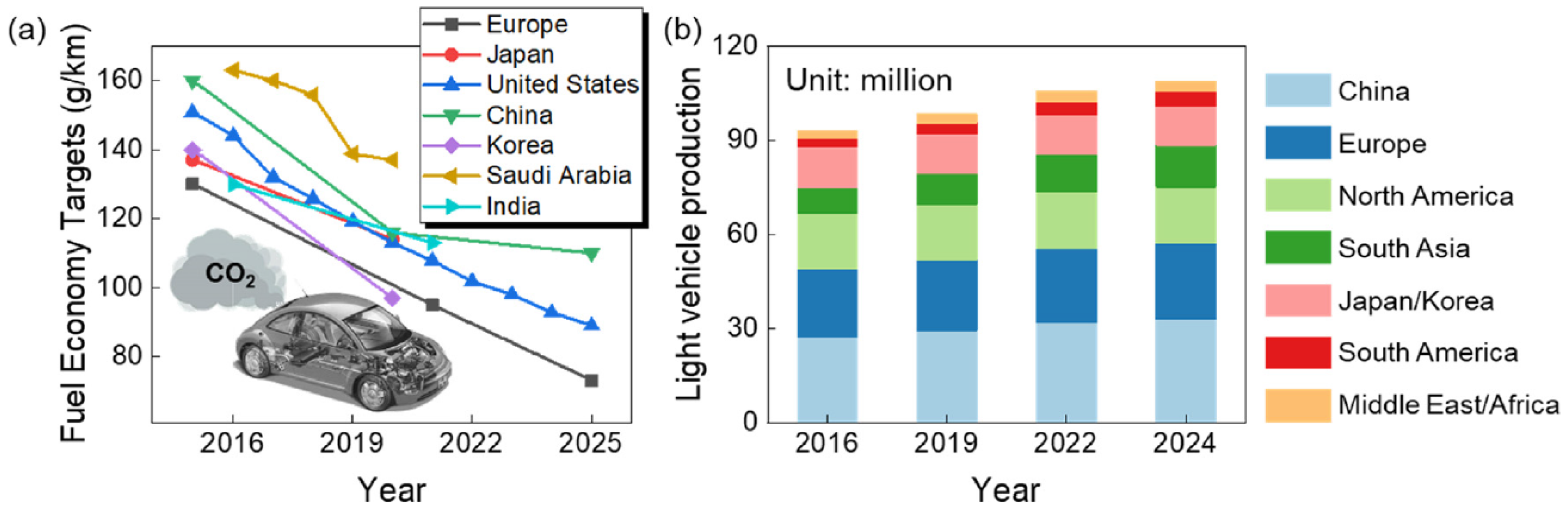
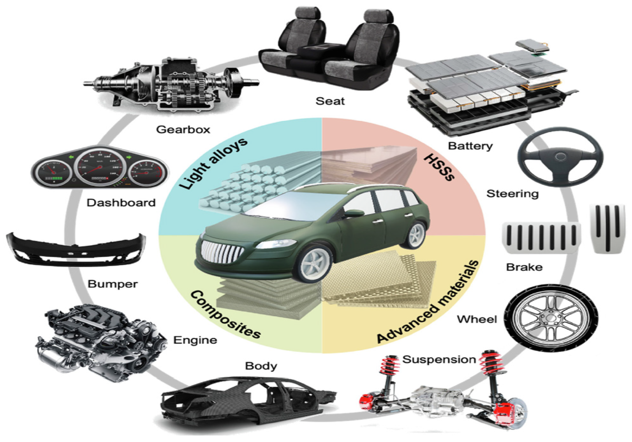
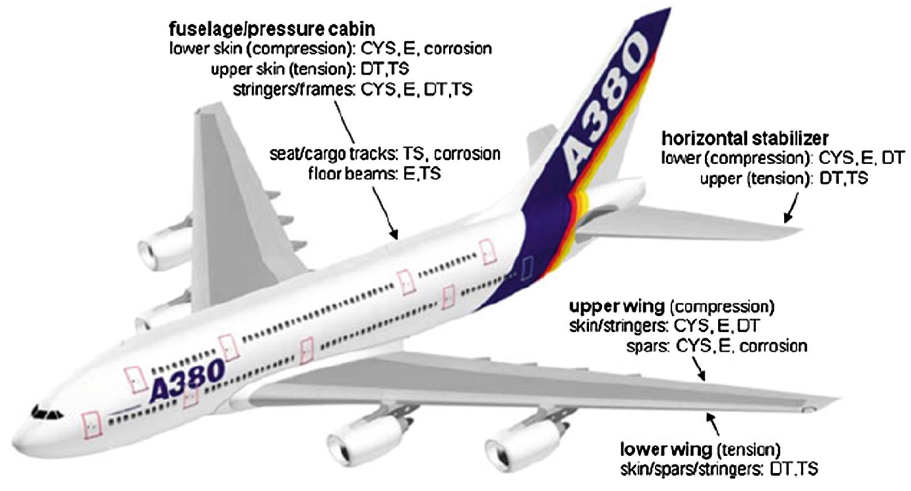
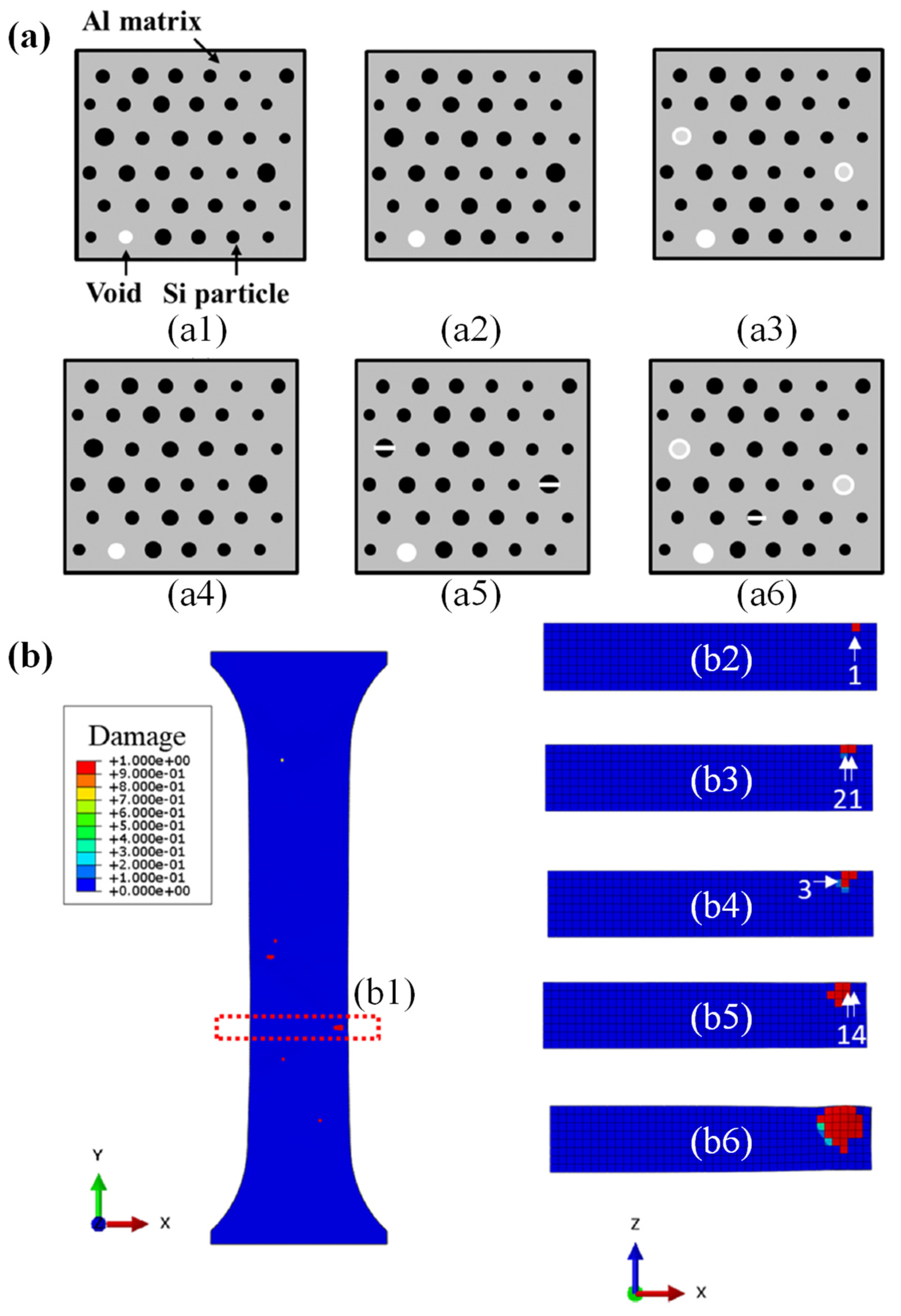
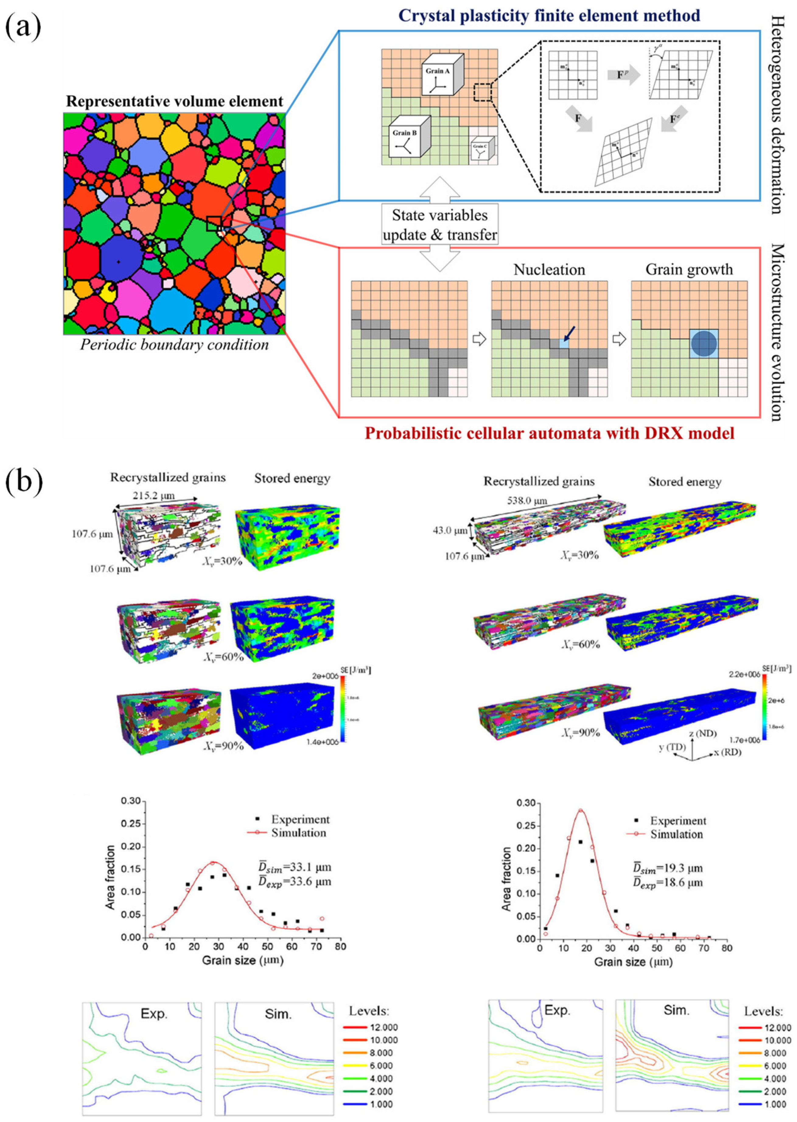
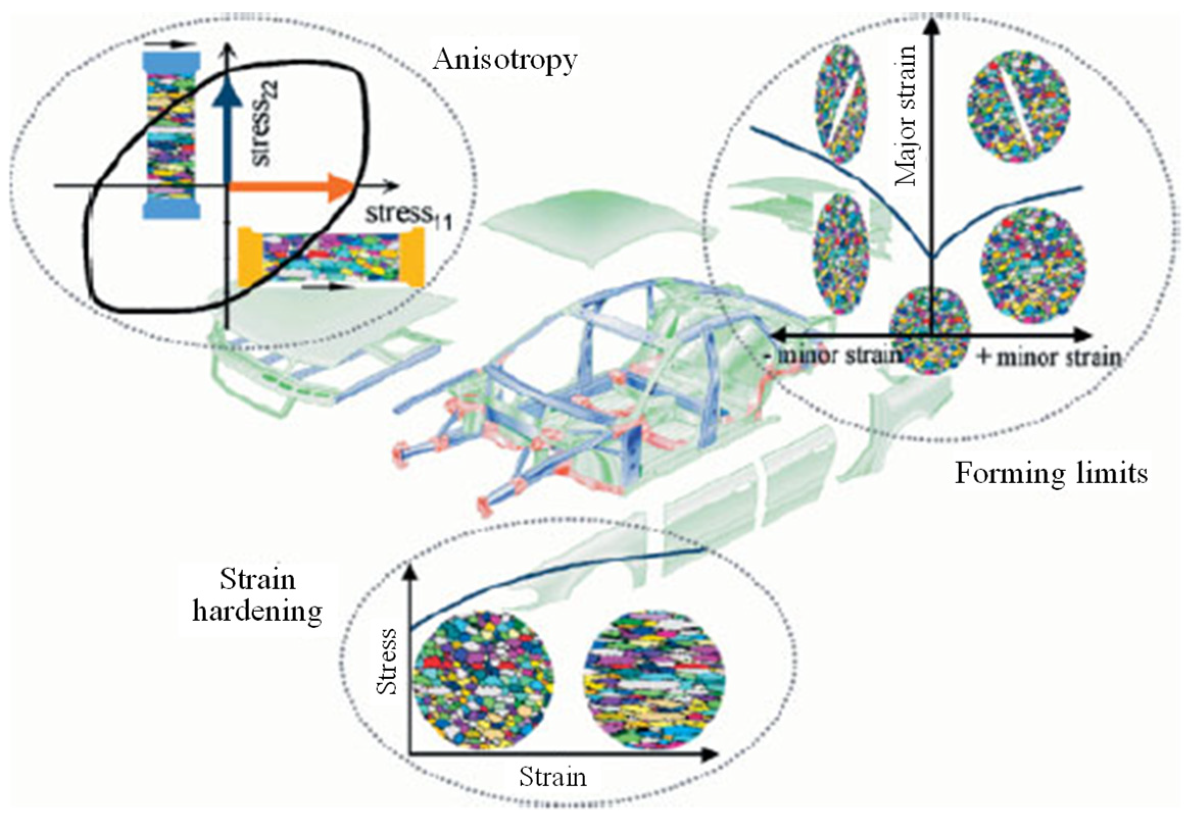
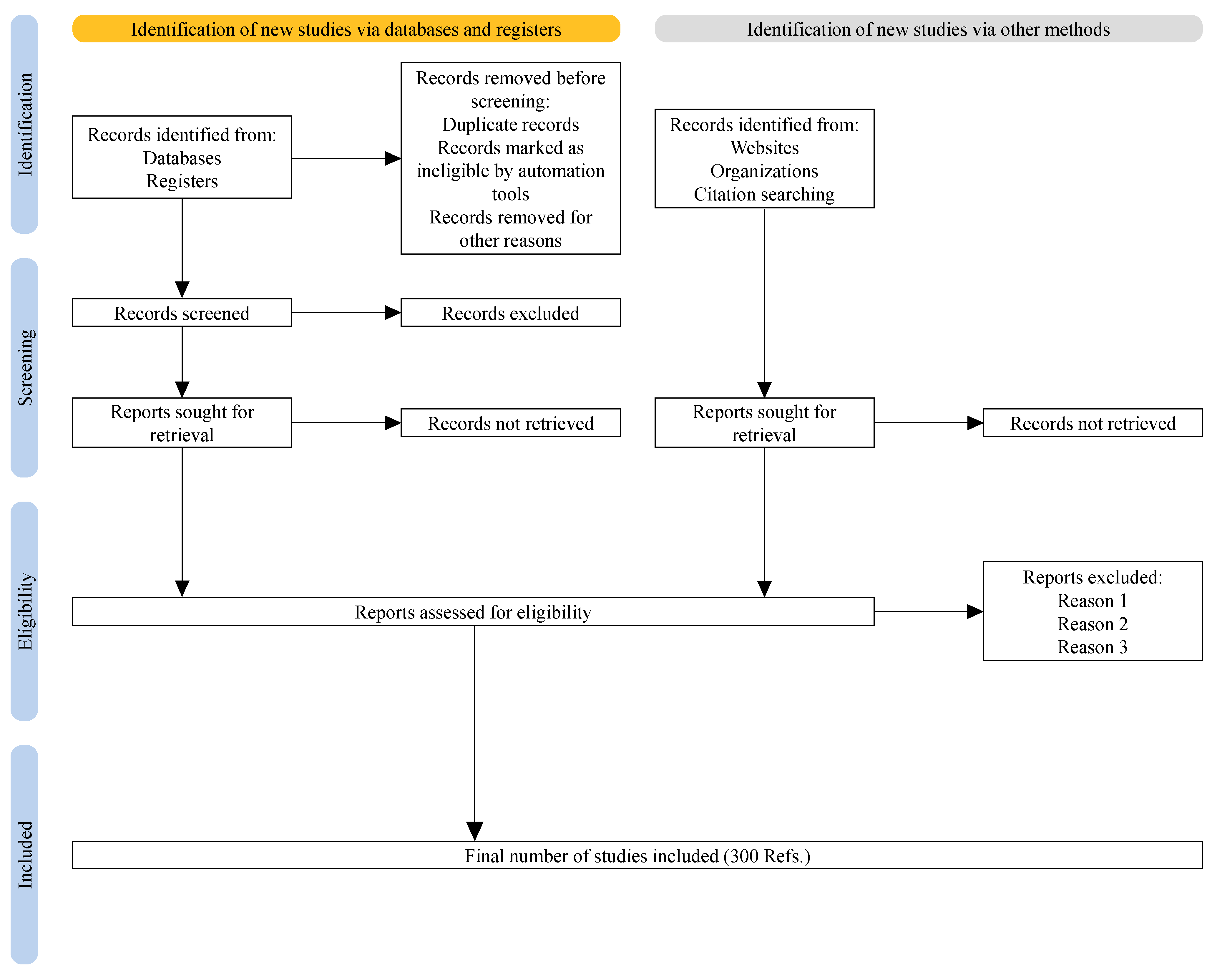
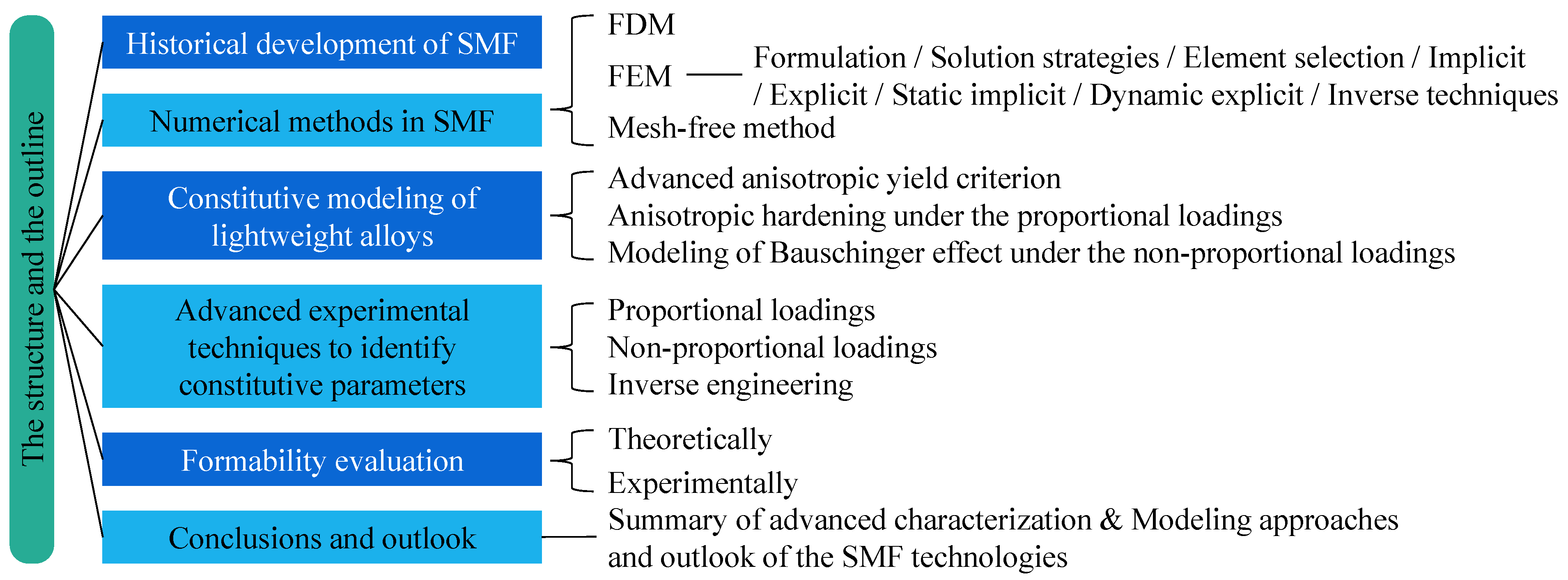
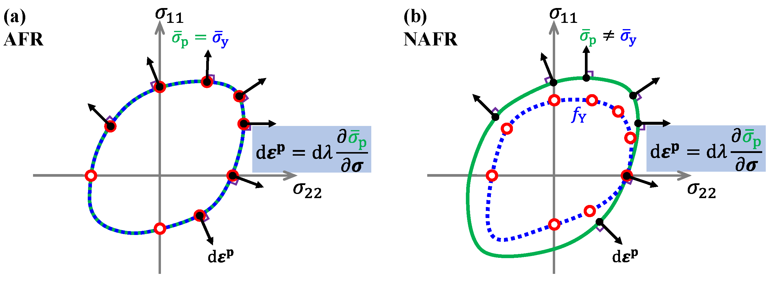
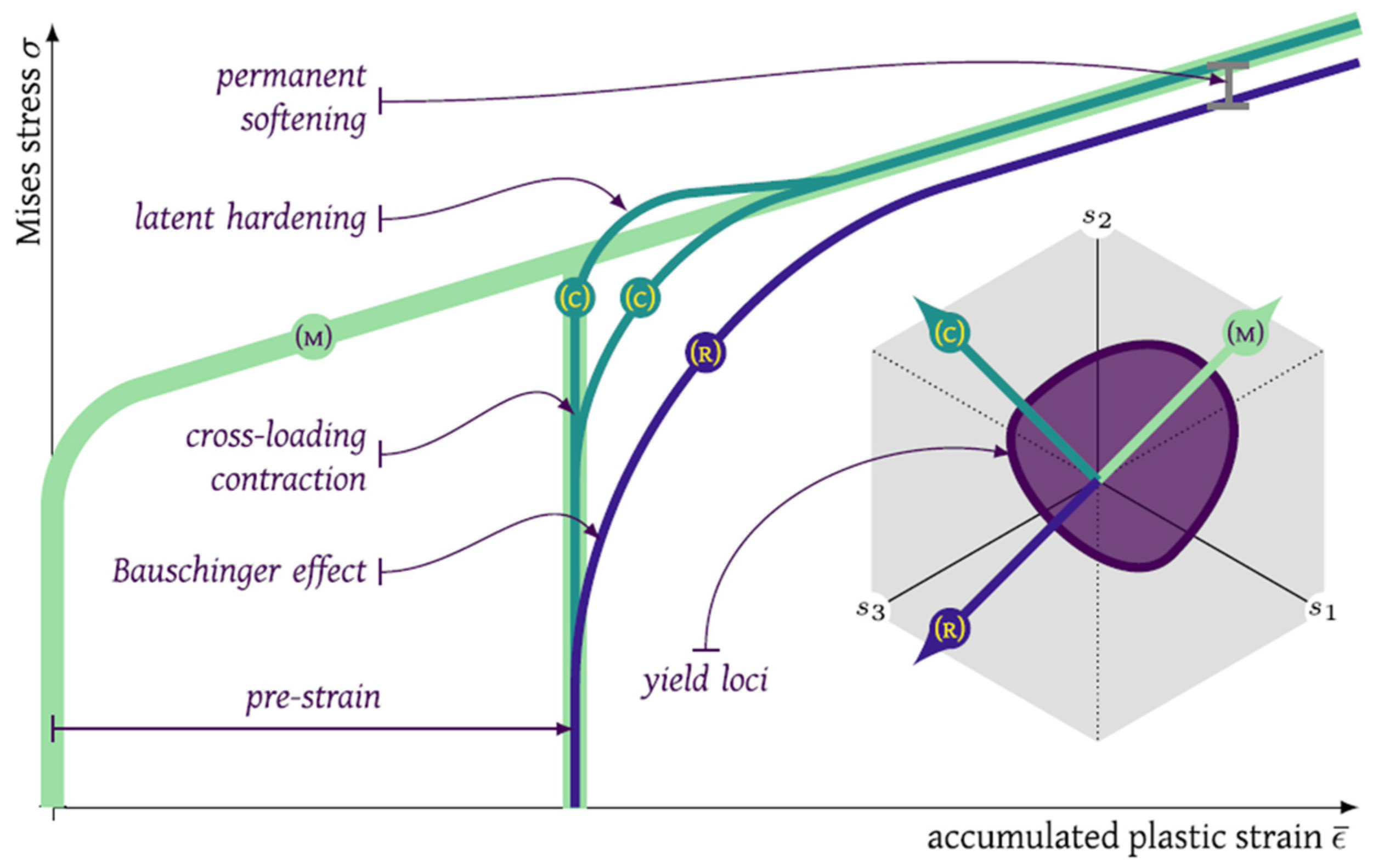
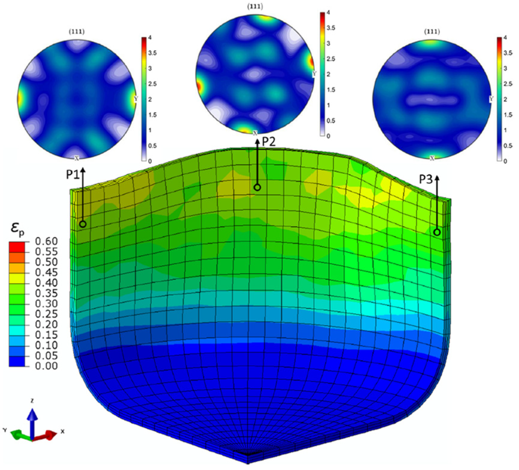
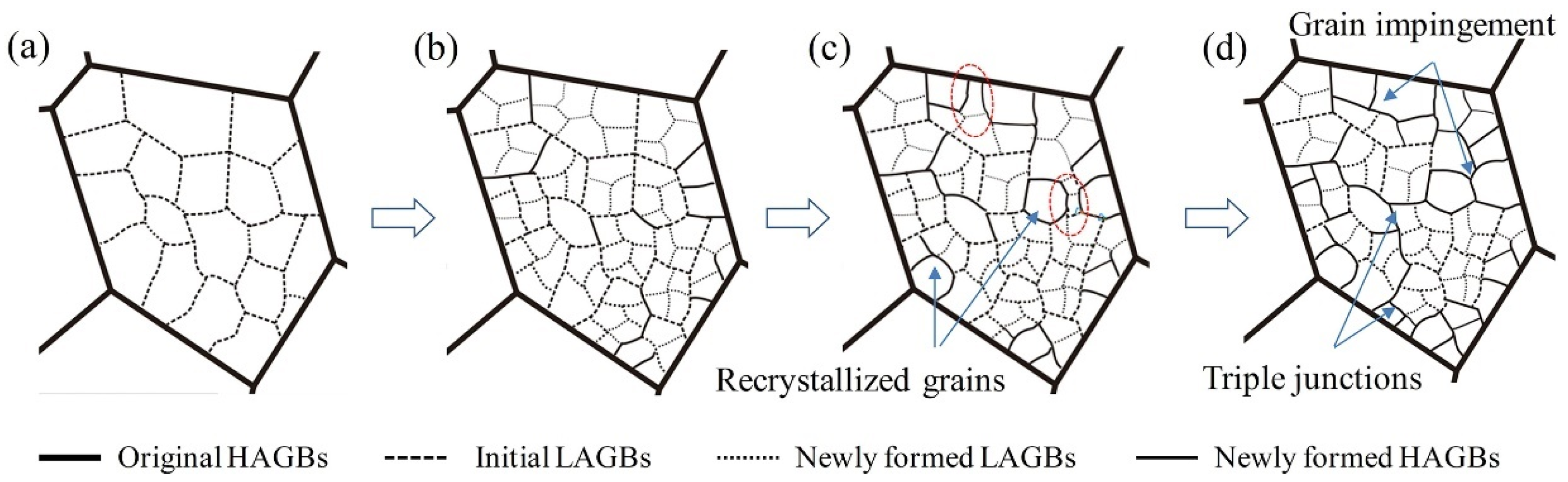
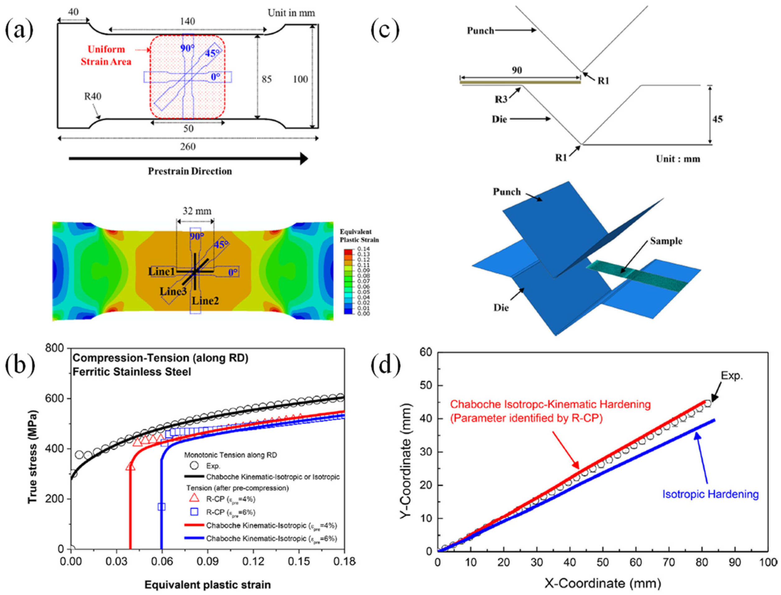
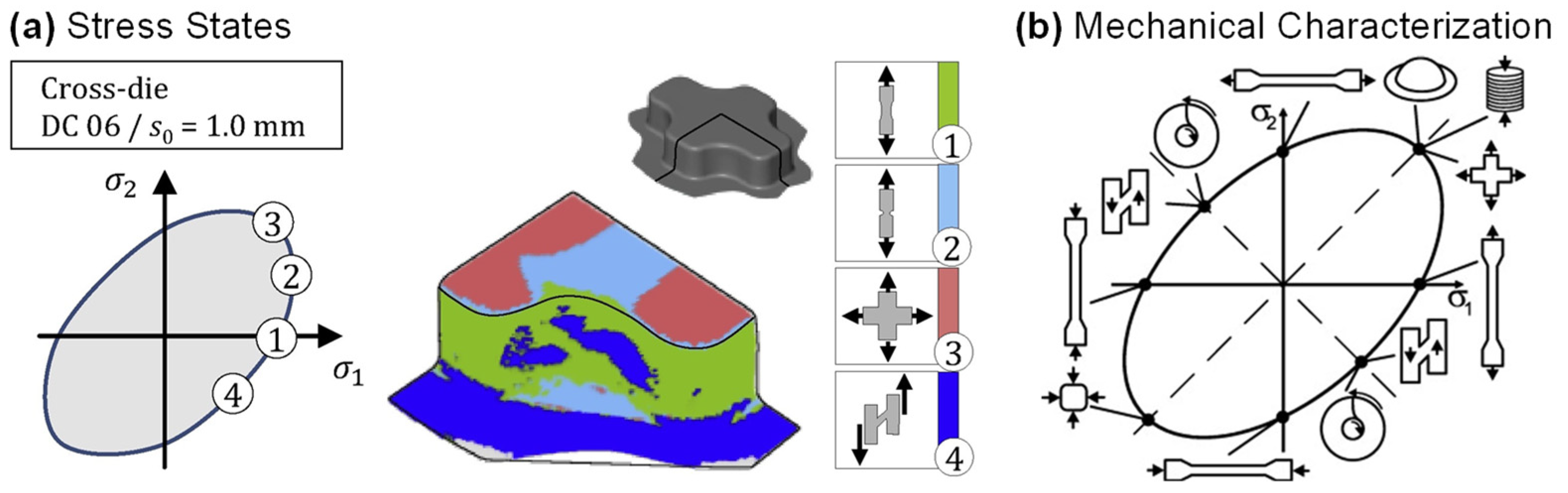
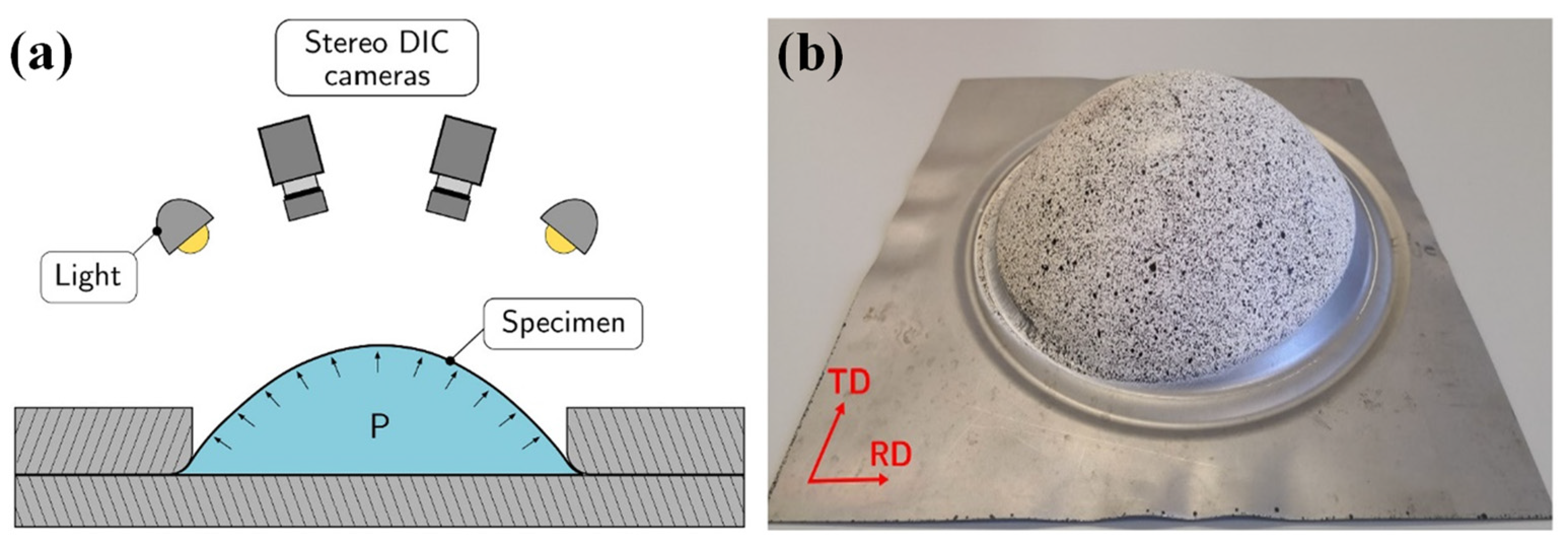
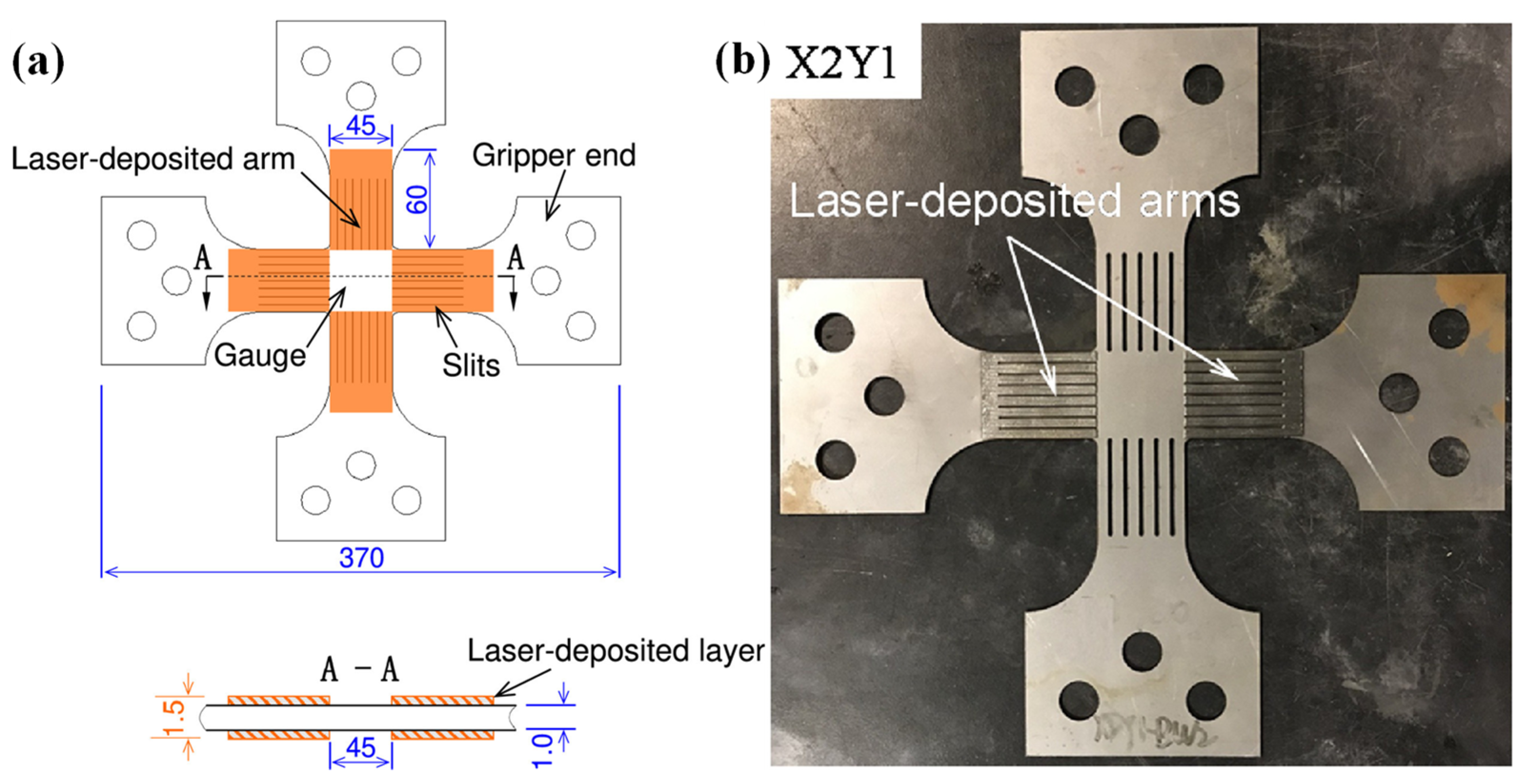
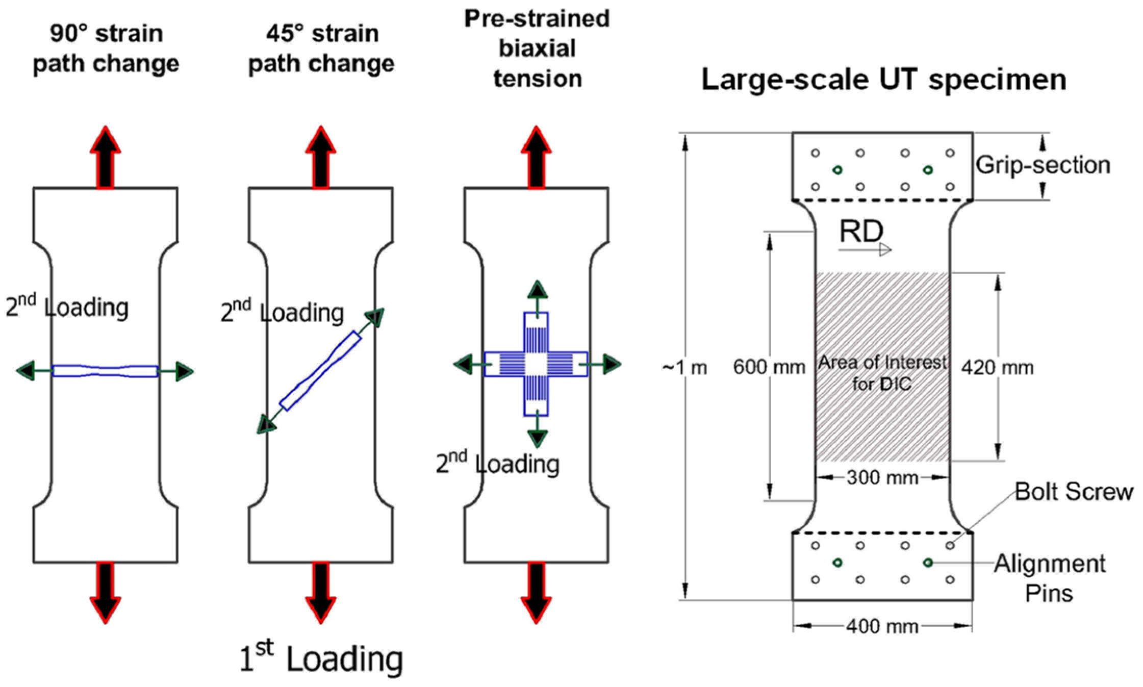
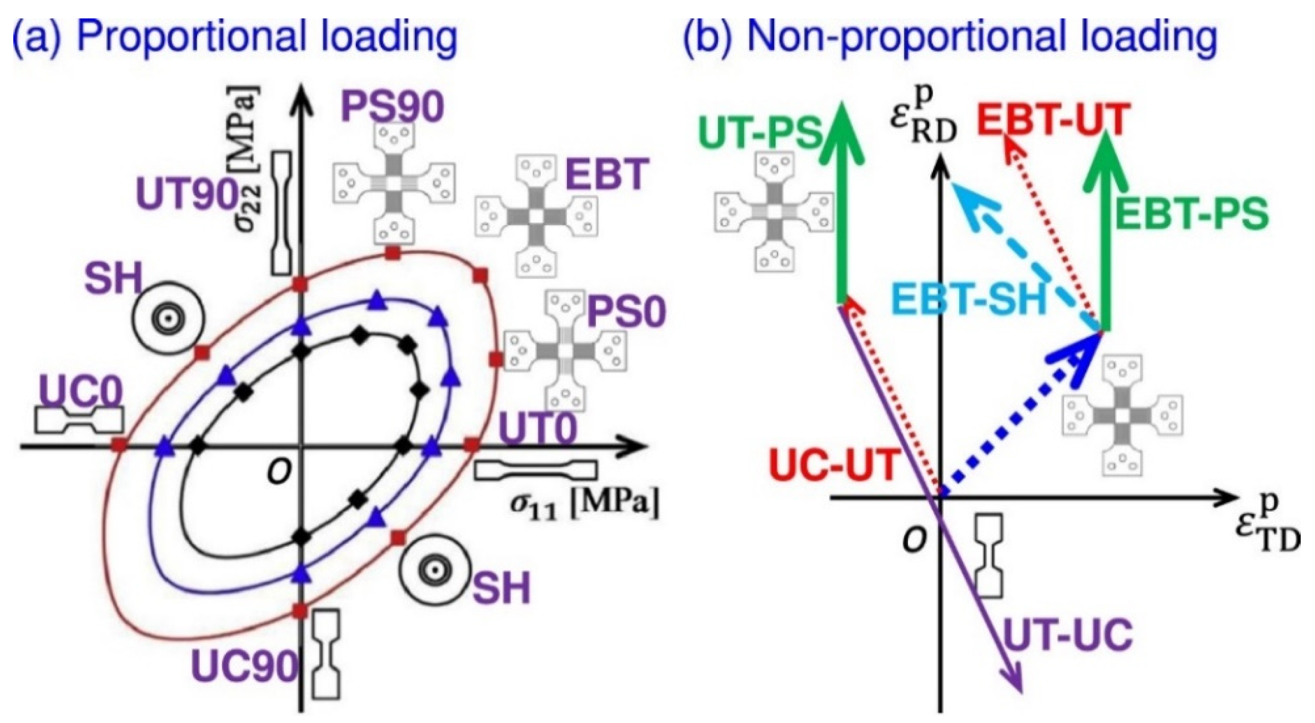
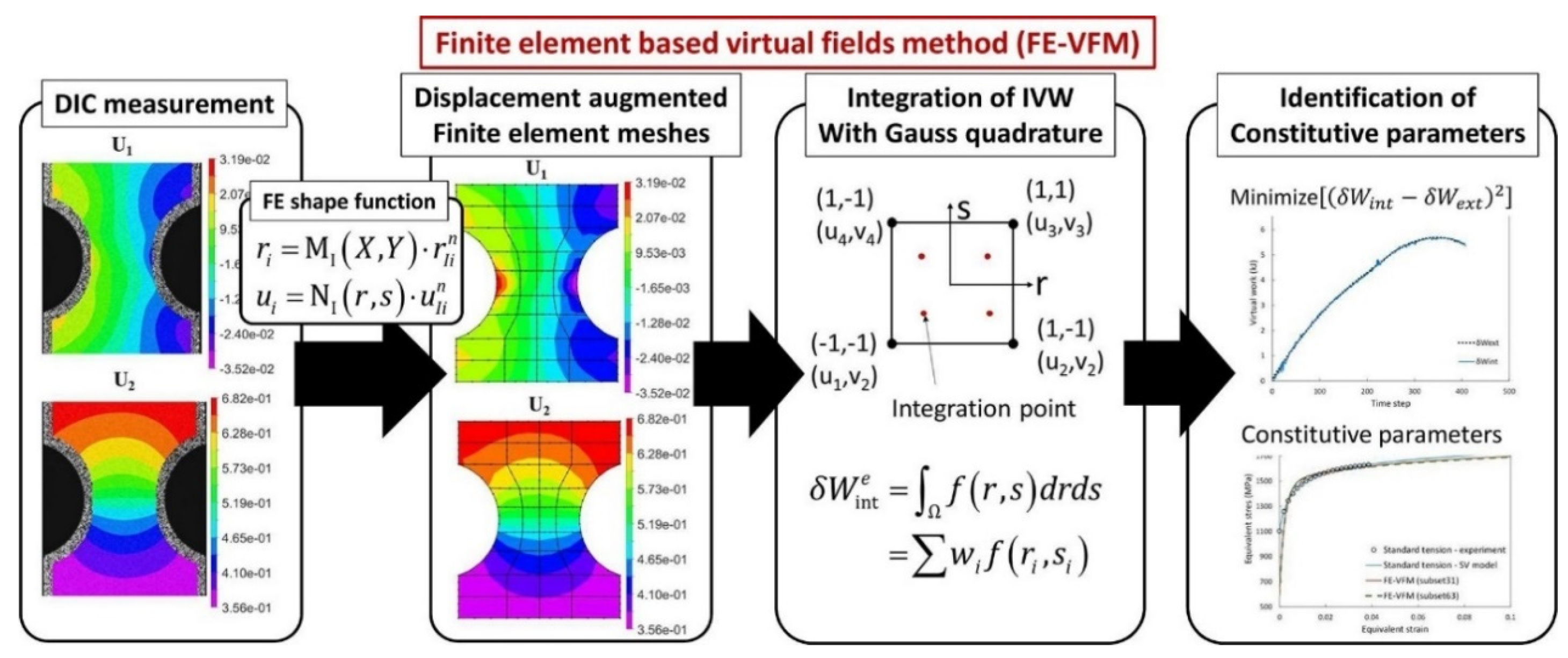
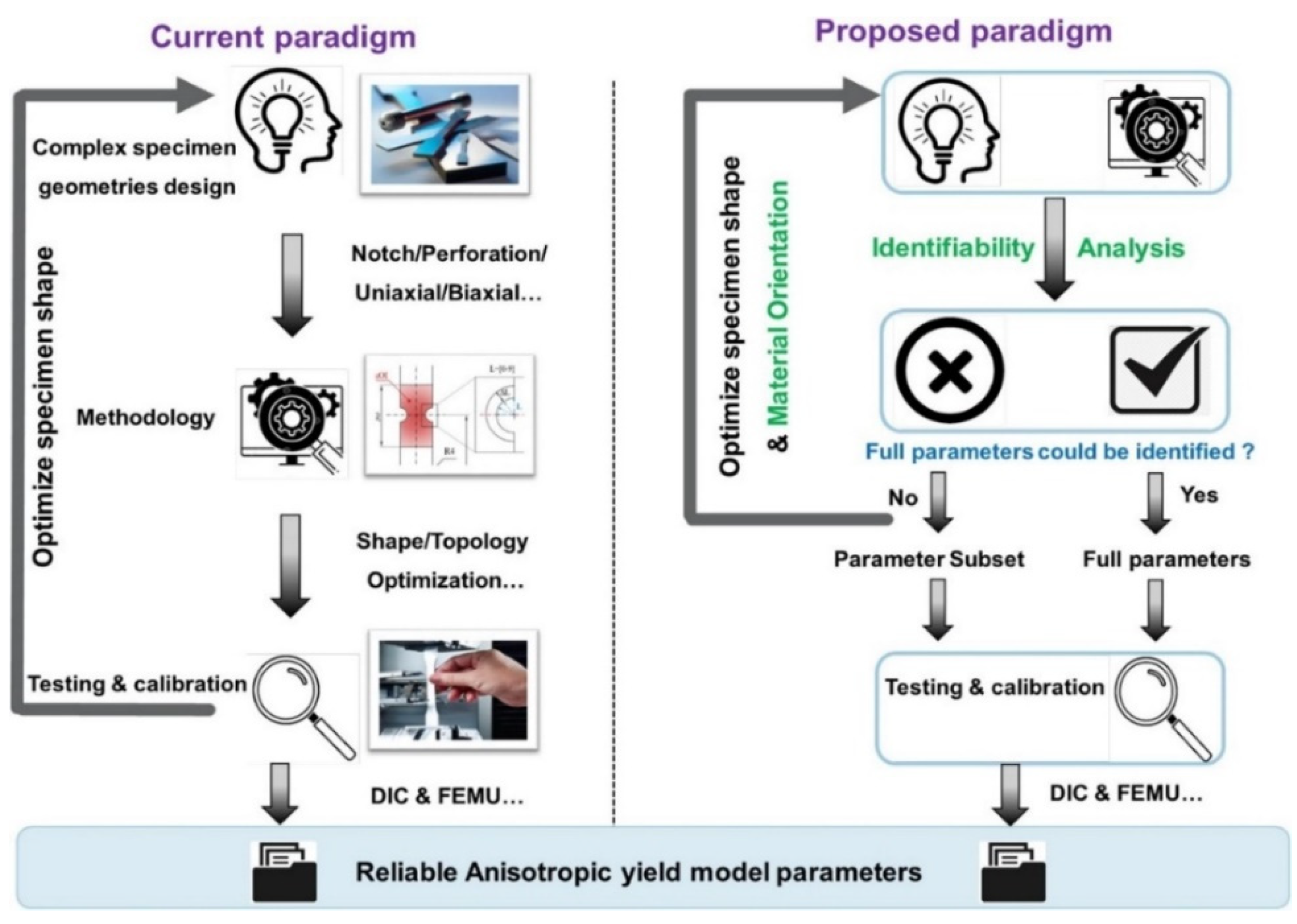
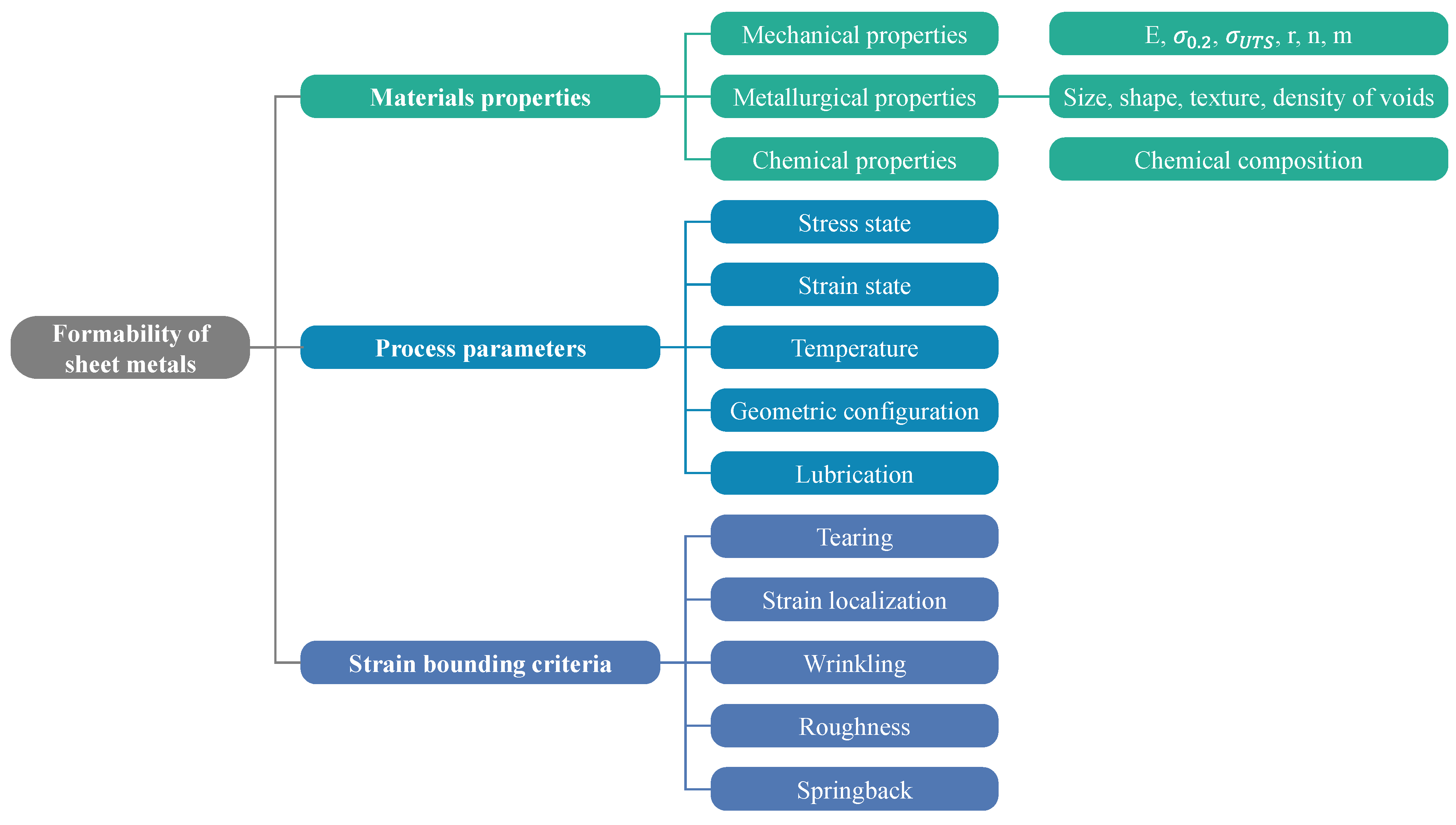
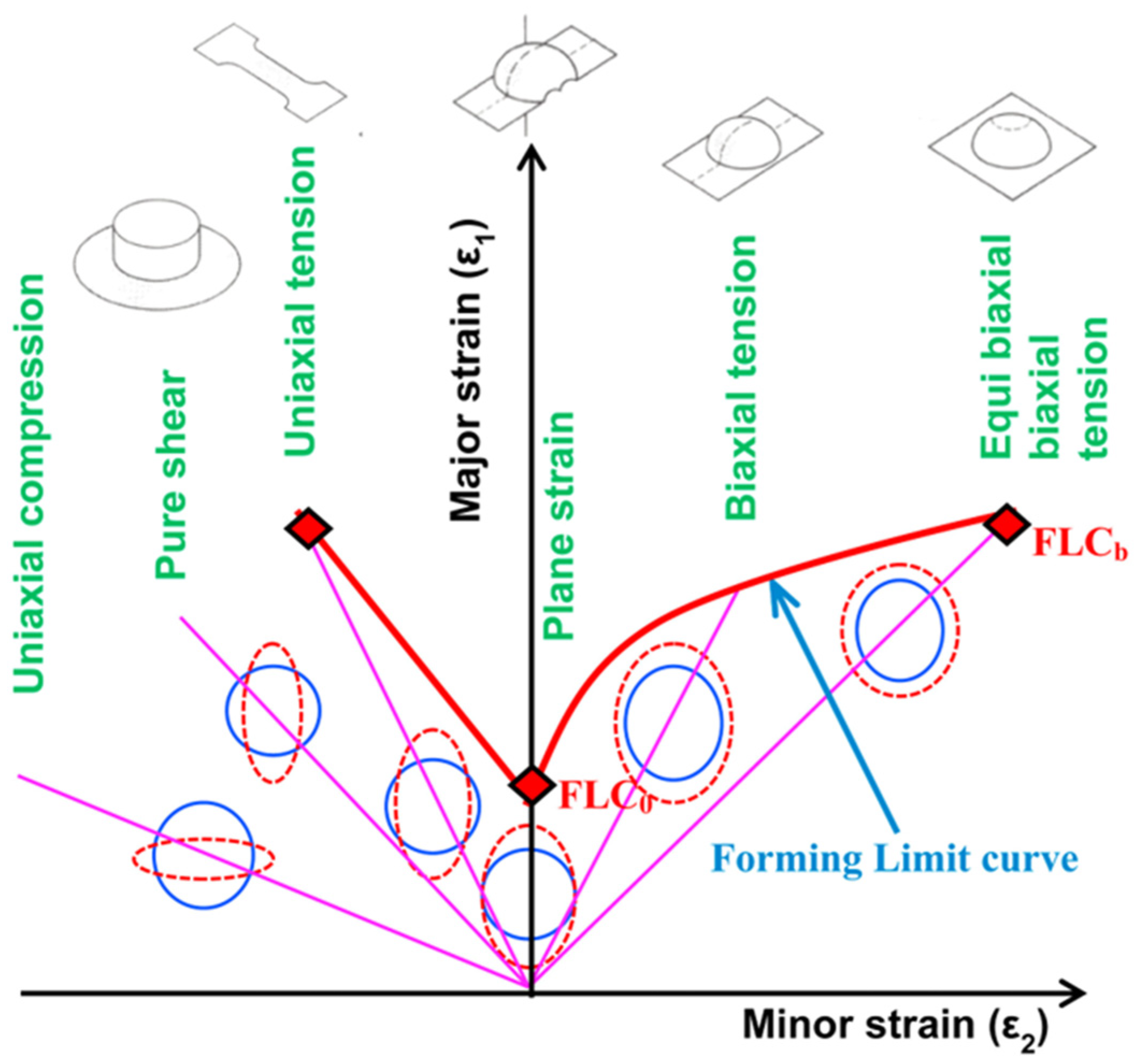
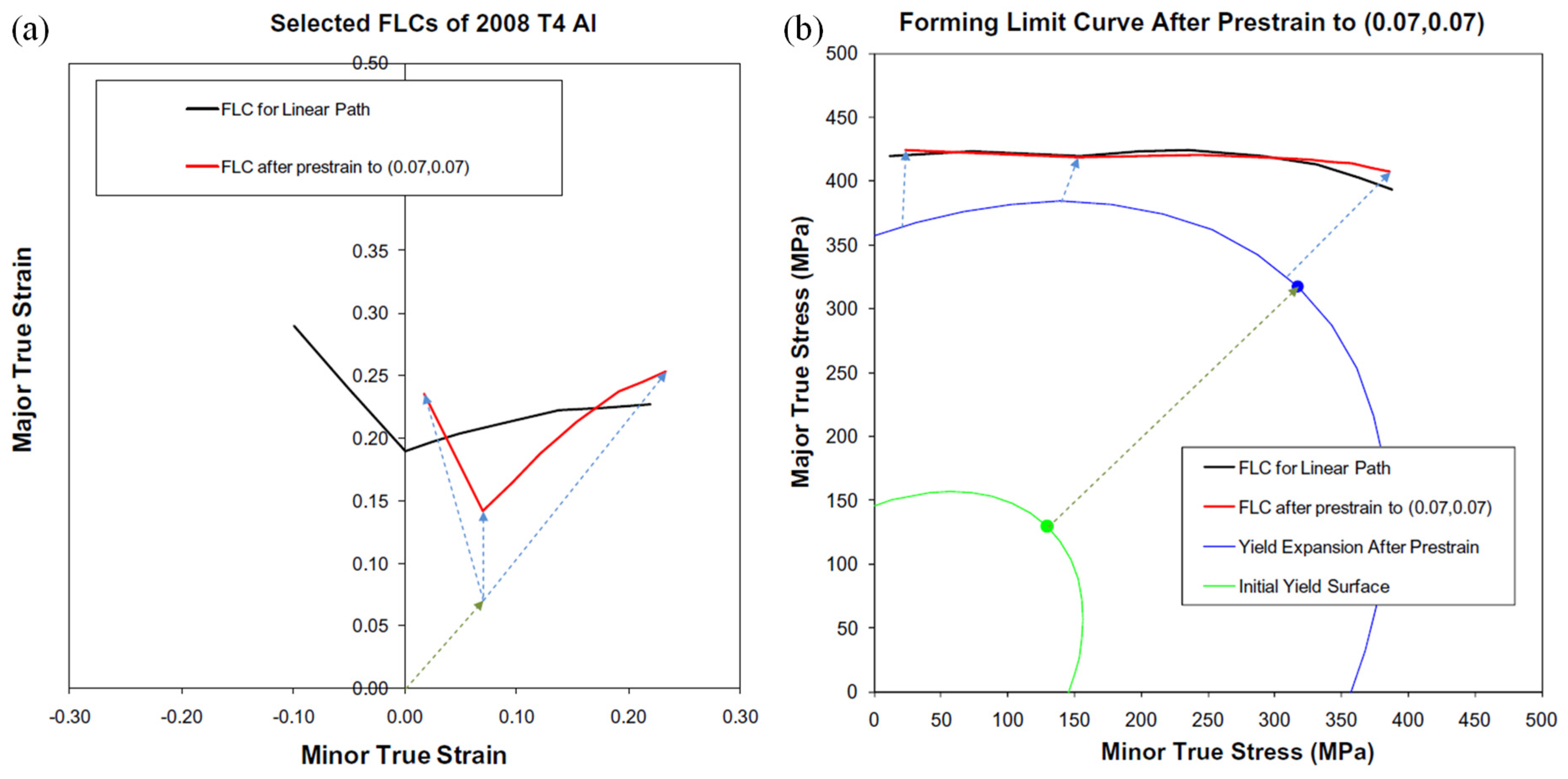
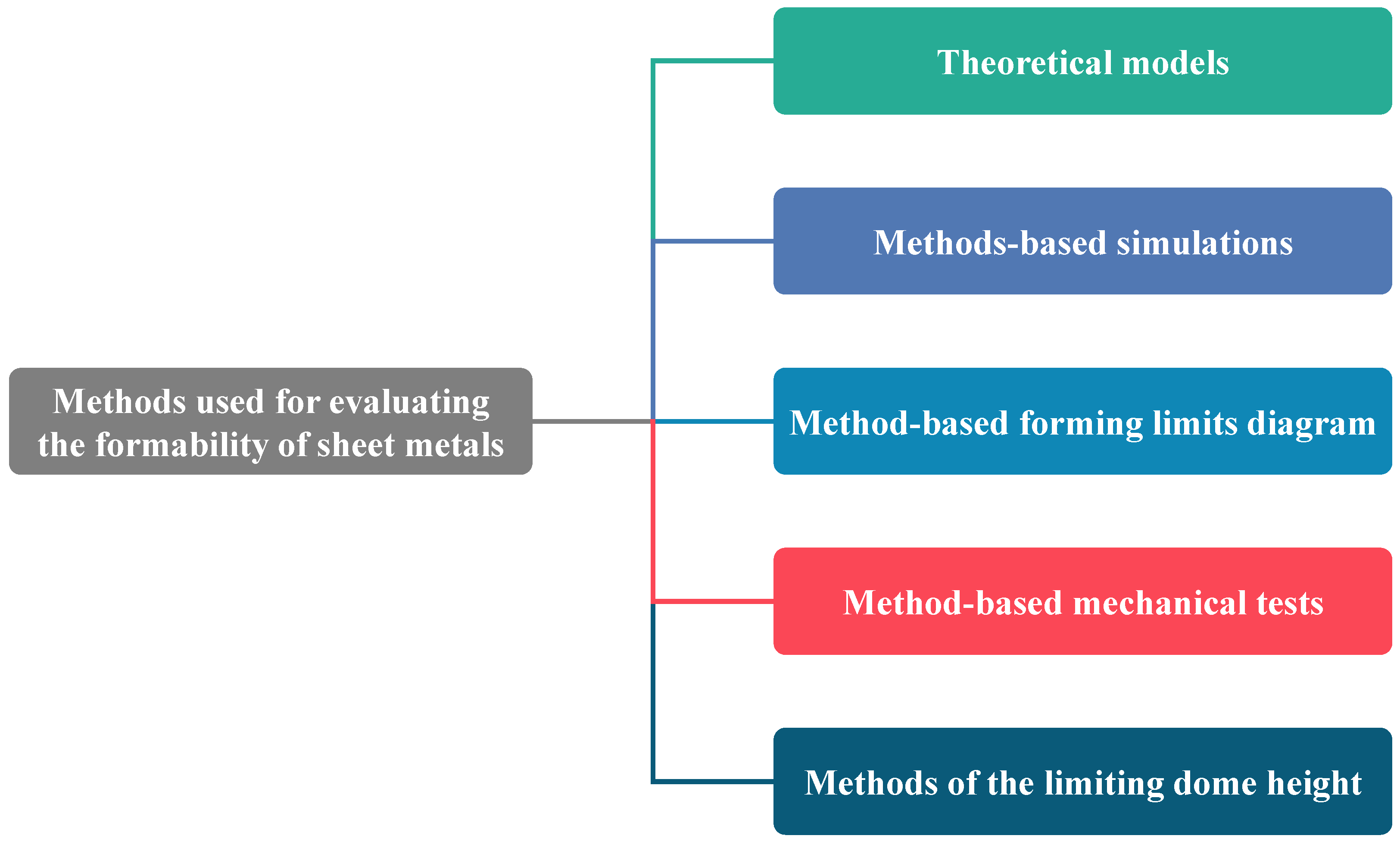
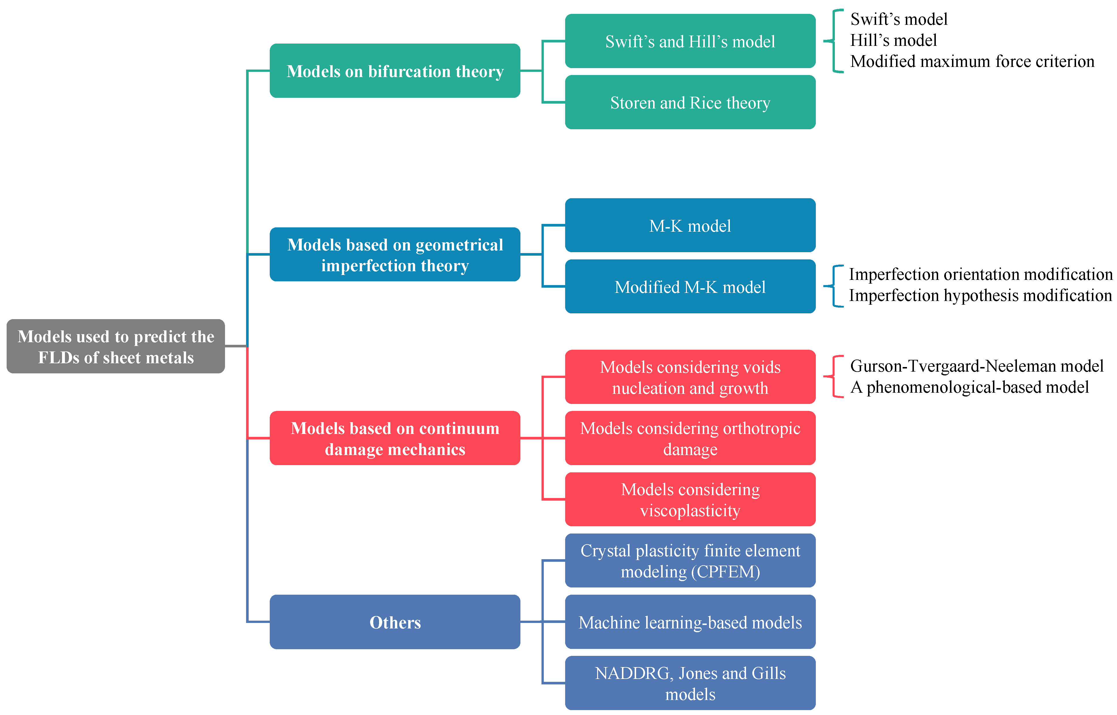
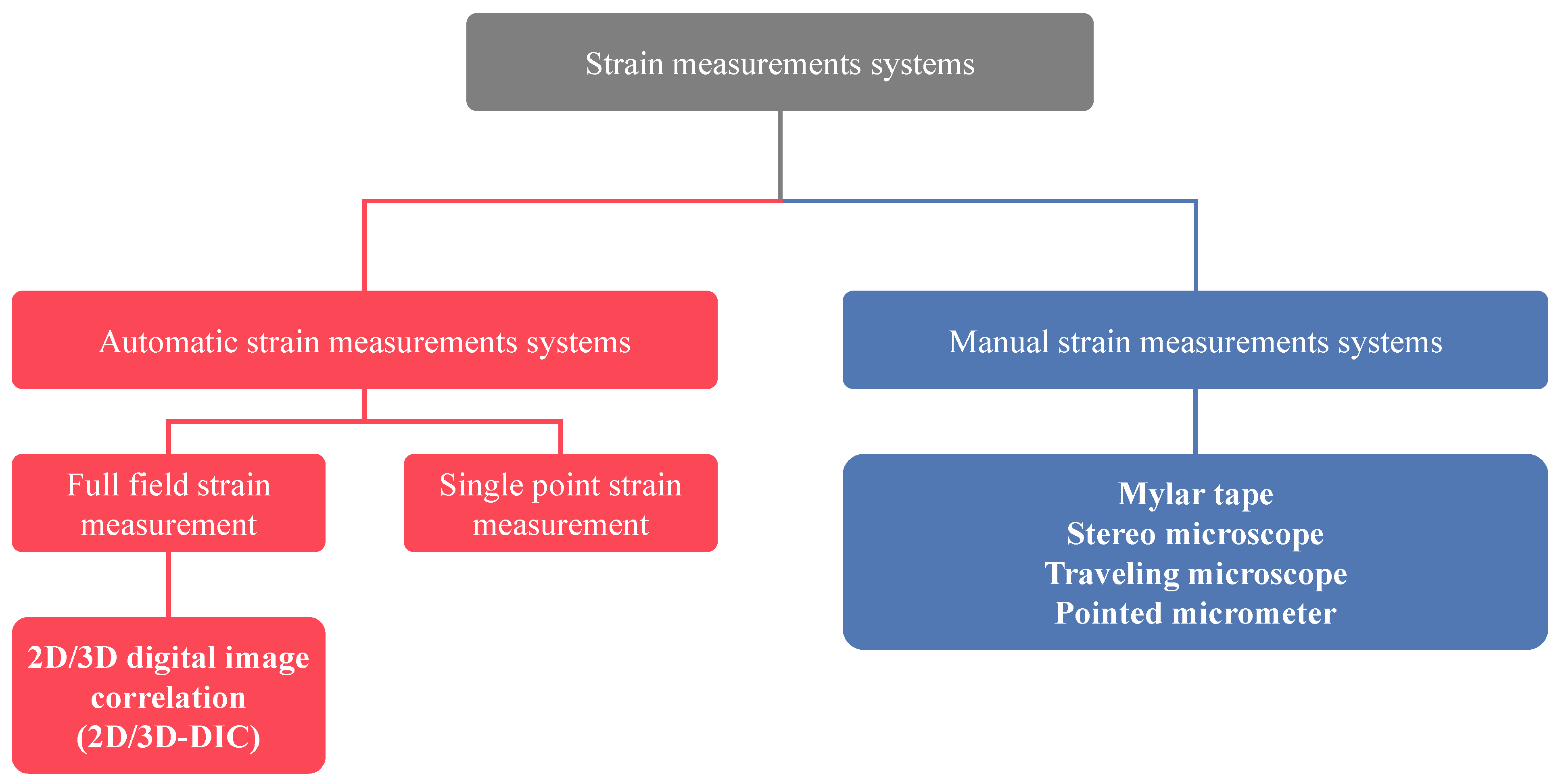
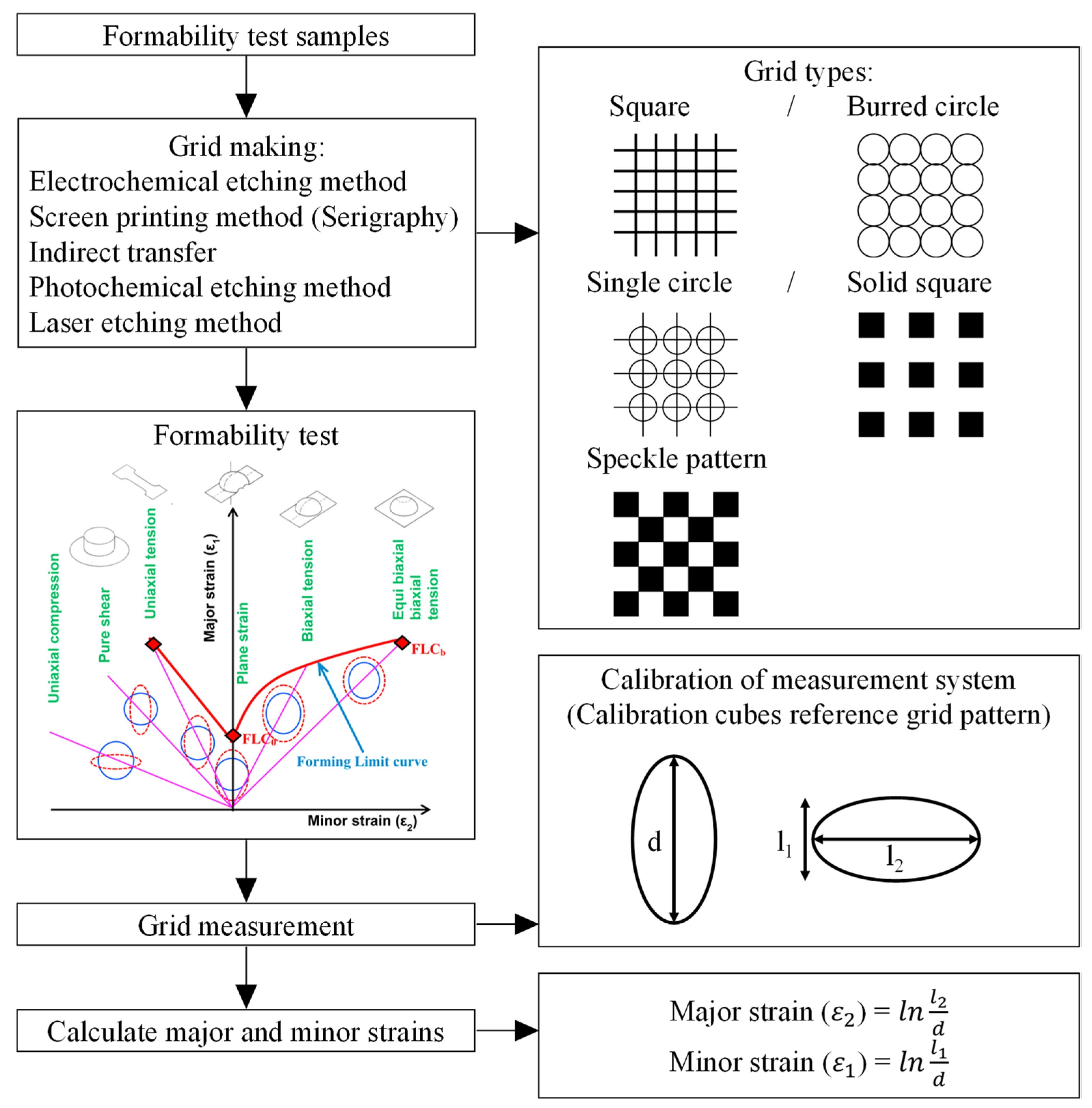
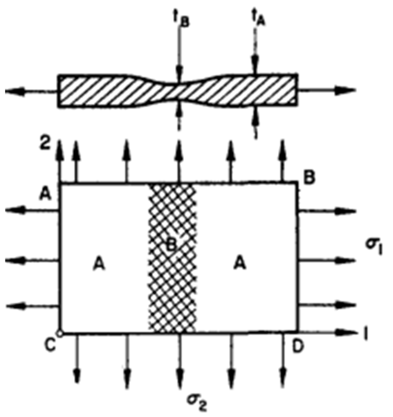
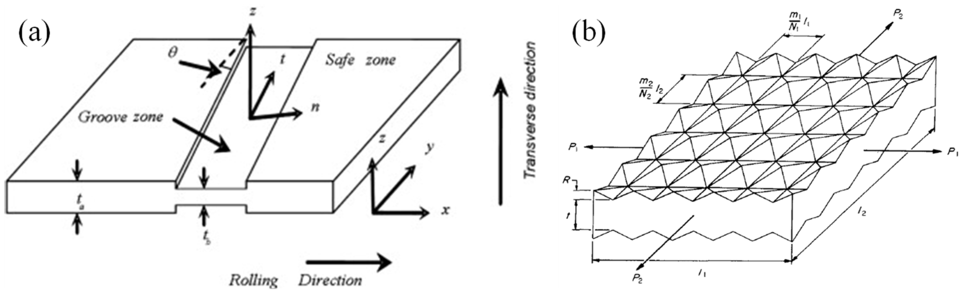
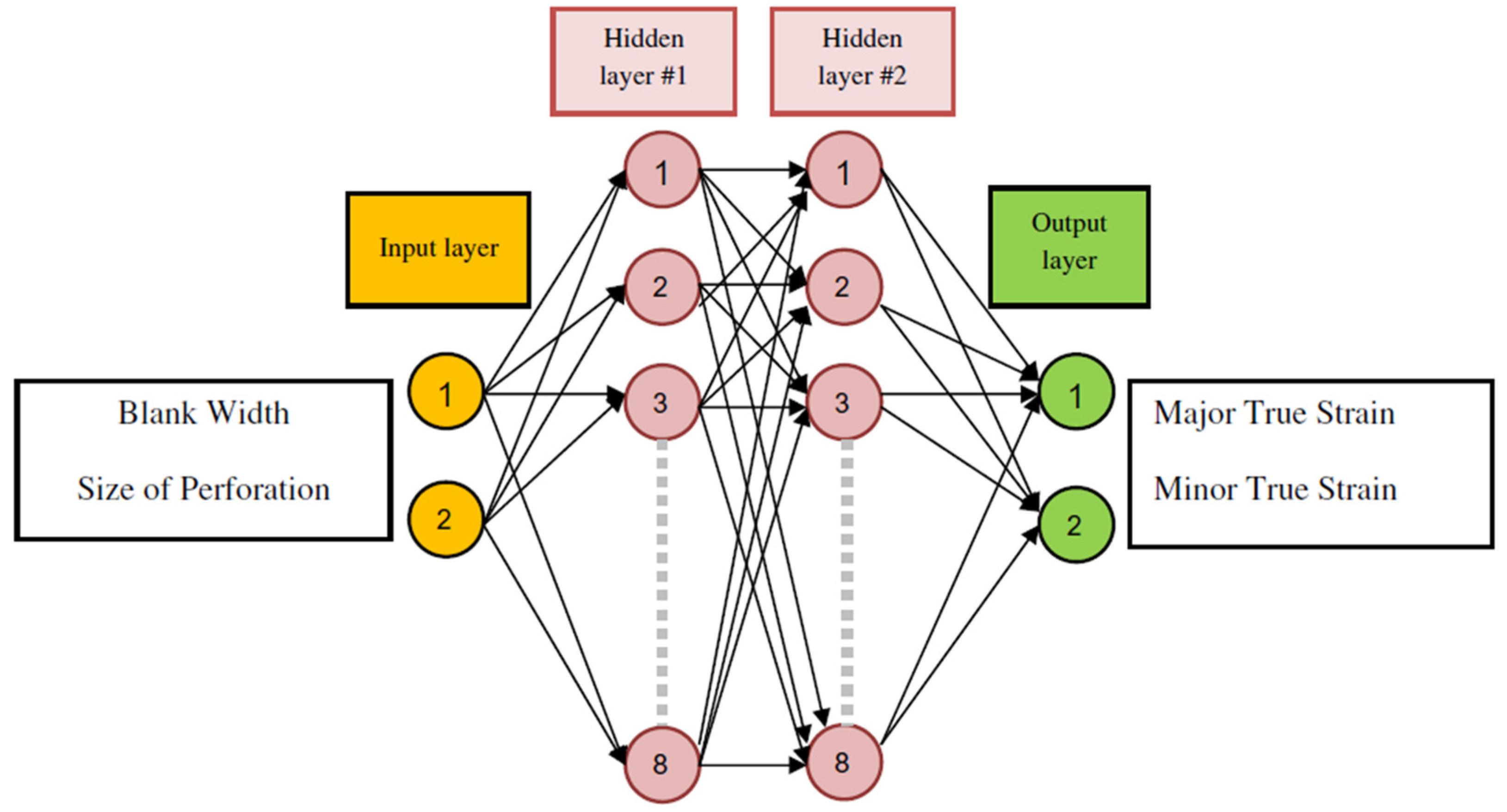
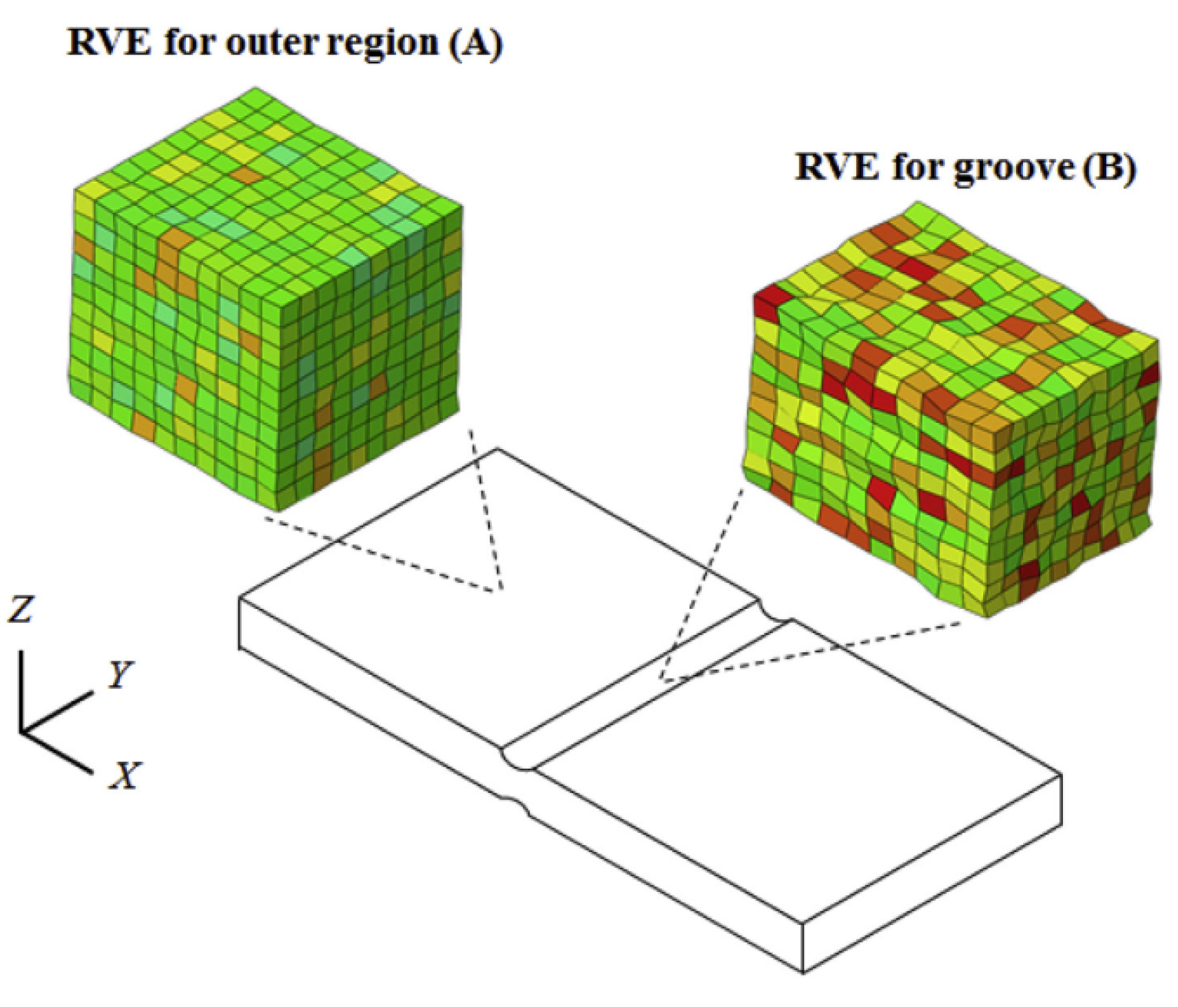
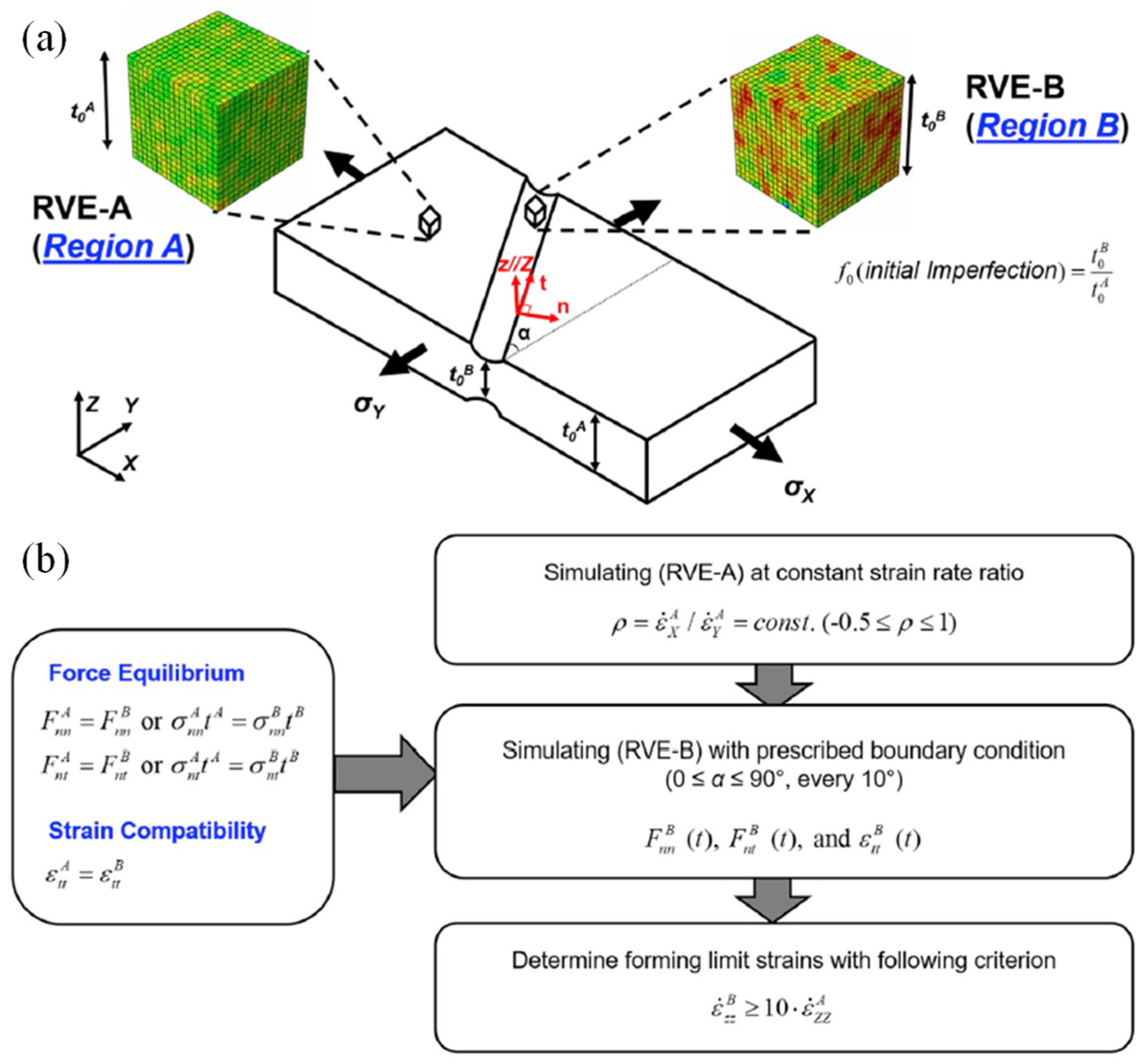
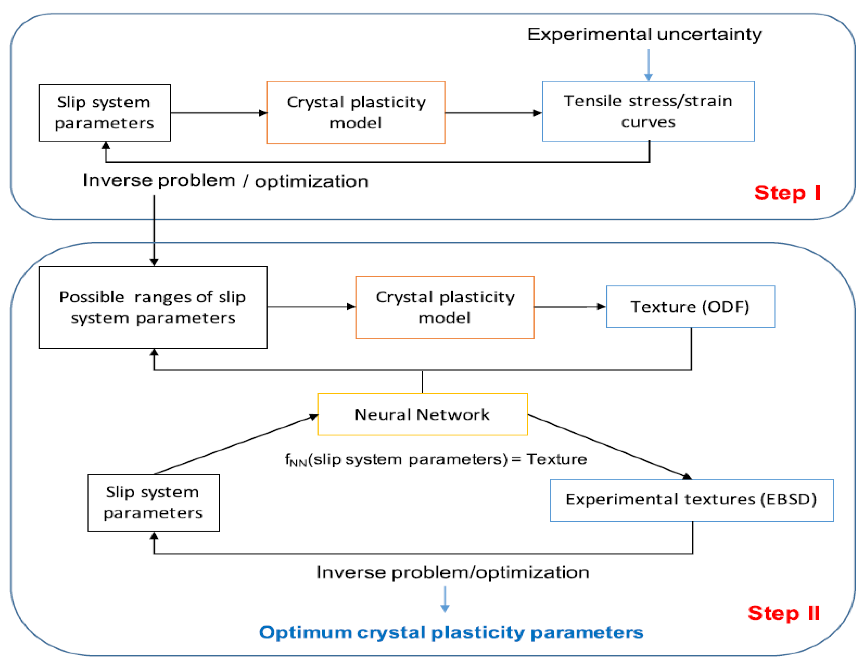
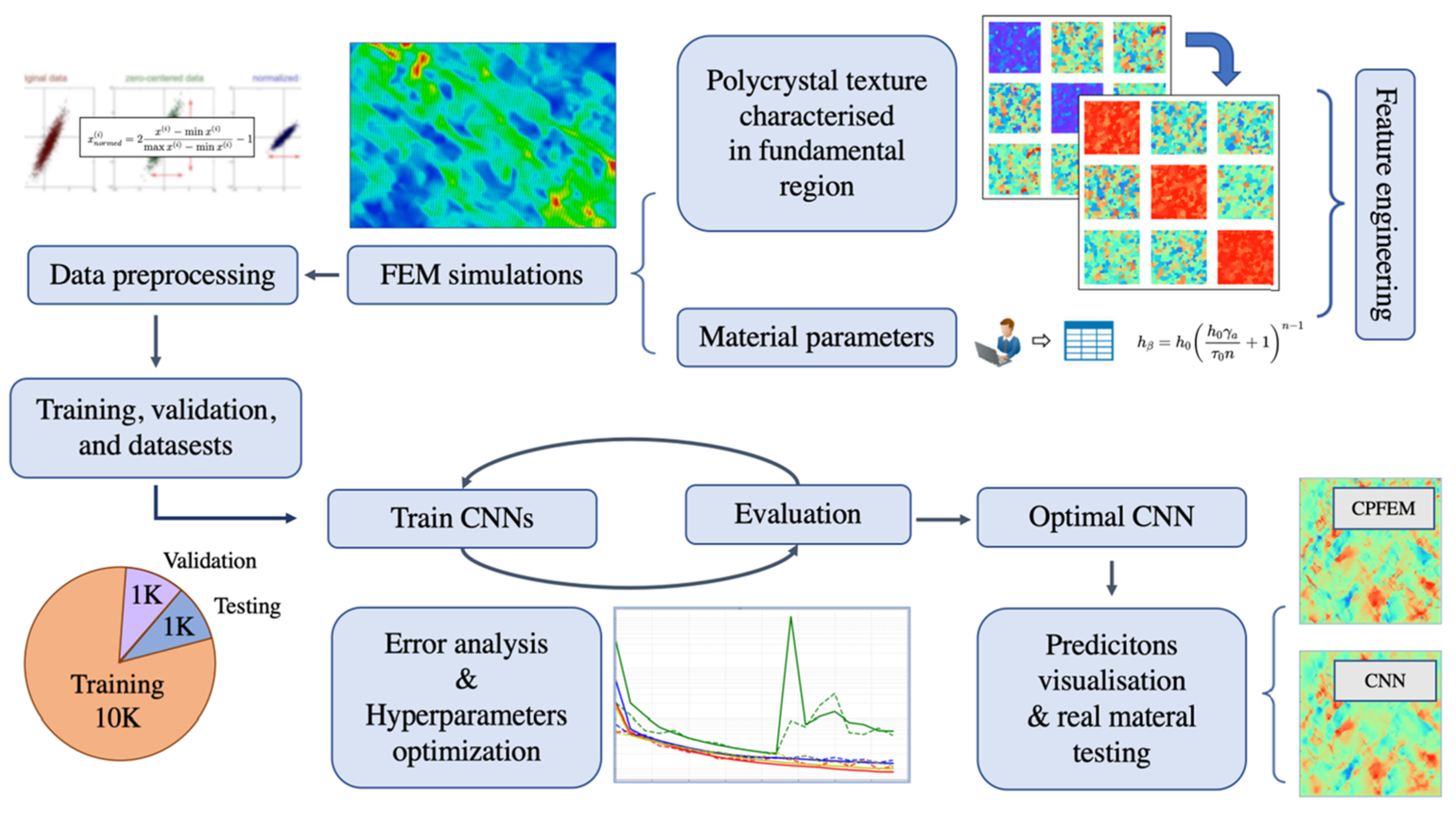
| Lightweight Materials | Typical Components | Examples | |
|---|---|---|---|
| Model | Application | ||
| Al alloys | Shock absorber, brake, piston, tank, wheel rim, fender, roof, door, bumper, heat insulator, handle, piping, steering component, conrod, rotor, suspension component, bonnet, chassis, spoke, valve, gas cylinder, seat frame. | Audi A8 | Chassis |
| Jaguar XE | Monocoque | ||
| Mercedes AMG GT | Body | ||
| Ford F-150 | Body panel | ||
| Toyota GT86 | Bonnet | ||
| Mazda MX-5 | Bumper | ||
| Nissan Leaf | Battery case, sealing component | ||
| Tesla Model S | Frame and heat exchangers | ||
| Mg alloys | Engine block, steering wheel frame, seat frame, instrument panel, wheel rim, cylinder head, clutch case, cylinder block, transmission case, lower crankcase, intake manifold, air intake system, steering link bracing, oil pump body, camshaft drive chain case, gear control housing, bracket. | Ford Thunderbird | Steering wheel frame |
| Chrysler Plymouth | |||
| BMW(MINI) | |||
| Lexus LS430 | |||
| Mercedes Roadster 300/400/500 | SL Seat frame | ||
| Lexus LS430 | |||
| Chrysler Jeep | Instrument panel | ||
| Audi A8 | |||
| Toyota Century | |||
| Toyota 2000GT | Wheel rim | ||
| Toyota Supra | |||
| Alfa Romeo GTV | |||
| Porsche AG 911 | |||
| Dodge Raw | Cylinder head | ||
| Volvo Motors (LCP) | |||
| Honda Motor | |||
| Volkswagen Passat | Transmission case | ||
| Audi A4, A6 | |||
| Porsche AG 911 | |||
| Ti alloys | Connecting rod, engine valve, spring, intake valve, wheel, turbocharger, exhaust system, muffler, body frame, engine rocker arm, suspension component, engine piston pin, fastener, lug nut, door penetration beam, car stop bracket, brake caliper piston, pin bolt, pressure plate, shift button, clutch circle, fuel tank, fuel cell separator. | Mercedes-Benz S-class | Brake guide pin |
| Volkswagen | Sealing washer (brake) | ||
| Honda S2000 Roadster | Gear shift knob | ||
| Porsche GT3 | Connecting rod | ||
| Toyota Altezza 6cyL | Valve | ||
| Nissan Infinity Q45 | |||
| Mercedes-Benz truck | Turbocharger rotor | ||
| Mitsubishi Lancer | |||
| GM Corvette Z06 | Exhaust system | ||
| Acura NSX | Engine | ||
| Volkswagen Lupo FSI | Suspension spring | ||
| Reference | Non-Quadratic | SD Effect | Analytical Calibration |
|---|---|---|---|
| Stoughton (& Yoon) [146,148] | × | × | √ |
| Stoughton & Yoon [147] | × | √ | √ |
| Min et al. [149] | √ | × | √ |
| Lee et al. [150] | √ | × | √ |
| Chen et al. [154] | √ | × | √ |
| Park et al. [151] | √ | √ | √ |
| Hou et al. [155] | √ | √ | √ |
| Hu et al. [156] | √ | √ | √ |
| Lou et al. [153] | √ | √ | √ |
| Modelling Strategy | Back Stress | Change of Yield Surface Shape | References |
|---|---|---|---|
| Kinematic hardening | √ | × | [167,168,169,170,172,173,174,175,193] |
| Distortional hardening | × | √ | [166,176,177,178,179,180,181,183,184,186,187,194] |
| Combined hardening | √ | √ | [188,189,190,191,192,195,196,197,198] |
Disclaimer/Publisher’s Note: The statements, opinions and data contained in all publications are solely those of the individual author(s) and contributor(s) and not of MDPI and/or the editor(s). MDPI and/or the editor(s) disclaim responsibility for any injury to people or property resulting from any ideas, methods, instructions or products referred to in the content. |
© 2023 by the authors. Licensee MDPI, Basel, Switzerland. This article is an open access article distributed under the terms and conditions of the Creative Commons Attribution (CC BY) license (https://creativecommons.org/licenses/by/4.0/).
Share and Cite
Hou, Y.; Myung, D.; Park, J.K.; Min, J.; Lee, H.-R.; El-Aty, A.A.; Lee, M.-G. A Review of Characterization and Modelling Approaches for Sheet Metal Forming of Lightweight Metallic Materials. Materials 2023, 16, 836. https://doi.org/10.3390/ma16020836
Hou Y, Myung D, Park JK, Min J, Lee H-R, El-Aty AA, Lee M-G. A Review of Characterization and Modelling Approaches for Sheet Metal Forming of Lightweight Metallic Materials. Materials. 2023; 16(2):836. https://doi.org/10.3390/ma16020836
Chicago/Turabian StyleHou, Yong, Dongjoon Myung, Jong Kyu Park, Junying Min, Hyung-Rim Lee, Ali Abd El-Aty, and Myoung-Gyu Lee. 2023. "A Review of Characterization and Modelling Approaches for Sheet Metal Forming of Lightweight Metallic Materials" Materials 16, no. 2: 836. https://doi.org/10.3390/ma16020836