Effect of Cu-Sn Addition on Corrosion Property of Pressureless Sintered Fe-Cu-Co Substrate Alloys


Abstract
:1. Introduction
2. Material Preparation and Research Methods
3. Results and Analysis
4. Conclusions
Author Contributions
Funding
Institutional Review Board Statement
Informed Consent Statement
Data Availability Statement
Acknowledgments
Conflicts of Interest
References
- Oliveira, F.A.C.; Anjinho, C.A.; Coelho, A.; Amaral, P.M.; Coelho, M. PM materials selection: The key for improved performance of diamond tools. Met. Powder Rep. 2017, 72, 339–344. [Google Scholar] [CrossRef]
- Zhang, L. Filler metals, brazing processing and reliability for diamond tools brazing: A review. J. Manuf. Process. 2021, 66, 651–668. [Google Scholar] [CrossRef]
- Li, J.; Fang, W.; Wan, L.; Liu, X.; Hu, W.; Cao, D.; Han, K.; Li, Y.; Yan, Y. Research on the bonding properties of vitrified bonds with porous diamonds and the grinding performance of porous diamond abrasive tools. Diam. Relat. Mater. 2022, 123, 108841. [Google Scholar] [CrossRef]
- Gou, R.; Luo, X.; Xu, G.; Kang, C.; Chen, J.; Zhang, J.; Long, S. Improvement of ambient temperature tribological properties of polycrystalline diamond compact treated by cobalt removal. Diam. Relat. Mater. 2021, 119, 108567. [Google Scholar] [CrossRef]
- Przyklenk, K. Diamond impregnated tools-uses and production. Ind. Diam. Rev. 1993, 53, 192–195. [Google Scholar]
- Oliveira, L.J.; Bobrovnitchii, G.S.; Filgueira, M. Processing and characterization of impregnated diamond cutting tools using a ferrous metal matrix. Int. J. Refract. Met. Hard Mater. 2007, 25, 328–335. [Google Scholar] [CrossRef]
- Muzaffer, Z.; Sadi, K. Sintering of polycrystalline diamond cutting tools. Mater. Des. 2007, 28, 1055–1058. [Google Scholar] [CrossRef]
- Ken, B. Longer-lasting low-cost diamond tools. Met. Powder Rep. 2012, 67, 30–33. [Google Scholar] [CrossRef]
- Chung, C.; Lee, M.; Tsai, M.; Chu, C.; Lin, S. High thermal conductive diamond/Cu-Ti composites fabricated by pressureless sintering technique. Appl. Therm. Eng. 2014, 69, 208–213. [Google Scholar] [CrossRef]
- Spriano, S.; Chen, Q.; Settineri, L.; Bugliosi, S. Low content and free cobalt matrixes for diamond tools. Wear 2005, 259, 1190–1196. [Google Scholar] [CrossRef]
- Oliveira, L.J.; Cabral, S.C.; Filguei, M. Study hotpressed Fe-diamond composites graphitization. Int. J. Refract. Met. Hard Mater. 2012, 35, 228–234. [Google Scholar] [CrossRef]
- Song, D.; Wan, L.; Liu, X.; Hu, W.; Xie, D.; Wang, J. Effect of hot pressing temperature on microstructure, mechanical properties and grinding performance of vitrified-metal bond diamond wheels. Int. J. Refract. Met. Hard Mater. 2016, 54, 289–294. [Google Scholar] [CrossRef]
- Lin, K.; Peng, S.; Lin, S. Sintering parameters and wear performances of vitrified bond diamond grinding wheels. Int. J. Refract. Met. Hard Mater. 2007, 25, 25–31. [Google Scholar] [CrossRef]
- Ye, X.; Guo, S.; Yang, L.; Gao, J.; Peng, J.; Hu, T.; Wang, L.; Hou, M.; Luo, Q. New utilization approach of microwave thermal energy: Preparation of metallic matrix diamond tool bit by microwave hot-press sintering. J. Alloys Compd. 2018, 748, 645–652. [Google Scholar] [CrossRef]
- Tanabe, J.; Sasaki, T.; Kishi, S. Diffusion bonding of Ti/graphite and Ti/diamond by hot isostatic pressing method. J. Mater. Process. Technol. 2007, 192–193, 453–458. [Google Scholar] [CrossRef]
- Xie, Z.; Guo, H.; Zhang, X.; Huang, S.; Xie, H.; Mi, X. Tailoring the thermal and mechanical properties of diamond/Cu composites by interface regulation of Cr alloying. Diam. Relat. Mater. 2021, 114, 108309. [Google Scholar] [CrossRef]
- Dhokey, N.B.; Utpat, K.; Gosavi, A.; Dhoka, P. Hot-press sintering temperature response of diamond cutting tools and its correlation with wear mechanism. Int. J. Refract. Met. Hard Mater. 2013, 36, 289–293. [Google Scholar] [CrossRef]
- Oliveira, H.C.P.; Cabral, S.C.; Guimarães, R.S.; Bobrovnitchii, G.S.; Filgueira, M. Processing and characterization of a cobalt based alloy for use in diamond cutting tools. Mat. Wiss. Werkst. 2009, 40, 907–909. [Google Scholar] [CrossRef]
- Barbosa, A.P.; Bobrovnitchii, G.S.; Skury, A.L.D.; Guimarães, R.S.; Filgueira, M. Structure, microstructure and mechanical properties of PM Fe–Cu–Co alloys. Mater. Des. 2010, 31, 522–526. [Google Scholar] [CrossRef]
- Xie, D.; Wan, L.; Song, D.; Qin, H.; Pan, X.; Lin, F.; Fang, X. Low-temperature sintering of FeCuCo based Pre-alloyed Powder for Diamond Bits. J. Wuhan Univ. Technol. -Mater. Sci. Ed. 2016, 31, 805–810. [Google Scholar] [CrossRef]
- Henriques, B.; Ferreira, P.; Buciumeanu, M.; Fredel, M.; Cabral, A.; Silva, F.S.; Miranda, G. Copper–nickel-based diamond cutting tools: Stone cutting evaluation. Int. J. Adv. Manuf. Technol. 2017, 92, 1339–1348. [Google Scholar] [CrossRef]
- Mechnik, V.A.; Bondarenko, N.A.; Dub, S.N.; Kolodnitskyi, V.M.; Nesterenko, Y.V.; Kuzin, N.O.; Zakiev, I.M.; Gevorkyan, E.S. A study of microstructure of Fe-Cu-Ni-Sn and Fe-Cu-Ni-Sn-VN metal matrix for diamond containing composites. Mater. Charact. 2018, 146, 209–216. [Google Scholar] [CrossRef]
- Zhang, H.; Zhang, J.; Wang, S. Comparison of wear performance of diamond tools in frame sawing with different trajectories. Int. J. Refract. Met. Hard Mater. 2019, 78, 178–185. [Google Scholar] [CrossRef]
- Steven, W.W. Diamond retention in sintered cobalt bonds for stone cutting and drilling. Diam. Relat. Mater. 1999, 8, 2043–2052. [Google Scholar] [CrossRef]
- Miranda, G.; Ferreira, P.; Buciumeanu, M.; Cabral, A.; Fredel, M.; Silva, F.S.; Henriques, B. Microstructure, mechanical and wear behaviors of hot-pressed copper-nickel-based materials for diamond cutting tools. J. Mater. Eng. Perform. 2017, 26, 4046–4055. [Google Scholar] [CrossRef]
- Soltani, H.M.; Tayebi, M. Determination of wear parameters and mechanisms of diamond/copper tools in marble stones cutting. Int. J. Refract. Met. Hard Mater. 2020, 87, 105172. [Google Scholar] [CrossRef]
- Chen, F.; Yan, Z.; Liu, Z.; Long, Y.; Fu, N.; Zhang, F.; Liu, B.; Liu, Y. Preparation and properties of Al2O3-reinforced Cu-Ni-Sn metallic matrix for applications in diamond-cutting tools. Diam. Relat. Mater. 2020, 109, 108025. [Google Scholar] [CrossRef]
- Joanna, B.J.; Jan, L. Modelling of retention of a diamond particle in matrices based on Fe and Cu. Procedia Eng. 2017, 177, 289–296. [Google Scholar] [CrossRef]
- Gierlotka, W. Thermodynamic description of the Cu–Sn system. J. Mater. Res. 2007, 22, 3158–3165. [Google Scholar] [CrossRef]
- Li, D.; Franke, P.; Fürtauer, S.; Cupid, D.; Flandorfer, H. The Cu-Sn phase diagram part II: New thermodynamic assessment. Intermetallics 2013, 34, 148–158. [Google Scholar] [CrossRef]
- Li, X.; Ivas, T.; Spierings, A.B.; Wegener, K.; Leinenbach, C. Phase and microstructure formation in rapidly solidified Cu-Sn and Cu-Sn-Ti alloys. J. Alloys Compd. 2018, 735, 1374–1382. [Google Scholar] [CrossRef]
- Anwer, Z.; Huang, S.; Vleugels, J. Liquid phase assisted synthesisof (Ti,V,Nb,Ta,W)C-Ni high entropy carbide cermets by conventional pressureless sintering. Int. J. Refract. Met. Hard Mater. 2022, 107, 105914. [Google Scholar] [CrossRef]
- Garcia, C.; Smith, J.D.; Rodriguez, J.; DiGiovanni, A.A.; Scharf, T.W. Reactive spark plasma sintering of SiC-TiC-diamond composites. Diam. Relat. Mater. 2022, 129, 109384. [Google Scholar] [CrossRef]
- Goswami, S.; Sen, A. Low temperature sintering of CCTO using P2O5 as a sintering aid. Ceram. Int. 2010, 36, 1629–1631. [Google Scholar] [CrossRef]
- Saha, A.K.; Kumar, D.; Maiti, H.S. Effect of phosphorus addition on the sintering and dielectric properties of Pb(Zr0.52Ti0.48)O3. Mater. Res. Bull. 2003, 38, 1165–1174. [Google Scholar] [CrossRef]
- Brondzya, E.V.; Klimenko, V.N.; Maslyuk, V.A.; Radomysel, I.D. Effect of phosphorus additions on the sintering temperature and properties of chromium carbide-nickel alloys. Powder Metall. Met. Ceram. 1971, 10, 698–701. [Google Scholar] [CrossRef]
- Li, D.; He, H.; Lou, J.; He, H.; He, Z.; Luo, F.; Li, Y.; Shu, C. Local formation of Ni4Ti3 innon-equilibrium state and its influence on the transformation temperature of Ti-rich NiTi alloys. J. Alloys Compd. 2021, 852, 157065. [Google Scholar] [CrossRef]
- Yu, W.; Du, C.; Shen, H.; He, H.; Yu, Y.; Li, Y.; Luo, F. Influence of nitrogen content on the corrosion behavior of powder metallurgy nickel-free austenitic stainless steel. Adv. Mater. Sci. Eng. 2021, 2021, 7808070. [Google Scholar] [CrossRef]
- Gao, X.; Yuan, Y.; Zhang, D.; Li, W.; Luo, F. Influence of double press/double sinter processing on sintered alloys made from pre-alloyed steel powder. J. Cent. South Univ. Sci. Technol. 2011, 42, 2628–2634. [Google Scholar] [CrossRef] [Green Version]
- Huang, X.; Zuo, A.; Wang, Z.; Xiao, C.; Luo, F. Performance of iron-based composites reinforced by different SiC contents. Mater. Sci. Eng. Powder Metall. 2014, 19, 271–277. [Google Scholar]
- Yang, X.; Zeng, R.; Fu, X.; Wang, X.; Zhou, J.; Yu, Y. Influence of the Cu content on the electrochemical corrosion performances of Ni60 coating. Corros. Sci. 2022, 205, 110408. [Google Scholar] [CrossRef]
- Palumbo, M.; Curiotto, S.; Battezzati, L. Thermodynamic analysis of the stable and metastable Co–Cu andCo–Cu–Fe phase diagrams. Comput. Coupling Phase Diagr. Thermochem. 2006, 30, 171–178. [Google Scholar] [CrossRef]
- Bein, S.; Colinet, C.; Durand-Charre, M. CVM calculation of the ternary system Co–Cu–Fe. J. Alloys Compd. 2000, 313, 133–143. [Google Scholar] [CrossRef]
- Liu, J.; Zheng, W.; Lu, X. Thermodynamic assessment of the Co–Cu–Fe system and diffusion study of its Fcc phase. Calphad 2022, 77, 102430. [Google Scholar] [CrossRef]
- Li, Y.; Xia, W.; Wang, X.; Ju, Y.; Liu, T.; Zhao, D.; Zuo, M. Effects of cooling rate on the microstructure control and liquid–liquid phase separation behavior of Cu–Fe–P immiscible alloys. Mater. Today Commun. 2022, 33, 104300. [Google Scholar] [CrossRef]


| Alloys | Powder Mixed Ingredients, wt.% | Chemical Composition, wt.% | |||||
|---|---|---|---|---|---|---|---|
| Fe-Cu-Co | Cn-Sn | Cu | Co | Sn | P | Fe | |
| 1 | 100 | 0 | 28.70 | 12.10 | 0.90 | 58.30 | |
| 2 | 95 | 5 | 31.52 | 11.50 | 0.75 | 0.86 | 55.39 |
| 3 | 92 | 8 | 33.20 | 11.13 | 1.20 | 0.83 | 53.64 |
| 4 | 89 | 11 | 34.89 | 10.77 | 1.65 | 0.80 | 51.89 |
| 5 | 86 | 14 | 36.58 | 10.41 | 2.10 | 0.77 | 50.14 |
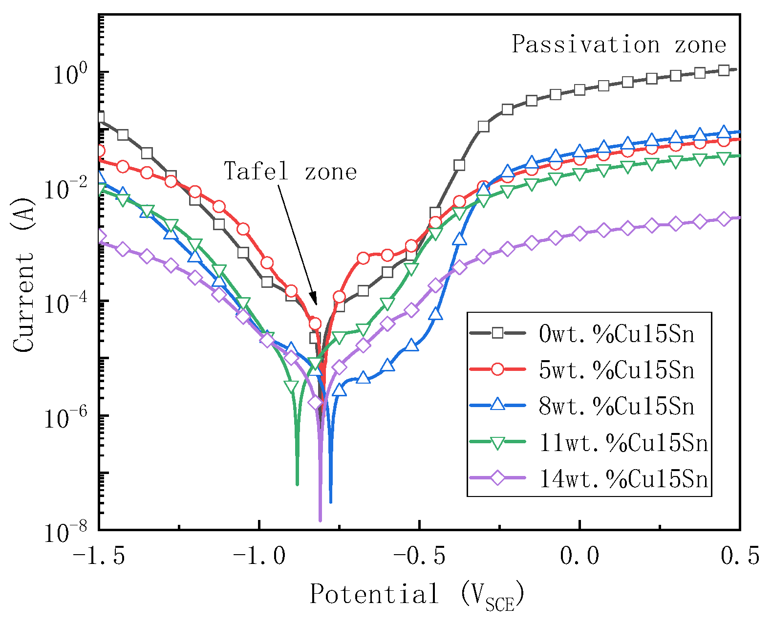
| Cu-Sn Addition Percent (wt.%) | Ecorr (VSCE) | Icorr (10−6A/cm2) |
|---|---|---|
| 0 | −0.81 | 78.53 |
| 5 | −0.80 | 38.16 |
| 8 | −0.78 | 11.43 |
| 11 | −0.88 | 5.16 |
| 14 | −0.81 | 4.30 |
| Alloy and State | Selected Area or Spots | Chemical Compisition (wt.%) | Phase | |||||
|---|---|---|---|---|---|---|---|---|
| Fe | Cu | Co | Sn | P | O | |||
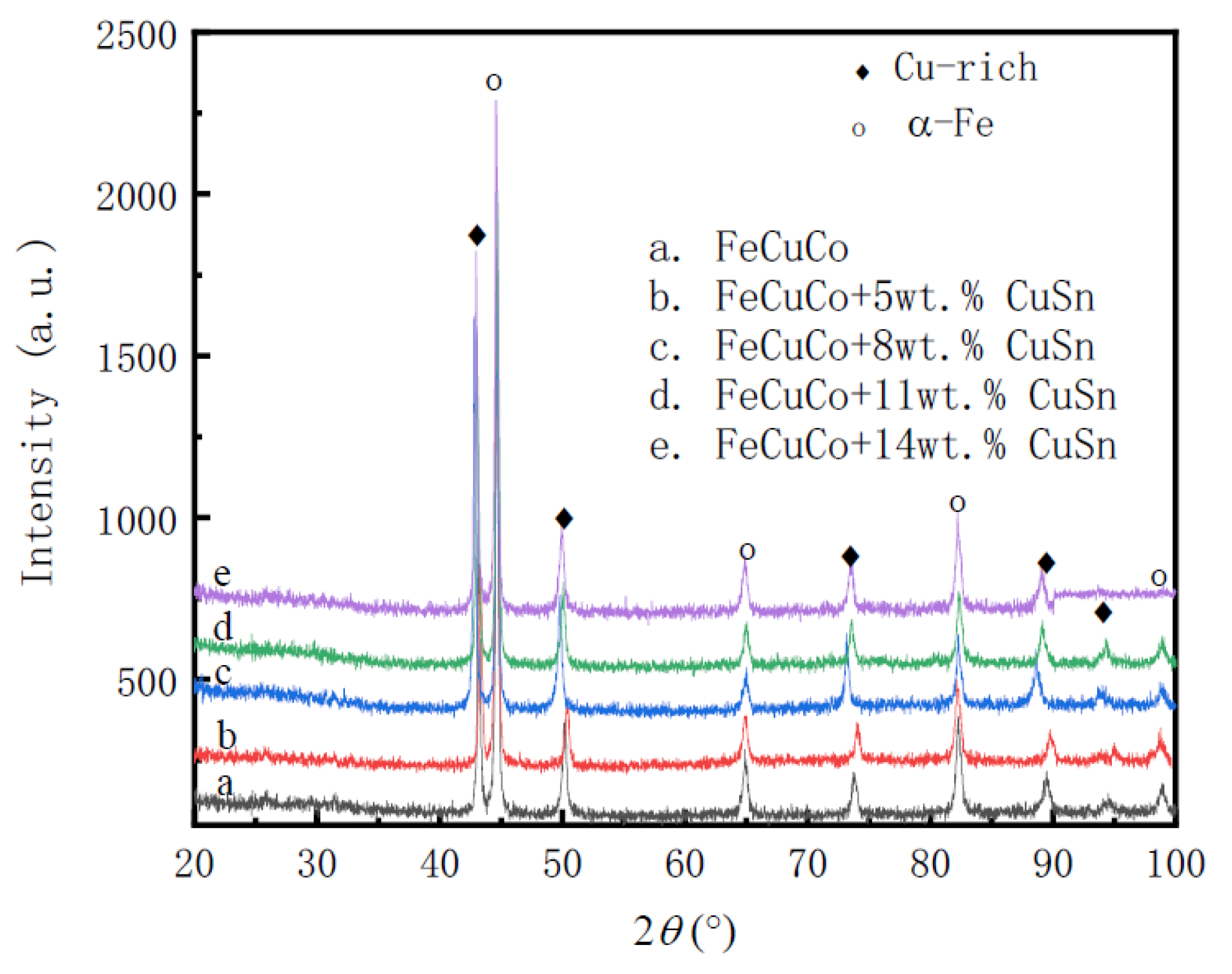
| Fe-Cu-Co alloy without Cu-Sn addition before electrochemical test, EDS area refer to Figure 6a | 1 | 7.04 | 89.94 | 3.01 | Cu-rich | |||
| 2 | 6.86 | 90.01 | 3.12 | Cu-rich | ||||
| 3 | 6.08 | 91.11 | 2.81 | Cu-rich | ||||
| 4 | 68.29 | 3.43 | 28.36 | α-Fe | ||||
| 5 | 68.31 | 4.01 | 27.68 | α-Fe | ||||
| 6 | 68.26 | 5.16 | 26.57 | α-Fe | ||||
| Fe-Cu-Co alloy without Cu-Sn addition after electrochemical test, EDS spots refer to Figure 6b | 1 | 3.96 | 92.57 | 1.88 | 0.34 | 1.25 | Cu-rich | |
| 4 | 4.41 | 92.03 | 1.44 | 0.47 | 1.66 | Cu-rich | ||
| 3 | 22.84 | 3.00 | 0.89 | 25.61 | 47.66 | α-Fe active corrosion products | ||
| 5 | 48.91 | 2.03 | 0.63 | 17.74 | 30.70 | α-Fe active corrosion products | ||
| 2 | 48.9 | 3.55 | 23.95 | 21.62 | 1.97 | α-Fe clean | ||
| 6 | 28.03 | 37.17 | 5.38 | 9.71 | 19.70 | Cu-rich + α-Fe active corrosion products | ||
| Fe-Cu-Co alloy with 11 wt.% Cu-Sn addition after electrochemical test, EDS spots refer to Figure 6c | 1 | 11.77 | 74.34 | 3.31 | 5.66 | 0.39 | 4.52 | Cu-rich passivation film |
| 2 | 32.70 | 44.73 | 8.41 | 4.19 | 1.81 | 8.17 | Cu-rich + α-Fe passivation film | |
| 4 | 50.80 | 32.10 | 11.25 | 0.79 | 0.42 | 4.63 | α-Fe + Cu-richpassivation film | |
| 3 | 72.35 | 4.92 | 16.04 | 0.96 | 0.59 | 5.14 | α-Fe passivation film | |
| 5 | 72.42 | 3.30 | 16.86 | 0.46 | 1.41 | 5.55 | α-Fe passivation film | |
| 6 | 69.33 | 6.79 | 16.74 | 0.46 | 0.22 | 6.46 | α-Fe passivation film | |
Disclaimer/Publisher’s Note: The statements, opinions and data contained in all publications are solely those of the individual author(s) and contributor(s) and not of MDPI and/or the editor(s). MDPI and/or the editor(s) disclaim responsibility for any injury to people or property resulting from any ideas, methods, instructions or products referred to in the content. |
© 2023 by the authors. Licensee MDPI, Basel, Switzerland. This article is an open access article distributed under the terms and conditions of the Creative Commons Attribution (CC BY) license (https://creativecommons.org/licenses/by/4.0/).
Share and Cite
Tao, H.; Ma, Y.; Chen, Y.; Du, S.; Zhou, H.; Yin, Y.; Li, Y.; Luo, F. Effect of Cu-Sn Addition on Corrosion Property of Pressureless Sintered Fe-Cu-Co Substrate Alloys. Materials 2023, 16, 728. https://doi.org/10.3390/ma16020728
Tao H, Ma Y, Chen Y, Du S, Zhou H, Yin Y, Li Y, Luo F. Effect of Cu-Sn Addition on Corrosion Property of Pressureless Sintered Fe-Cu-Co Substrate Alloys. Materials. 2023; 16(2):728. https://doi.org/10.3390/ma16020728
Chicago/Turabian StyleTao, Hongliang, Yunzhu Ma, Yuhui Chen, Shuai Du, Haojun Zhou, Yuhang Yin, Yimin Li, and Fenghua Luo. 2023. "Effect of Cu-Sn Addition on Corrosion Property of Pressureless Sintered Fe-Cu-Co Substrate Alloys" Materials 16, no. 2: 728. https://doi.org/10.3390/ma16020728