
A Review of Metamaterials in Wireless Power Transfer


Abstract
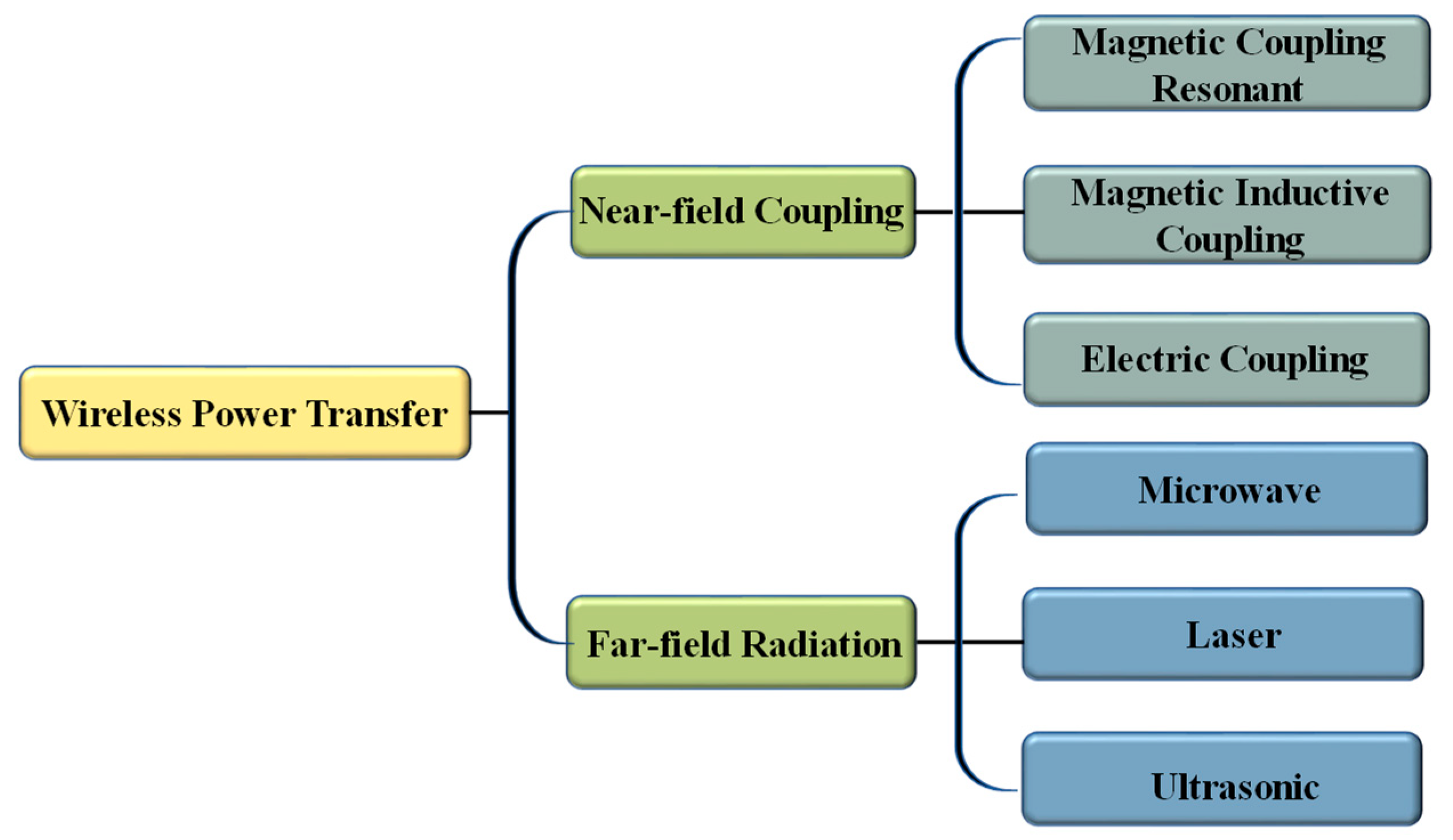
:1. Introduction
- Section 2 briefly introduces the basic principles of WPT technology.
- Section 3 describes the application principles of metamaterials in WPT from two perspectives, namely, electromagnetic modulation and the circuit theory.
- Section 4 introduces the current unit structures and design methods of metamaterials.
- Section 5 provides a comprehensive review of WPT technology based on metamaterials from three aspects: transmission efficiency, misalignment tolerance, and electromagnetic shielding.
- Section 6 discusses the limitations and prospects of metamaterials applied in WPT systems.
- Section 7 summarizes the entire article.
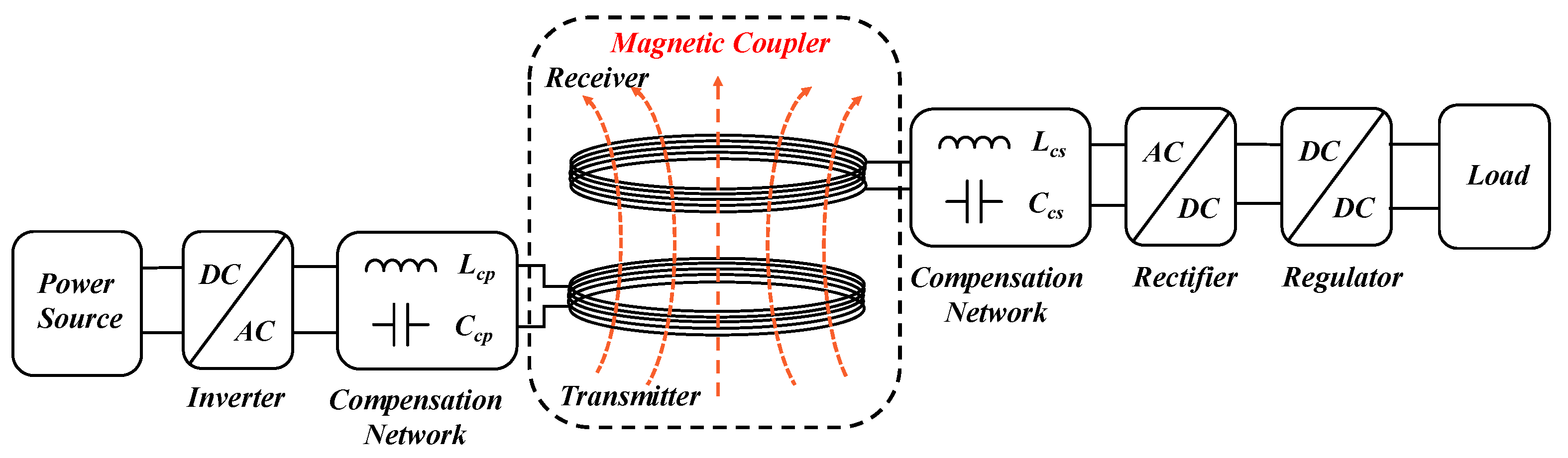
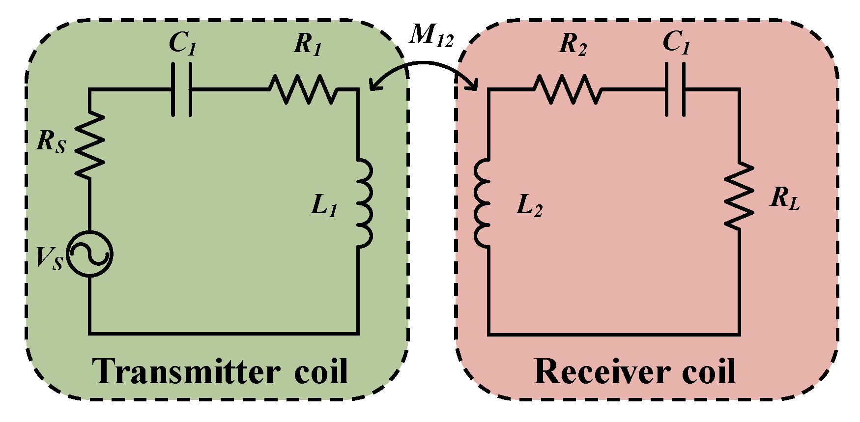
2. Analysis of MCR-WPT
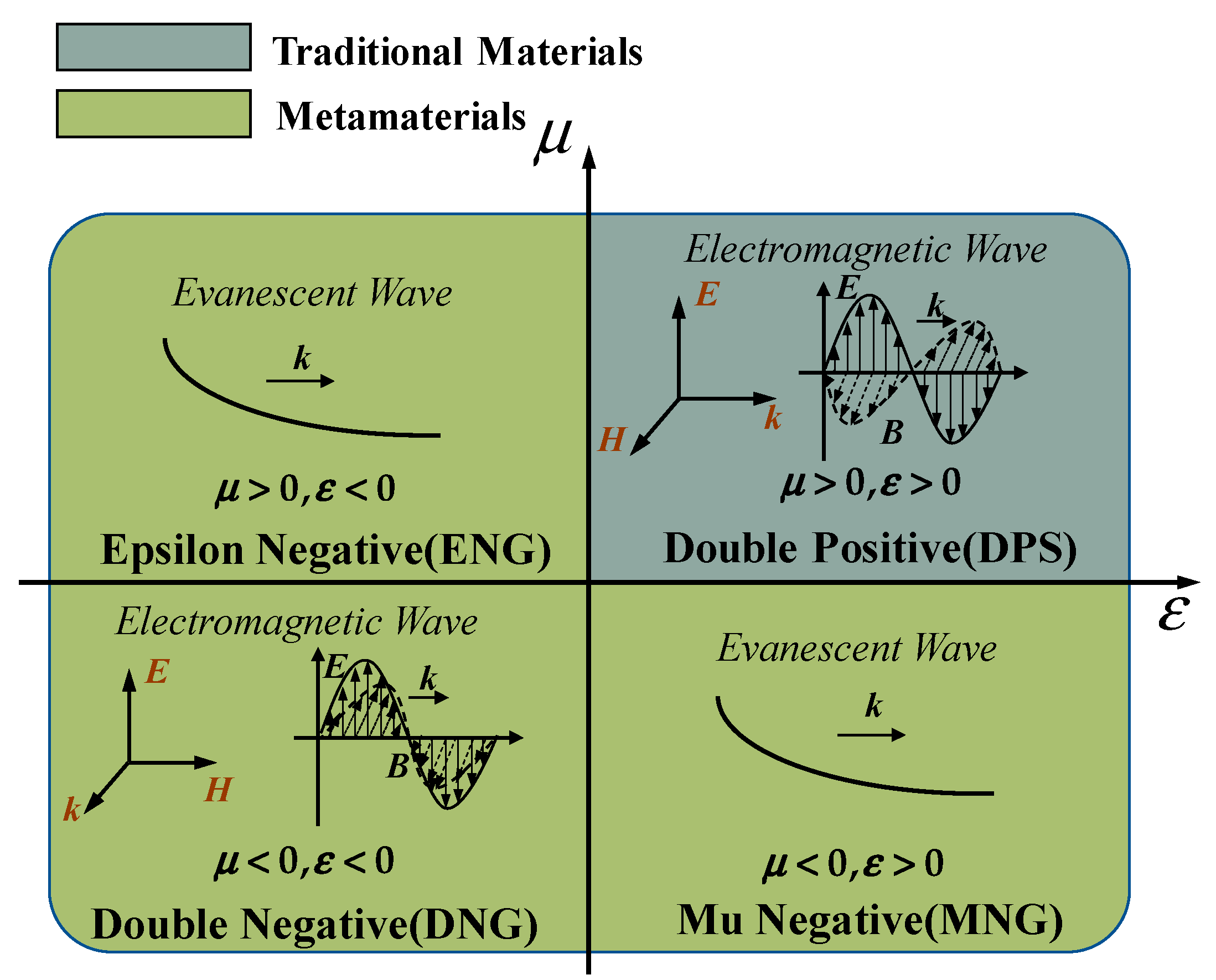
3. Fundamental of Metamaterials
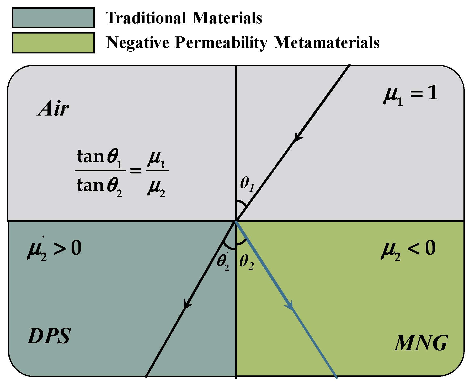
3.1. Negative Refractive Index
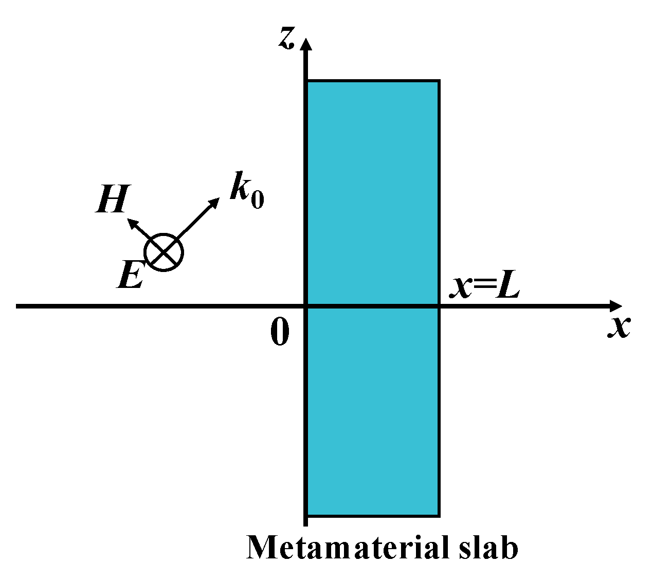
3.2. Evanescent Wave Amplification and Magnetic Shielding
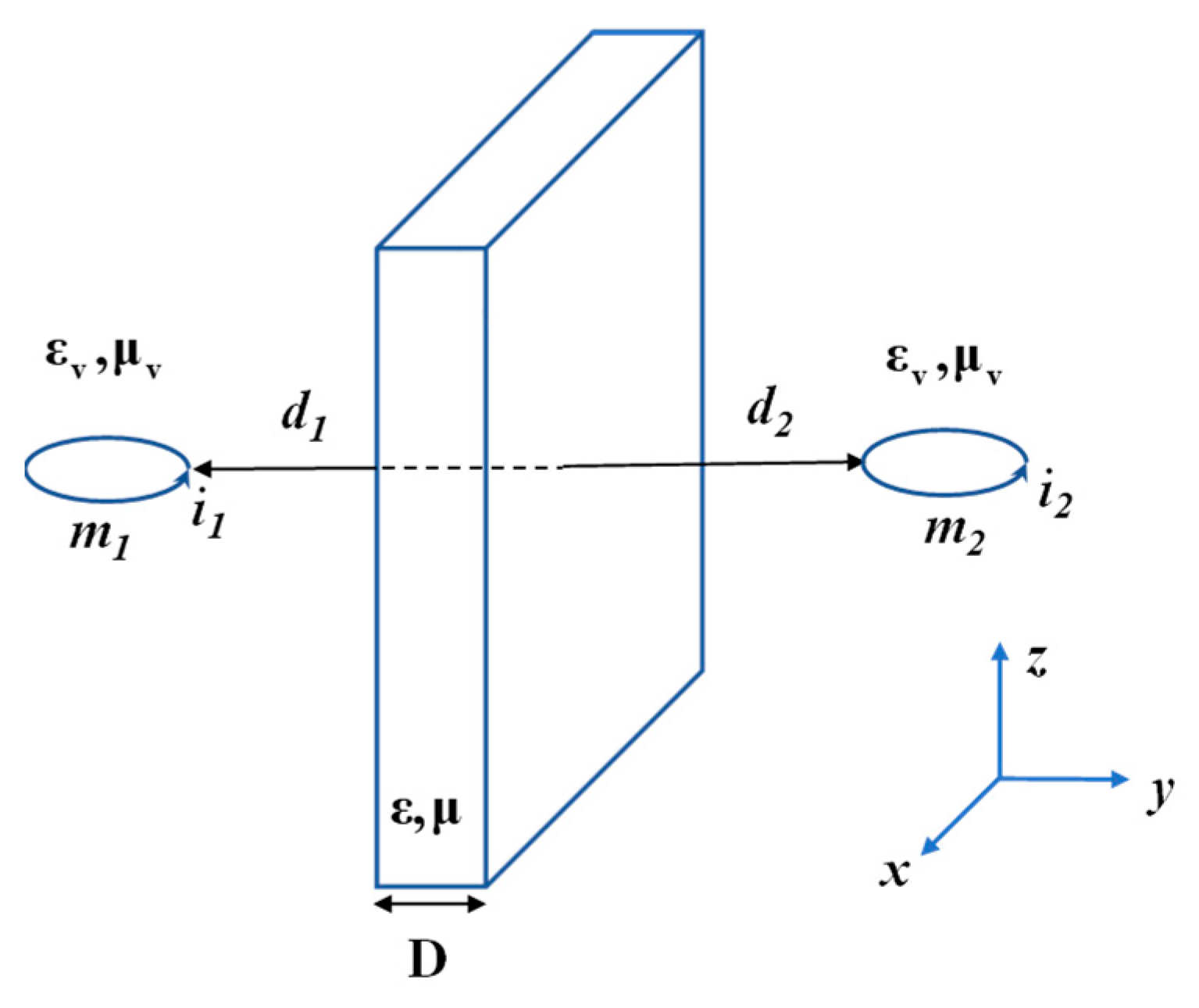
3.3. Magnetic Dipole Coupling Theory
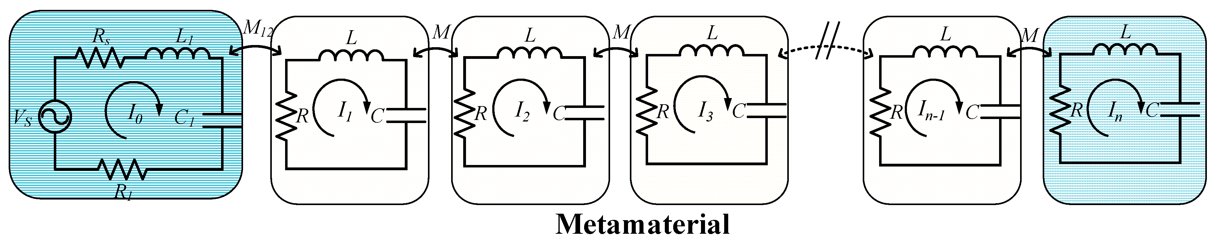
3.4. Magnetic Inductive Wave Theory
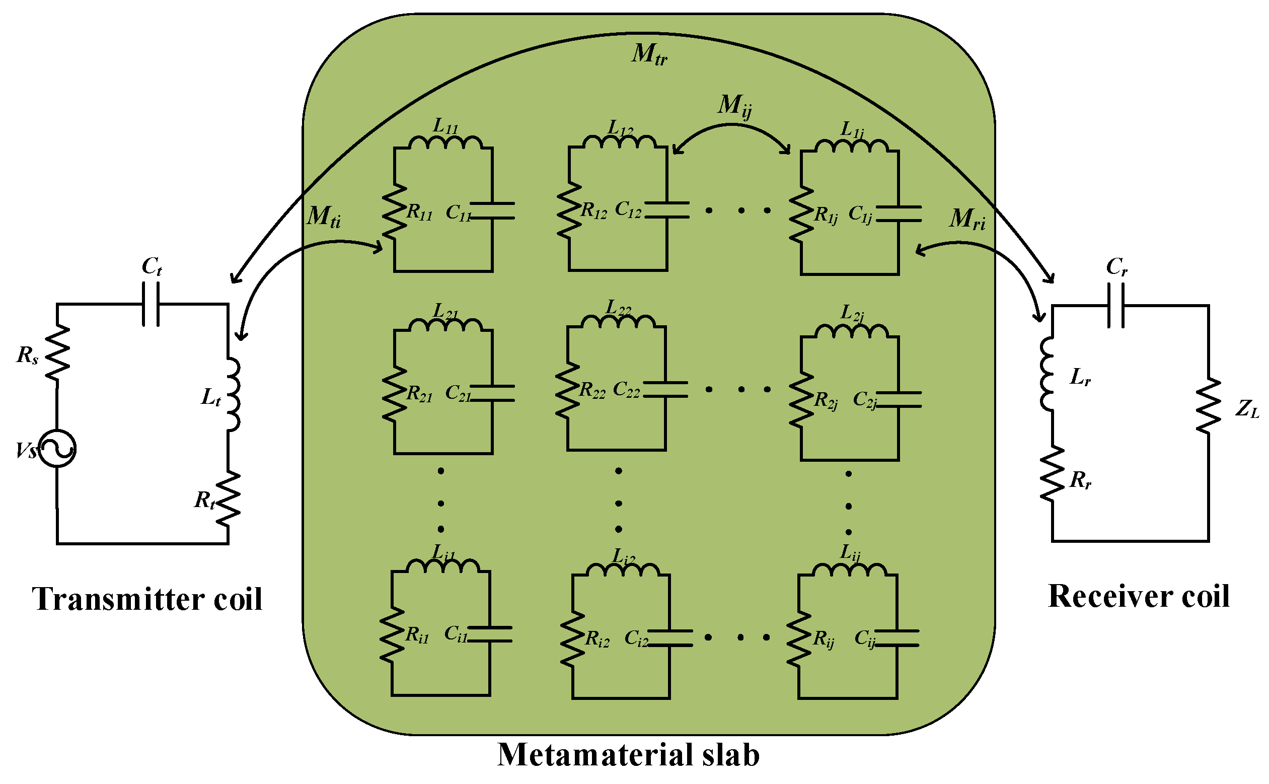
3.5. Equivalent Circuit Theory
4. Structure and Design of Metamaterials
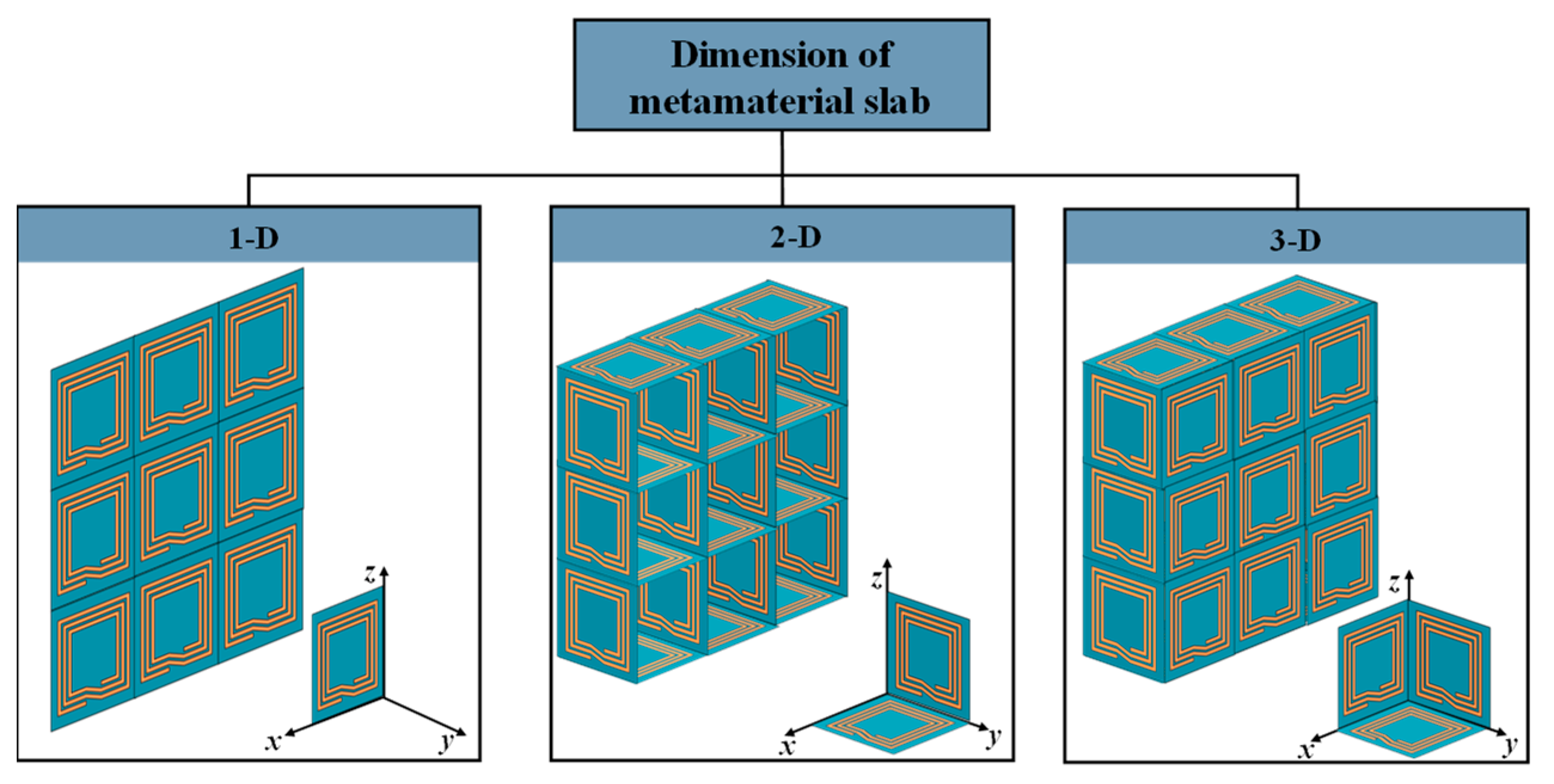
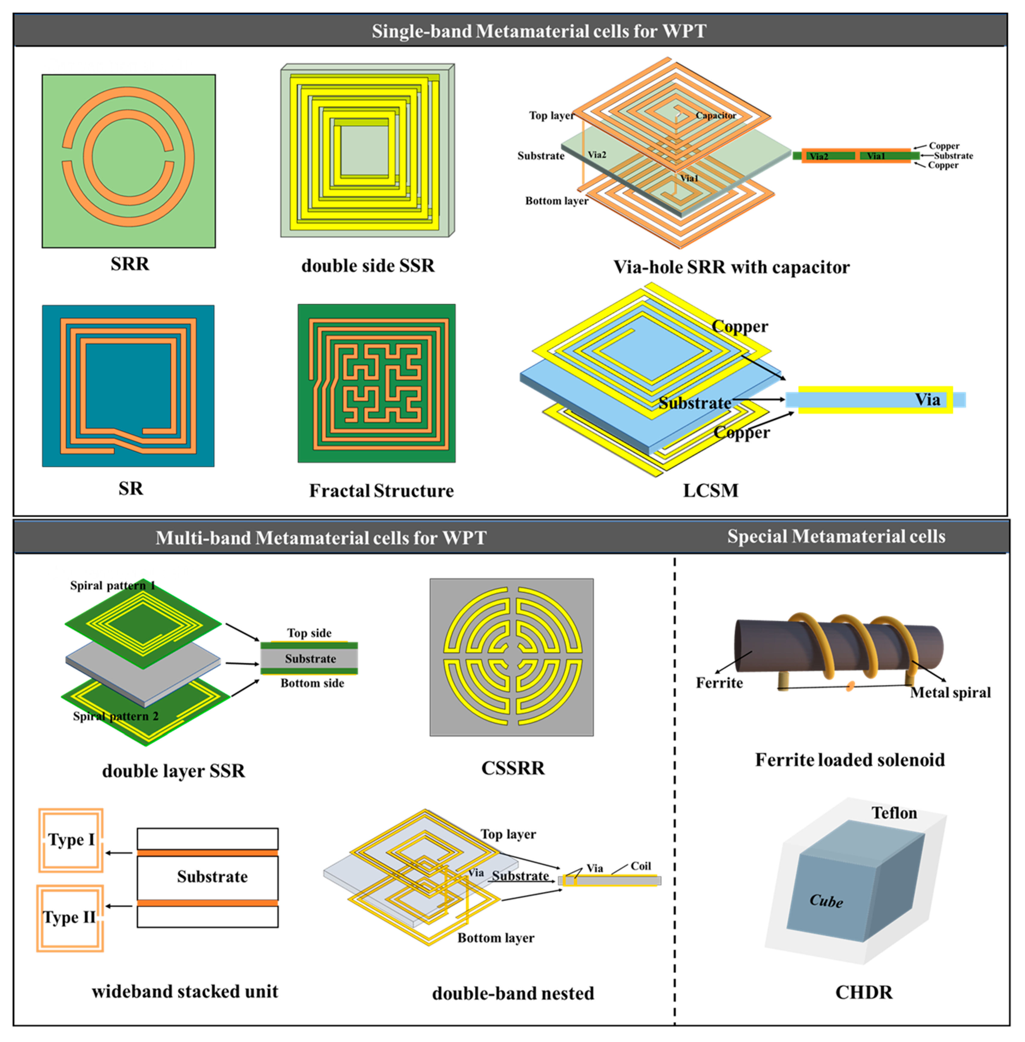
4.1. Structure of the Metamaterial

4.2. Design of the Metamaterial
4.2.1. S-parameter Inversion Method
4.2.2. Equivalent Model Method
5. WPT System Using Metamaterials
5.1. Efficiency and Distance Improvement
5.2. Misalignment
5.3. Improving Electromagnetic Leakage
6. Challenge and Prospect of Metamaterial in WPT Systems
- Design of miniaturized metamaterials for low-frequency applications. Currently, most low-frequency metamaterials operate in the MHz frequency range, which is too high for most electrical and electromagnetic devices. Moreover, the overall size of low-frequency metamaterials is large, which is not conducive to practical use in electromagnetic devices. The frequency range of electric vehicles and portable electronic devices is mostly in the kHz range. To enable metamaterials to meet the practical applications of WPT, it is necessary to study and design miniaturized metamaterials for low frequencies.
- Improve theoretical analysis. Existing simulation methods for microwave metamaterials are mostly based on the electromagnetic wave theory, but there is a lack of corresponding theoretical analysis for low-frequency metamaterials. Although low-frequency metamaterials have been designed using the equivalent circuit models, when the structure of metamaterials is complex, simple RLC resonant circuit models will be difficult to accurately describe their electromagnetic properties.
- Placement of metamaterials in WPT systems. Currently, most studies on metamaterial plates are placed between the receiving coil and the transmitting coil, which is very beneficial for improving the transmission efficiency of the system, but greatly reduces the practicality of metamaterials. The ideal placement position of metamaterials is fixed on the resonant coil, but when metamaterials are close to the transmitting coil, strong coupling between them will cause frequency splitting; when they are close to the receiving coil, the magnetic fields dissipate during the transmission process from the transmitting coil to the receiving coil, which cannot guarantee the transmission efficiency of the system. Therefore, it is necessary to study the placement position of metamaterial plates for practical applications.
- Design of multi-frequency and wideband metamaterials. Currently, most metamaterials adopt resonant metamaterials, which can only operate at fixed frequencies. In practical applications, compared to single-frequency metamaterials, dual-frequency or even multi-frequency metamaterials can improve the transmission efficiency and electromagnetic safety of two or more frequencies simultaneously. To further expand the application scenarios of metamaterials and achieve the simultaneous transmission of energy and signals, it is necessary to study wideband metamaterials with exotic electromagnetic properties.
- Achieve dynamic electromagnetic control. Passive metamaterials often come with certain energy losses, and their ability for electromagnetic control is relatively limited, which restricts their practical application in engineering. Research on intelligent control metamaterials can compensate for the energy losses of the elements and meet the different electromagnetic control requirements of WPT systems.
7. Conclusions
Funding
Institutional Review Board Statement
Informed Consent Statement
Data Availability Statement
Conflicts of Interest
References
- Tesla, N. Experiments with alternate currents of very high frequency and their application to methods of artificial illumination. Trans. Am. Inst. Electr. Eng. 1891, 8, 266–319. [Google Scholar] [CrossRef]
- Brown, W. Experiments in the transportation of energy by microwave beam. In Proceedings of the 1958 IRE International Convention Record, New York, NY, USA, 21–25 March 1966; pp. 8–17. [Google Scholar]
- Kurs, A.; Karalis, A.; Moffatt, R.; Joannopoulos, J.D.; Fisher, P.; Soljacic, M. Wireless power transfer via strongly coupled magnetic resonances. Science 2007, 317, 83–86. [Google Scholar] [CrossRef] [PubMed]
- Lazzeroni, P.; Cirimele, V.; Canova, A. Economic and environmental sustainability of Dynamic Wireless Power Transfer for electric vehicles supporting reduction of local air pollutant emissions. Renew. Sustain. Energy Rev. 2021, 138, 110537. [Google Scholar] [CrossRef]
- Qin, R.; Li, J.; Costinett, D. A 6.6-kW high-frequency wireless power transfer system for electric vehicle charging using multilayer nonuniform self-resonant coil at MHz. IEEE Trans. Power Electron. 2021, 37, 4842–4856. [Google Scholar] [CrossRef]
- Soares, L.; Wang, H. A study on renewed perspectives of electrified road for wireless power transfer of electric vehicles. Renew. Sustain. Energy Rev. 2022, 158, 112110. [Google Scholar] [CrossRef]
- Mohammad, M.; Onar, O.C.; Su, G.-J.; Pries, J.; Galigekere, V.P.; Anwar, S.; Asa, E.; Wilkins, J.; Wiles, R.; White, C.P. Bidirectional LCC–LCC-compensated 20-kW wireless power transfer system for medium-duty vehicle charging. IEEE Trans. Transp. Electrif. 2021, 7, 1205–1218. [Google Scholar] [CrossRef]
- Mohamed, N.; Aymen, F.; Alqarni, M.; Turky, R.A.; Alamri, B.; Ali, Z.M.; Aleem, S.H.A. A new wireless charging system for electric vehicles using two receiver coils. Ain Shams Eng. J. 2022, 13, 101569. [Google Scholar] [CrossRef]
- Rong, C.; He, X.; Wu, Y.; Qi, Y.; Wang, R.; Sun, Y.; Liu, M. Optimization design of resonance coils with high misalignment tolerance for drone wireless charging based on genetic algorithm. IEEE Trans. Ind. Appl. 2021, 58, 1242–1253. [Google Scholar] [CrossRef]
- Jawad, A.M.; Jawad, H.M.; Nordin, R.; Gharghan, S.K.; Abdullah, N.F.; Abu-Alshaeer, M.J. Wireless power transfer with magnetic resonator coupling and sleep/active strategy for a drone charging station in smart agriculture. IEEE Access 2019, 7, 139839–139851. [Google Scholar] [CrossRef]
- Rong, C.; He, X.; Zeng, Y.; Lu, C.; Liu, M. High-efficiency orientation insensitive WPT systems using magnetic dipole coil for low-power devices. IEEE Trans. Power Electron. 2021, 37, 4985–4990. [Google Scholar] [CrossRef]
- Ishihara, M.; Fujiki, K.; Umetani, K.; Hiraki, E. Autonomous system concept of multiple-receiver inductive coupling wireless power transfer for output power stabilization against cross-interference among receivers and resonance frequency tolerance. IEEE Trans. Ind. Appl. 2021, 57, 3898–3910. [Google Scholar] [CrossRef]
- Khan, S.R.; Pavuluri, S.K.; Cummins, G.; Desmulliez, M.P. Wireless power transfer techniques for implantable medical devices: A review. Sensors 2020, 20, 3487. [Google Scholar] [CrossRef]
- Campi, T.; Cruciani, S.; Maradei, F.; Montalto, A.; Musumeci, F.; Feliziani, M. Centralized high power supply system for implanted medical devices using wireless power transfer technology. IEEE Trans. Med. Robot. Bionics 2021, 3, 992–1001. [Google Scholar] [CrossRef]
- Pokharel, R.K.; Barakat, A.; Alshhawy, S.; Yoshitomi, K.; Sarris, C. Wireless power transfer system rigid to tissue characteristics using metamaterial inspired geometry for biomedical implant applications. Sci. Rep. 2021, 11, 5868. [Google Scholar] [CrossRef] [PubMed]
- Haerinia, M.; Shadid, R. Wireless power transfer approaches for medical implants: A review. Signals 2020, 1, 209–229. [Google Scholar] [CrossRef]
- Detka, K.; Górecki, K. Wireless power transfer—A review. Energies 2022, 15, 7236. [Google Scholar] [CrossRef]
- Mou, X.; Gladwin, D.T.; Zhao, R.; Sun, H. Survey on magnetic resonant coupling wireless power transfer technology for electric vehicle charging. IET Power Electron. 2019, 12, 3005–3020. [Google Scholar] [CrossRef]
- Yousuf, M.A.; Das, T.K.; Khallil, M.E.; Aziz, N.A.A.; Rana, M.J.; Hossain, S. Comparison study of inductive coupling and magnetic resonant coupling method for wireless power transmission of electric vehicles. In Proceedings of the 2021 2nd International Conference on Robotics, Electrical and Signal Processing Techniques (ICREST), Dhaka, Bangladesh, 5–7 January 2021; pp. 737–741. [Google Scholar]
- Rahman, M.; Rahman, F.; Rasheduzzaman, A.; Shahriyar, M.F.; Ali, M.T. Magnetic resonance coupled wireless power transfer analysis for electric vehicle. In Proceedings of the 2021 3rd Global Power, Energy and Communication Conference (GPECOM), Antalya, Turkey, 5–8 October 2021; pp. 28–33. [Google Scholar]
- Rehman, M.; Nallagownden, P.; Baharudin, Z. Efficiency investigation of SS and SP compensation topologies for wireless power transfer. Int. J. Power Electron. Drive Syst. 2019, 10, 2157. [Google Scholar] [CrossRef]
- Mosammam, B.M.; Mirsalim, M. New integrated tripolar pad using double-sided LCC compensation for wireless power transfer. IEEE Trans. Veh. Technol. 2020, 69, 15633–15643. [Google Scholar] [CrossRef]
- Yenil, V.; Cetin, S. An improved pulse density modulation control for secondary side controlled wireless power transfer system using LCC-S compensation. IEEE Trans. Ind. Electron. 2021, 69, 12762–12772. [Google Scholar] [CrossRef]
- Cheng, C.; Lu, F.; Zhou, Z.; Li, W.; Deng, Z.; Li, F.; Mi, C. A load-independent LCC-compensated wireless power transfer system for multiple loads with a compact coupler design. IEEE Trans. Ind. Electron. 2019, 67, 4507–4515. [Google Scholar] [CrossRef]
- Li, X.; Hu, J.; Wang, H.; Dai, X.; Sun, Y. A new coupling structure and position detection method for segmented control dynamic wireless power transfer systems. IEEE Trans. Power Electron. 2020, 35, 6741–6745. [Google Scholar] [CrossRef]
- Feng, T.; Sun, Y.; Feng, Y.; Dai, X. A tripolar plane-type transmitter for three-dimensional omnidirectional wireless power transfer. IEEE Trans. Ind. Appl. 2021, 58, 1254–1267. [Google Scholar] [CrossRef]
- Rong, C.; He, X.; Liu, M.; Wang, Y.; Liu, X.; Lu, C.; Zeng, Y.; Liu, R. Omnidirectional free-degree wireless power transfer system based on magnetic dipole coils for multiple receivers. IEEE Access 2021, 9, 81588–81600. [Google Scholar] [CrossRef]
- Kim, J.H.; Choi, B.G.; Jeong, S.Y.; Han, S.H.; Kim, H.R.; Rim, C.T.; Kim, Y.-S. Plane-type receiving coil with minimum number of coils for omnidirectional wireless power transfer. IEEE Trans. Power Electron. 2019, 35, 6165–6174. [Google Scholar] [CrossRef]
- Acero, J.; Lope, I.; Carretero, C.; Sarnago, H.; Burdío, J.M. Comparative Evaluation of Different Cables for Magnetic Couplers in Inductive Power Transfer Systems. In Proceedings of the 2023 IEEE Applied Power Electronics Conference and Exposition (APEC), Orlando, FL, USA, 19–23 March 2023; pp. 3302–3306. [Google Scholar]
- de Miranda, C.M.; Pichorim, S.F. A Three-Coil Wireless Power Transfer System using Self-Resonant Open-Bifilar Coils. AEU-Int. J. Electron. Commun. 2022, 154, 154300. [Google Scholar] [CrossRef]
- Dong, Z.; Liu, S.; Li, X.; Xu, Z.; Yang, L. A novel long-distance wireless power transfer system with constant current output based on domino-resonator. IEEE J. Emerg. Sel. Top. Power Electron. 2020, 9, 2343–2355. [Google Scholar] [CrossRef]
- International Commission on Non-Ionizing Radiation Protection (ICNIRP). Guidelines for limiting exposure to electromagnetic fields (100 kHz to 300 GHz). Health Phys. 2020, 118, 483–524. [Google Scholar]
- Kwan, C.H.; Arteaga, J.M.; Pucci, N.; Yates, D.C.; Mitcheson, P.D. A 110w e-scooter wireless charger operating at 6.78 mhz with ferrite shielding. In Proceedings of the 2021 IEEE PELS Workshop on Emerging Technologies: Wireless Power Transfer (WoW), San Diego, CA, USA, 1–4 June 2021; pp. 1–4. [Google Scholar]
- Haga, N.; Chakarothai, J.; Konno, K. Circuit modeling of a wireless power transfer system containing ferrite shields using an extended impedance expansion method. IEEE Trans. Microw. Theory Tech. 2022, 70, 2872–2881. [Google Scholar] [CrossRef]
- Ahire, D.; Gond, V.J.; Chopade, J.J. Coil material and magnetic shielding methods for efficient wireless power transfer system for biomedical implant application. Biosens. Bioelectron. X 2022, 10, 100123. [Google Scholar] [CrossRef]
- Huangfu, J.; Ran, L.; Chen, H.; Zhang, X.-M.; Chen, K.; Grzegorczyk, T.M.; Kong, J.A. Experimental confirmation of negative refractive index of a metamaterial composed of Ω-like metallic patterns. Appl. Phys. Lett. 2004, 84, 1537–1539. [Google Scholar] [CrossRef]
- Seddon, N.; Bearpark, T. Observation of the inverse Doppler effect. Science 2003, 302, 1537–1540. [Google Scholar] [CrossRef] [PubMed]
- Pendry, J.B. Negative refraction makes a perfect lens. Phys. Rev. Lett. 2000, 85, 3966. [Google Scholar] [CrossRef]
- Veselago, V.G. Electrodynamics of substances with simultaneously negative and. Usp. Fiz. Nauk 1967, 92, 517. [Google Scholar] [CrossRef]
- Pendry, J.B.; Holden, A.; Stewart, W.; Youngs, I. Extremely low frequency plasmons in metallic mesostructures. Phys. Rev. Lett. 1996, 76, 4773. [Google Scholar] [CrossRef] [PubMed]
- Pendry, J.B.; Holden, A.; Robbins, D.; Stewart, W. Low frequency plasmons in thin-wire structures. J. Phys. Condens. Matter 1998, 10, 4785. [Google Scholar] [CrossRef]
- Pendry, J.B.; Holden, A.J.; Robbins, D.J.; Stewart, W. Magnetism from conductors and enhanced nonlinear phenomena. IEEE Trans. Microw. Theory Tech. 1999, 47, 2075–2084. [Google Scholar] [CrossRef]
- Shelby, R.A.; Smith, D.R.; Schultz, S. Experimental verification of a negative index of refraction. Science 2001, 292, 77–79. [Google Scholar] [CrossRef]
- Wang, B.; Nishino, T.; Teo, K.H. Wireless power transmission efficiency enhancement with metamaterials. In Proceedings of the 2010 IEEE International Conference on Wireless Information Technology and Systems, Honolulu, HI, USA, 28 August–3 September 2010; pp. 1–4. [Google Scholar]
- Wang, B.; Teo, K.H.; Nishino, T.; Yerazunis, W.; Barnwell, J.; Zhang, J. Experiments on wireless power transfer with metamaterials. Appl. Phys. Lett. 2011, 98, 254101. [Google Scholar] [CrossRef]
- Shan, D.; Wang, H.; Cao, K.; Zhang, J. Wireless power transfer system with enhanced efficiency by using frequency reconfigurable metamaterial. Sci. Rep. 2022, 12, 331. [Google Scholar] [CrossRef]
- Adepoju, W.; Bhattacharya, I.; Sanyaolu, M.; Esfahani, E.N. Equivalent circuit modeling and experimental analysis of low frequency metamaterial for efficient wireless power transfer. IEEE Access 2022, 10, 87962–87973. [Google Scholar] [CrossRef]
- Lee, W.; Yoon, Y.-K. Tunable metamaterial slab for efficiency improvement in misaligned wireless power transfer. IEEE Microw. Wirel. Compon. Lett. 2020, 30, 912–915. [Google Scholar] [CrossRef]
- Jiang, X.; Pokharel, R.K.; Barakat, A.; Yoshitomi, K. A multimode metamaterial for a compact and robust dualband wireless power transfer system. Sci. Rep. 2021, 11, 22125. [Google Scholar] [CrossRef] [PubMed]
- Lu, C.; Huang, X.; Rong, C.; Tao, X.; Zeng, Y.; Liu, M. A dual-band negative permeability and near-zero permeability metamaterials for wireless power transfer system. IEEE Trans. Ind. Electron. 2020, 68, 7072–7082. [Google Scholar] [CrossRef]
- Besnoff, J.; Chabalko, M.; Ricketts, D.S. A frequency-selective zero-permeability metamaterial shield for reduction of near-field electromagnetic energy. IEEE Antennas Wirel. Propag. Lett. 2015, 15, 654–657. [Google Scholar] [CrossRef]
- Rong, C.; Wang, Y.; Chen, M.; Lu, Y.; Wu, Z.; Xia, C.; Liao, Z.; Liu, X. A Comprehensive Analysis of Metamaterial-Coupled WPT Systems for Low Electromagnetic Field Leakage. IEEE Trans. Electromagn. Compat. 2022, 65, 166–176. [Google Scholar] [CrossRef]
- Jeong, S.; Kim, D.-H.; Song, J.; Kim, H.; Lee, S.; Song, C.; Lee, J.; Song, J.; Kim, J. Smartwatch strap wireless power transfer system with flexible PCB coil and shielding material. IEEE Trans. Ind. Electron. 2018, 66, 4054–4064. [Google Scholar] [CrossRef]
- Jayalath, S.; Khan, A. Design, challenges, and trends of inductive power transfer couplers for electric vehicles: A review. IEEE J. Emerg. Sel. Top. Power Electron. 2020, 9, 6196–6218. [Google Scholar] [CrossRef]
- Behnamfar, M.; Javadi, H.; Afjei, E. A dynamic CPT system LC Compensated with a six-plate capacitive coupler for wireless charging of electric vehicle in motion. In Proceedings of the 2020 28th Iranian Conference on Electrical Engineering (ICEE), Tabriz, Iran, 4–6 August 2020; pp. 1–6. [Google Scholar]
- Shinohara, N. History and innovation of wireless power transfer via microwaves. IEEE J. Microw. 2021, 1, 218–228. [Google Scholar] [CrossRef]
- Mohammadnia, A.; Ziapour, B.M.; Ghaebi, H.; Khooban, M.H. Feasibility assessment of next-generation drones powering by laser-based wireless power transfer. Opt. Laser Technol. 2021, 143, 107283. [Google Scholar] [CrossRef]
- Guida, R.; Demirors, E.; Dave, N.; Melodia, T. Underwater ultrasonic wireless power transfer: A battery-less platform for the internet of underwater things. IEEE Trans. Mob. Comput. 2020, 21, 1861–1873. [Google Scholar] [CrossRef]
- Huang, X.; Lu, C.; Liu, M. Calculation and analysis of near-field magnetic spiral metamaterials for MCR-WPT application. Appl. Phys. A 2020, 126, 1–9. [Google Scholar] [CrossRef]
- Luo, Z.; Nie, S.; Pathmanathan, M.; Lehn, P.W. Exciter–Quadrature–Repeater transmitter for wireless electric vehicle charging with high lateral misalignment tolerance and low EMF emission. IEEE Trans. Transp. Electrif. 2021, 7, 2156–2167. [Google Scholar] [CrossRef]
- Kim, J.; Son, H.-C.; Kim, D.-H.; Park, Y.-J. Optimal design of a wireless power transfer system with multiple self-resonators for an LED TV. IEEE Trans. Consum. Electron. 2012, 58, 775–780. [Google Scholar] [CrossRef]
- Zanganeh, E.; Song, M.; Valero, A.C.; Shalin, A.S.; Nenasheva, E.; Miroshnichenko, A.; Evlyukhin, A.; Kapitanova, P. Nonradiating sources for efficient wireless power transfer. Nanophotonics 2021, 10, 4399–4408. [Google Scholar] [CrossRef]
- Wang, S.; Gao, D. Power transfer efficiency analysis of the 4-coil wireless power transfer system based on circuit theory and coupled-mode theory. In Proceedings of the 2016 IEEE 11th Conference on Industrial Electronics and Applications (ICIEA), Hefei, China, 5–7 June 2016; pp. 1230–1234. [Google Scholar]
- Cheon, S.; Kim, Y.-H.; Kang, S.-Y.; Lee, M.L.; Lee, J.-M.; Zyung, T. Circuit-model-based analysis of a wireless energy-transfer system via coupled magnetic resonances. IEEE Trans. Ind. Electron. 2010, 58, 2906–2914. [Google Scholar] [CrossRef]
- Duong, T.P.; Lee, J.-W. Experimental results of high-efficiency resonant coupling wireless power transfer using a variable coupling method. IEEE Microw. Wirel. Compon. Lett. 2011, 21, 442–444. [Google Scholar] [CrossRef]
- Shelby, R.A. Microwave Experiments with Left-Handed Materials; University of California: San Diego, CA, USA, 2001. [Google Scholar]
- Zhao, Y. Evanescent wave amplification and subwavelength imaging by ultrathin uniaxial μ-near-zero material. AIP Adv. 2014, 4, 27115. [Google Scholar] [CrossRef]
- Moorey, C.L.; Holderbaum, W.; Potter, B. Radiative power transmission from dipolar sources. In Proceedings of the 2013 IEEE Wireless Power Transfer (WPT), Perugia, Italy, 15–16 May 2013; pp. 206–209. [Google Scholar]
- Urzhumov, Y.; Smith, D.R. Metamaterial-enhanced coupling between magnetic dipoles for efficient wireless power transfer. Phys. Rev. B 2011, 83, 205114. [Google Scholar] [CrossRef]
- Younesiraad, H.; Bemani, M. Analysis of coupling between magnetic dipoles enhanced by metasurfaces for wireless power transfer efficiency improvement. Sci. Rep. 2018, 8, 14865. [Google Scholar] [CrossRef]
- Stevens, C.J.; Chan, C.W.; Stamatis, K.; Edwards, D.J. Magnetic metamaterials as 1-D data transfer channels: An application for magneto-inductive waves. IEEE Trans. Microw. Theory Tech. 2010, 58, 1248–1256. [Google Scholar] [CrossRef]
- Sandoval, F.S.; Delgado, S.M.T.; Moazenzadeh, A.; Wallrabe, U. A 2-D magnetoinductive wave device for freer wireless power transfer. IEEE Trans. Power Electron. 2019, 34, 10433–10445. [Google Scholar] [CrossRef]
- Sandoval, F.S.; Delgado, S.M.T.; Moazenzadeh, A.; Wallrabe, U. Nulls-free wireless power transfer with straightforward control of magnetoinductive waves. IEEE Trans. Microw. Theory Tech. 2017, 65, 1087–1093. [Google Scholar] [CrossRef]
- Ranaweera, A.; Pham, T.S.; Bui, H.N.; Ngo, V.; Lee, J.-W. An active metasurface for field-localizing wireless power transfer using dynamically reconfigurable cavities. Sci. Rep. 2019, 9, 11735. [Google Scholar] [CrossRef]
- Rakluea, C.; Worapishet, A.; Chaimool, S.; Zhao, Y.; Akkaraekthalin, P. True nulls-free magnetoinductive waveguides using alternate coupling polarities for batteryless dynamic wireless power transfer applications. IEEE Trans. Power Electron. 2022, 37, 8835–8854. [Google Scholar] [CrossRef]
- Chan, C.W.; Stevensy, C.J. Two-dimensional magneto-inductive wave data structures. In Proceedings of the 5th European Conference on Antennas and Propagation (EUCAP), Rome, Italy, 11–15 April 2011; pp. 1071–1075. [Google Scholar]
- Pham, T.S.; Bui, H.N.; Lee, J.-W. Wave propagation control and switching for wireless power transfer using tunable 2-D magnetic metamaterials. J. Magn. Magn. Mater. 2019, 485, 126–135. [Google Scholar] [CrossRef]
- Choi, J.; Seo, C.H. High-efficiency wireless energy transmission using magnetic resonance based on negative refractive index metamaterial. Prog. Electromagn. Res. 2010, 106, 33–47. [Google Scholar] [CrossRef]
- Chen, J.; Tan, H. Investigation of wireless power transfer with 3D metamaterial for efficiency enhancement. In Proceedings of the 2017 7th IEEE International Symposium on Microwave, Antenna, Propagation, and EMC Technologies (MAPE), Xi’an, China, 24–27 October 2017; pp. 309–312. [Google Scholar]
- Lipworth, G.; Ensworth, J.; Seetharam, K.; Huang, D.; Lee, J.S.; Schmalenberg, P.; Nomura, T.; Reynolds, M.S.; Smith, D.R.; Urzhumov, Y. Magnetic metamaterial superlens for increased range wireless power transfer. Sci. Rep. 2014, 4, 1–6. [Google Scholar] [CrossRef]
- Ranaweera, A.; Duong, T.P.; Lee, B.-S.; Lee, J.-W. Experimental investigation of 3D metamaterial for mid-range wireless power transfer. In Proceedings of the 2014 IEEE Wireless Power Transfer Conference, Jeju, Republic of Korea, 8–9 May 2014; pp. 92–95. [Google Scholar]
- Chabalko, M.J.; Besnoff, J.; Ricketts, D.S. Magnetic field enhancement in wireless power with metamaterials and magnetic resonant couplers. IEEE Antennas Wirel. Propag. Lett. 2015, 15, 452–455. [Google Scholar] [CrossRef]
- Li, W.; Wang, P.; Yao, C.; Zhang, Y.; Tang, H. Experimental investigation of 1D, 2D, and 3D metamaterials for efficiency enhancement in a 6.78 MHz wireless power transfer system. In Proceedings of the 2016 IEEE Wireless Power Transfer Conference (WPTC), Aveiro, Portugal, 5–6 May 2016; pp. 1–4. [Google Scholar]
- Rong, C.; Lu, C.; Zeng, Y.; Tao, X.; Liu, X.; Liu, R.; He, X.; Liu, M. A critical review of metamaterial in wireless power transfer system. IET Power Electron. 2021, 14, 1541–1559. [Google Scholar] [CrossRef]
- Kim, G.; Lee, B. Effects of metamaterial slab with negative permeability applied to magnetically-coupled wireless power transfer system. In Proceedings of the 2015 IEEE International Symposium on Antennas and Propagation & USNC/URSI National Radio Science Meeting, Vancouver, BC, Canada, 19–24 July 2015; pp. 113–114. [Google Scholar]
- Dong, Y.; Li, W.; Cai, W.; Yao, C.; Ma, D.; Tang, H. Experimental investigation of 6.78 MHz metamaterials for efficiency enhancement of wireless power transfer system. In Proceedings of the 2016 IEEE 2nd Annual Southern Power Electronics Conference (SPEC), Auckland, New Zealand, 5–8 December 2016; pp. 1–5. [Google Scholar]
- Chen, J.-F.; Ding, Z.; Hu, Z.; Wang, S.; Cheng, Y.; Liu, M.; Wei, B.; Wang, S. Metamaterial-based high-efficiency wireless power transfer system at 13.56 MHz for low power applications. Prog. Electromagn. Res. B 2017, 72, 17–30. [Google Scholar] [CrossRef]
- Chen, W.-C.; Bingham, C.M.; Mak, K.M.; Caira, N.W.; Padilla, W.J. Extremely subwavelength planar magnetic metamaterials. Phys. Rev. B 2012, 85, 201104. [Google Scholar] [CrossRef]
- Li, L.; Liu, H.; Zhang, H.; Xue, W. Efficient wireless power transfer system integrating with metasurface for biological applications. IEEE Trans. Ind. Electron. 2017, 65, 3230–3239. [Google Scholar] [CrossRef]
- Cho, Y.; Kim, J.J.; Kim, D.-H.; Lee, S.; Kim, H.; Song, C.; Kong, S.; Kim, H.; Seo, C.; Ahn, S. Thin PCB-type metamaterials for improved efficiency and reduced EMF leakage in wireless power transfer systems. IEEE Trans. Microw. Theory Tech. 2016, 64, 353–364. [Google Scholar] [CrossRef]
- Zhao, C.; Zhu, S.; Zhu, H.; Huang, Z.; Luo, X. Accurate design of deep sub-wavelength metamaterials for wireless power transfer enhancement. Prog. Electromagn. Res. C 2018, 83, 195–203. [Google Scholar] [CrossRef]
- Miyamaru, F.; Kubota, S.; Takeda, M.W. Terahertz response of split-ring resonators with fractal structures. Appl. Phys. Express 2012, 5, 72001. [Google Scholar] [CrossRef]
- Fan, X.; Tang, F.; Su, B.; Zhang, X. Design of spiral resonator based on fractal metamaterials and its improvement for MCR-WPT performance. IEEE Trans. Magn. 2022, 58, 1–9. [Google Scholar] [CrossRef]
- Gong, Z.; Yang, S. One-dimensional stacking miniaturized low-frequency metamaterial bulk for near-field applications. J. Appl. Phys. 2020, 127, 114901. [Google Scholar] [CrossRef]
- Lu, C.; Huang, X.; Liu, X.; Zeng, Y.; Liu, R.; Rong, C.; Liu, M. Design and optimization of the low-frequency metasurface shield for wireless power transfer system. IEEE Trans. Transp. Electrif. 2021, 8, 723–733. [Google Scholar] [CrossRef]
- Jiang, X.; Pokharel, R.K.; Barakat, A.; Yoshitomi, K. Wideband Stacked Metamaterial for a Compact and Efficient Dual-band Wireless Power Transfer. In Proceedings of the 2022 IEEE/MTT-S International Microwave Symposium-IMS 2022, Denver, CO, USA, 19–24 June 2022; pp. 198–201. [Google Scholar]
- Zheng, Z.; Fang, X.; Zheng, Y.; Feng, H. A wireless power transfer system based on dual-band metamaterials. IEEE Microw. Wirel. Compon. Lett. 2022, 32, 615–618. [Google Scholar] [CrossRef]
- Shaw, T.; Mitra, D. Design of miniaturized, low-loss and flexible multi-band metamaterial for microwave application. Appl. Phys. A 2018, 124, 1–11. [Google Scholar] [CrossRef]
- Das, R.; Basir, A.; Yoo, H. A metamaterial-coupled wireless power transfer system based on cubic high-dielectric resonators. IEEE Trans. Ind. Electron. 2018, 66, 7397–7406. [Google Scholar] [CrossRef]
- Shaw, T.; Mitra, D. Wireless power transfer system based on magnetic dipole coupling with high permittivity metamaterials. IEEE Antennas Wirel. Propag. Lett. 2019, 18, 1823–1827. [Google Scholar] [CrossRef]
- Rodríguez, E.S.G.; RamRakhyani, A.K.; Schurig, D.; Lazzi, G. Compact low-frequency metamaterial design for wireless power transfer efficiency enhancement. IEEE Trans. Microw. Theory Tech. 2016, 64, 1644–1654. [Google Scholar] [CrossRef]
- Adepoju, W.O.; Bhattacharya, I.; Bima, M.E.; Banik, T. Novel metamaterial and ai-based multi-objective optimization of coil parameters for efficient wireless power transfer. In Proceedings of the 2021 IEEE Vehicle Power and Propulsion Conference (VPPC), Gijon, Spain, 25–28 October 2021; pp. 1–6. [Google Scholar]
- Smith, D.; Vier, D.; Koschny, T.; Soukoulis, C. Electromagnetic parameter retrieval from inhomogeneous metamaterials. Phys. Rev. E 2005, 71, 36617. [Google Scholar] [CrossRef] [PubMed]
- Arslanagić, S.; Hansen, T.V.; Mortensen, N.A.; Gregersen, A.H.; Sigmund, O.; Ziolkowski, R.W.; Breinbjerg, O. A review of the scattering-parameter extraction method with clarification of ambiguity issues in relation to metamaterial homogenization. IEEE Antennas Propag. Mag. 2013, 55, 91–106. [Google Scholar] [CrossRef]
- Szabo, Z.; Park, G.-H.; Hedge, R.; Li, E.-P. A unique extraction of metamaterial parameters based on Kramers–Kronig relationship. IEEE Trans. Microw. Theory Tech. 2010, 58, 2646–2653. [Google Scholar] [CrossRef]
- Sydoruk, O.; Tatartschuk, E.; Shamonina, E.; Solymar, L. Analytical formulation for the resonant frequency of split rings. J. Appl. Phys. 2009, 105, 14903. [Google Scholar] [CrossRef]
- Soares, I.V.; Freitas, F.M.; Gonçalves, S.T.; Resende, Ú.C. Integro-Differential Analysis of Resonant Magnetic Metasurfaces With Equivalent Medium Approximation. IEEE Trans. Magn. 2023, 59, 5. [Google Scholar] [CrossRef]
- Usai, P.; Brizi, D.; Monorchio, A. Low Frequency Magnetic Metasurface for Wireless Power Transfer Applications: Reducing Losses Effect and Optimizing Loading Condition. IEEE Access 2023, 11, 66579–66586. [Google Scholar] [CrossRef]
- Lee, W.; Yoon, Y.-K. High efficiency metamaterial-based multi-scale wireless power transfer for smart home applications. In Proceedings of the 2021 IEEE MTT-S International Microwave Symposium (IMS), Atlanta, GA, USA, 7–25 June 2021; pp. 62–65. [Google Scholar]
- Cho, Y.; Lee, S.; Kim, D.-H.; Kim, H.; Song, C.; Kong, S.; Park, J.; Seo, C.; Kim, J. Thin hybrid metamaterial slab with negative and zero permeability for high efficiency and low electromagnetic field in wireless power transfer systems. IEEE Trans. Electromagn. Compat. 2017, 60, 1001–1009. [Google Scholar] [CrossRef]
- Lee, S.; Cho, Y.; Jeong, S.; Hong, S.; Sim, B.; Kim, H.; Kim, J. High efficiency wireless power transfer system using a two-stack hybrid metamaterial slab. In Proceedings of the 2019 IEEE Wireless Power Transfer Conference (WPTC), London, UK, 18–21 June 2019; pp. 616–619. [Google Scholar]
- Yang, W.; Ho, S.-L.; Fu, W. Numerical and experimental study on design optimization of hybrid metamaterial slab for wireless power transmission. IEEE Access 2020, 8, 82700–82708. [Google Scholar] [CrossRef]
- Brizi, D.; Stang, J.P.; Monorchio, A.; Lazzi, G. A compact magnetically dispersive surface for low-frequency wireless power transfer applications. IEEE Trans. Antennas Propag. 2020, 68, 1887–1895. [Google Scholar] [CrossRef]
- Zhu, S.; Zhao, C.; Huang, Z.; Zhang, Y.; Luo, X. Enhancement of wireless power transmission based on side-positioned metamaterials. In Proceedings of the 2018 IEEE PES Asia-Pacific Power and Energy Engineering Conference (APPEEC), Kota Kinabalu, Malaysia, 7–10 October 2018; pp. 241–245. [Google Scholar]
- Lu, C.; Huang, X.; Tao, X.; Rong, C.; Liu, M. Comprehensive analysis of side-placed metamaterials in wireless power transfer system. IEEE Access 2020, 8, 152900–152908. [Google Scholar] [CrossRef]
- Tang, W.; Zhu, Q.; Yang, J.; Song, D.; Su, M.; Zou, R. Simultaneous 3-D wireless power transfer to multiple moving devices with different power demands. IEEE Trans. Power Electron. 2019, 35, 4533–4546. [Google Scholar] [CrossRef]
- Li, Y.; Zhao, J.; Yang, Q.; Liu, L.; Ma, J.; Zhang, X. A novel coil with high misalignment tolerance for wireless power transfer. IEEE Trans. Magn. 2019, 55, 1–4. [Google Scholar] [CrossRef]
- Ranaweera, A.; Moscoso, C.A.; Lee, J.-W. Anisotropic metamaterial for efficiency enhancement of mid-range wireless power transfer under coil misalignment. J. Phys. D Appl. Phys. 2015, 48, 455104. [Google Scholar] [CrossRef]
- Zhang, W.; Yang, Q.; Li, Y.; Lin, Z.; Yang, M. Temperature Dependence of Powder Cores Magnetic Properties for Medium-Frequency Applications. IEEE Trans. Magn. 2021, 58, 1–5. [Google Scholar] [CrossRef]
- Mohammad, M.; Choi, S. Optimization of ferrite core to reduce the core loss in double-D pad of wireless charging system for electric vehicles. In Proceedings of the 2018 IEEE Applied Power Electronics Conference and Exposition (APEC), San Antonio, TX, USA, 4–8 March 2018; pp. 1350–1356. [Google Scholar]
- Lu, C.; Rong, C.; Huang, X.; Hu, Z.; Tao, X.; Wang, S.; Chen, J.; Liu, M. Investigation of negative and near-zero permeability metamaterials for increased efficiency and reduced electromagnetic field leakage in a wireless power transfer system. IEEE Trans. Electromagn. Compat. 2018, 61, 1438–1446. [Google Scholar] [CrossRef]


| WPT Technologies | Power Range | Frequency | Transmission Distance | Transmission Efficiency | |
|---|---|---|---|---|---|
| Near Field | MCR | 100 W~1 MW | 10 kHz~100 MHz | 1 cm~1 m | 70~95% [15,18] |
| MIC | Tens of kW | Tens of kHz | 1 mm~10 cm | 80~95% [54] | |
| EC | 1 W~3 kW | 10 kHz~150 kHz | 1 mm~10 cm | 70~85% [55] | |
| Far Field | Microwave | 1 mW~3 MW | 10 MHz~100 GHz | 1 m~10 km | <40% [56] |
| Laser | 1 W~1 MW | >1 THz | 1 m~10 km | <45% [57] | |
| Ultrasonic | 0.1 mW~10 W | 10 kHz~1 GHz | 1 mm~5 m | <20% [58] | |
| Metamaterial | Base Materials | Properties | Reference |
|---|---|---|---|
| Split-Ring Resonators (SRRs) spiral resonators (SRs) | Metal (usually copper), substrate (often FR4) | Negative permeability behavior is attributed to the LC resonance. The preparation method based on PCB process has high precision, easy processing, good repeatability, and low cost. | [85,86] |
| Dielectric metamaterials | Ceramic samples, Teflon matrix | Negative permeability behavior is attributed to the Mie resonance. BST has high permittivity and low dielectric loss. | [99] |
| Ferrite based metamaterial | Ferrite, metal, or Teflon | Negative permeability behavior is attributed to ferromagnetic resonance of ferrite. Ferrite exhibits high quality factor, high inductance, and minimal losses. | [101,102] |
| Position | Ref. | Structure of MMs | Operating Frequency (MHz) | Unit Cell Size Length × Wide × Thickness (mm) | Normalized Distance (cm) | PTE with/without MMs (%) | Shielding Effect |
|---|---|---|---|---|---|---|---|
 Middle | [45] | SR (single sided) | 27.12 | 65 × 65 × 1.5 | 1.25 | 17/47 | |
| [90] | 5 × 5 SR (double sided) | 6.78 | 37.2 × 37.2 × 1.6 | 1.33 | 10.7/54.9 | ||
| [110] | 5 × 5 SR (single sided) | 7.43 | 37.2 × 37.2 × 1.6 | 2.67 | 18.6/26.5 | ||
| [48] | 5 × 5 SR (single sided) | 6.78 | 150 × 150 × 0.16 | 2 | 5.29/36.2 (displacement misalignment) | ||
 Front | [100] | 4 × 4 CSSRR (single sided) | 472.6 | 40 × 40 × 1.6 | 0.83 | 52.2/60.8 | |
| [113] | 6 × 6 SR (double sided) | 5.77 | 10 × 10 × 1 | 1.19 | 12/7 | ||
 Back | [121] | 3 × 3 SR (single sided) | 13.56 | 120 × 120 × 1.6 | 2 | 36.24/48.3 | 58.24% (decrease) |
| [52] | 3 × 3 SR (single sided) | 13.56 | 106 × 106 × 2 | 2.5 | 30.1/49.7 | 17.52 dB | |
 Side | [114] | 4 × 4 LCSM (double sided) | 6.78 | 47 × 47 × 1.6 | 1.57 | 7.4/40.3 | |
| [115] | 4 × 4 SR (single sided) | 13.56 | 120 × 120 × 1.6 | 2 | 55.5/52/51 (two NPM/two ZPM/one NPM and ZPM) | 18.45 dBm Reduction (two ZPM) |
Disclaimer/Publisher’s Note: The statements, opinions and data contained in all publications are solely those of the individual author(s) and contributor(s) and not of MDPI and/or the editor(s). MDPI and/or the editor(s) disclaim responsibility for any injury to people or property resulting from any ideas, methods, instructions or products referred to in the content. |
© 2023 by the authors. Licensee MDPI, Basel, Switzerland. This article is an open access article distributed under the terms and conditions of the Creative Commons Attribution (CC BY) license (https://creativecommons.org/licenses/by/4.0/).
Share and Cite
Rong, C.; Yan, L.; Li, L.; Li, Y.; Liu, M. A Review of Metamaterials in Wireless Power Transfer. Materials 2023, 16, 6008. https://doi.org/10.3390/ma16176008
Rong C, Yan L, Li L, Li Y, Liu M. A Review of Metamaterials in Wireless Power Transfer. Materials. 2023; 16(17):6008. https://doi.org/10.3390/ma16176008
Chicago/Turabian StyleRong, Cancan, Lihui Yan, Long Li, Yunhui Li, and Minghai Liu. 2023. "A Review of Metamaterials in Wireless Power Transfer" Materials 16, no. 17: 6008. https://doi.org/10.3390/ma16176008