
An Experimental Investigation on the Foliation Strike-Angle Effect of Layered Hard Rock under Engineering Triaxial Stress Path


Abstract
:1. Introduction
2. Methodology
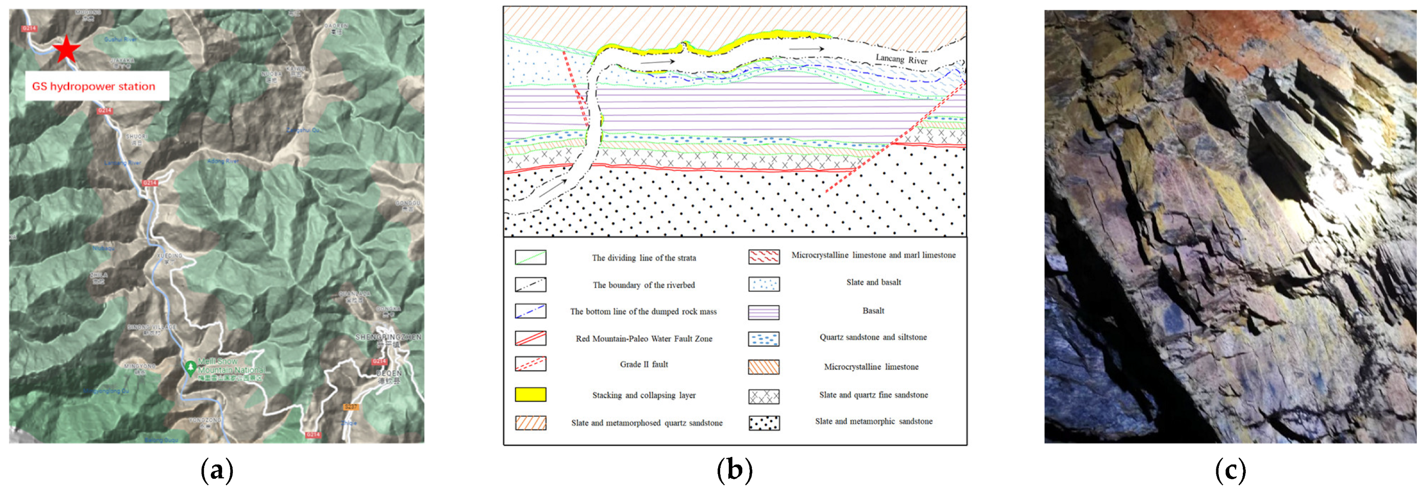
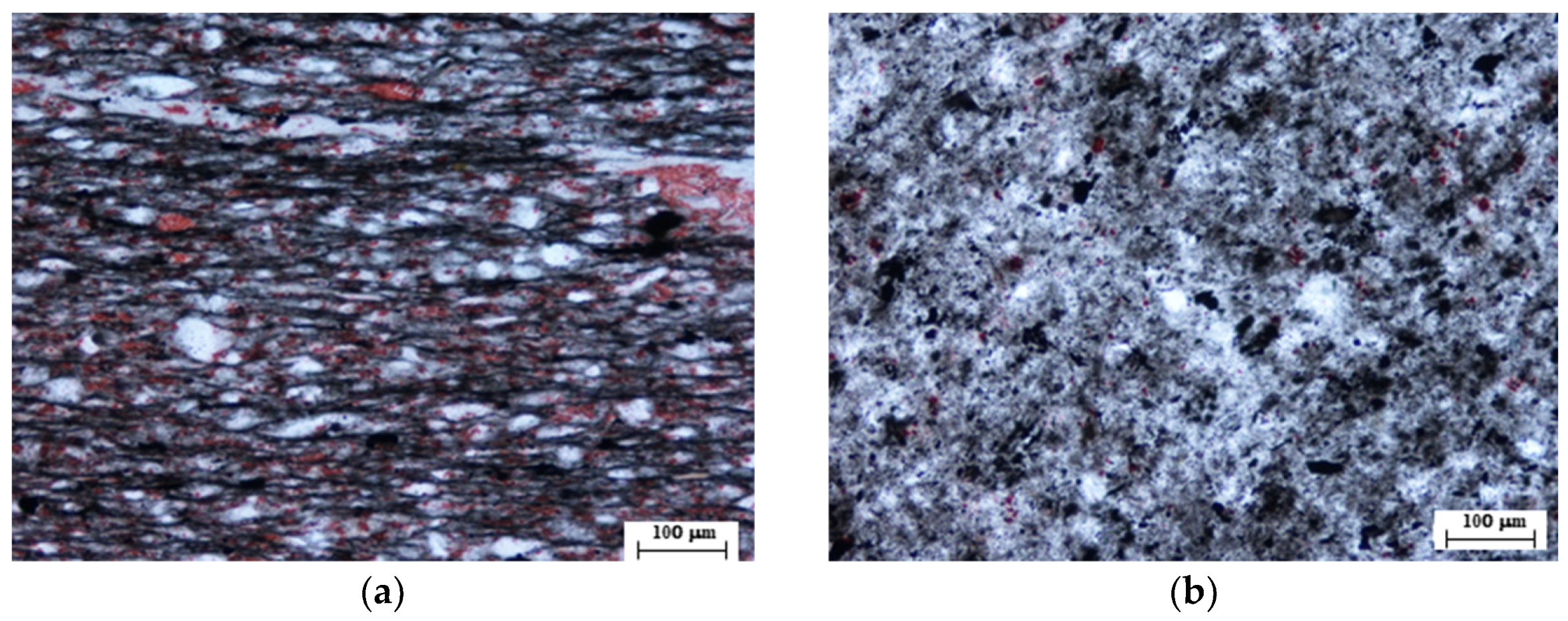
2.1. Materials
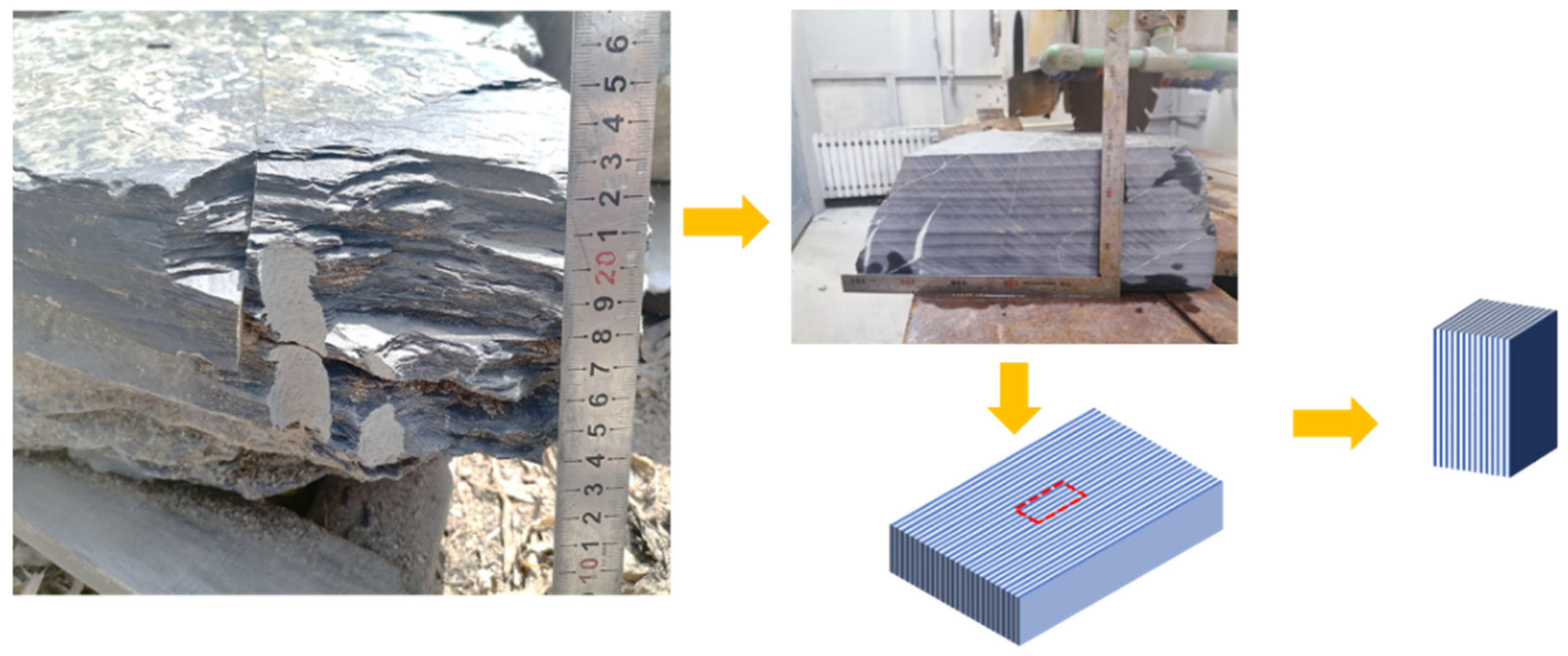
2.2. Preparations for Fragile-Layered Hard Rock Sample
2.3. Testing Equipment
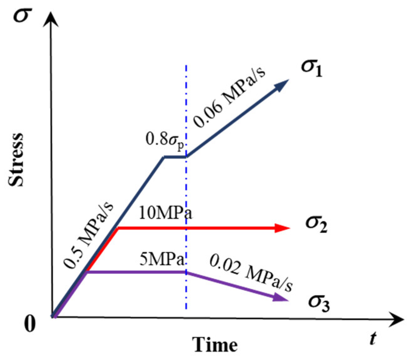
2.4. Experimental Procedures
3. Results and Analysis
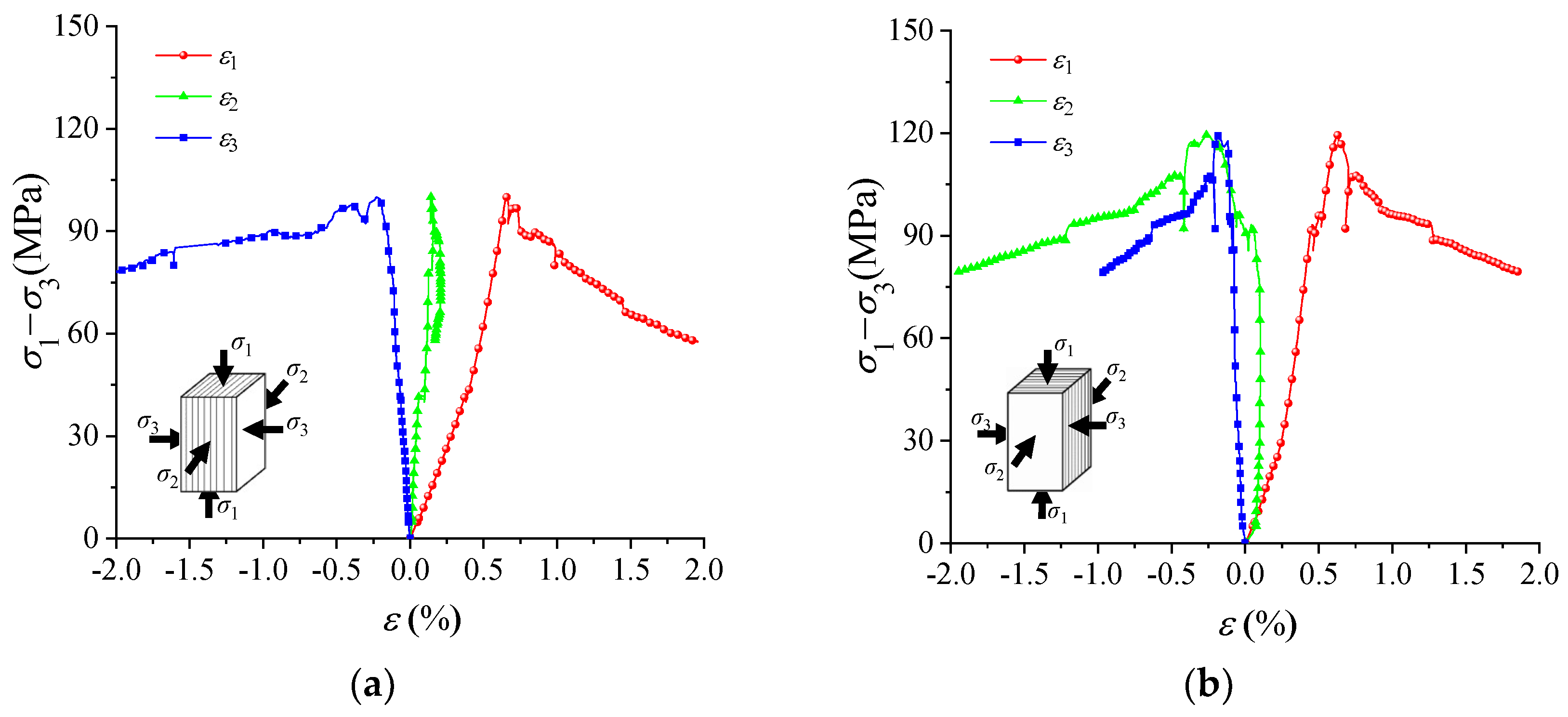
3.1. Traditional True Triaxial Compression Tests
3.2. Engineering Triaxial Stress Path Tests
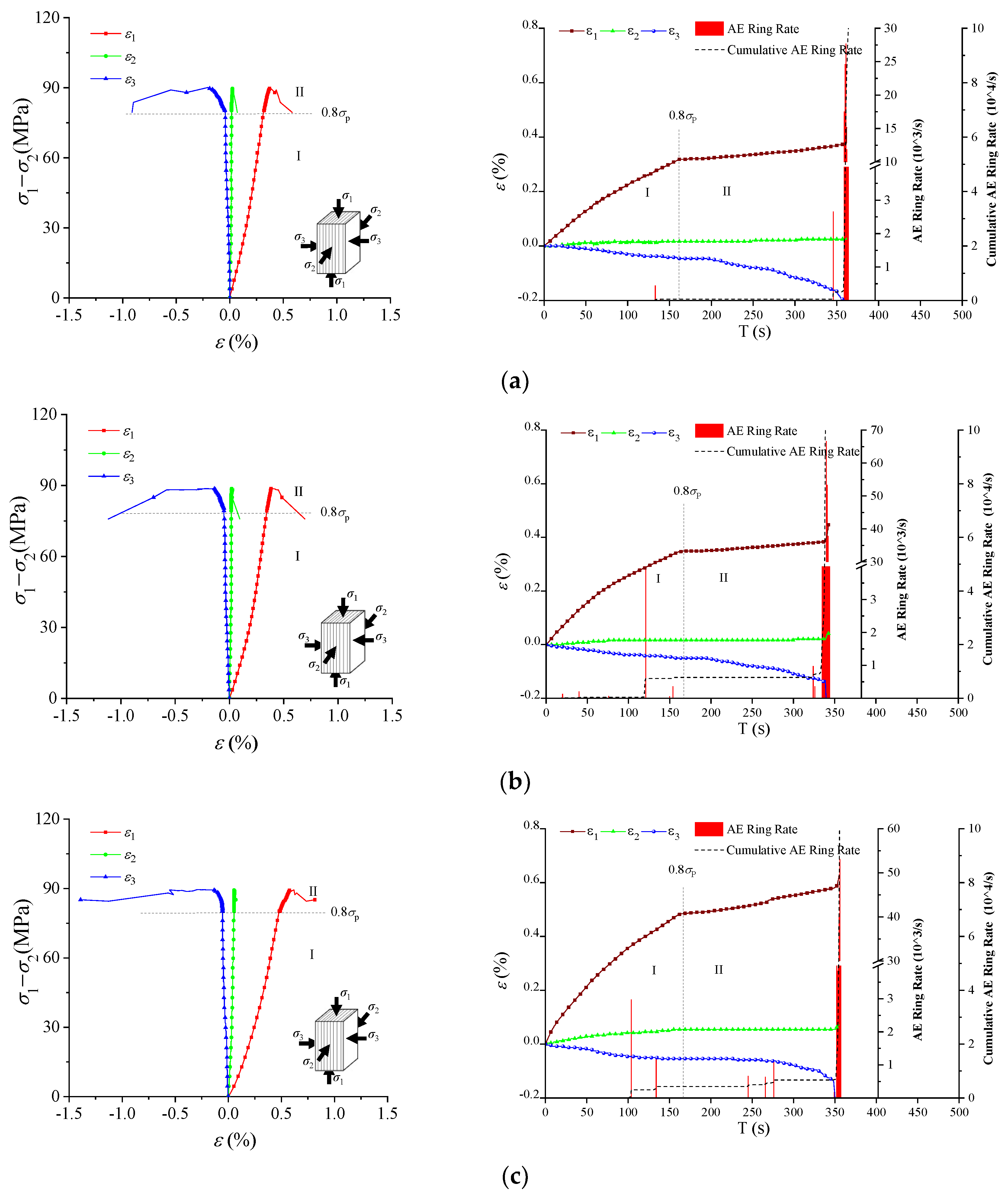
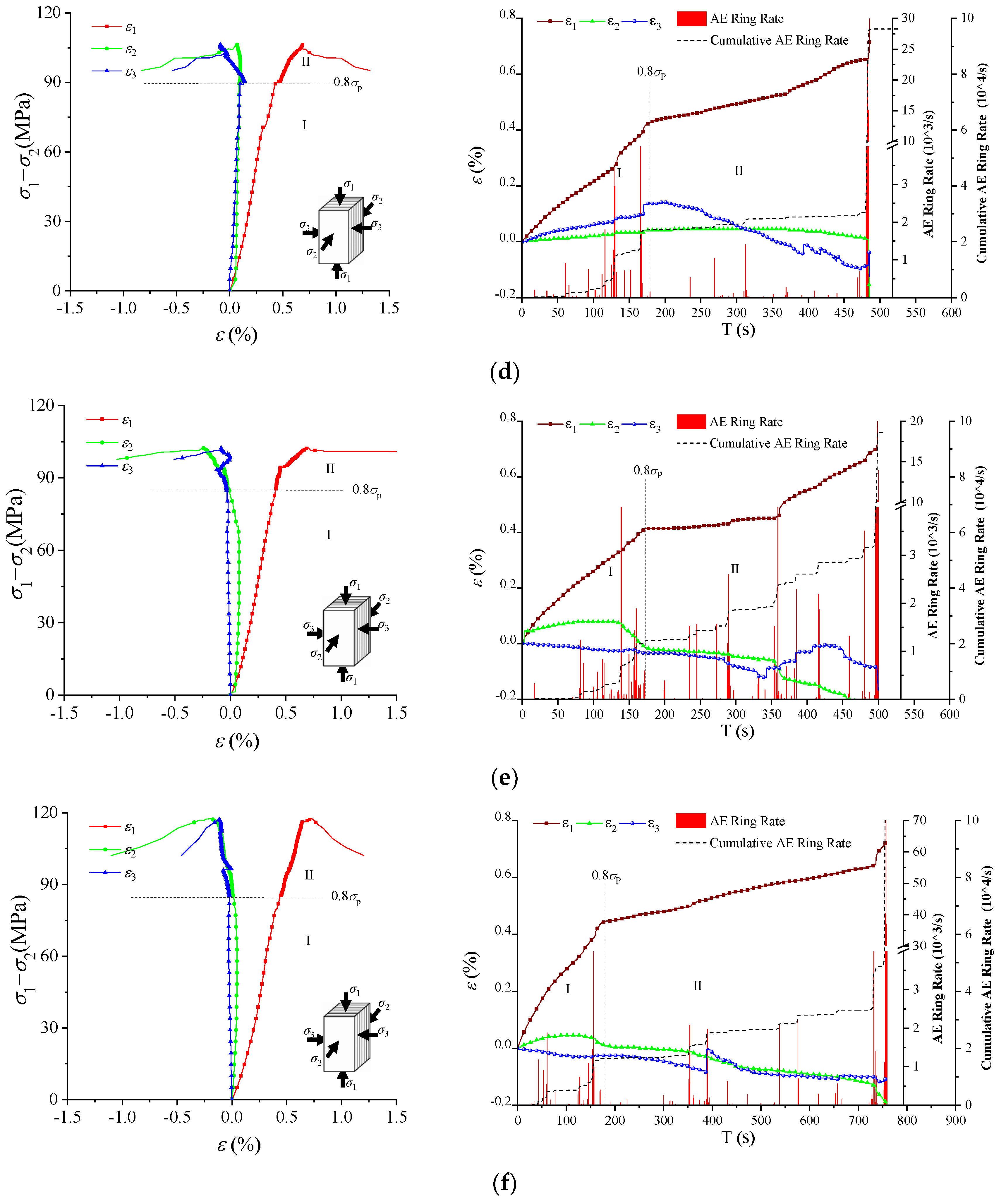
3.2.1. Deformation and AE Characteristics
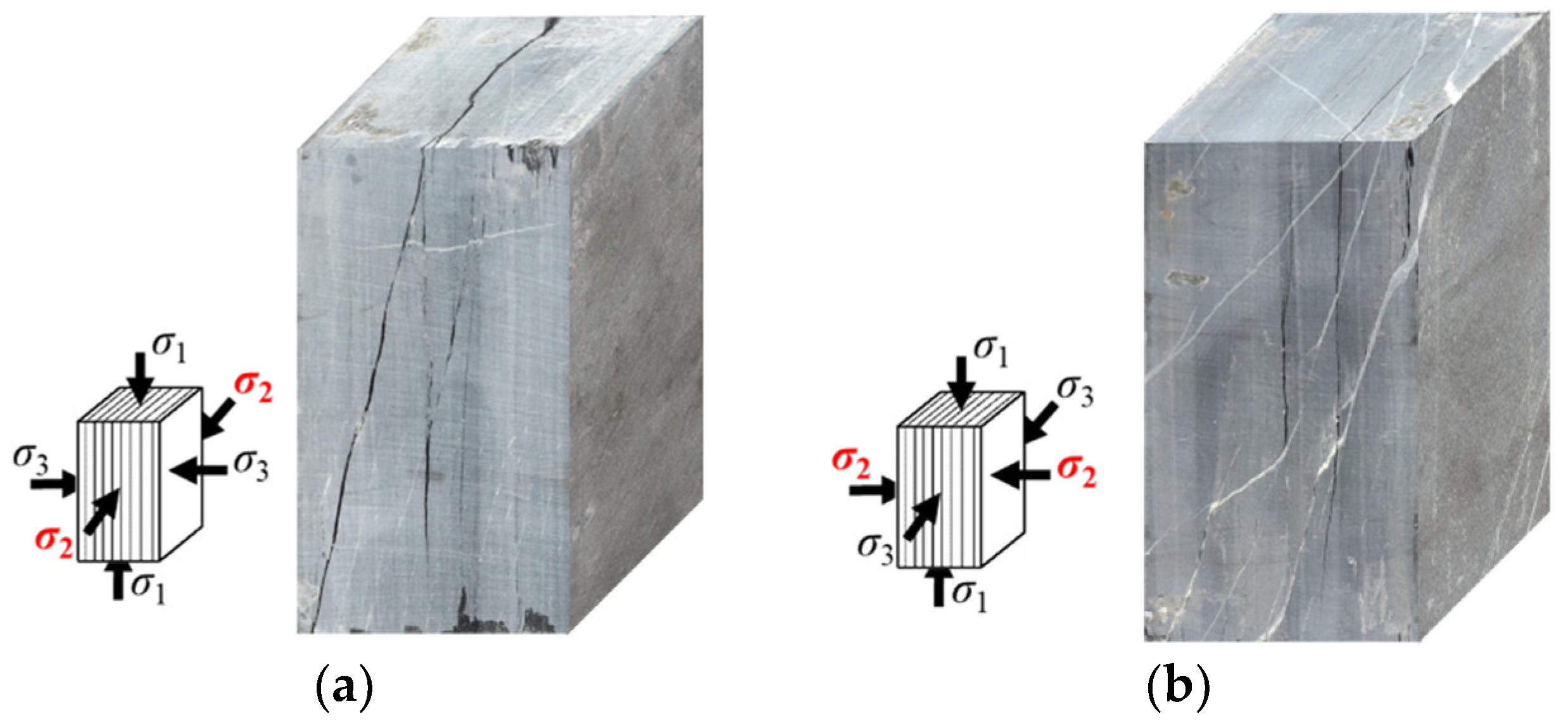
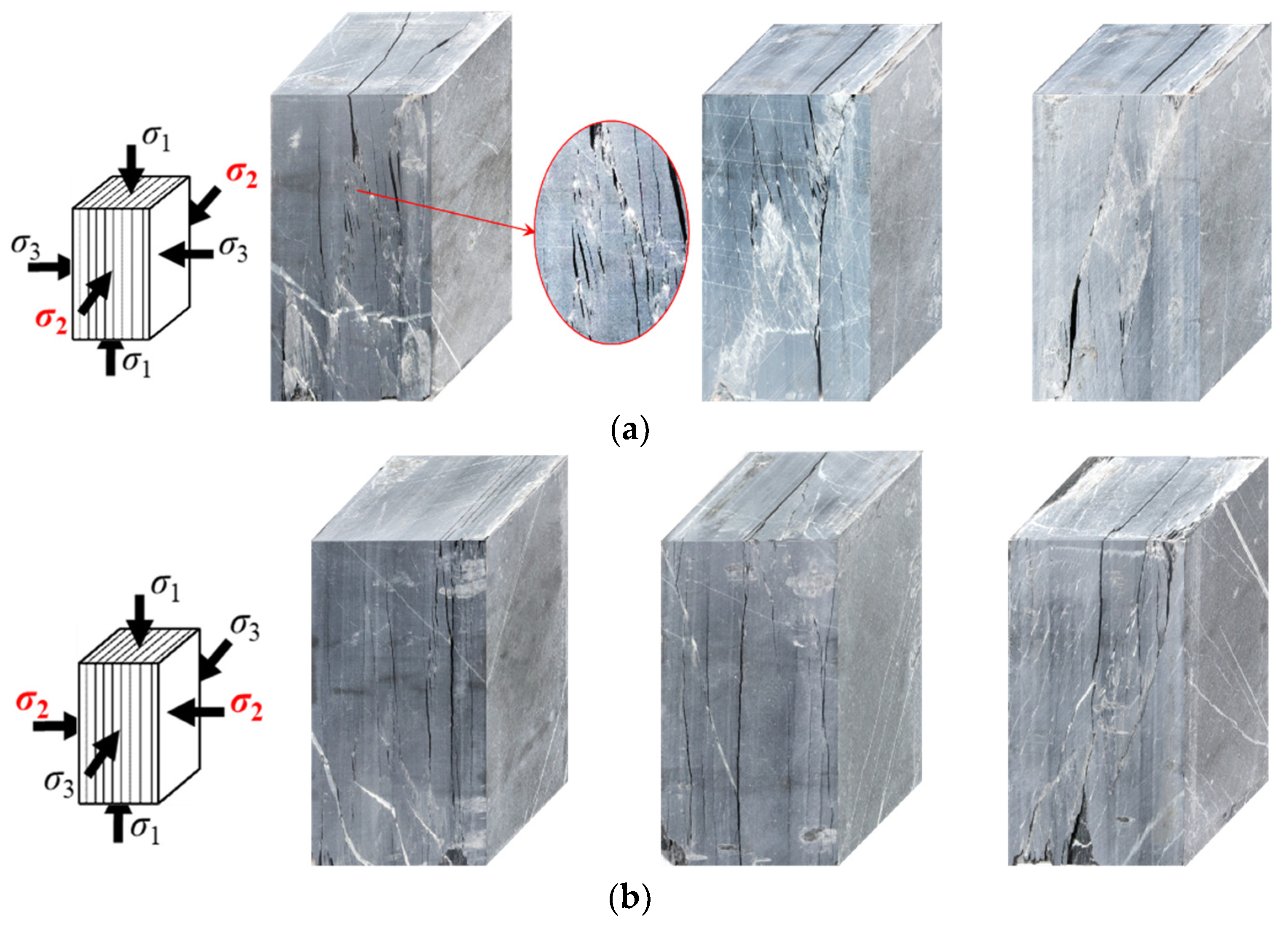
3.2.2. Strength and Failure Characteristics
4. Discussions
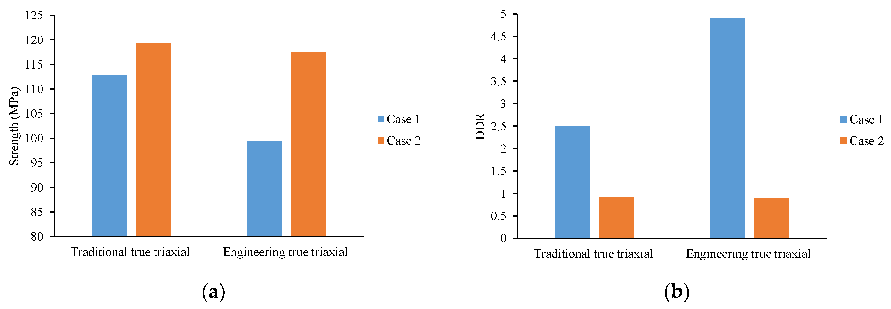
4.1. Comparisons between Traditional and Engineering True Triaxial Stress Paths
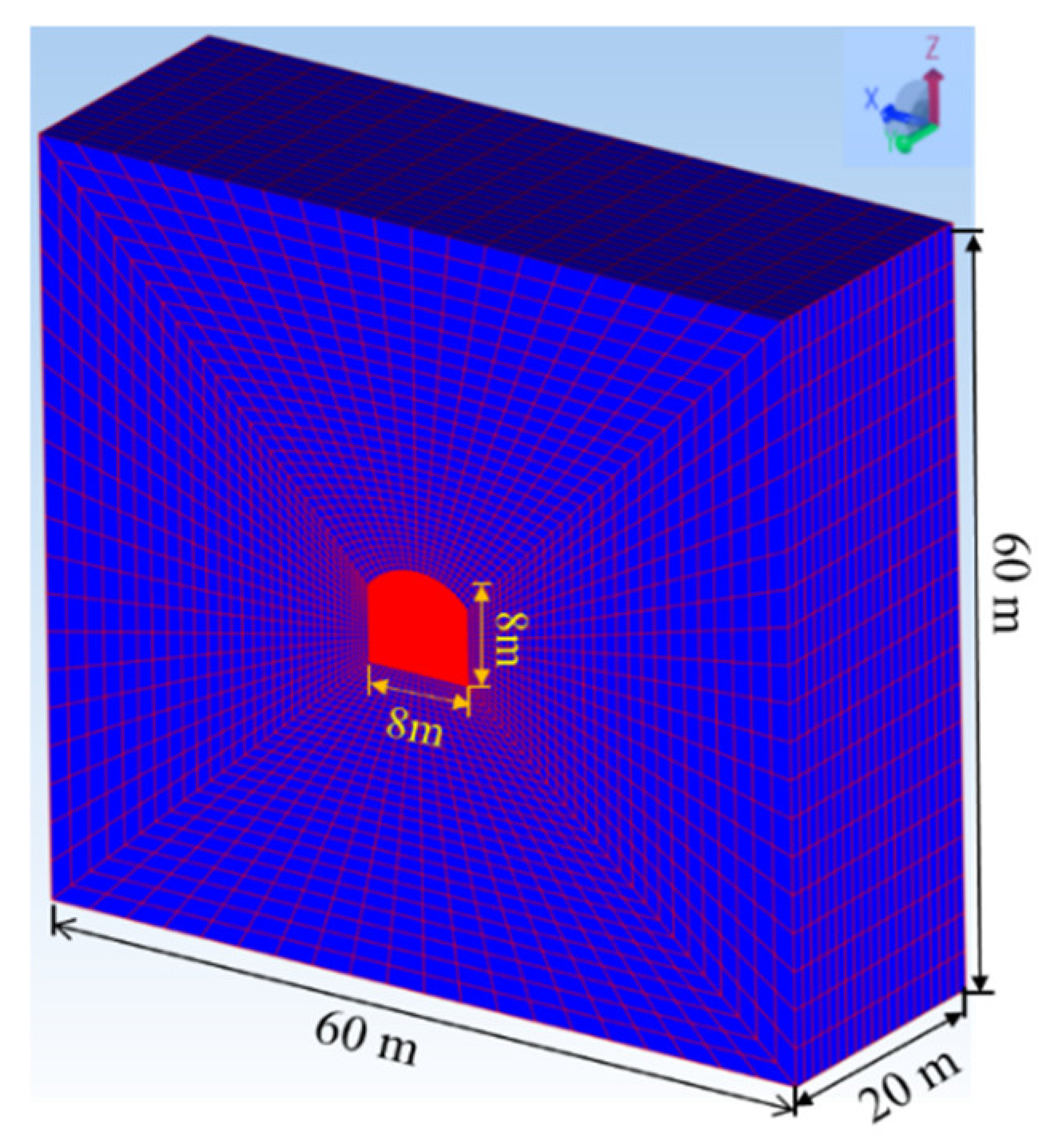
4.2. Numerical Verifications and Engineering Insights
5. Conclusions
- A novel specific small-sample processing method was proposed, designed to accommodate the foliation strike angle. This method minimized rock sample sizes following the ISRM-suggested method to prevent fracturing during processing and testing. By employing a step-by-step rock-sample processing approach, different foliation angles were controlled within the specimens.
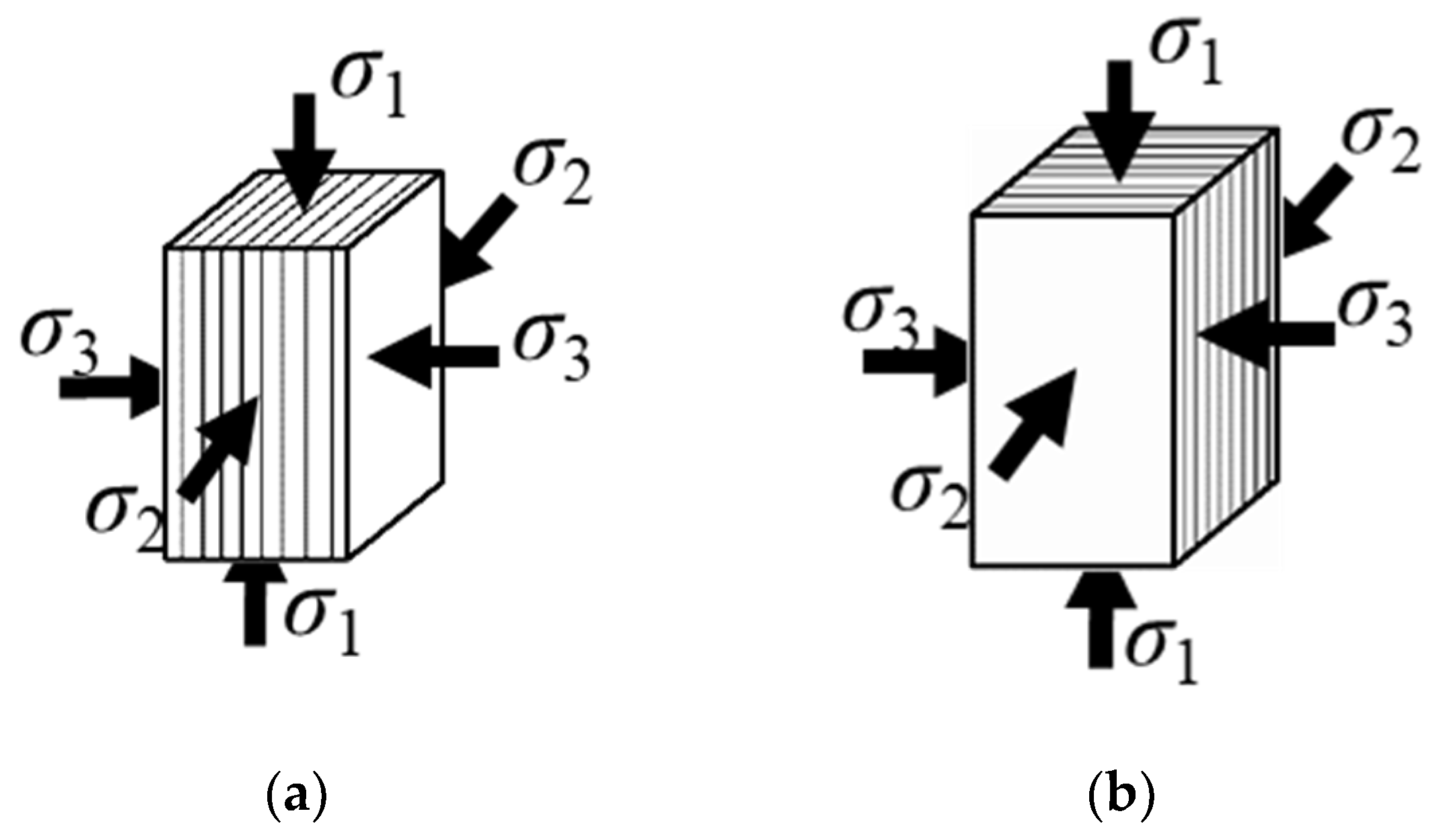
- The study unveiled the foliation strike angle effect of layered hard rock under the engineering triaxial stress path. Diverging from conventional research focusing on foliation angle in the σ1–σ3 plane, the study centered on the foliation strike angle effect within the σ2–σ3 plane. When the foliation was parallel to σ2, the specimen experienced complex multi-scale tension-shear failure, initially with insignificant AE signals indicating potential micro-fractures. Unloading σ3 led to cracks along the foliation edge, causing tensile-shear failure due to limited constraint from σ2. Conversely, when the foliation was parallel to σ3, the specimen exhibited less bearing capacity loss, as independent parallel foliations were still able to bear the load. This failure process evolved gradually, marked by numerous small AE events.
- Comparisons between traditional and engineering true triaxial stress paths demonstrated that irrespective of the foliation direction being parallel to σ3 or σ2, the strength and deformation differences observed under the engineering stress path were more pronounced than those under the conventional true triaxial stress path.
- The numerical simulation results strongly validated the foliation strike angle effect of layered hard rock under the engineering triaxial stress path, confirming the lower strength, greater deformation differences, more abrupt acoustic emission signals, and more severe failure observed when the foliation was parallel to σ2.
Author Contributions
Funding
Institutional Review Board Statement
Informed Consent Statement
Data Availability Statement
Acknowledgments
Conflicts of Interest
References
- Li, B.; Xu, N.; Dai, F.; Zhang, G.; Xiao, P. Dynamic analysis of rock mass deformation in large underground caverns considering microseismic data. Int. J. Rock Mech. Min. Sci. 2019, 122, 104078. [Google Scholar] [CrossRef]
- Xu, D.; Huang, X.; Jiang, Q.; Li, S.; Zheng, H.; Qiu, S.; Xu, H.; Li, Y.; Li, Z.; Ma, X. Estimation of the three-dimensional in situ stress field around a large deep underground cavern group near a valley. J. Rock Mech. Geotech. Eng. 2021, 13, 529–544. [Google Scholar] [CrossRef]
- Liu, X.Y.; Xu, D.P.; Li, S.J.; Qiu, S.L.; Jiang, Q. An Insight into the Mechanical and Fracture Characterization of Minerals and Mineral Interfaces in Granite Using Nanoindentation and Micro X-Ray Computed Tomography. Rock Mech. Rock Eng. 2023, 56, 3359–3375. [Google Scholar] [CrossRef]
- Zhou, Y.Y.; Xu, D.P.; Gu, G.K.; Liu, K.; Wan, L.P.; Wang, T.L.; Yang, J.B. The failure mechanism and construction practice of large underground caverns in steeply dipping layered rock masses. Eng. Geol. 2019, 250, 45–64. [Google Scholar] [CrossRef]
- Xu, D.P.; Feng, X.T.; Chen, D.F.; Zhang, C.Q.; Fan, Q.X. Constitutive representation and damage degree index for the layered rock mass excavation response in underground openings. Tunn. Undergr. Space Technol. 2017, 64, 133–145. [Google Scholar] [CrossRef]
- Feng, X.T.; Xu, H.; Yang, C.X.; Zhang, X.W.; Gao, Y.H. Influence of loading and unloading stress paths on the deformation and failure features of Jinping marble under true triaxial compression. Rock Mech. Rock Eng. 2020, 53, 3287–3301. [Google Scholar] [CrossRef]
- Zheng, Z.; Tang, H.; Zhang, Q.; Pan, P.Z.; Zhang, X.W.; Mei, G.X.; Liu, Z.B.; Wang, W. True triaxial test and PFC3D-GBM simulation study on mechanical properties and fracture evolution mechanisms of rock under high stresses. Comput. Geotech. 2023, 154, 105136. [Google Scholar] [CrossRef]
- Feng, G.L.; Yoshida, S.; Lacidogna, G. Special Issue on New Advances in Acoustic Emission and Microseismic Monitoring Technologies in Civil Engineering. Appl. Sci. 2023, 13, 969. [Google Scholar] [CrossRef]
- Feng, G.L.; Ma, J.; Chen, B.; Xiao, Y.; Jiang, Q.; Li, P.; Lin, M. Microseismic energy and intensity criterion of rockburst in deep TBM tunnels—A case study of the Neelum-Jhelum hydropower project. J. Cent. South Univ. 2023, 30, 1695–1709. [Google Scholar] [CrossRef]
- Guo, H.S.; Sun, Q.C.; Feng, G.L.; Li, S.; Xiao, Y. In-situ observation of damage-fracture evolution in surrounding rocks upon unloading at 2400-m-deep tunnels. Int. J. Min. Sci. Technol. 2023, 33, 437–446. [Google Scholar] [CrossRef]
- Feng, G.L.; Feng, X.T.; Chen, B.R.; Xiao, Y.X.; Yu, Y. A microseismic method for dynamic warning of rockburst development processes in tunnels. Rock Mech. Rock Eng. 2015, 48, 2061–2076. [Google Scholar] [CrossRef]
- Li, S.; Feng, X.T.; Li, Z.; Chen, B.; Zhang, C.; Zhou, H. In situ monitoring of rockburst nucleation and evolution in the deeply buried tunnels of Jinping II hydropower station. Eng. Geol. 2012, 137, 85–96. [Google Scholar] [CrossRef]
- Eberhardt, E. Numerical modelling of three-dimension stress rotation ahead of an advancing tunnel face. Int. J. Rock Mech. Min. 2001, 38, 499–518. [Google Scholar] [CrossRef]
- Li, D.Y.; Sun, Z.; Xie, T.; Li, X.B.; Ranjith, P.G. Energy evolution characteristics of hard rock during triaxial failure with different loading and unloading paths. Eng. Geol. 2017, 228, 270–281. [Google Scholar] [CrossRef]
- Zhou, H.; Liang, C.K.; Wang, Z.C. Simulating the variation of surrounding rock and analyzing the disturbed stress field during excavation of deep mine roadway. Chin. J. Rock Mech. Eng. 2017, 36, 1821–1831. [Google Scholar] [CrossRef]
- Feng, X.T.; Haimson, B.; Li, X.C.; Chang, C.D.; Ma, X.D.; Zhang, X.W.; Ingraham, M.; Suzuki, K. ISRM Suggested Method: Determining Deformation and Failure Characteristics of Rocks Subjected to True Triaxial Compression. Rock Mech. Rock Eng. 2019, 52, 2011–2020. [Google Scholar] [CrossRef]
- Bai, Q.S.; Young, R.P. Numerical investigation of the mechanical and damage behaviors of veined gneiss during true-triaxial stress path loading by simulation of in situ conditions. Rock. Mech. Rock. Eng. 2020, 53, 133–151. [Google Scholar] [CrossRef]
- Qiu, S.L.; Feng, X.T.; Xiao, J.Q.; Zhang, C.Q. An experimental study on the pre-peak unloading damage evolution of marble. Rock. Mech. Rock. Eng. 2014, 47, 401–419. [Google Scholar] [CrossRef]
- He, M.C.; Nie, W.; Zhao, Z.Y.; Cheng, C. Micro-and macro-fractures of coarse granite under true-triaxial unloading conditions. Min. Sci. Technol. 2011, 21, 389–394. [Google Scholar] [CrossRef]
- Li, X.; Du, K.; Li, D. True triaxial strength and failure modes of cubic rock specimens with unloading the minor principal stress. Rock Mech. Rock Eng. 2015, 48, 2185–2196. [Google Scholar] [CrossRef]
- Zhang, X.P.; Wong, L.N.Y.; Wang, S.J.; Han, G.Y. Engineering properties of quartz mica schist. Eng. Geol. 2011, 121, 135–149. [Google Scholar] [CrossRef]
- Gatelier, N.; Pellet, F.; Loret, B. Mechanical damage of an anisotropic porous rock in cyclic triaxial tests. Int. J. Rock Mech. Min. Sci. 2002, 39, 335–354. [Google Scholar] [CrossRef]
- Xiroudakis, G.; Stavropoulou, M.; Exadaktylos, G. Three-dimensional elastic analysis of cracks with the g2 constant displacement discontinuity method. Int. J. Numer. Anal. Methods Geomech. 2019, 43, 2355–2382. [Google Scholar] [CrossRef]
- Wang, S.; Wang, L.; Tian, J.; Fan, H.; Jiang, C.; Ding, K. An Experimental Study on the Effects of True Triaxial Loading and Unloading Stress Paths on the Mechanical Properties of Red Sandstone. Minerals 2022, 12, 204. [Google Scholar] [CrossRef]
- Onyelowe, K.C.; Ebid, A.M.; Sujatha, E.R.; Fazel-Mojtahedi, F.; Golaghaei-Darzi, A.; Kontoni, D.P.N.; Nooralddin-Othman, N. Extensive overview of soil constitutive relations and applications for geotechnical engineering problems. Heliyon 2023, 9, e14465. [Google Scholar] [CrossRef] [PubMed]
- Mehmood, E.; Rashid, I.; Ahmed, F.; Farooq, K.; Tufail, A.; Ebid, A.M. Hydrogeotechnical Predictive Approach for Rockfall Mountain Hazard Using Elastic Modulus and Peak Shear Stress at Soil–Rock Interface in Dry and Wet Phases at KKH Pakistan. Sustainability 2022, 14, 16740. [Google Scholar] [CrossRef]
- Zhou, Y.Y.; Xu, D.P.; Liu, K.; Chen, D.F. Understanding the failure mechanism of a large underground cavern in steeply dipping layered rock mass using an enhanced ubiquitous-joint model. Bull. Eng. Geol. Environ. 2021, 80, 4621–4638. [Google Scholar] [CrossRef]
- Zhang, J.C.; Zhou, S.H.; Lin, Z.N.; Han, C.X. Using the Pietruszczak-Mroz anisotropic failure criterion to model the strength of stratified rocks. Int. J. Rock Mech. Min. Sci. 2020, 130, 104312. [Google Scholar] [CrossRef]
- Pietruszczak, S.; Haghighat, E. Modeling of deformation and localized failure in anisotropic rocks. Int. J. Solids Struct. 2015, 67, 93–101. [Google Scholar] [CrossRef]
- Wang, Z.; Pan, P.Z.; Liu, X.; Zhou, Y.; Hou, W.; Yang, S. A Hybrid Anisotropic Elastoplastic Model for Layered Rock Mass and Numerical Implementation. Int. J. Geomech. 2023, 23, 04023019. [Google Scholar] [CrossRef]
- Wu, M.; Wang, J. Constitutive modelling of natural sands using a deep learning approach accounting for particle shape effects. Powder Technol. 2022, 404, 117439. [Google Scholar] [CrossRef]
- Wu, M.; Xia, Z.; Wang, J. Constitutive modelling of idealised granular materials using machine learning method. J. Rock Mech. Geotech. Eng. 2023, 15, 1038–1051. [Google Scholar] [CrossRef]
- Liu, X.; Feng, X.T.; Zhou, Y. Experimental study of mechanical behavior of gneiss considering the orientation of schistosity under true triaxial compression. Int. J. Geomech. 2020, 20, 04020199. [Google Scholar] [CrossRef]
- Mogi, K. Fracture and flow of rocks under high triaxial compression. J. Geophys. Res. 1971, 76, 1255–1269. [Google Scholar] [CrossRef]
- Haimson, B.; Chang, C. A new true triaxial cell for testing mechanical properties of rock, and its use to determine rock strength and deformability of Westerly granite. Int. J. Rock Mech. Min. Sci. 2000, 37, 285–296. [Google Scholar] [CrossRef]
- Takahashi, M.; Koide, H. Effect of the intermediate principal stress on strength and deformation behavior of sedimentary rocks at the depth shallower than 2000 m. In Proceedings of the ISRM International Symposium, Pau, France, 30 August–2 September 1989. [Google Scholar]
- Feng, X.T.; Wang, Z.; Zhou, Y.; Yang, C.; Pan, P.Z.; Kong, R. Modelling three-dimensional stress-dependent failure of hard rocks. Acta Geotech. 2021, 16, 1647–1677. [Google Scholar] [CrossRef]


| Orientation of Foliation | Test Type | Initial Stress Regime | ||||
|---|---|---|---|---|---|---|
| Loading Angle | β (°) | ω (°) | σ3 (MPa) | σ2 (MPa) | σ1 (MPa) | |
| Case I | 0 | 0 | Loading | 5 | 10 | \ |
| 0 | 0 | Loading and unloading | 5 | 10 | 0.8 σp | |
| Case II | 0 | 90 | Loading | 5 | 10 | \ |
| 0 | 90 | Loading and unloading | 5 | 10 | 0.8 σp | |
| Loading Angle | Strength of Each Specimen | Average Strength σp | |||
|---|---|---|---|---|---|
| β (°) | ω (°) | (MPa) | (MPa) | ||
| 0 | 0 | 102.5 | 115.1 | 120.8 | 112.8 |
| 0 | 90 | 129.4 | 124.4 | 104.2 | 119.3 |
| Loading Angle | No. | Final Stress Level | |||
|---|---|---|---|---|---|
| β (°) | ω (°) | σ3 (MPa) | σ2 (MPa) | σ1 (MPa) | |
| 0 | 0 | 1 | 1.6 | 10 | 100.1 |
| 2 | 2.1 | 10 | 98.6 | ||
| 3 | 1.8 | 10 | 99.6 | ||
| 0 | 90 | 1 | 0 | 10 | 111.9 |
| 2 | 0 | 10 | 112.6 | ||
| 3 | 0 | 10 | 127.7 | ||
| σxx (MPa) | σyy (MPa) | σzz (MPa) | σxy (MPa) | σyz (MPa) | σxz (MPa) |
|---|---|---|---|---|---|
| 14.59 | 24.92 | 21.99 | −1.48 | 2.68 | 2.32 |
| E1 (GPa) | E3 (GPa) | ν11 | ν13 | G13 (GPa) | ρ (kg/m3) |
| 11.55 | 6.27 | 0.2 | 0.4 | 2.38 | 2500 |
| c0 (MPa) | φ0 (°) | cr (MPa) | φr (°) | σt (MPa) | σr (MPa) |
| 28.00 | 21 | 1.00 | 26 | 1.00 | 0.10 |
Disclaimer/Publisher’s Note: The statements, opinions and data contained in all publications are solely those of the individual author(s) and contributor(s) and not of MDPI and/or the editor(s). MDPI and/or the editor(s) disclaim responsibility for any injury to people or property resulting from any ideas, methods, instructions or products referred to in the content. |
© 2023 by the authors. Licensee MDPI, Basel, Switzerland. This article is an open access article distributed under the terms and conditions of the Creative Commons Attribution (CC BY) license (https://creativecommons.org/licenses/by/4.0/).
Share and Cite
Wang, Z.; Feng, G.; Liu, X.; Zhou, Y. An Experimental Investigation on the Foliation Strike-Angle Effect of Layered Hard Rock under Engineering Triaxial Stress Path. Materials 2023, 16, 5987. https://doi.org/10.3390/ma16175987
Wang Z, Feng G, Liu X, Zhou Y. An Experimental Investigation on the Foliation Strike-Angle Effect of Layered Hard Rock under Engineering Triaxial Stress Path. Materials. 2023; 16(17):5987. https://doi.org/10.3390/ma16175987
Chicago/Turabian StyleWang, Zhaofeng, Guangliang Feng, Xufeng Liu, and Yangyi Zhou. 2023. "An Experimental Investigation on the Foliation Strike-Angle Effect of Layered Hard Rock under Engineering Triaxial Stress Path" Materials 16, no. 17: 5987. https://doi.org/10.3390/ma16175987