
Effect of Austempering Processes on the Tensile Properties and the Work-Hardening Behavior of Austempered Bainitic Steels Below the Martensite Start Temperature
Abstract
:1. Introduction
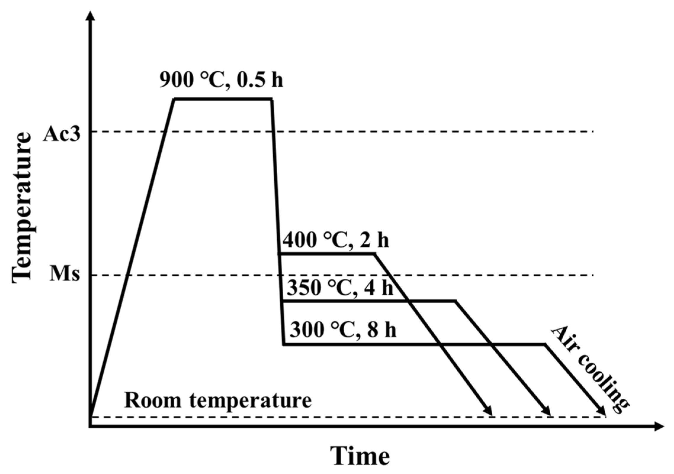
2. Materials and Methods
3. Results and Discussions
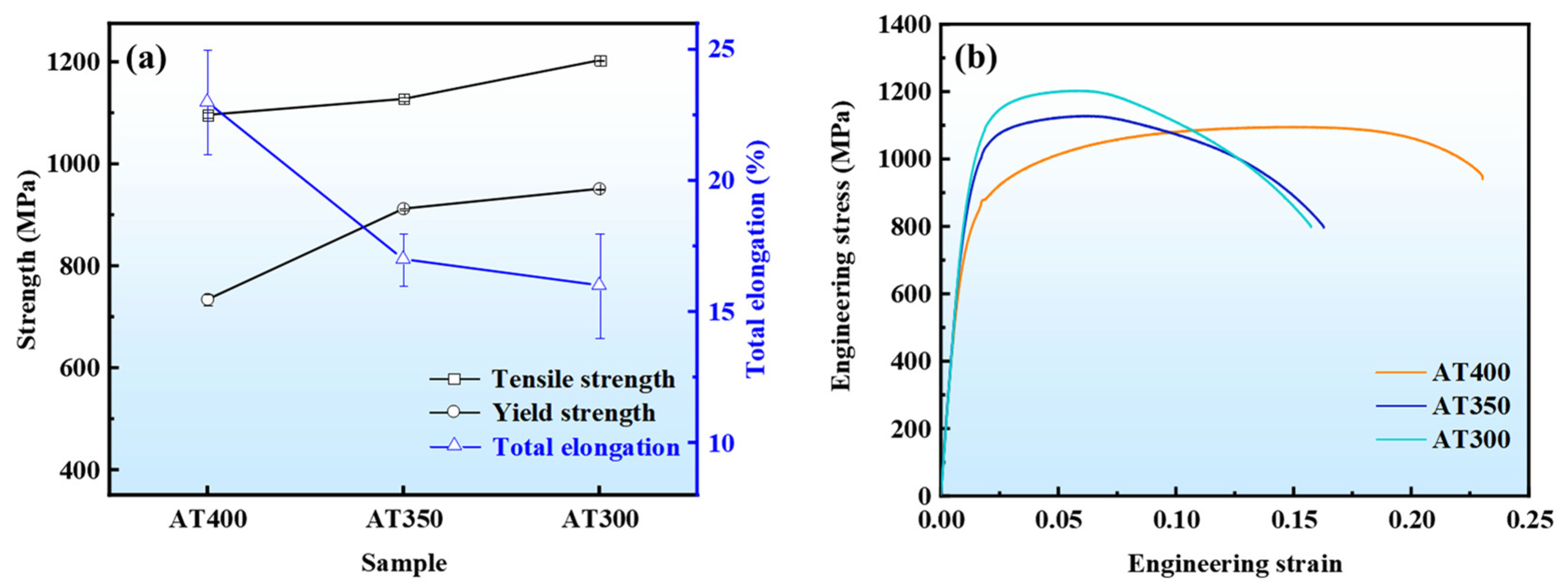
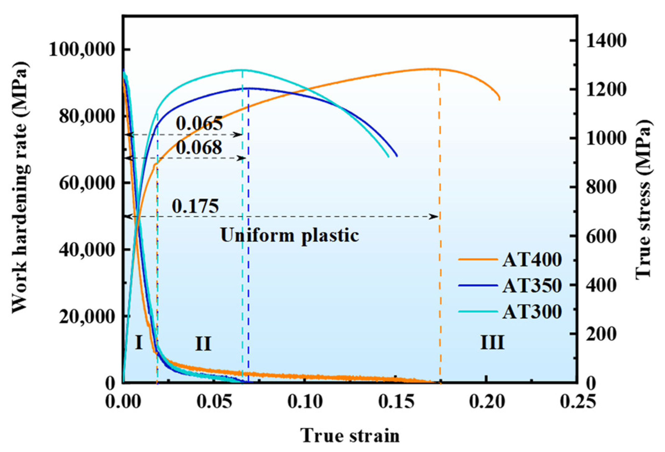
3.1. Mechanical Properties
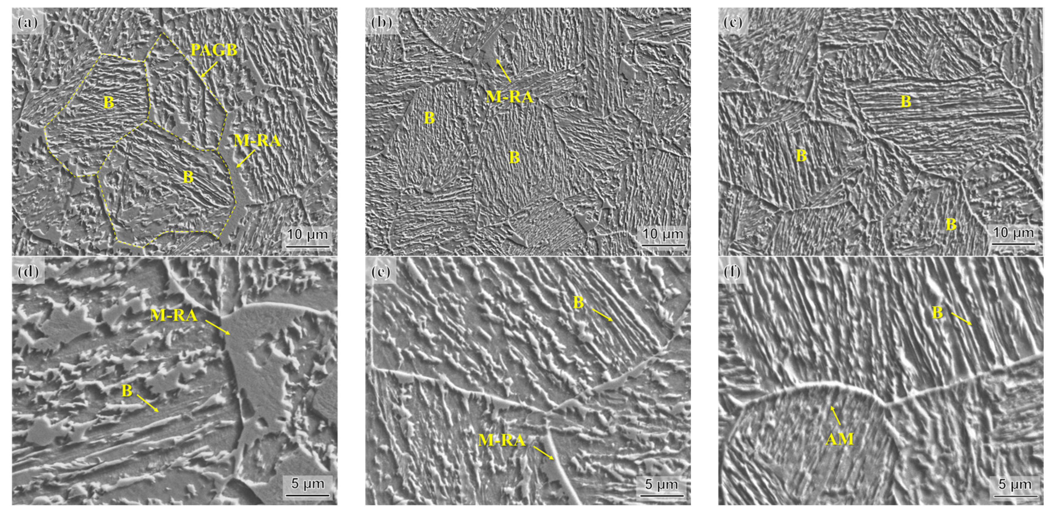
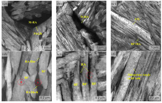
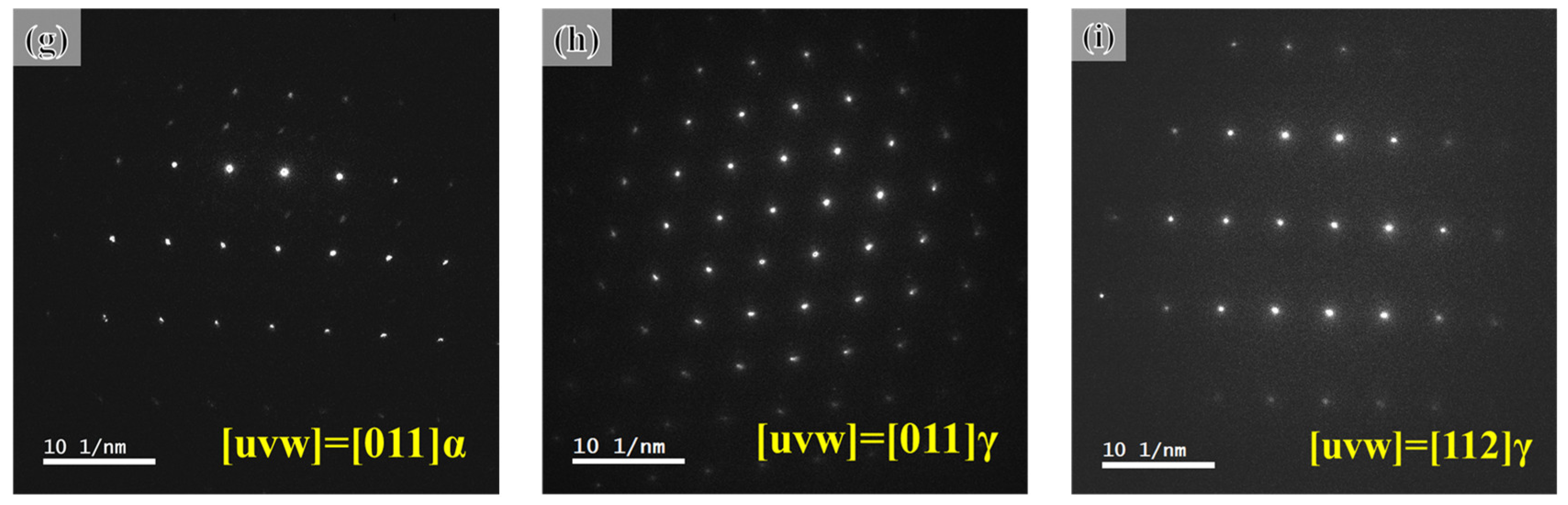
3.2. Microstructure
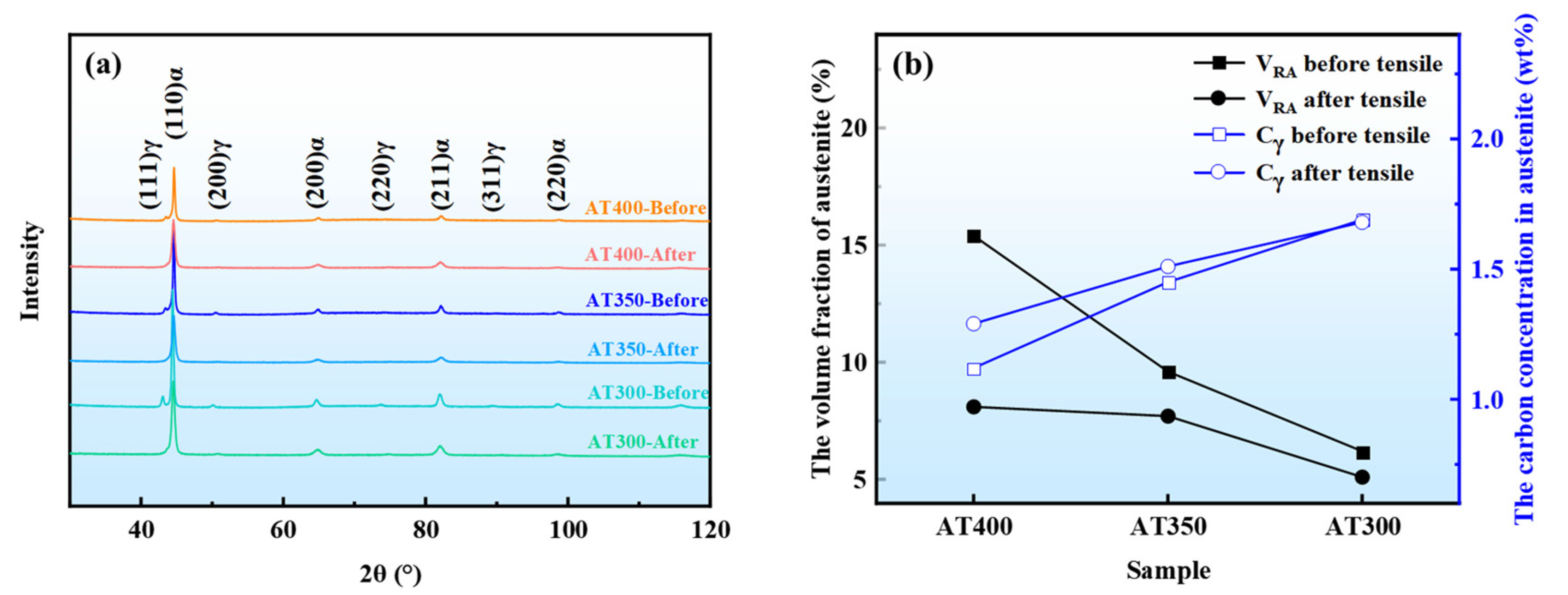
3.3. XRD Analysis
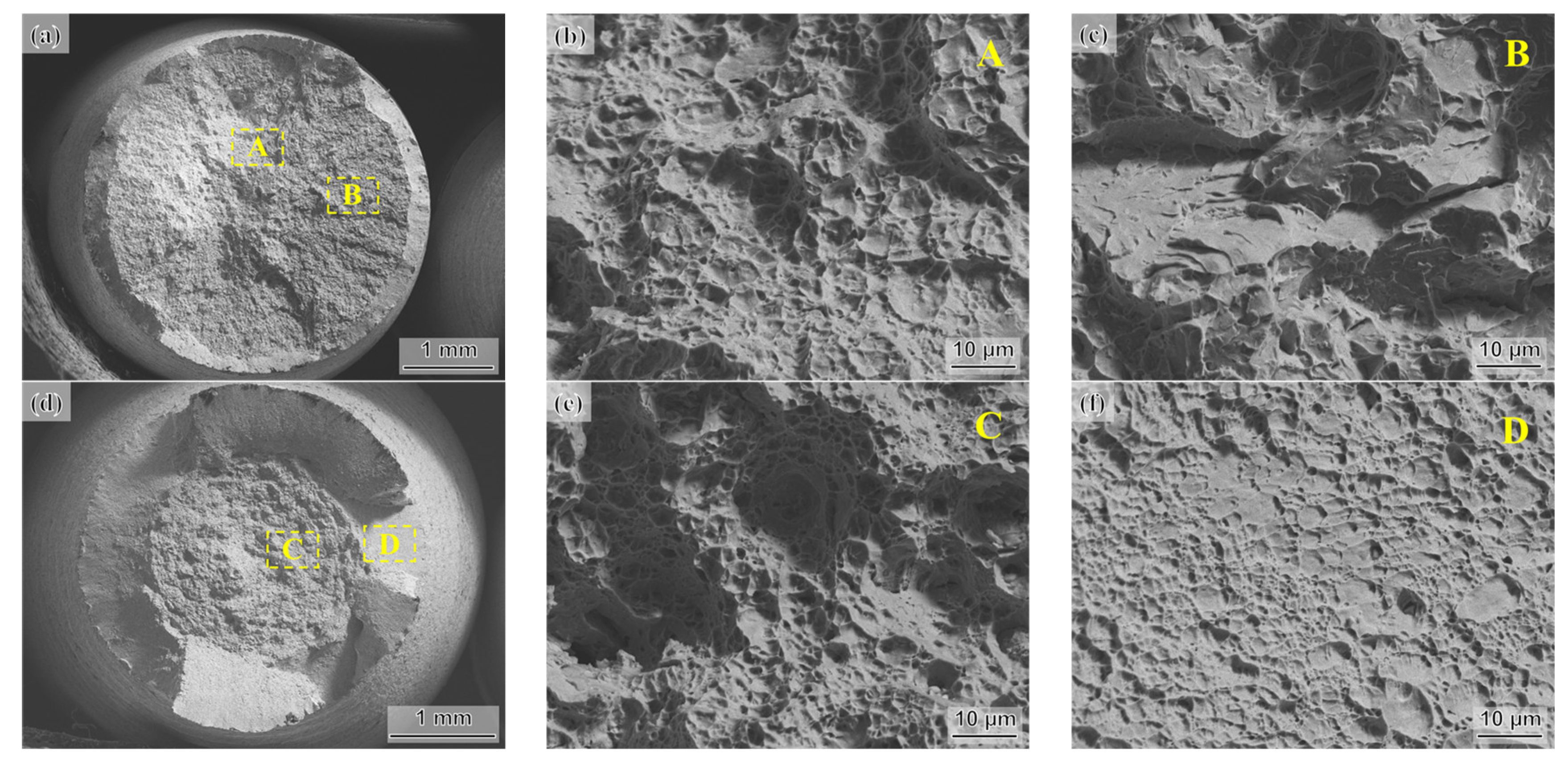
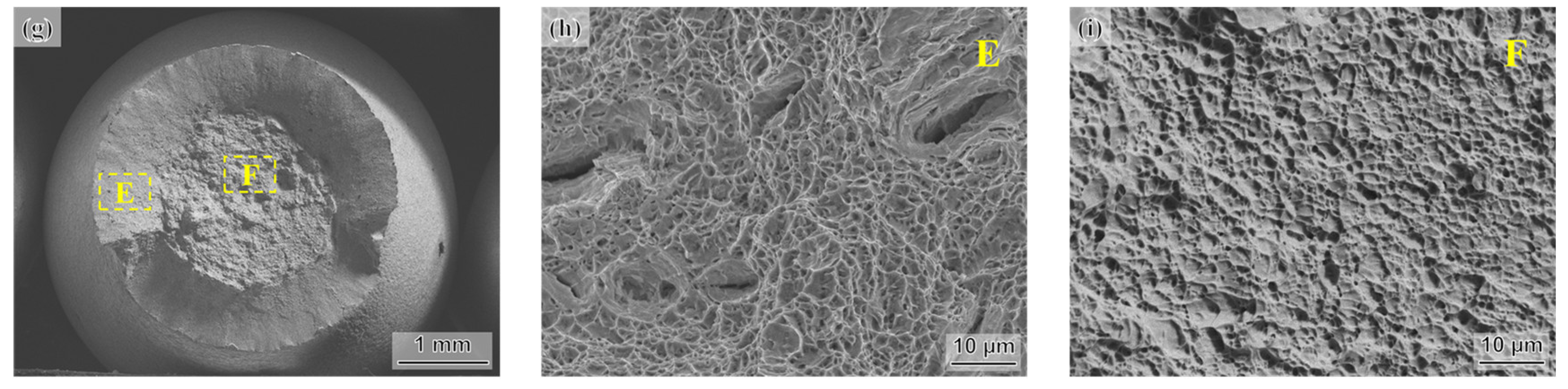
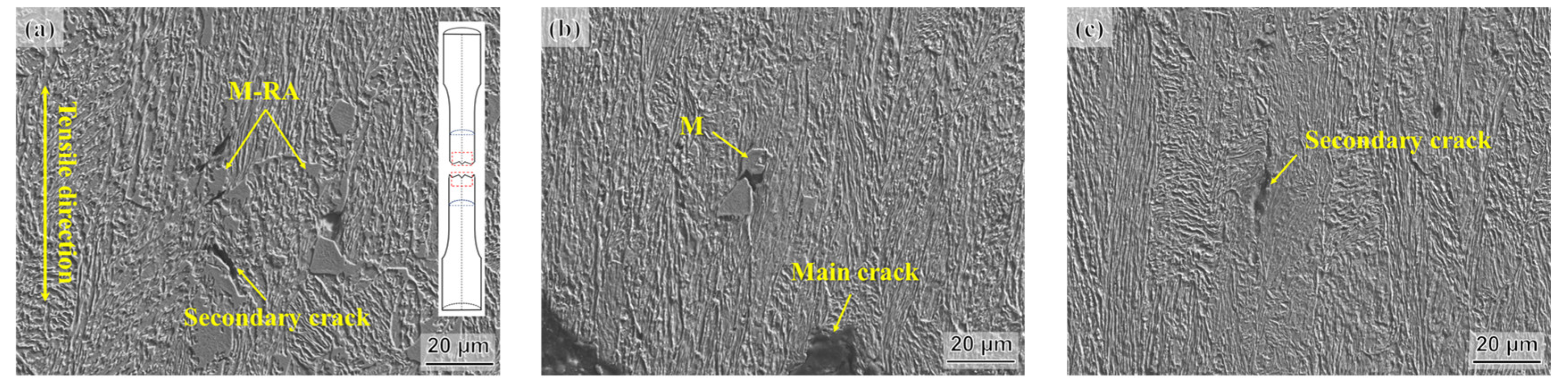
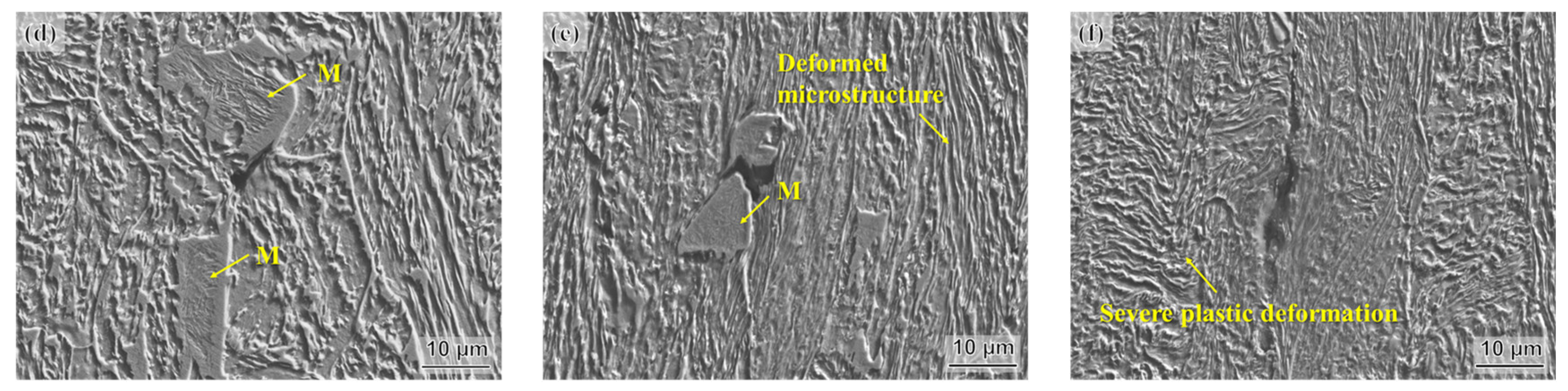
3.4. Tensile Fracture Morphology
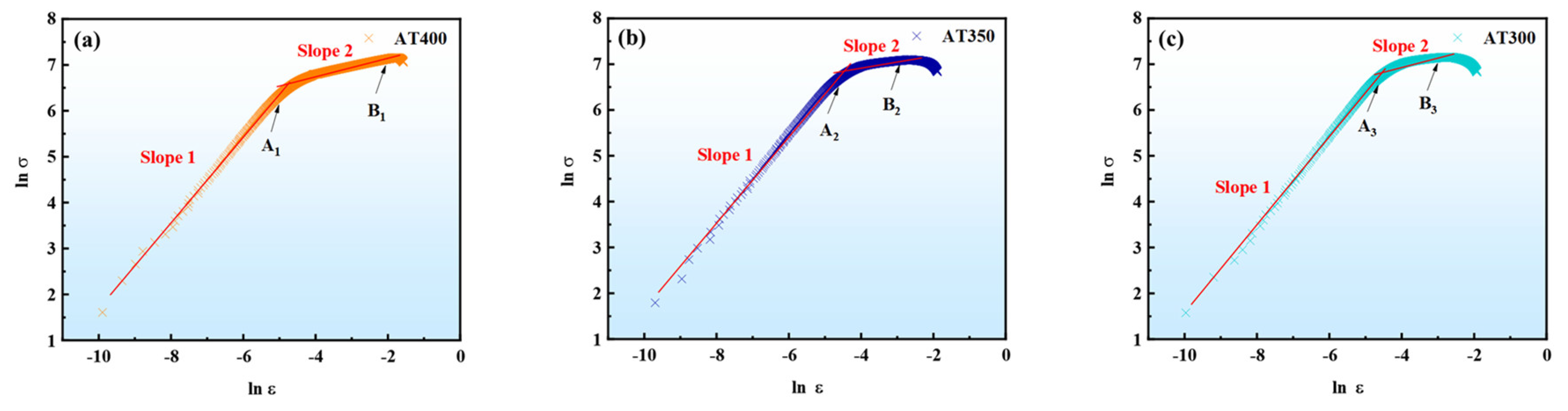
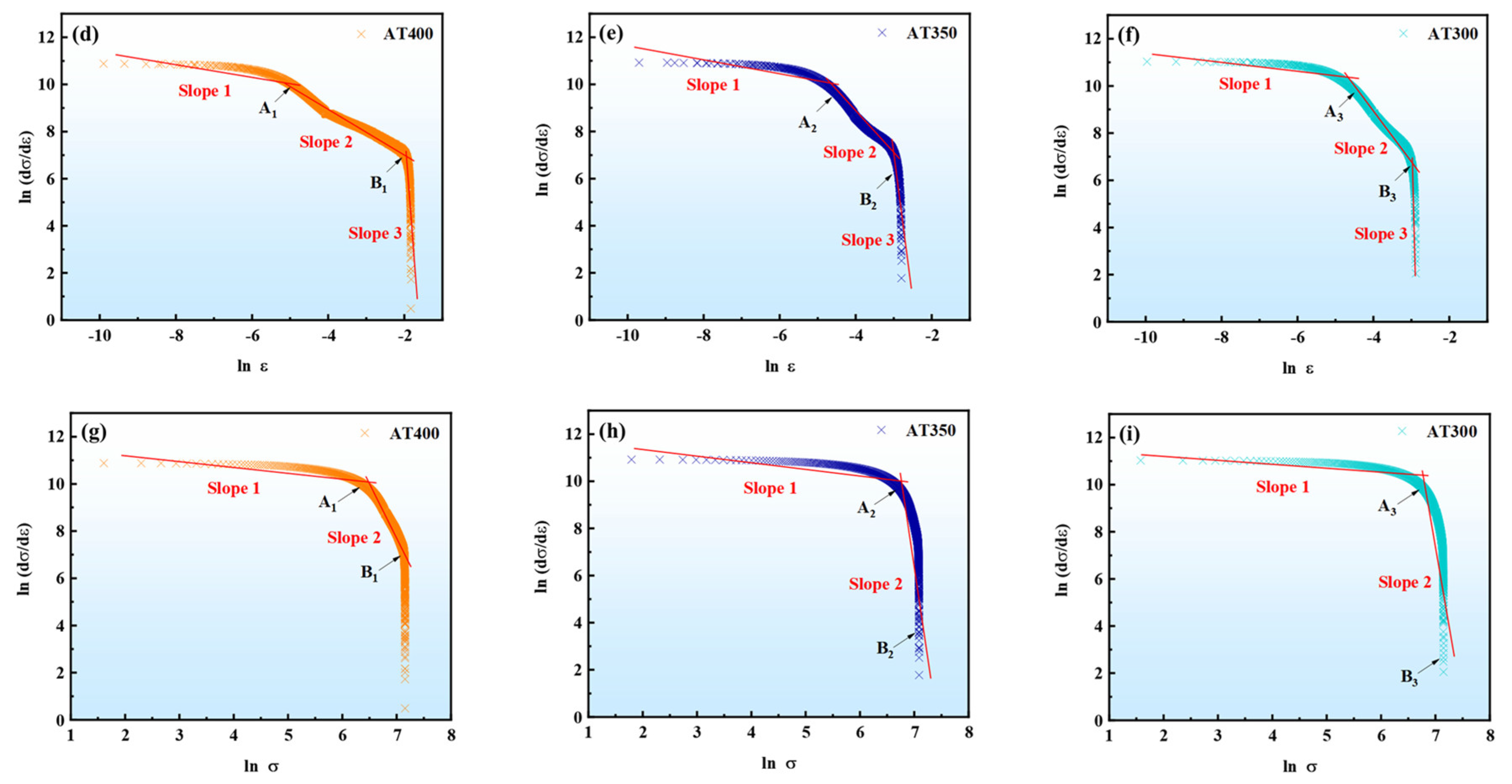
3.5. Theoretical Model of the Work-Hardening Behavior
4. Conclusions
Author Contributions
Funding
Institutional Review Board Statement
Informed Consent Statement
Data Availability Statement
Acknowledgments
Conflicts of Interest
References
- Caballero, F.G.; Bhadeshia, H.K.D.H. Very strong bainite. Curr. Opin. Solid State Mater. Sci. 2004, 8, 251–257. [Google Scholar] [CrossRef] [Green Version]
- Lan, H.F.; Du, L.X.; Li, Q.; Qiu, C.L.; Li, J.P.; Misra, R.D.K. Improvement of strength-toughness combination in austempered low carbon bainitic steel: The key role of refining prior austenite grain size. J. Alloys Compd. 2017, 710, 702–710. [Google Scholar]
- Long, X.Y.; Zhang, F.C.; Yang, Z.N.; Lv, B. Study on microstructures and properties of carbide-free and carbide-bearing bainitic steels. Mater. Sci. Eng. A 2018, 715, 10–16. [Google Scholar] [CrossRef]
- Luo, H.W.; Wang, X.H.; Liu, Z.B.; Yang, Z.Y. Influence of refined hierarchical martensitic microstructures on yield strength and impact toughness of ultra-high strength stainless steel. J. Mater. Sci. Technol. 2020, 51, 130–136. [Google Scholar] [CrossRef]
- Zhou, S.B.; Hu, F.; Zhou, W.; Cheng, L.; Hu, C.Y.; Wu, K.M. Effect of retained austenite on impact toughness and fracture behavior of medium carbon submicron-structured bainitic steel. J. Mater. Res. Technol. 2021, 14, 1021–1034. [Google Scholar] [CrossRef]
- Kumar, A.; Singh, A. Mechanical properties of nanostructured bainitic steels. Materialia 2021, 15, 101034. [Google Scholar] [CrossRef]
- Gao, G.; Zhang, H.; Gui, X.; Luo, P.; Tan, Z.; Bai, B. Enhanced ductility and toughness in an ultrahigh-strength Mn–Si–Cr–C steel: The great potential of ultrafine filmy retained austenite. Acta Mater. 2014, 76, 425–433. [Google Scholar]
- Zhou, S.B.; Hu, F.; Cheng, L.; Isayev, O.; Yershov, S.; Xiang, H.J.; Wu, K.M. Insight into the impact of microstructure on crack initiation/propagation behavior in carbide-free bainitic steel during tensile deformation. Mater. Sci. Eng. A 2022, 846, 143175. [Google Scholar] [CrossRef]
- Radcliffe, S.; Rollason, E. The kinetics of the formation of bainite in high-purity iron-carbon alloys. J. Iron Steel Inst. 1959, 191, 56–65. [Google Scholar]
- Van Bohemen, S.M.C.; Santofimia, M.J.; Sietsma, J. Experimental evidence for bainite formation below Ms in Fe–0.66C. Scr. Mater. 2008, 58, 488–491. [Google Scholar] [CrossRef]
- Zhao, L.; Qian, L.; Meng, J.; Zhou, Q.; Zhang, F. Below-Ms austempering to obtain refined bainitic structure and enhanced mechanical properties in low-C high-Si/Al steels. Scr. Mater. 2016, 112, 96–100. [Google Scholar]
- Samanta, S.; Biswas, P.; Giri, S.; Singh, S.B.; Kundu, S. Formation of bainite below the M temperature: Kinetics and crystallography. Acta Mater. 2016, 105, 390–403. [Google Scholar]
- Xia, S.; Zhang, F.; Yang, Z. Microstructure and mechanical properties of 18Mn3Si2CrMo steel subjected to austempering at different temperatures below Ms. Mater. Sci. Eng. A 2018, 724, 103–111. [Google Scholar] [CrossRef]
- Wang, K.; Hu, F.; Zhou, S.; Zhou, W.; Zhang, Z.; Yershov, S.; Wu, K. Effect of microstructure transformation below MS temperature in bainitic steels on the impact-abrasive wear behavior. Wear 2023, 514, 204589. [Google Scholar]
- Zhao, L.; Qian, L.; Zhou, Q.; Li, D.; Wang, T.; Jia, Z.; Zhang, F.; Meng, J. The combining effects of ausforming and below-Ms or above-Ms austempering on the transformation kinetics, microstructure and mechanical properties of low-carbon bainitic steel. Mater. Des. 2019, 183, 108123. [Google Scholar]
- García-Mateo, C.; Caballero, F.G. The role of retained austenite on tensile properties of steels with bainitic microstructures. Mater. Trans. 2005, 46, 1839–1846. [Google Scholar] [CrossRef] [Green Version]
- Garcia-Mateo, C.; Caballero, F.G.; Sourmail, T.; Kuntz, M.; Cornide, J.; Smanio, V.; Elvira, R. Tensile behaviour of a nanocrystalline bainitic steel containing 3wt% silicon. Mater. Sci. Eng. A 2012, 549, 185–192. [Google Scholar]
- Misra, A.; Sharma, S.; Sangal, S.; Upadhyaya, A.; Mondal, K. Critical isothermal temperature and optimum mechanical behaviour of high Si-containing bainitic steels. Mater. Sci. Eng. A 2012, 558, 725–729. [Google Scholar]
- Seo, E.J.; Cho, L.; Estrin, Y.; De Cooman, B.C. Microstructure-mechanical properties relationships for quenching and partitioning (Q&P) processed steel. Acta Mater. 2016, 113, 124–139. [Google Scholar]
- Speer, J.G.; Assunção, F.C.R.; Matlock, D.K.; Edmonds, D.V. The “quenching and partitioning” process: Background and recent progress. Mater. Res. 2005, 8, 417–423. [Google Scholar]
- Chhajed, B.; Mishra, K.; Singh, K.; Singh, A. Effect of prior austenite grain size on the tensile properties and fracture toughness of nano-structured bainite. Mater. Charact. 2022, 192, 112214. [Google Scholar]
- Dyson, D.J.; Holmes, B. Effect of alloying additions on the lattice parameter of austenite. J. Iron Steel Inst. 1970, 208, 469–474. [Google Scholar]
- Ghadbeigi, H.; Pinna, C.; Celotto, S.; Yates, J.R. Local plastic strain evolution in a high strength dual-phase steel. Mater. Sci. Eng. A 2010, 527, 5026–5032. [Google Scholar] [CrossRef]
- Bolaños, J.A.M.; Cobos, O.F.H.; Marrero, J.M.C. Strain hardening behavior of ARMCO iron processed by ECAP. IOP Conf. Ser. Mater. Sci. Eng. 2014, 63, 012143. [Google Scholar] [CrossRef]
- Tomita, Y.; Okabayashi, K. Tensile stress-strain analysis of cold worked metals and steels and dual-phase steels. Metall. Trans. A 1985, 16, 865–872. [Google Scholar] [CrossRef]
- Cao, J.; Li, F.-g.; Ma, X.-k.; Sun, Z.-k. Tensile stress–strain behavior of metallic alloys. Trans. Nonferrous Met. Soc. China 2017, 27, 2443–2453. [Google Scholar] [CrossRef]
- Jaoul, P.B. Etude de la forme des courbes de deformation plastique. J. Mech. Phys. Solids 1957, 5, 95–114. [Google Scholar] [CrossRef]
- Collette, G.; Crussard, C.; Kohn, A.; Plateau, J.; Pomey, G.; Weisz, M. Contribution à l’étude des transformations des austénites à 12% Mn. Rev. Metall. 1957, 54, 433–486. [Google Scholar] [CrossRef]
- Crussard, C.; Borione, R.; Plateau, J.; Morillon, Y.; Maratray, F. Une analyse de l’essai de résilience et du mécanisme des ruptures fragiles. Rev. Metall. 1956, 54, 638–646. [Google Scholar] [CrossRef]
- Lian, J.; Jiang, Z.; Liu, J. Theoretical model for the tensile work hardening behaviour of dual-phase steel. Mater. Sci. Eng. A 1991, 147, 55–65. [Google Scholar]
- Umemoto, M.; Liu, Z.G.; Sugimoto, S.; Tsuchiya, K. Tensile stress-strain analysis of single-structure steels. Metall. Mater. Trans. A 2000, 31, 1785–1794. [Google Scholar] [CrossRef]
- Zhu, L.; Luo, J.; Wu, G.; Han, J.; Chen, Y.; Song, C. Study on strain response of X80 pipeline steel during weld dent deformation. Eng. Fail. Anal. 2021, 123, 105303. [Google Scholar] [CrossRef]
- Swift, H.W. Plastic instability under plane stress. J. Mech. Phys. Solids 1952, 1, 1–18. [Google Scholar] [CrossRef]
- Korzekwa, D.A.; Matlock, D.K.; Krauss, G. Dislocation substructure as a function of strain in a dual-phase steel. Metall. Trans. A 1984, 15, 1221–1228. [Google Scholar] [CrossRef]
- Liu, L.; He, B.B.; Cheng, G.J.; Yen, H.W.; Huang, M.X. Optimum properties of quenching and partitioning steels achieved by balancing fraction and stability of retained austenite. Scr. Mater. 2018, 150, 1–6. [Google Scholar] [CrossRef]
- Toloui, M.; Militzer, M. Phase field modeling of the simultaneous formation of bainite and ferrite in TRIP steel. Acta Mater. 2018, 144, 786–800. [Google Scholar] [CrossRef]
- Zhang, Y.; Huo, W.; Song, R.; Wang, L.; Geng, Z.; Wang, J.; Zhou, T.; Xue, H. The effect of isothermal bainitic transformation time on austenite stability of TRIP-980 steel with high ductility. Mater. Lett. 2022, 326, 132927. [Google Scholar] [CrossRef]


| C | Si | Mn | Ni | Cr | Al | Mo | Fe |
|---|---|---|---|---|---|---|---|
| 0.30 | 1.52 | 0.26 | 1.51 | 0.27 | 1.10 | 0.25 | Bal. |
| Sample | Hollomon Analysis, n | Differential C−J Analysis, (n1 − 1) | Modified C−J Analysis, (1 − q) | ||||
|---|---|---|---|---|---|---|---|
| Slope 1 | Slope 2 | Slope 1 | Slope 2 | Slope 3 | Slope 1 | Slope 2 | |
| AT400 | 0.83 | 0.35 | −0.19 | −0.91 | −21.01 | −0.20 | −3.99 |
| AT350 | 0.95 | 0.20 | −0.24 | −4.00 | −29.53 | −0.25 | −19.42 |
| AT300 | 0.92 | 0.23 | −0.22 | −4.05 | −30.56 | −0.23 | −18.14 |
Disclaimer/Publisher’s Note: The statements, opinions and data contained in all publications are solely those of the individual author(s) and contributor(s) and not of MDPI and/or the editor(s). MDPI and/or the editor(s) disclaim responsibility for any injury to people or property resulting from any ideas, methods, instructions or products referred to in the content. |
© 2023 by the authors. Licensee MDPI, Basel, Switzerland. This article is an open access article distributed under the terms and conditions of the Creative Commons Attribution (CC BY) license (https://creativecommons.org/licenses/by/4.0/).
Share and Cite
Wang, K.; Hu, F.; Zhou, W.; Yershov, S.; Li, L.; Wu, K. Effect of Austempering Processes on the Tensile Properties and the Work-Hardening Behavior of Austempered Bainitic Steels Below the Martensite Start Temperature. Materials 2023, 16, 5562. https://doi.org/10.3390/ma16165562
Wang K, Hu F, Zhou W, Yershov S, Li L, Wu K. Effect of Austempering Processes on the Tensile Properties and the Work-Hardening Behavior of Austempered Bainitic Steels Below the Martensite Start Temperature. Materials. 2023; 16(16):5562. https://doi.org/10.3390/ma16165562
Chicago/Turabian StyleWang, Kun, Feng Hu, Wen Zhou, Serhii Yershov, Li Li, and Kaiming Wu. 2023. "Effect of Austempering Processes on the Tensile Properties and the Work-Hardening Behavior of Austempered Bainitic Steels Below the Martensite Start Temperature" Materials 16, no. 16: 5562. https://doi.org/10.3390/ma16165562