
A Novel Approach for 3D Printing Fiber-Reinforced Mortars
 ,
,
Abstract
:1. Introduction
2. Materials and Mix Design
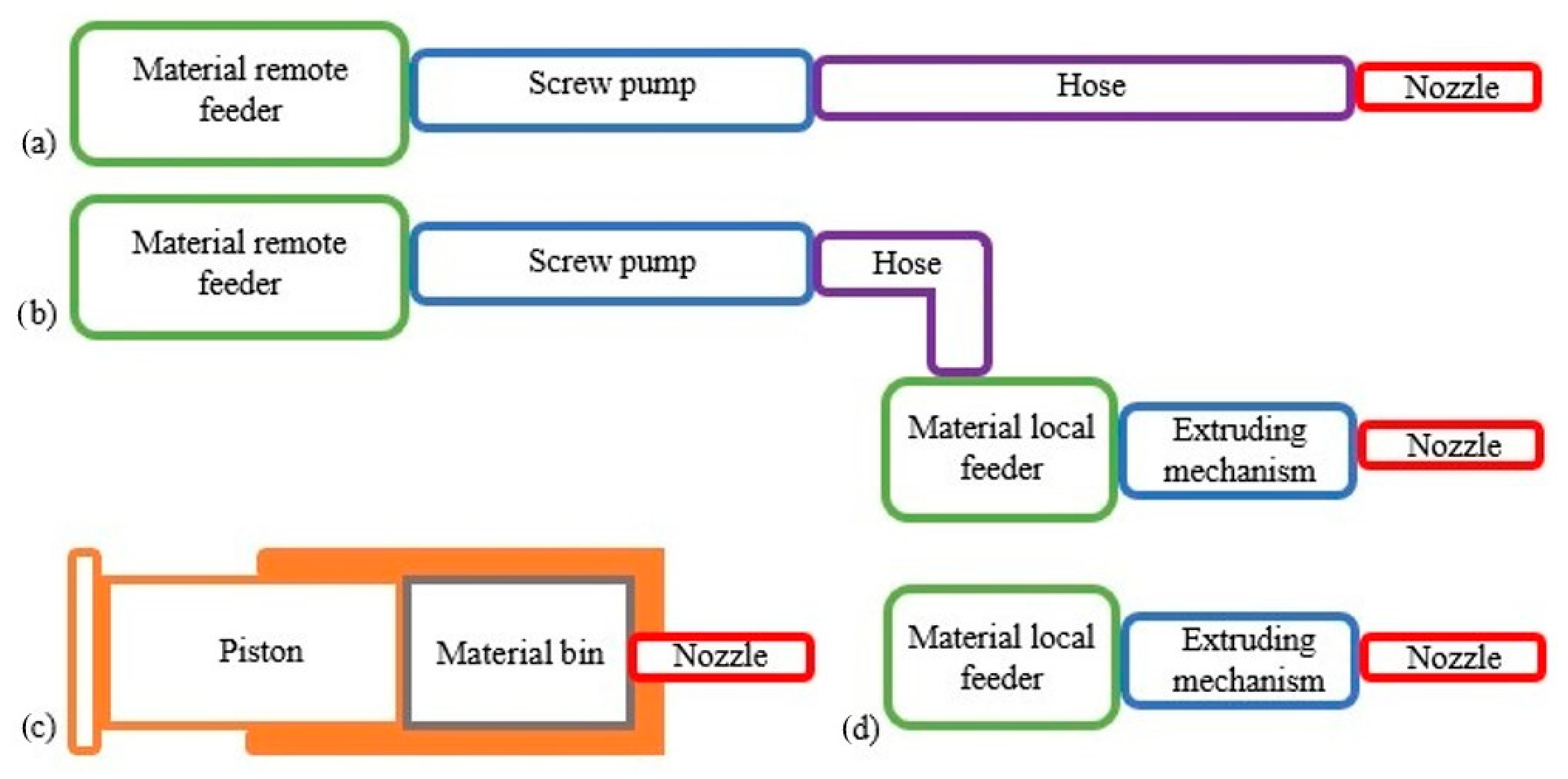
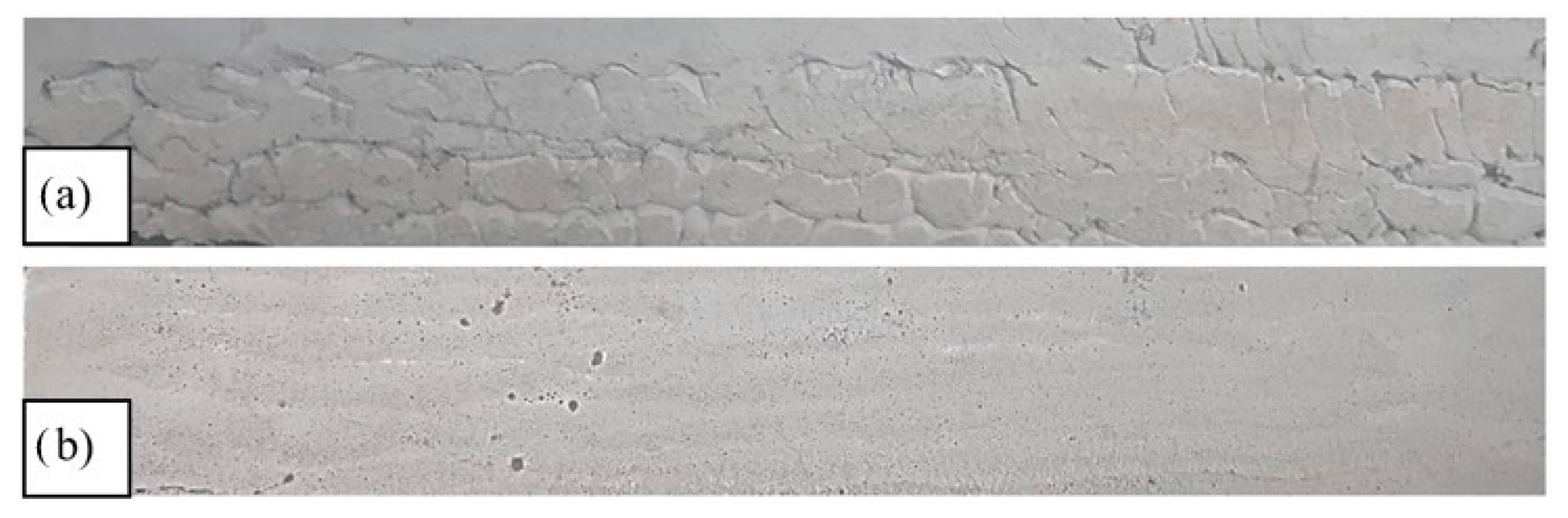
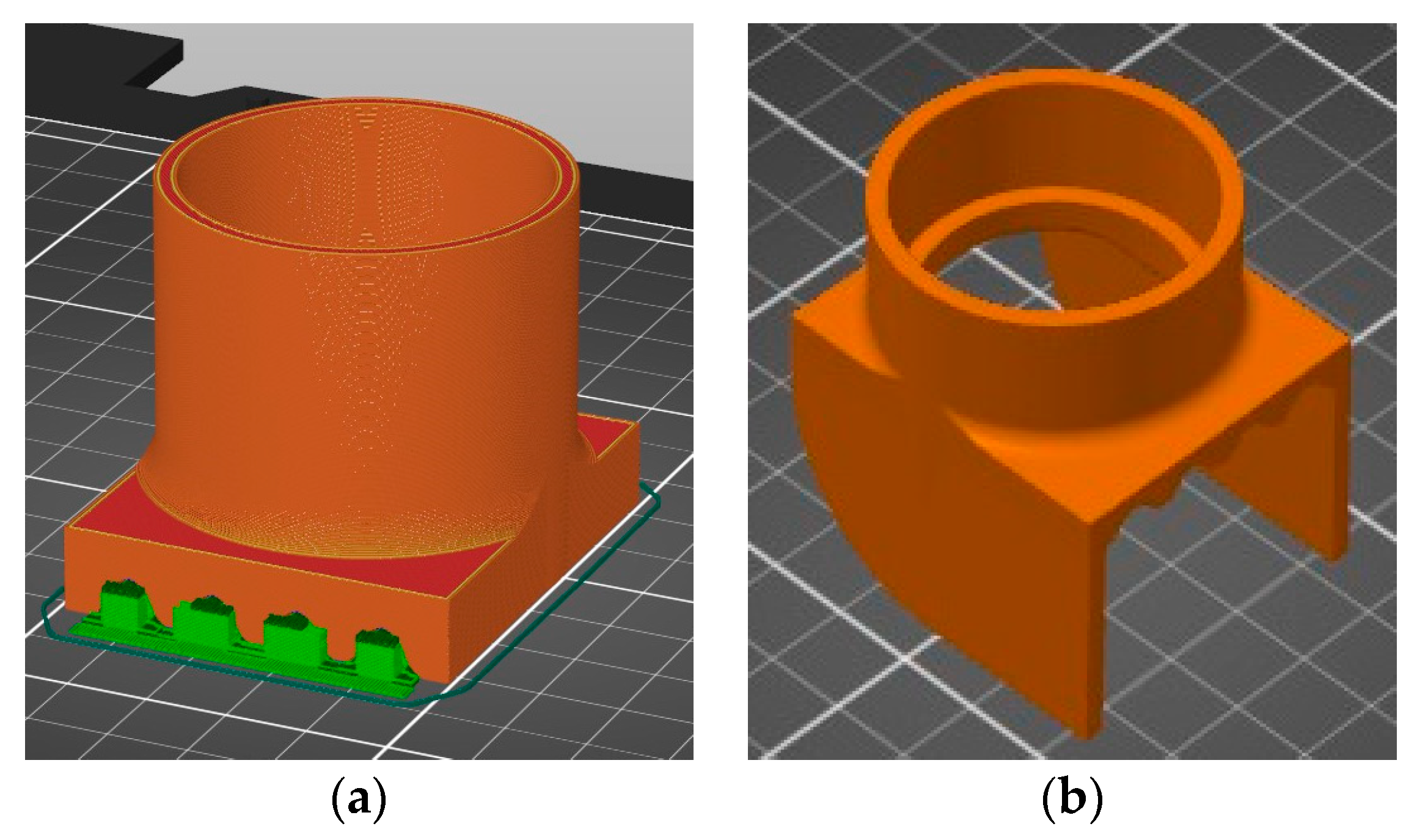
3. Extrudability
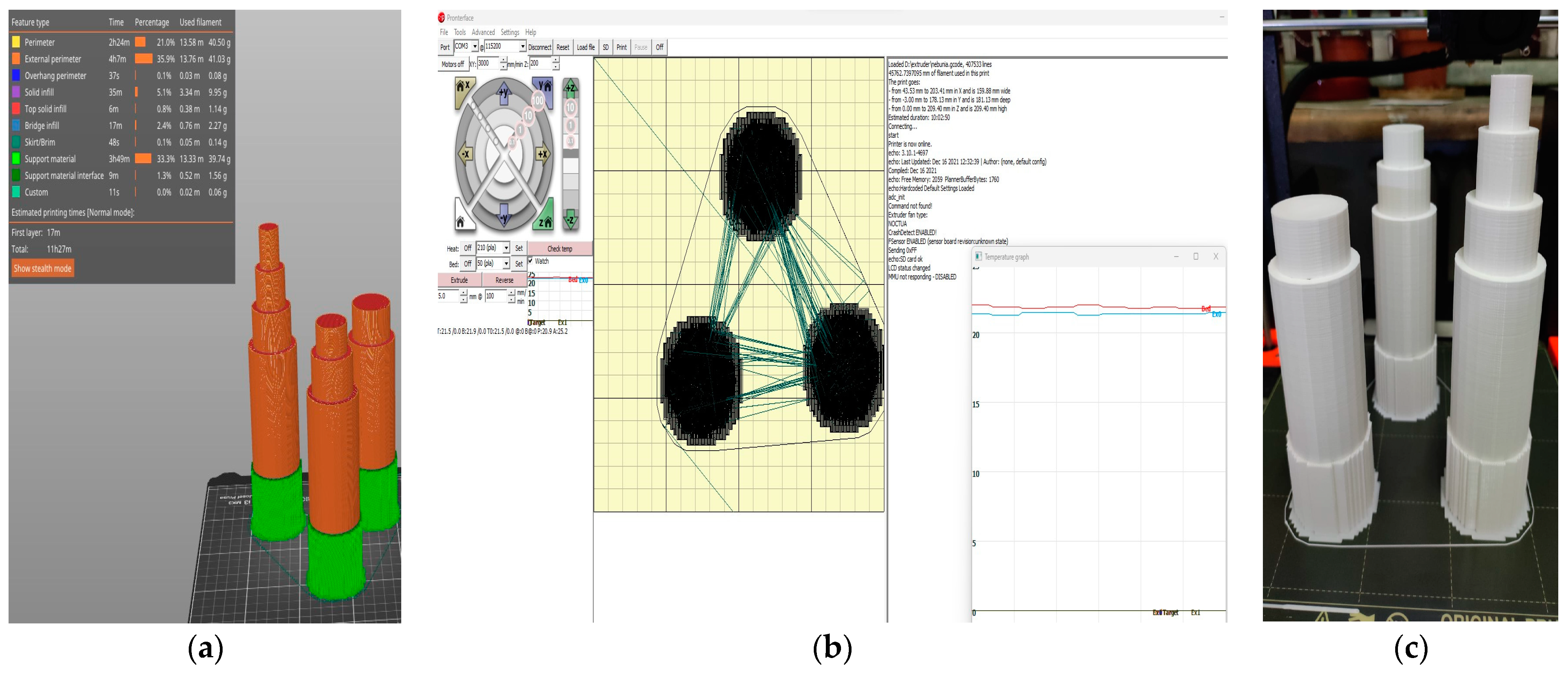
4. Buildability
5. Flowability
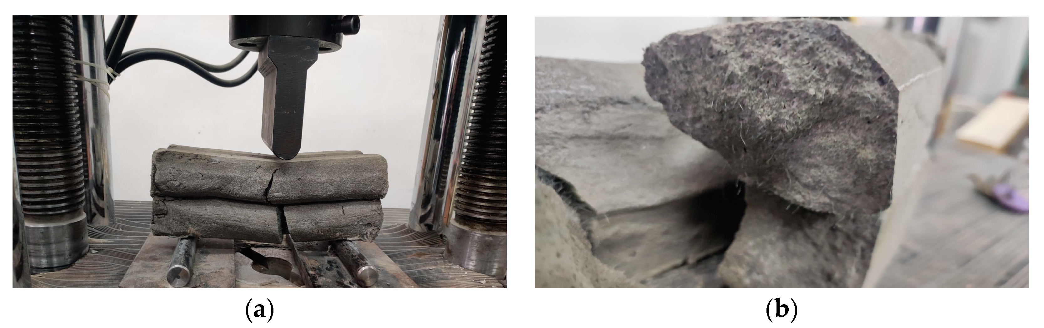
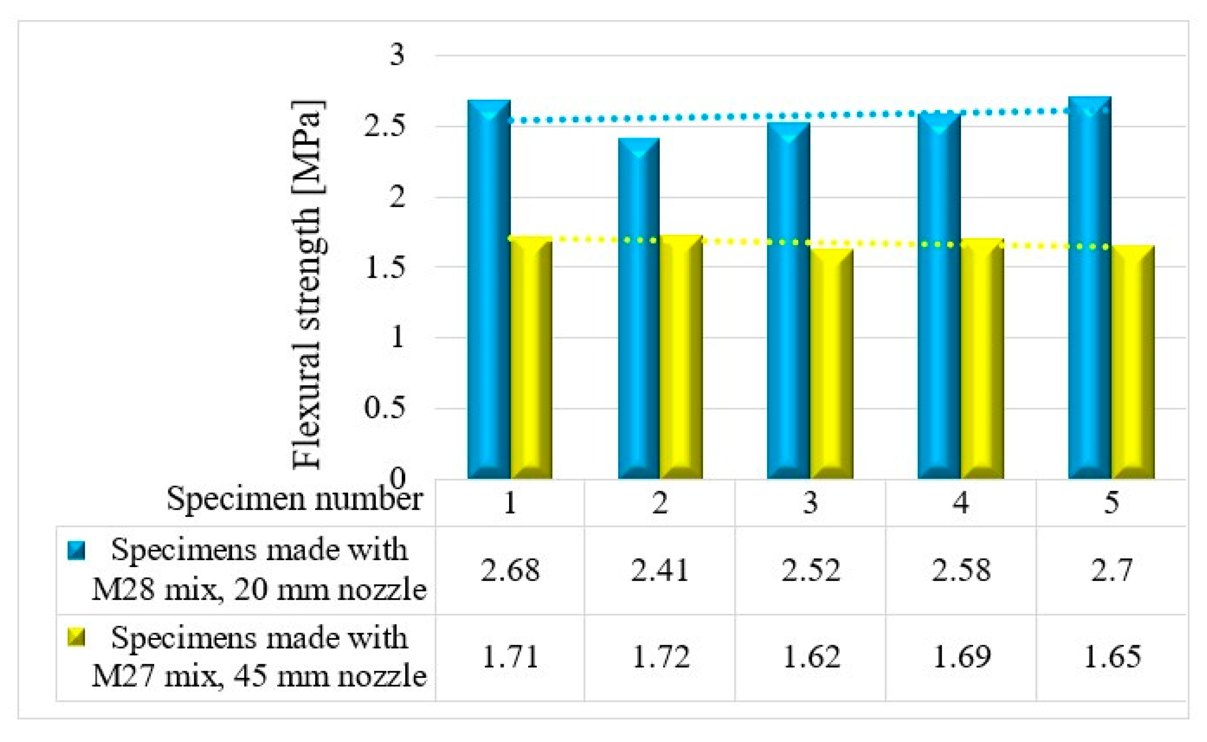
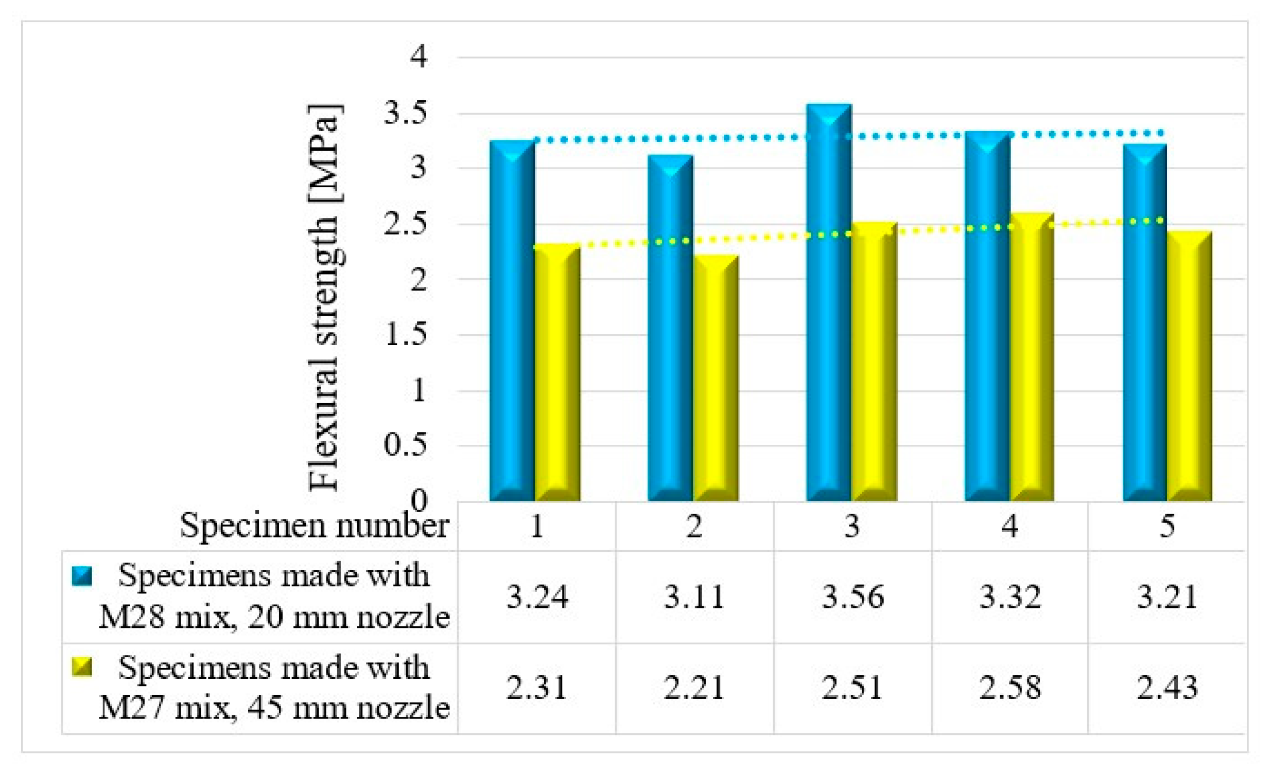
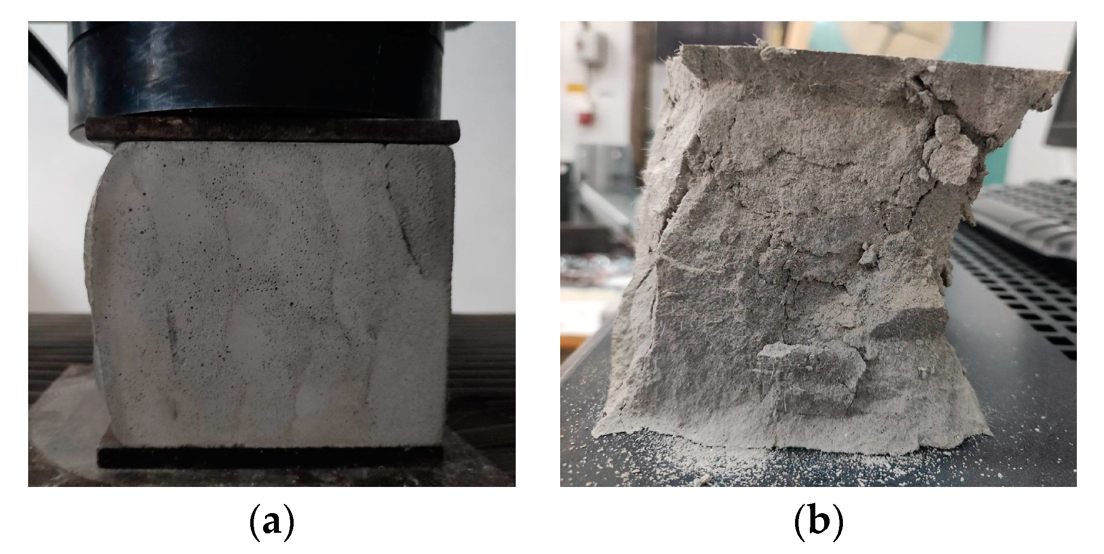
6. Flexural Strength
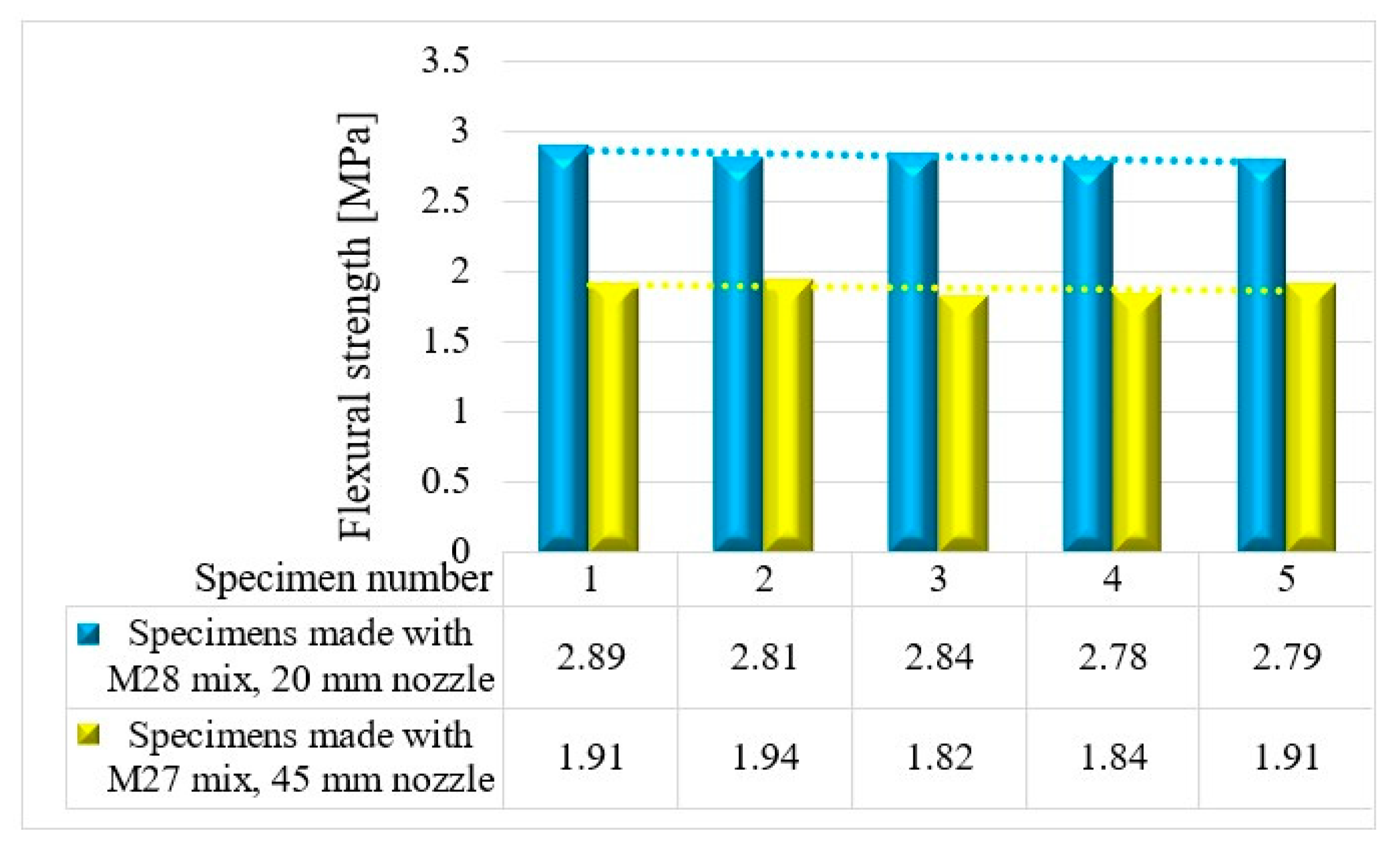
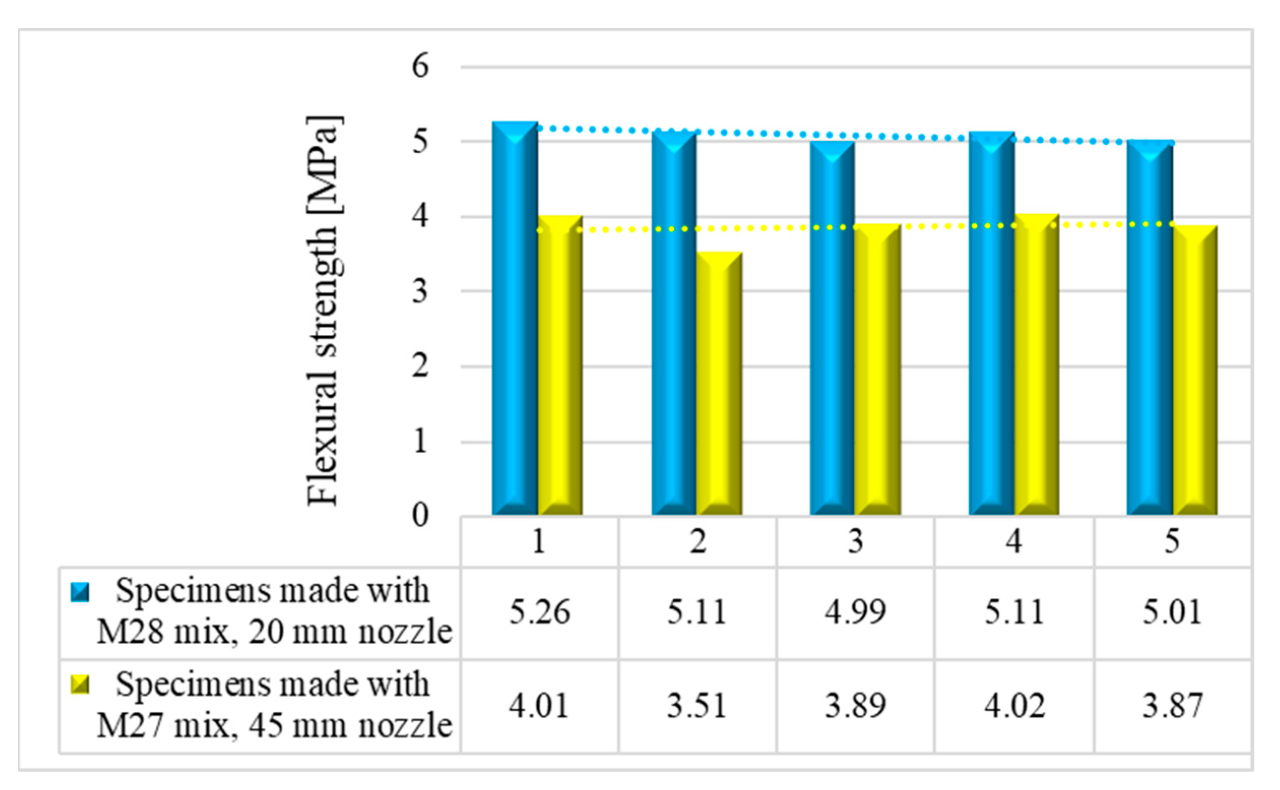
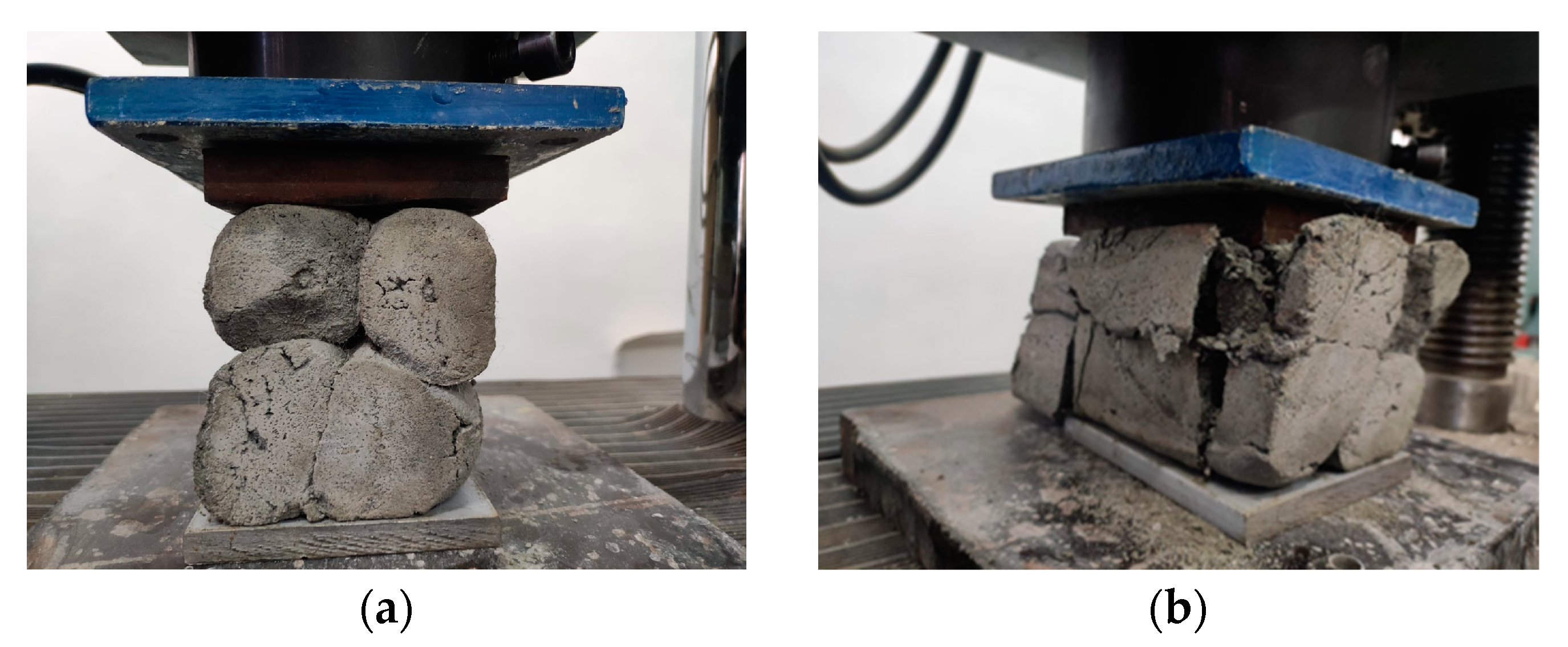
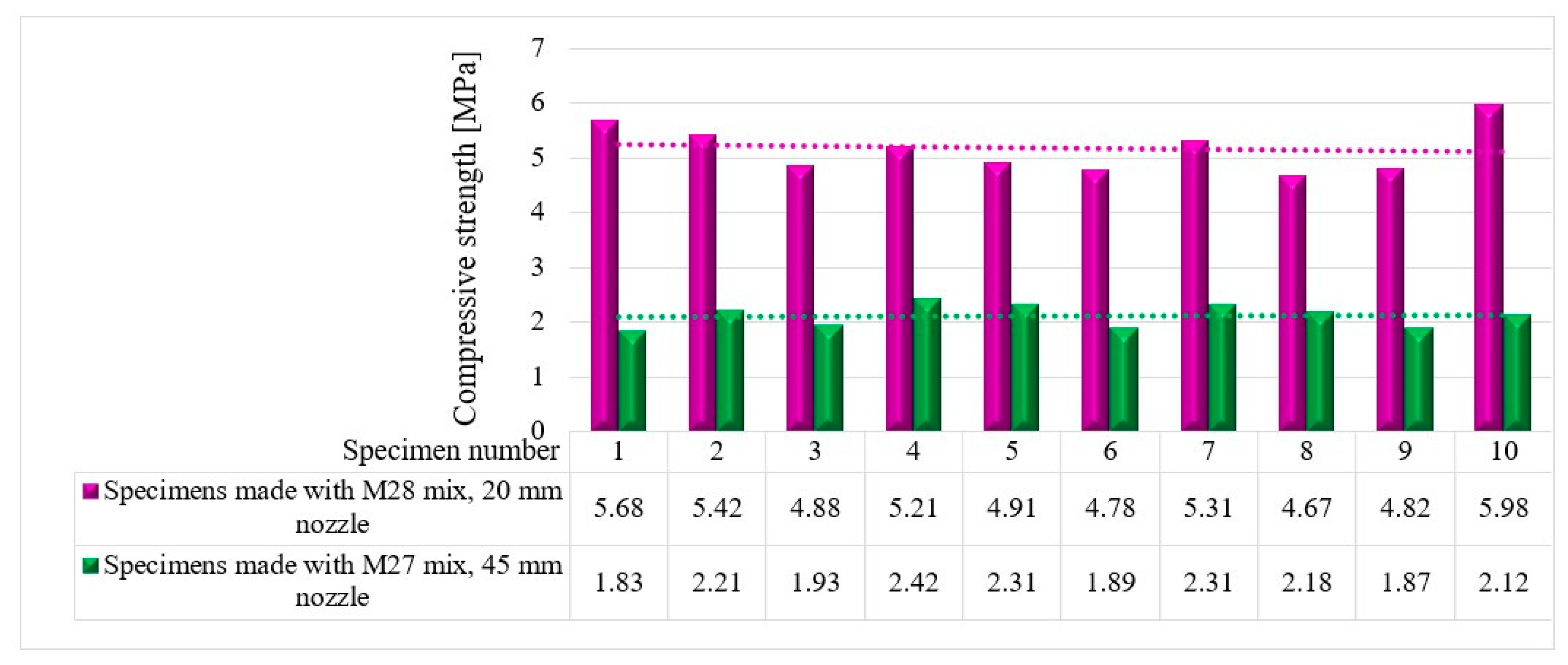
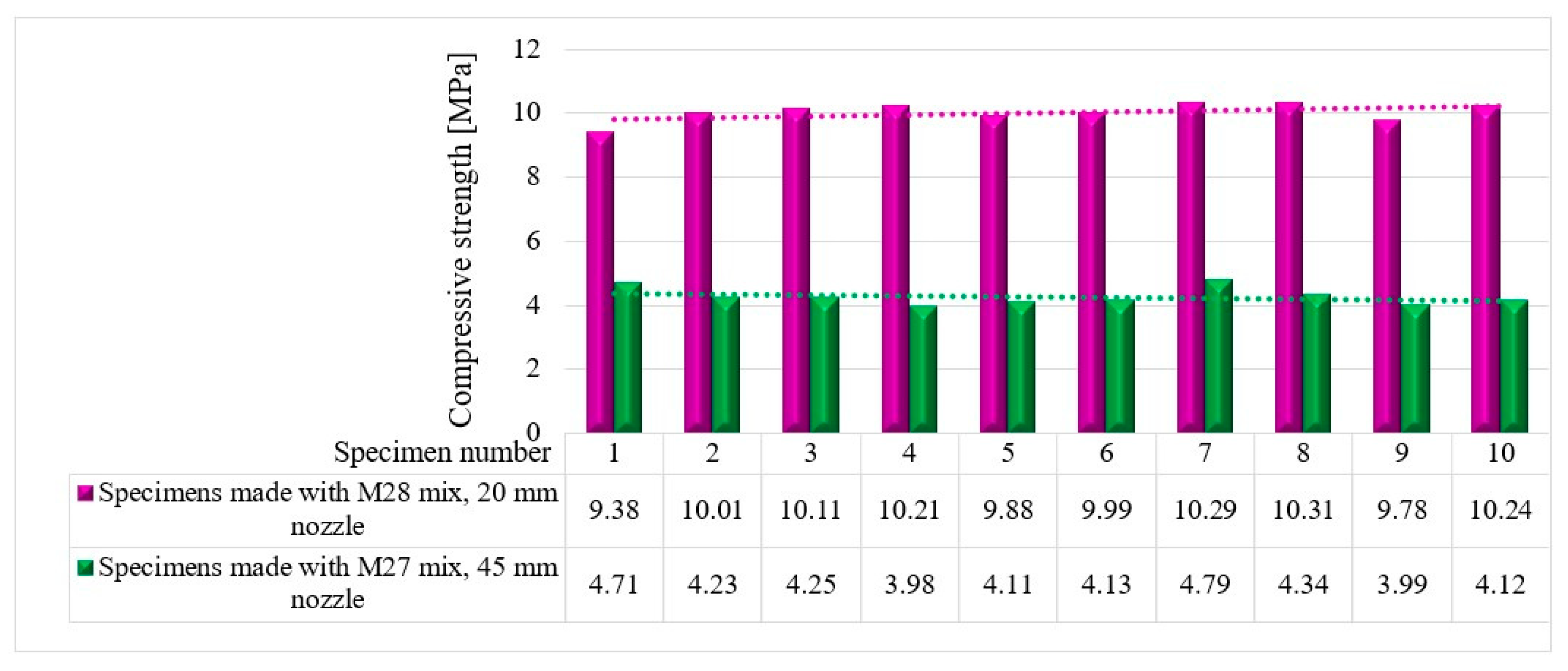
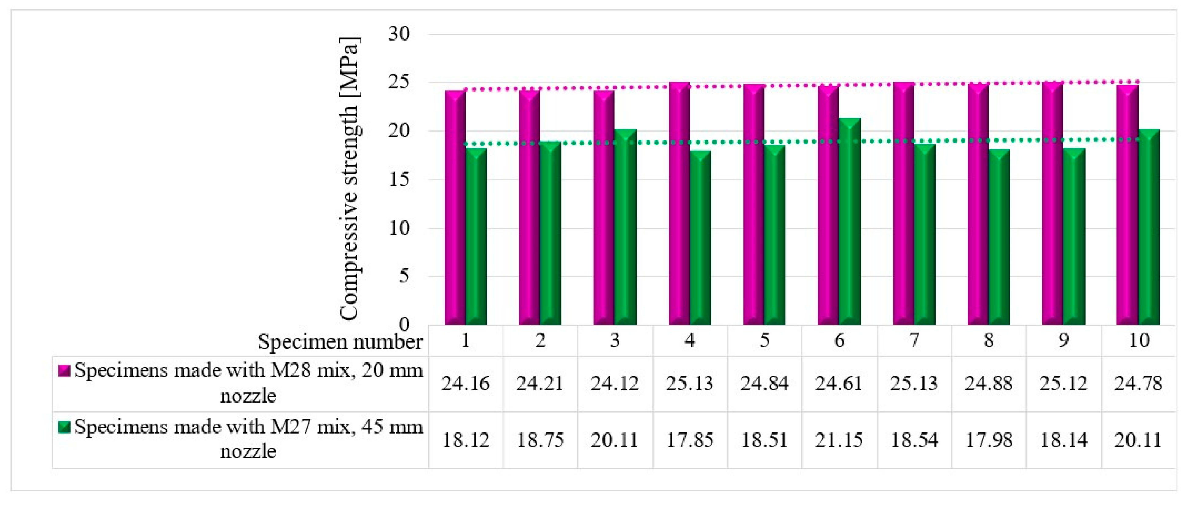
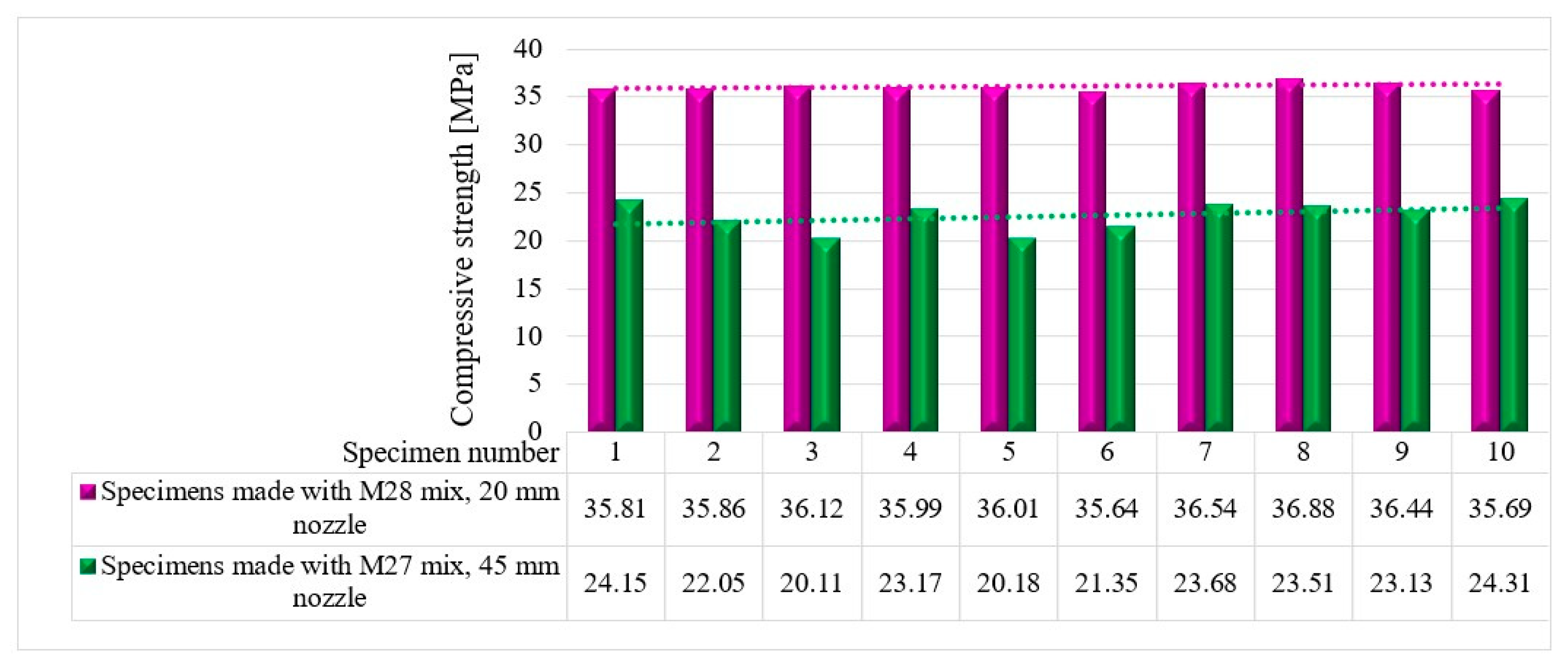
7. Compressive Strength
8. Discussion
9. Conclusions and Future Research Directions
- The M27 and M28 mixes have the most favorable fresh properties for 3D printing.
- Mixtures with lower stiffness exhibit improved flow characteristics, enabling consistent and uninterrupted material extrusion through the printing nozzle. Conversely, mixtures with excessive viscosity, such as those encountered in mixes M1-M16, pose significant challenges during the printing process. The high viscosity impedes the flow of the mortar material, making it prone to clogging within the printing nozzle. This clogging phenomenon disrupts the extrusion process, resulting in irregular material flow, the incomplete filling of printed layers, and a compromised structural integrity of the final printed components.
- In the case of mixes M27 and M28, the high buildability observed enabled the printing of multiple layers without any visible signs of instability or structural failure. This indicates that these mixtures possessed the necessary strength, viscosity, and bonding properties to sustain the progressive addition of layers and ensure the overall stability of the printed projects. The rest of the mixtures lacked the necessary strength, viscosity control, or bonding properties, leading to the progressive loss of stability or sudden plastic failure of the printed projects. As a result, the printed structures collapsed either gradually due to inadequate interlayer adhesion or suddenly due to an inability to bear the weight of the upper layers.
- Flowability within a range from 40 to 60 mm promotes the achievement of robust and structurally sound 3D-printed mortar structures. Mortar mixtures with lower flowability can result in inadequate compaction and compromised mechanical properties, while excessively high flowability may lead to reduced cohesion and interparticle interactions, thereby compromising the strength and durability of the printed components.
- The recommended slump flow range from 140 to 160 mm ensures favorable material flow behavior during 3D printing. Mixtures with slump flow values within this range exhibit appropriate viscosity and yield stress, facilitating consistent material flow through the printer nozzle. Slump flow values below 140 mm indicate a higher yield stress, making it challenging for the mortar to flow smoothly. On the other hand, slump flow values above 160 mm suggest excessive fluidity, increasing the risk of material spreading and the loss of structural stability during printing.
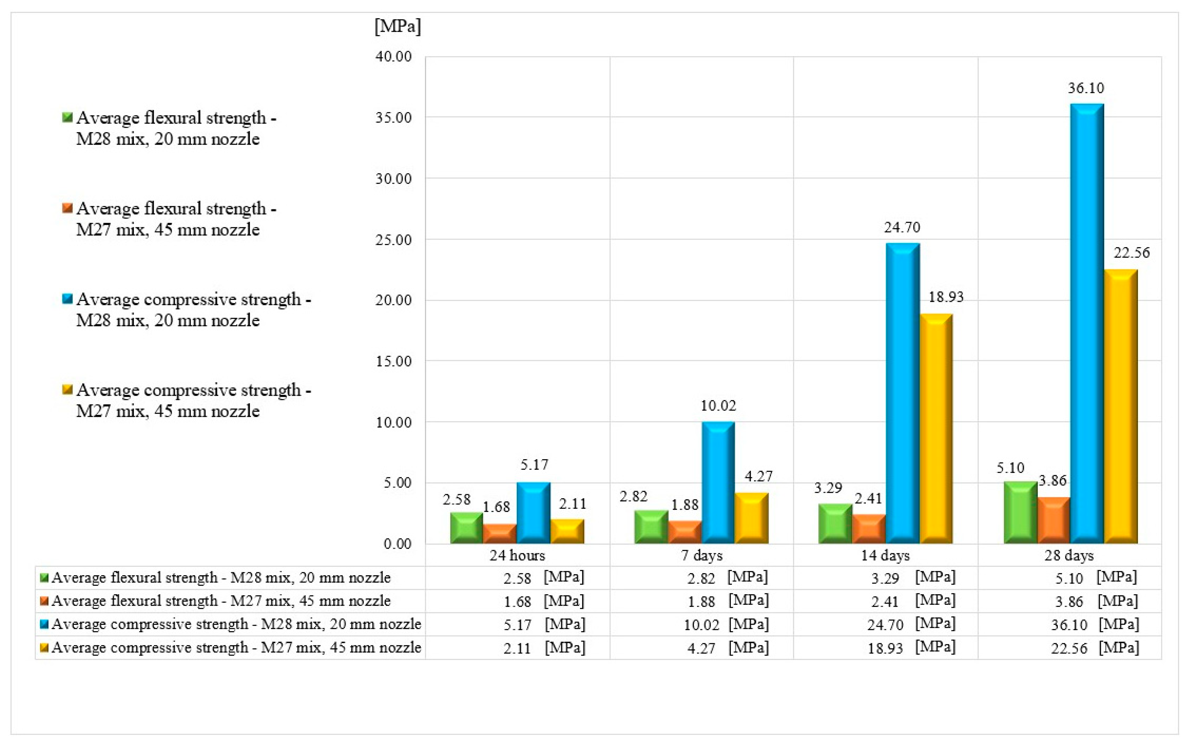
- The mechanical performance tests indicated that the 3D-printed specimens made with the M28 mix and printed through the 20 mm nozzle have considerably higher strengths than the ones made with the M27 mix and 45 mm nozzle. The improved strength of the mortar mixtures printed with narrow nozzles can be attributed to two primary mechanisms. Firstly, the reduced eccentricities minimize the formation of voids and weak spots within the printed layers, leading to improved structural integrity. Secondly, the enhanced exterior roundness achieved through the use of narrow nozzles ensures a more uniform distribution of forces during compression, resulting in higher strength values.
- Overall, this study presents a promising approach to 3D printing fiber-reinforced mortar without extrusion, and the results highlight the potential of using this technology for constructing complex structures with high strength and durability. The future research on this topic could lead to significant advances in the field of construction and infrastructure development. Also, the reduced facility requirements in this approach allow 3D printing to be made more available for civil engineering applications.
Author Contributions
Funding
Institutional Review Board Statement
Informed Consent Statement
Data Availability Statement
Acknowledgments
Conflicts of Interest
References
- Alami, A.H.; Olabi, A.G.; Ayoub, M.; Aljaghoub, H.; Alasad, S.; Abdelkareem, M.A. 3D Concrete Printing: Recent Progress, Applications, Challenges, and Role in Achieving Sustainable Development Goals. Buildings 2023, 13, 924. [Google Scholar] [CrossRef]
- Jin, Y.; Gao, C. Hybrid Optimization of Green Supply Chain Network and Scheduling in Distributed 3D Printing Intelligent Factory. Sustainability 2023, 15, 5948. [Google Scholar] [CrossRef]
- Lam, E.H.Y.; Yu, F.; Zhu, S.; Wang, Z. 3D Bioprinting for Next-Generation Personalized Medicine. Int. J. Mol. Sci. 2023, 24, 6357. [Google Scholar] [CrossRef]
- Al-Tamimi, A.K.; Alqamish, H.H.; Khaldoune, A.; Alhaidary, H.; Shirvanimoghaddam, K. Framework of 3D Concrete Printing Potential and Challenges. Buildings 2023, 13, 827. [Google Scholar] [CrossRef]
- Fonseca, M.; Matos, A.M. 3D Construction Printing Standing for Sustainability and Circularity: Material-Level Opportunities. Materials 2023, 16, 2458. [Google Scholar] [CrossRef] [PubMed]
- Quah, T.K.N.; Tay, Y.W.D.; Lim, J.H.; Tan, M.J.; Wong, T.N.; Li, K.H.H. Concrete 3D Printing: Process Parameters for Process Control, Monitoring and Diagnosis in Automation and Construction. Mathematics 2023, 11, 1499. [Google Scholar] [CrossRef]
- Mendřický, R.; Keller, P. Analysis of Object Deformations Printed by Extrusion of Concrete Mixtures Using 3D Scanning. Buildings 2023, 13, 191. [Google Scholar] [CrossRef]
- Dams, B.; Chen, B.; Shepherd, P.; Ball, R.J. Development of Cementitious Mortars for Aerial Additive Manufacturing. Appl. Sci. 2023, 13, 641. [Google Scholar] [CrossRef]
- Bello, N.D.; Memari, A.M. Comparative Review of the Technology and Case Studies of 3D Concrete Printing of Buildings by Several Companies. Buildings 2022, 13, 106. [Google Scholar] [CrossRef]
- García-Alvarado, R.; Moroni-Orellana, G.; Banda, P. Development of Variable Residential Buildings with 3D-Printed Walls. Buildings 2022, 12, 1796. [Google Scholar] [CrossRef]
- Ibrahim, I.; Eltarabishi, F.; Abdalla, H.; Abdallah, M. 3D Printing in Sustainable Buildings: Systematic Review and Applications in the United Arab Emirates. Buildings 2022, 12, 1703. [Google Scholar] [CrossRef]
- Salandin, A.; Quintana-Gallardo, A.; Gómez-Lozano, V.; Guillén-Guillamón, I. The First 3D-Printed Building in Spain: A Study on Its Acoustic, Thermal and Environmental Performance. Sustainability 2022, 14, 13204. [Google Scholar] [CrossRef]
- Korniejenko, K.; Łach, M. Geopolymers reinforced by short and long fibres—Innovative materials for additive manufacturing. Curr. Opin. Chem. Eng. 2020, 28, 167–172. [Google Scholar] [CrossRef]
- Mierzwiński, D.; Łach, M.; Gądek, S.; Lin, W.-T.; Tran, D.H.; Korniejenko, K. A brief overview of the use of additive manufacturing of con-create materials in construction. Acta Innov. 2023, 48, 22–37. [Google Scholar] [CrossRef]
- Chen, M.; Li, L.; Zheng, Y.; Zhao, P.; Lu, L.; Cheng, X. Rheological and mechanical properties of admixtures modified 3D printing sulphoaluminate cementitious materials. Constr. Build. Mater. 2018, 189, 601–611. [Google Scholar] [CrossRef]
- Al-Noaimat, Y.A.; Ghaffar, S.H.; Chougan, M.; Al-Kheetan, M.J. A review of 3D printing low-carbon concrete with one-part geopolymer: Engineering, environmental and economic feasibility. Case Stud. Constr. Mater. 2023, 18, e01818. [Google Scholar] [CrossRef]
- Hou, S.; Xiao, J.; Duan, Z.; Ma, G. Fresh properties of 3D printed mortar with recycled powder. Constr. Build. Mater. 2021, 309, 125186. [Google Scholar] [CrossRef]
- Roussel, N. Rheological requirements for printable concretes. Cem. Concr. Res. 2018, 112, 76–85. [Google Scholar] [CrossRef]
- Jiao, D.; De Schryver, R.; Shi, C.; De Schutter, G. Thixotropic structural build-up of cement-based materials: A state-of-the-art review. Cem. Concr. Compos. 2021, 122, 104152. [Google Scholar] [CrossRef]
- Boddepalli, U.; Panda, B.; Ranjani Gandhi, I.S. Rheology and printability of Portland cement based materials: A review. J. Sustain. Cem. Mater. 2022, 12, 789–807. [Google Scholar] [CrossRef]
- Wang, J.; Xie, Y.; Zhong, X.; Li, L. Test and simulation of cement hydration degree for shotcrete with alkaline and alkali-free accelerators. Cem. Concr. Compos. 2020, 112, 103684. [Google Scholar] [CrossRef]
- Lee, Y.S.; Lim, D.S.; Chun, B.S.; Ryou, J.S. Characterization of a sodium aluminate(NaAlO2)-based accelerator made via a tablet processing method. J. Ceram. Process. Res. 2013, 14, 87–91. [Google Scholar]
- Renan, P.S.; Sergio, H.P.C.; Renata, M.; Antonio, D.F. Relation between chemical processes and mechanical properties of sprayed cementitious matrices with accelerators. Cem. Concr. Compos. 2017, 79, 117–132. [Google Scholar]
- Su, Y.; Luo, B.; Luo, Z.; Huang, H.; Li, J.; Wang, D. Effect of Accelerators on the Workability, Strength, and Microstructure of Ultra-High-Performance Concrete. Materials 2022, 15, 159. [Google Scholar] [CrossRef]
- On the Development of Fly Ash-Based Geopolymer Concrete. ACI Mater. J. 2004, 111, 467–472. [CrossRef]
- Hardjito, D.; Rangan, B.V. Development and properties of low-calcium fly ash-based geopolymer concrete. Res. Rep. GC 2005. Available online: https://www.geopolymer.org/wp-content/uploads/curtin-flyash-GP-concrete-report.pdf (accessed on 5 April 2023).
- Luukkonen, T.; Abdollahnejad, Z.; Yliniemi, J.; Kinnunen, P.; Illikainen, M. One-part alkali-activated materials: A review. Cem. Concr. Res. 2018, 103, 21–34. [Google Scholar] [CrossRef]
- Luukkonen, T.; Abdollahnejad, Z.; Yliniemi, J.; Kinnunen, P.; Illikainen, M. Comparison of alkali and silica sources in one-part alkali-activated blast furnace slag mortar. J. Clean. Prod. 2018, 187, 171–179. [Google Scholar] [CrossRef]
- Kaze, R.C.; Naghizadeh, A.; Tchadjie, L.; Adesina, A.; Djobo, J.N.Y.; Nemaleu, J.G.D.; Kamseu, E.; Melo, U.C.; Tayeh, B.A. Lateritic soils based geopolymer materials: A review. Constr. Build. Mater. 2022, 344, 128157. [Google Scholar] [CrossRef]
- Su, Y.; Luo, B.; Luo, Z.; Xu, F.; Huang, H.; Long, Z.; Shen, C. Mechanical characteristics and solidification mechanism of slag/fly ash-based geopolymer and cement solidified organic clay: A comparative study. J. Build. Eng. 2023, 71, 106459. [Google Scholar] [CrossRef]
- Cao, X.; Yu, S.; Cui, H.; Li, Z. 3D Printing Devices and Reinforcing Techniques for Extruded Cement-Based Materials: A Review. Buildings 2022, 12, 453. [Google Scholar] [CrossRef]
- Asprone, D.; Auricchio, F.; Menna, C.; Mercuri, V. 3D printing of reinforced concrete elements: Technology and design approach. Constr. Build. Mater. 2018, 165, 218–231. [Google Scholar] [CrossRef]
- Katzer, J.; Szatkiewicz, T. Properties of concrete elements with 3-D printed formworks which substitute steel reinforcement. Constr. Build. Mater. 2019, 210, 157–161. [Google Scholar] [CrossRef]
- Salazar, B.; Aghdasi, P.; Williams, I.D.; Ostertag, C.P.; Taylor, H.K. Polymer lattice-reinforcement for enhancing ductility of concrete. Mater. Des. 2020, 196, 109184. [Google Scholar] [CrossRef]
- Xu, Y.; Šavija, B. Development of strain hardening cementitious composite (SHCC) reinforced with 3D printed polymeric reinforcement: Mechanical properties. Compos. Part B Eng. 2019, 174, 107011. [Google Scholar] [CrossRef]
- Volpe, S.; Sangiorgio, V.; Petrella, A.; Coppola, A.; Notarnicola, M.; Fiorito, F. Building Envelope Prefabricated with 3D Printing Technology. Sustainability 2021, 13, 8923. [Google Scholar] [CrossRef]
- Sanjayan, J.G.; Nematollahi, B.; Xia, M.; Marchment, T. Effect of surface moisture on inter-layer strength of 3D printed concrete. Constr. Build. Mater. 2018, 172, 468–475. [Google Scholar] [CrossRef]
- Van Der Putten, J.; Deprez, M.; Cnudde, V.; De Schutter, G.; Van Tittelboom, K. Microstructural Characterization of 3D Printed Cementitious Materials. Materials 2019, 12, 2993. [Google Scholar] [CrossRef] [PubMed] [Green Version]
- Van Der Putten, J.; De Schutter, G.; Van Tittelboom, K. Surface modification as a technique to improve inter-layer bonding strength in 3D printed cementitious materials. RILEM Tech. Lett. 2019, 4, 33–38. [Google Scholar] [CrossRef] [Green Version]
- Li, Z.; Wang, L.; Ma, G. Mechanical improvement of continuous steel microcable reinforced geopolymer composites for 3D printing subjected to different loading conditions. Compos. Part B Eng. 2020, 187, 107796. [Google Scholar] [CrossRef]
- Hambach, M.; Volkmer, D. Properties of 3D-printed fiber-reinforced Portland cement paste. Cem. Concr. Compos. 2017, 79, 62–70. [Google Scholar] [CrossRef]
- Pietras, D.; Zbyszyński, W.; Sadowski, T. A 3D Printing Method of Cement-Based FGM Composites Containing Granulated Cork, Polypropylene Fibres, and a Polyethylene Net Interlayer. Materials 2023, 16, 4235. [Google Scholar] [CrossRef]
- Ogura, H.; Nerella, V.N.; Mechtcherine, V. Developing and Testing of Strain-Hardening Cement-Based Composites (SHCC) in the Context of 3D-Printing. Materials 2018, 11, 1375. [Google Scholar] [CrossRef] [PubMed] [Green Version]
- Farina, I.; Fabbrocino, F.; Carpentieri, G.; Modano, M.; Amendola, A.; Goodall, R.; Feo, L.; Fraternali, F. On the reinforcement of cement mortars through 3D printed polymeric and metallic fibers. Compos. Part B Eng. 2016, 90, 76–85. [Google Scholar] [CrossRef]
- Baz, B.; Aouad, G.; Leblond, P.; Al-Mansouri, O.; D’Hondt, M.; Remond, S. Mechanical assessment of concrete—Steel bonding in 3D printed elements. Constr. Build. Mater. 2020, 256, 119457. [Google Scholar] [CrossRef]
- Baz, B.; Aouad, G.; Remond, S. Effect of the printing method and mortar’s workability on pull-out strength of 3D printed elements. Constr. Build. Mater. 2019, 230, 117002. [Google Scholar] [CrossRef]
- Bester, F.; Heever, M.V.D.; Kruger, J.; Cho, S.; van Zijl, G. Steel Fiber Links in 3D Printed Concrete; Springer: Cham, The Netherlands, 2020; pp. 398–406. [Google Scholar]
- Wang, L.; Ma, G.; Liu, T.; Buswell, R.; Li, Z. Interlayer reinforcement of 3D printed concrete by the in-process deposition of U-nails. Cem. Concr. Res. 2021, 148, 106535. [Google Scholar] [CrossRef]
- Liu, M.; Zhang, Q.; Tan, Z.; Wang, L.; Li, Z.; Ma, G. Investigation of steel wire mesh reinforcement method for 3D concreteprinting. Arch. Civ. Mech. Eng. 2021, 21, 34. [Google Scholar] [CrossRef]
- Matthäus, C.; Kofler, N.; Kränkel, T.; Weger, D.; Gehlen, C. Interlayer Reinforcement Combined with Fiber Reinforcement for Extruded Lightweight Mortar Elements. Materials 2020, 13, 4778. [Google Scholar] [CrossRef]
- Sun, X.; Gao, C.; Wang, H. Bond performance between BFRP bars and 3D printed concrete. Constr. Build. Mater. 2020, 269, 121325. [Google Scholar] [CrossRef]
- CP 012-1-2007; Cod Pentru Producerea Betonului. Emitent Ministerul Dezvoltării Regionale și Administrației Publice—MDRAP: Bucharest, Romania, 2007. (In Romanian)
- NE 013—2002; Cod de Practică Pentru Execuţia Elementelor Prefabricatelor Din Beton, Beton Armat şi Beton Precomprimat. Emitent Ministerul Dezvoltării Regionale și Administrației Publice—MDRAP: Bucharest, Romania, 2002. (In Romanian)
- GP 075:2002; Ghid Pentru Stabilirea Criteriilor de Performanță a Compozițiilor Pentru Betoane Armate Dispers cu Fibre Metalice. Emitent Ministerul Dezvoltării Regionale și Administrației Publice—MDRAP: Bucharest, Romania, 2002. (In Romanian)
- ATE 004-07/1707-2022; Procedeu de Execuție a Îmbrăcăminților Rutiere Din Beton de Ciment. Emitent Ministerul Dezvoltării Regionale și Administrației Publice—MDRAP: Bucharest, Romania, 2022. (In Romanian)
- Available online: https://romfracht.com/ro/fibers/?gclid=Cj0KCQjwuLShBhC_ARIsAFod4fLouQv6ihOaNCAF9iAex2c8Y6g90XyG4GRtyNW6kr4-UBAN7HQFLjsaAgUgEALw_wcB (accessed on 5 April 2023).
- Available online: https://www.master-builders-solutions.com/ro-ro/products (accessed on 5 April 2023).
- Villacis, N.; Gualavisi, M.; Narvaez-Munoz, C.; Carrion, L.; Loza-Matovelle, D.; Naranjo, F. Additive manufacturing of a theological characterized cement-based composite material. In Proceedings of the 2017 European Conference on Electrical Engineering and Computer Science (EECS), Bern, Switzerland, 19 November 2017; pp. 326–331. [Google Scholar]
- Olivas, A.; Helsel, M.A.; Martys, N.; Ferraris, C.; George, W.L.; Ferron, R. Rheological Measurement of Suspensions without Slippage: Experiment and Model; National Institute of Standards and Technology: Gaithersburg, MA, USA, 2016.
- Panda, B.; Singh, G.B.; Unluer, C.; Tan, M.J. Synthesis and characterization of one-part geopolymers for extrusion based 3D concrete printing. J. Clean. Prod. 2019, 220, 610–619. [Google Scholar] [CrossRef]
- Nair, S.A.; Panda, S.; Santhanam, M.; Sant, G.; Neithalath, N. A critical examination of the influence of material characteristics and extruder geometry on 3D printing of cementitious binders. Cem. Concr. Compos. 2020, 112, 103671. [Google Scholar] [CrossRef]
- Lim, J.H.; Weng, Y.; Pham, Q.-C. 3D printing of curved concrete surfaces using Adaptable Membrane Formwork. Constr. Build. Mater. 2019, 232, 117075. [Google Scholar] [CrossRef]
- Xu, J.; Ding, L.; Cai, L.; Zhang, L.; Luo, H.; Qin, W. Volume-forming 3D concrete printing using a variable-size square nozzle. Autom. Constr. 2019, 104, 95–106. [Google Scholar] [CrossRef]
- Ma, G.; Li, Z.; Wang, L.; Wang, F.; Sanjayan, J. Mechanical anisotropy of aligned fiber reinforced composite for extrusion-based 3D printing. Constr. Build. Mater. 2019, 202, 770–783. [Google Scholar] [CrossRef]
- Available online: https://www.prusa3d.com/category/original-prusa-i3-mk3s/?gclid=Cj0KCQjwuLShBhC_ARIsAFod4fIvQM2FeRdV7ojyFYXp7TWApkmqjEaw99pJnRBwk-gt0BsYoD4QKl4aApexEALw_wcB (accessed on 5 April 2023).
- Available online: https://www.pronterface.com/ (accessed on 5 April 2023).
- Zhang, C.; Nerella, V.N.; Krishna, A.; Wang, S.; Zhang, Y.; Mechtcherine, V.; Banthia, N. Mix design concepts for 3D printable concrete: A review. Cem. Concr. Compos. 2021, 122, 104155. [Google Scholar] [CrossRef]
- Ma, G.; Li, Z.; Wang, L. Printable properties of cementitious material containing copper tailings for extrusion based 3D printing. Constr. Build. Mater. 2018, 162, 613–627. [Google Scholar] [CrossRef]
- Bai, G.; Wang, L.; Ma, G.; Sanjayan, J.; Bai, M. 3D printing eco-friendly concrete containing under-utilized and waste solids as aggregates. Cem. Concr. Compos. 2021, 1, 104037. [Google Scholar] [CrossRef]
- EN 12350-2:2019; Testing Fresh Concrete—Part 2: Slump Test. European Committee for Standardization: Brussels, Belgium, 2019.
- Tay, Y.W.D.; Qian, Y.; Tan, M.J. Printability region for 3D concrete printing using slump and slump flow test. Compos.B Eng. 2019, 174, 106968. [Google Scholar] [CrossRef]
- Chen, Y.; Zhang, Y.; Pang, B.; Liu, Z.; Liu, G. Extrusion-based 3D printing concrete with coarse aggregate: Printability and direction-dependent mechanical performance. Constr. Build. Mater. 2021, 296, 123624. [Google Scholar] [CrossRef]
- SR EN 12390-5:2019; Încercare pe Beton Întărit. Partea 5: REZISTENȚA la Încovoiere a Epruvetelor. Organismul Național de Standardizare din România: Bucharest, Romania, 2019. (In Romanian)
- SR EN 12390-3:2002; Încercare pe Beton Întărit. Partea 3: Rezistenţa la Compresiune a Epruvetelor. Organismul Național de Standardizare din România: Bucharest, Romania, 2002. (In Romanian)
- Ungureanu, D.; Taranu, N.; Isopescu, D.N.; Lupasteanu, V.; Scutaru, M.C.; Hudisteanu, I. Failure particularities of adhesively bonded joints between pultruded GFRP composite profiles. IOP Conf. Ser. -Mater. Sci. Eng. 2018, 400, 032011. [Google Scholar] [CrossRef] [Green Version]
- Hudisteanu, I.; Taranu, N.; Isopescu, D.N.; Entuc, I.S.; Oprisan, G.; Ungureanu, D. Numerical analysis of intralaminar damage evolution on various composite laminates. IOP Conf. Ser. -Mater. Sci. Eng. 2018, 400, 042031. [Google Scholar] [CrossRef]
- Ungureanu, D.; Taranu, N.; Ghiga, D.A.; Isopescu, D.N.; Mihai, P.; Cozmanciuc, R. Diagonal Tensile Test on Masonry Panels Strengthened with Textile-Reinforced Mortar. Materials 2021, 14, 7021. [Google Scholar] [CrossRef]
- Lupasteanu, V.; Ungureanu, D.; Taranu, N.; Isopescu, D.N.; Lupasteanu, R.; Mihai, P. Structural Response of Bonded Joints between FRP Composite Strips and Steel Plates. Materials 2021, 14, 6722. [Google Scholar] [CrossRef] [PubMed]
- Oprisan, G.; Taranu, N.; Munteanu, V.; Budescu, M.; Cozmanciuc, C.; Oltean, R. Improvement of concrete strength through confining with composite membranes Romanian. J. Mater. 2011, 41, 302–315. [Google Scholar]
- Taranu, N.; Oprisan, G.; Entuc, I.; Budescu, M.; Munteanu, V.; Taranu, G. Composite and hybrid solutions for sustainable development in civil engineering. Environ. Eng. Manag. J. 2012, 11, 783–793. [Google Scholar] [CrossRef]
- Oprisan, G.; Taranu, N.; Budescu, M.; Entuc, I. Structural behaviour of reinforced concrete beams strengthened by CFRP plate bonding Romanian. J. Mater. 2012, 42, 387–398. [Google Scholar]


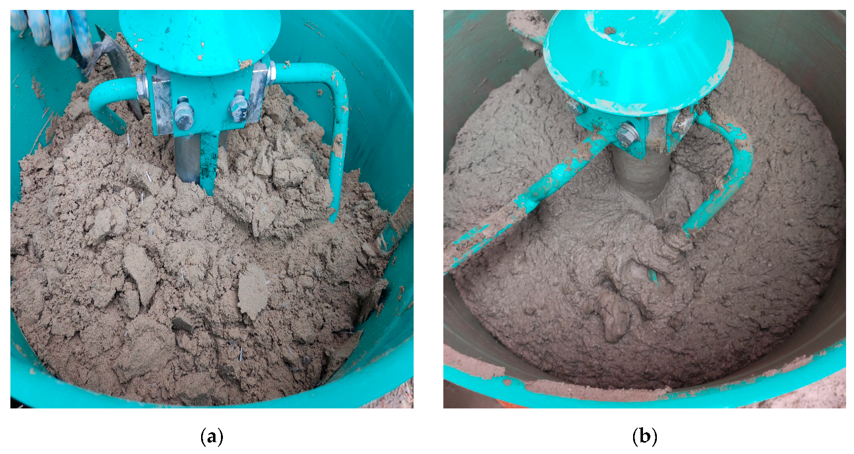
| Method 1 | Prepared in a Pan Mixer with Constant Speed |
|---|---|
| Step 1 | Weigh all materials. This step is common for all of the methods; thus, it is not repeated in the next sections of this table. |
| Step 2 | Mix the viscosity-modifying agent and the plasticizer in two separate glass containers with 1/3 water (calculated based on the agent’s mass) taken from the total water amount. This step is common for all of the methods; thus, it is not repeated in the next sections of this table. |
| Step 3 | Mix the sand, the limestone filler, and the polypropylene fibers for 5 min. |
| Step 4 | Add half of the water and mixing for 5 min. |
| Step 5 | Let mixture settle for 5 min. This step is common for all of the methods; thus, it is not repeated in the next sections of this table. |
| Step 6 | Add the cement and the rest of the water. Mix for 5 min. |
| Step 7 | Add the viscosity-modifying agent and the plasticizer. Mix for 5 min. |
| Method 2 | Prepared in a site concrete mixer with constant speed |
| Step 3 | Mix the sand, the limestone filler, and the polypropylene fibers for 5 min. Manually disperse the fibers before adding them. During the mixing time, keep the drum constantly tilted between 30° and 50°. |
| Step 4 | Add half of the water and mix for 5 min. During the mixing time, keep the drum constantly tilted between 30° and 50°. |
| Step 6 | Add the cement and the rest of the water. Mix for 5 min. |
| Step 7 | Add the viscosity-modifying agent and the plasticizer. Mix for 7 min. |
| Method 3 | Prepared in a cylindrical tank using a handheld electrical mortar mixer with adjustable speed |
| Step 3 | Mix the sand, the limestone filler, and the polypropylene fibers for 5 min. Gradually increase the speed up to 350 RPM. Use a cylindrical tank to avoid material trapping at corners. |
| Step 4 | Add half of the water and mix for 5 min at 500 RPM. |
| Step 6 | Add the cement and the rest of the water. Mix for 5 min at 700 RPM. |
| Step 7 | Add the viscosity-modifying agent and the plasticizer. Mix for 7 min at 700 RPM. |
| Mix | Sand (kg) | Cement (kg) | Limestone Filler (kg) | Fibers (kg) | Superplasticizer (%) | Viscosity Modifying Agent (%) | Water (L) | W/C |
|---|---|---|---|---|---|---|---|---|
| M1 | 1358 | 580 | 200 | 7 | 1.2 | 0.2 | 200 | 0.345 |
| Extrudability | The M1 mix could not be extruded. Blockage occurred in the pump feeder shaft. | |||||||
| M2 | 1358 | 580 | 200 | 5 | 1.2 | 0.2 | 200 | 0.345 |
| Extrudability | The M2 mix could not be extruded. Blockage occurred in the pump feeder shaft. | |||||||
| M3 | 1358 | 580 | 200 | 3 | 1.2 | 0.2 | 200 | 0.345 |
| Extrudability | The M3 mix could not be extruded. Blockage occurred either in the pump feeder shaft or in the outlet unit. | |||||||
| M4 | 1358 | 580 | 200 | 1 | 1.2 | 0.2 | 200 | 0.345 |
| Extrudability | The M4 mix could be extruded but blockages still occurred. Thus, the water quantity was gradually increased starting from a step of 5 l/m3. The final quantity of water (265 l) corresponded to the M17 mix. | |||||||
| M17 | 1358 | 580 | 200 | 1 | 1.2 | 0.2 | 265 | 0.457 |
| Extrudability | The M17 mix could be extruded without blockages. | |||||||
| Buildability | The M17 mixture could not be printed as large deformations occurred in the bottom layers. The mix was too fluid; the percentage of viscosity-modifying agent was increased by 0.1%. | |||||||
| M18 | 1358 | 580 | 200 | 1 | 1.2 | 0.3 | 265 | 0.457 |
| Extrudability | The M18 mix could be extruded without blockages. | |||||||
| Buildability | The M18 mixture could not be printed as large deformations occurred in the bottom layers. The mix was too fluid; the percentage of viscosity-modifying agent was increased by 0.1%. | |||||||
| M19 | 1358 | 580 | 200 | 1 | 1.2 | 0.4 | 265 | 0.457 |
| Extrudability | The M19 mix could be extruded without blockages. | |||||||
| Buildability | The M19 mixture could not be printed as large deformations still occurred in the bottom layers. The mix was too fluid; the percentage of viscosity-modifying agent was increased by 0.2%. | |||||||
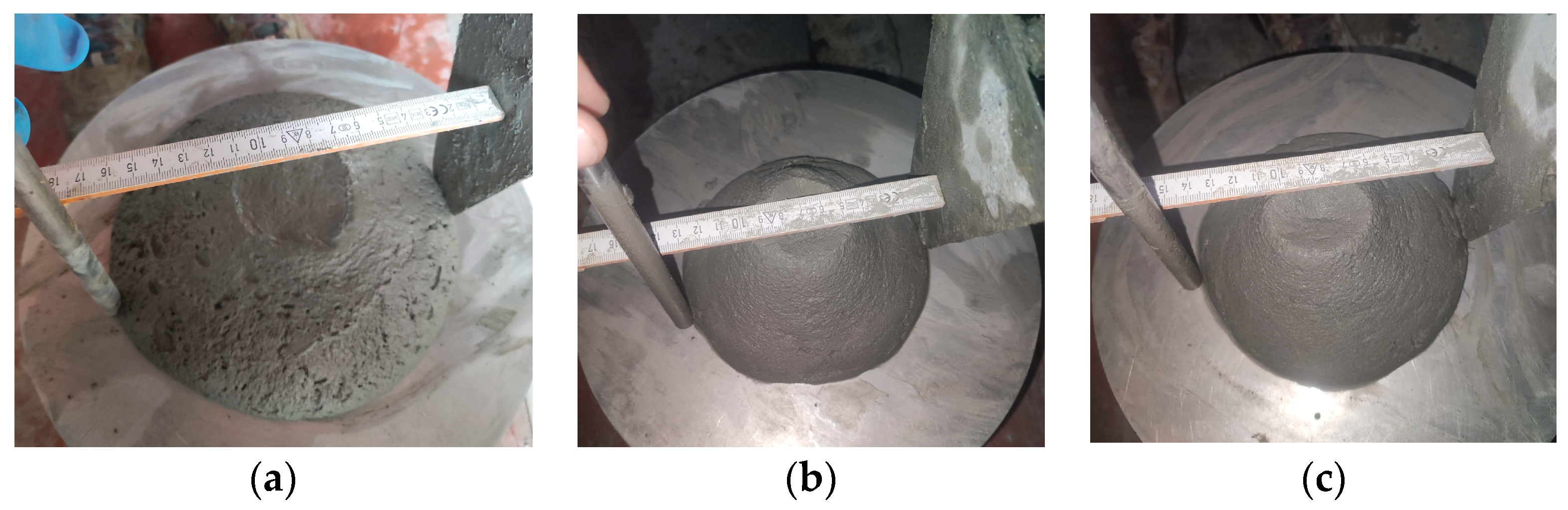
| Slump flow | 150 mm | |||||||
| M20 | 1358 | 580 | 200 | 1 | 1.2 | 0.6 | 265 | 0.457 |
| Extrudability | The M20 mix could be extruded without blockages. | |||||||
| Buildability | The M20 mixture could not be printed as large deformations still occurred in the bottom layers. The mix was too fluid; the percentage of viscosity-modifying agent was increased by 0.2%. | |||||||
| Slump flow | 140 mm | |||||||
| M21 | 1358 | 580 | 200 | 1 | 1.2 | 0.8 | 265 | 0.457 |
| Extrudability | The M21 mix could be extruded without blockages. | |||||||
| Buildability | The M21 mixture could be printed. | |||||||
| Slump flow | 110 mm | |||||||
| Printability | The open time of the M21 mix was too high. Thus, the quantity of water was gradually reduced by 5 L/m3. The final quantity of water (245 L) corresponded to the M25 mix. Also, the percentage of plasticizer was increased by 0.2%. | |||||||
| M25 | 1358 | 580 | 200 | 1 | 1.4 | 0.8 | 245 | 0.422 |
| Extrudability | The M25 mix could not be extruded. Blockage occurred either in the pump feeder shaft or in the outlet unit. The quantity of water was gradually increased by 5 L/m3. The final quantity of water (255 L) corresponded to the M27 mix. The plasticizer was reduced by 0.2%. | |||||||
| Slump flow | 135 mm | |||||||
| M27 | 1358 | 580 | 200 | 1 | 1.2 | 0.4 | 255 | 0.440 |
| Extrudability | The M27 mix could be extruded only through the 45 mm nozzle. | |||||||
| Buildability | The M27 mixture could be printed. | |||||||
| Printability | The open time of the M27 mix was around 35 min. | |||||||
| M28 | 1358 | 580 | 200 | 1 | 1.1 | 0.4 | 265 | 0.457 |
| Extrudability | The M28 mix could be extruded through the 18, 20, 25, and 45 mm nozzles. | |||||||
| Buildability | It was found that the M28 mix can build more than 100 layers without showing any type of failure. | |||||||
| Printability | The open time of the M28 mix was around 40 min. The optimum printing speed was limited to 100 mm/s to print layers with the same width as the nozzle’s smallest inlet (18 mm). | |||||||
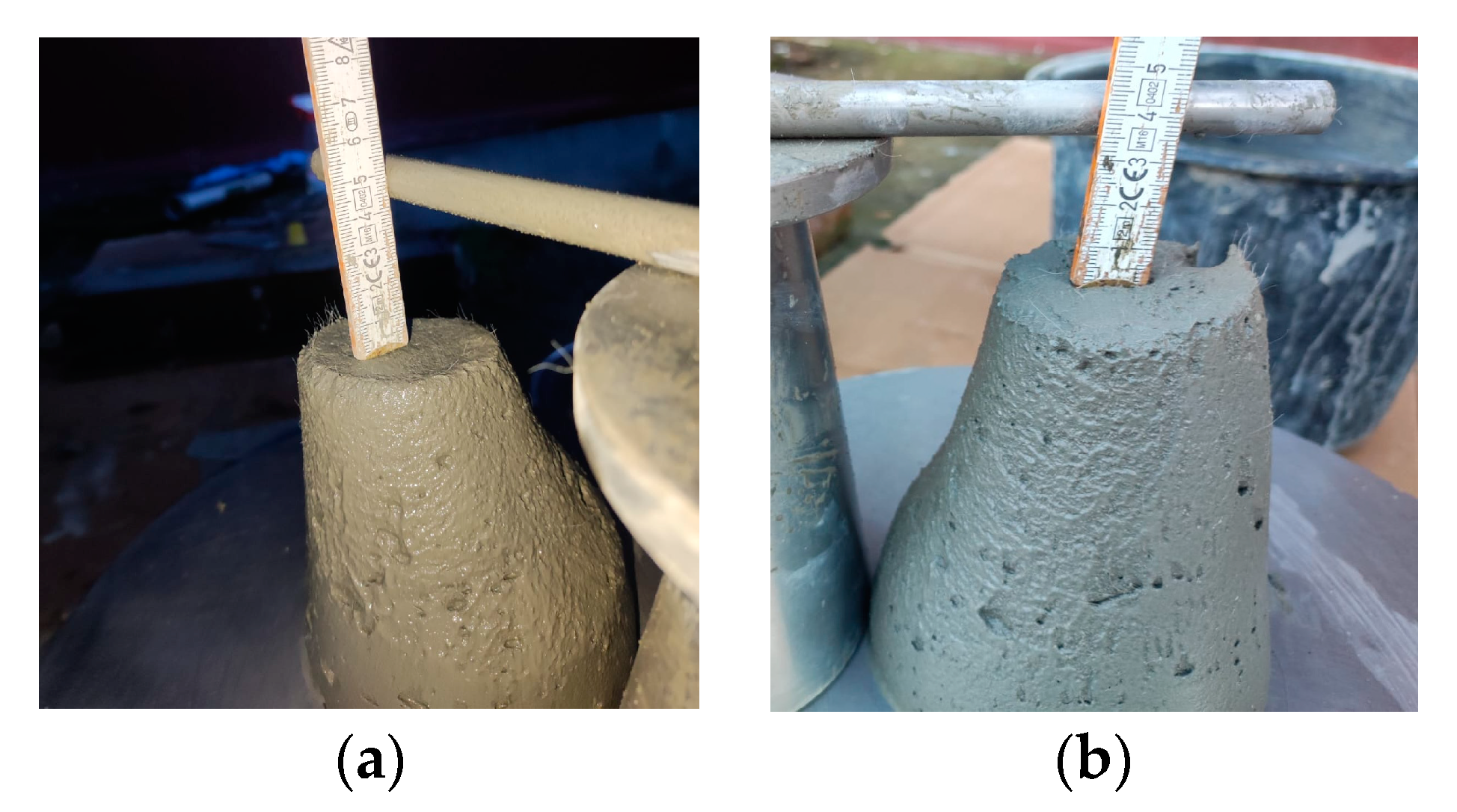
| Slum flow | 160 mm | |||||||
| Slump | 40 mm | |||||||
| Density | 2249 kg/m3 | |||||||
Disclaimer/Publisher’s Note: The statements, opinions and data contained in all publications are solely those of the individual author(s) and contributor(s) and not of MDPI and/or the editor(s). MDPI and/or the editor(s) disclaim responsibility for any injury to people or property resulting from any ideas, methods, instructions or products referred to in the content. |
© 2023 by the authors. Licensee MDPI, Basel, Switzerland. This article is an open access article distributed under the terms and conditions of the Creative Commons Attribution (CC BY) license (https://creativecommons.org/licenses/by/4.0/).
Share and Cite
Ungureanu, D.; Onuțu, C.; Isopescu, D.N.; Țăranu, N.; Zghibarcea, Ș.V.; Spiridon, I.A.; Polcovnicu, R.A. A Novel Approach for 3D Printing Fiber-Reinforced Mortars. Materials 2023, 16, 4609. https://doi.org/10.3390/ma16134609
Ungureanu D, Onuțu C, Isopescu DN, Țăranu N, Zghibarcea ȘV, Spiridon IA, Polcovnicu RA. A Novel Approach for 3D Printing Fiber-Reinforced Mortars. Materials. 2023; 16(13):4609. https://doi.org/10.3390/ma16134609
Chicago/Turabian StyleUngureanu, Dragoș, Cătălin Onuțu, Dorina Nicolina Isopescu, Nicolae Țăranu, Ștefan Vladimir Zghibarcea, Ionuț Alexandru Spiridon, and Răzvan Andrei Polcovnicu. 2023. "A Novel Approach for 3D Printing Fiber-Reinforced Mortars" Materials 16, no. 13: 4609. https://doi.org/10.3390/ma16134609