Article

In Situ Observation of the Grain Growth Behavior and Martensitic Transformation of Supercooled Austenite in NM500 Wear-Resistant Steel at Different Quenching Temperatures

1
State Key Laboratory of Refractories and Metallurgy, Key Laboratory for Ferrous Metallurgy and Resources Utilization of Ministry of Education, Wuhan University of Science and Technology, Wuhan 430081, China
2
Nanyang Hanye Special Steel Co., Ltd., Nanyang 474500, China
*
Author to whom correspondence should be addressed.
Materials 2023, 16(10), 3840; https://doi.org/10.3390/ma16103840
Submission received: 24 April 2023 / Revised: 12 May 2023 / Accepted: 17 May 2023 / Published: 19 May 2023
(This article belongs to the Topic Microstructure and Properties in Metals and Alloys)

Abstract

:
In situ observations of the austenite grain growth and martensite transformations in developed NM500 wear-resistant steel were conducted via confocal laser scanning high-temperature microscopy. The results indicated that the size of the austenite grains increased with the quenching temperature (37.41 μm at 860 °C → 119.46 μm at 1160 °C) and austenite grains coarsened at ~3 min at a higher quenching temperature of 1160 °C. Furthermore, a large amount of finely dispersed (Fe, Cr, Mn)3C particles redissolved and broke apart at 1160 °C, resulting in many large and visible carbonitrides. The transformation kinetics of martensite were accelerated at a higher quenching temperature (13 s at 860 °C → 2.25 s at 1160 °C). In addition, selective prenucleation dominated, which divided untransformed austenite into several regions and resulted in larger-sized fresh martensite. Martensite can not only nucleate at the parent austenite grain boundaries, but also nucleate in the preformed lath martensite and twins. Moreover, the martensitic laths presented as parallel laths (0~2°) based on the preformed laths or were distributed in triangles, parallelograms, or hexagons with angles of 60° or 120°.

1. Introduction

Wear, fracture and corrosion are usually the main failure modes during the service of metal materials. Wear will not directly cause the failure of metal parts, but equipment parts are difficult to repair due to wear. Besides, frequent replacement significantly reduces the working efficiency and service life of equipment, thus leading to a large amount of material and energy loss [1,2,3,4]. At present, among the metal wear-resistant materials, austenitic high manganese (Mn) steel, high chromium (Cr) cast iron and low alloy wear-resistant steel are the most widely used. Among them, austenitic high manganese steel has a surface austenitic structure, quickly producing work hardening by a phase transition under strong extrusion or impact. The core of austenitic high manganese steel still retains good toughness and plasticity because of the austenitic structure [5,6,7]. However, the wear resistance of austenitic high manganese steel is relatively low under low or medium stress conditions, which severely limits their application scope in the wear-resistant materials field [8]. High chromium cast iron, as a second-generation wear-resistant material, is currently recognized as the best wear-resistant material [9,10,11]. A lot of non-network carbide M7C3 with a hardness of 1600 HV is precipitated in high chromium cast iron and the toughness and plasticity is better than that of white cast iron [12]. Therefore, mechanical equipment made of high chromium cast iron can meet the needs of long-term wear resistance in complex environments. However, due to the large number of valuable elements such as Cr and nickel (Ni), the production of high chromium cast iron is complex, which also increases the production cost and limits its wide application in industrial production [13]. In view of the many problems regarding the service and production of the above two steels, low-alloy wear-resistant steel has gradually become the research topic of the new generation of wear-resistant metal materials [14,15,16,17,18].
Various wear-resistant steel products are made by Chinese iron and steel manufacturers, among which the production technology of the products below NM400 is relatively mature. Tempered martensite is obtained by off-line re-austenitizing after rolling to improve the strength hardness, and then the toughness is improved by subsequent tempering. Martensite has ultra-high strength and hardness among the different microstructures in steel, and it is usually selected as an important microstructure in the production of ultra-high strength steel. Therefore, among all the kinds of low-alloy wear-resistant steels, martensitic wear-resistant steel is promising. The wear resistance of martensite mainly relies on its high hardness, but the wear resistance under high impact is erratic due to its poor toughness. Therefore, many studies on martensitic wear-resistant steel have focused on improving its toughness and plasticity [19,20,21]. It has been revealed that martensitic laths and blocks are the organizational units affecting strength and hardness, while martensitic packets affect the plasticity and toughness [22,23]. In addition, Liang et al. found that crack propagation could be effectively inhibited by using smaller sizes and angles of the martensitic packet [24]. The main structure control unit affecting fracture, the size of martensitic block, was identified by Inoue et al. through a study on the cleavage fracture of tempered martensitic steel [25]. Moreover, some scholars improved the fracture toughness and elongation of martensitic steel by optimizing the composition and heat treatment process, so that about 30% residual austenite was obtained at room temperature [26].
In addition, the wear resistance of martensitic steel had been studied extensively. Liang et al. reported that low-alloy martensitic wear-resistant steel exhibited better wear resistance under moderate impact wear, and its comprehensive mechanical property was more than twice that of austenitic high manganese steel [27]. Cao et al. prepared Ti-Cr-B (boron) microalloyed high-strength wear-resistant steel with tempered martensite, in which a high dislocation density and tempered carbide precipitation hardened the matrix [28]. In the work of Ma et al., they found that the solid solution carbon content in the martensitic structure was a direct factor affecting the wear resistance and subsurface hardness [29].
Research on high-grade low-alloy wear-resistant steel is insufficient. A high-grade NM500 wear-resistant steel is presented in the present study. Martensite transformation greatly influenced the microstructure and properties of the low-alloy wear-resistant steel, and the quenching temperature and the subsequent cooling also played a decisive role in these properties. However, few studies about NM500 wear-resistant steel have studied the relationship between grain growth and martensite transformation. Moreover, a dynamic investigation into austenite grain growth and martensite transformation in NM500 wear-resistant steel has not been conducted. Therefore, the phase transformation behavior of NM500 wear-resistant steel in a continuous cooling process was analyzed by confocal laser scanning high-temperature microscopy (CSLM). The novelty of the present work is summarized in two aspects: (1) the grain growth behavior of high grade NM500 wear-resistant steel at two quenching temperatures was first recorded and compared and (2) the martensite transformations in different austenite grains were dynamically analyzed. The results of the present study will provide a reference to understand austenite grain growth and martensite transformation at different quenching temperatures.

2. Experimental Procedures

Figure 1 shows the VL2000DX-SVF17SP confocal laser scanning high-temperature microscope and the corresponding quenching process. This CSLM equipment consists of a flow control device, a console, a display, high temperature microscope, etc., which can observe and capture all kinds of physical and metallurgical phenomena in real time. It studies the dynamic process at a high resolution in real time through high-speed laser scanning imaging. A higher automation degree was achieved through digital image information storage and processing technology. The light source of CSLM was a blue laser, whose wavelength and resolution were about 410 nm and 0.25 μm, respectively. Various phases emerged under the effect of thermal etching, rather than chemical corrosion.
The experimental steel was a developed high-grade NM500 steel with the chemical composition Fe-0.23C-0.20Si-1.49Mn-1.15Cr-0.25Ni-0.37(Nb+V+Ti+Mo)-0.022Cu-0.00174B-0.01P-0.002S (wt.%). Figure 2 illustrates the structure of the confocal laser scanning high-temperature microscope. A small cylindrical sample with dimensions of Φ 6 mm × 5 mm was finish machined, and the two faces of the sample were polished until a mirror surface was obtained. Subsequently, the sample was placed into the Al2O3 crucible for in situ observation. Before the experiment, the sample chamber was vacuumed to 6 × 10⁻³ Pa, and then argon gas was introduced to prevent sample oxidation. Microstructure evolution was recorded throughout the whole process with a recording frequency of 5 photos/s. Figure 1b demonstrates the heating process with two different quenching temperatures. Firstly, the samples were reheated to 860 °C and 1160 °C, respectively, at a rate of 5 °C/s and then held for 1 h. Subsequently, the maximum cooling rate was applied to cool the specimens to room temperature after thermal holding to simulate the quenching process. The heating rate of 5 °C/s was determined by an empirical value considering its small size. Two different quenching temperatures of 860 °C and 1160 °C were chosen according to the minimum and maximum tempering parameters in industrial production. The holding time of 1h was utilized also based on the requirements of industrial production. It should be noted that the average cooling rate during quenching was estimated to be only 8 °C/s due to the low cooling ability at a low temperature range. However, the cooling rate before martensite transformation could reach 15 °C/s, totally ensuring the martensite transformation. In addition, to facilitate the analysis of grain size evolution, the eyepiece was manually changed during the in situ observation experiment. An appropriate magnification was selected due to the different size of parent austenite grains (PAGs) at 860 °C and 1160 °C. Meanwhile, the precipitates quenched at 1160 °C were identified by transmission electron microscopy (TEM) using a thin film specimen.

3. Results and Discussion

3.1. Austenite Nucleation

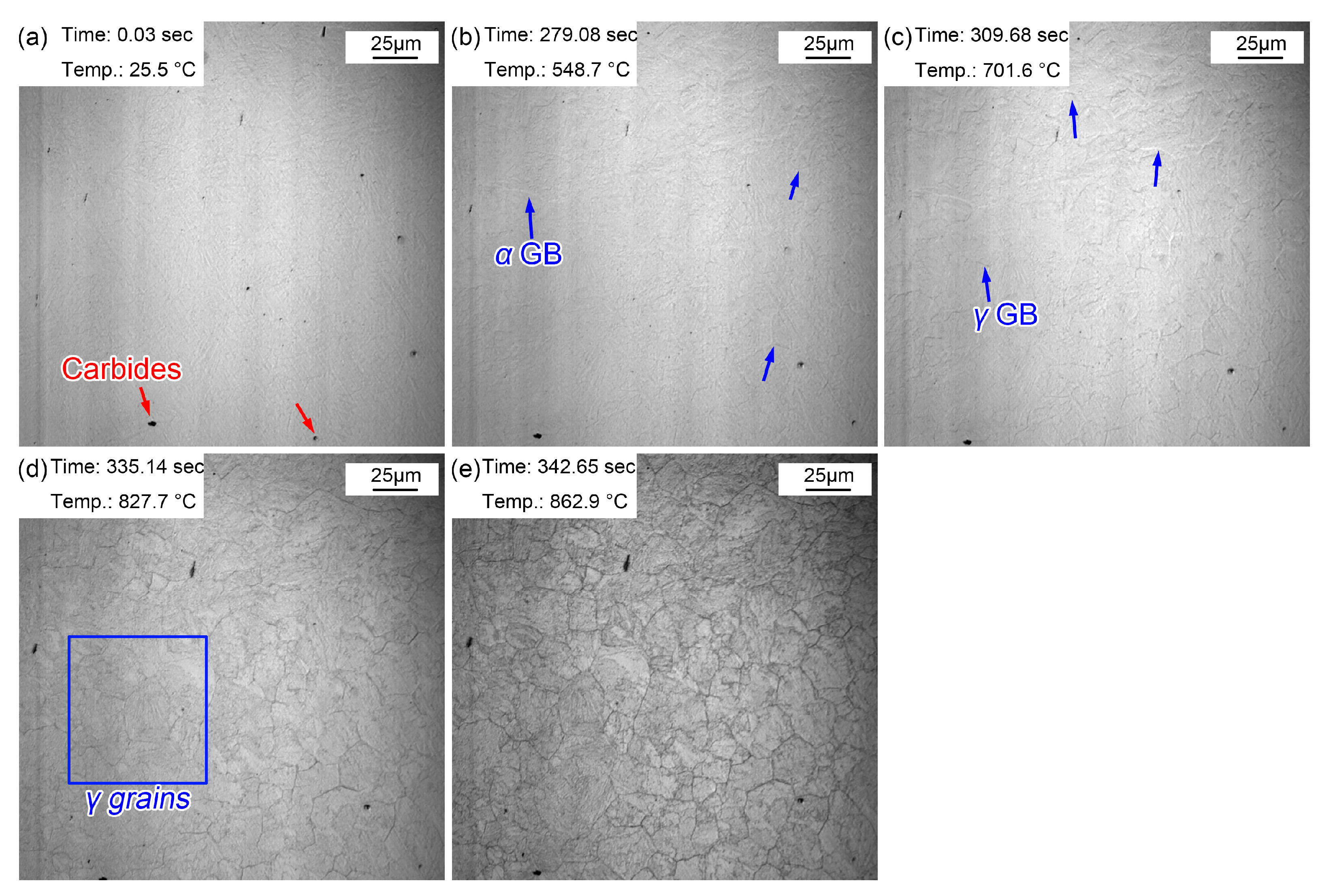
Figure 3 shows the morphologic changes from room temperature to the preset temperature of 860 °C. Some particles were present on the surface of the sample, and these dark particles were (Fe, Cr, Mn)3C precipitates (Figure 3a) determined by the following results. Due to the increased amount of Cr and Mn, (Fe, Cr, Mn)3C precipitates dominated in the as-received steel treated by hot rolling and subsequent air cooling. When the temperature was increased to 548.7 °C, some corrugated folds appeared on the sample surface. These folds correspond to the grain boundaries of the initial ferrite (pearlite), which gradually emerged under the effect of thermal etching (Figure 3b). As the temperature increased to 701.6 °C, another corrugated fold gradually covered the grain boundaries of the existing ferrite (Figure 3c). Additionally, this corrugated fold became more and more clear and gradually formed the grain boundaries of polygonal grains as the temperature rose to 827.7 °C (Figure 3d) and 862.9 °C (Figure 3e). It was inferred that the corrugated fold at 701.6 °C was an austenitic grain boundary, that is, the Ac1 temperature (the beginning temperature at which the pearlite transforms to austenite during the heating process) was about 701.6 °C when the steel was reheated at 5 °C/s. The measured Ac1 temperature of this experimental steel was about 658 °C using a thermal simulated test, a little lower than that obtained via in situ observations. The measured Ac1 temperature was obtained with a very slow heating rate (about 0.1 °C/s), and the Ac1 temperature increased with the increase in the heating rate (5 °C/s). Moreover, austenization process of the sample finished more quickly at a higher heating rate. The austenization process completed at 862.9 °C (Figure 3e), but the grain boundary morphology of the initial microstructure remained. Meanwhile, the visible (Fe, Cr, Mn)3C precipitates became clearer and their size increased.
Austenite transformation is related to the nucleation rate and the growth rate, and can be expressed as Equations (1) and (2) [30,31]:
N = f N e x p   ( Q N / K T )
G = f G e x p   ( Q G / K T )
where N is the nucleation rate, G is the growth rate, Q N and Q G are the nucleation and growth activation energies, respectively, f N and f G are the impact factors between structure and nucleation with growth, respectively, and T is the superheat. This equation reveals that the superheat increases with the increase in the heating rate, which increases the nucleation and growth rates of the austenitic transformation. Therefore, the rate of austenitic transformation increased significantly, the time required from initial austenization to complete austenization was greatly reduced, and thus the required phase transition interval was correspondingly reduced. In addition, the transformation of steel during continuous heating is equivalent to the accumulation of countless isothermal transformations. The relationship between the isothermal incubation period and the transition temperature can be established using Scheil’s superposition principle [32]:
i = 1 i = n t A i = 1
Differential Equation (4) is obtained when ∆t is small enough.
t = 0 t = t n d t A ( T ) = 1
where ∆t and dt are the transformation time at temperature T and Ai and A(T) are the corresponding incubation periods. The relationship between the incubation period and the transition temperature is shown in Equation (5):
T 1 T s d t A T = T 1 T s 1 A T · 1 d T d t · d T = T 1 T s 1 A T · 1 v · d T = 1
The relationships between the transformation rate, C, transformation beginning and ending temperatures, Ts and Tf, and the heating rate, v, are interpreted by Equations (6) and (7), where the transformation volume is f.
c = d f d t , v = d T d t
t = 0 t = t n d f d t d t = T s T f d f d t · d T v = T s T f C v · d T = 1
where T1 is the equilibrium temperature and tn is the time to the transformation ending temperatures Tf. This equation proves that with the increase in the heating rate, both the initial temperature and the end temperature of the phase transition increase. In addition, the dissolution and diffusion of carbonitrides is inevitable during the austenization process of experimental steel, and atoms migrate between phases through the diffusion mechanism. With the increase in the heating rate, the diffusion of carbon and alloying elements at the equilibrium temperature decreases, thus increasing the austenitic transition temperature. In the process of continuous heating, with the increase in temperature, the diffusion coefficient and diffusion rate of atoms increase greatly, so the driving force of the austenite phase transformation is enhanced.
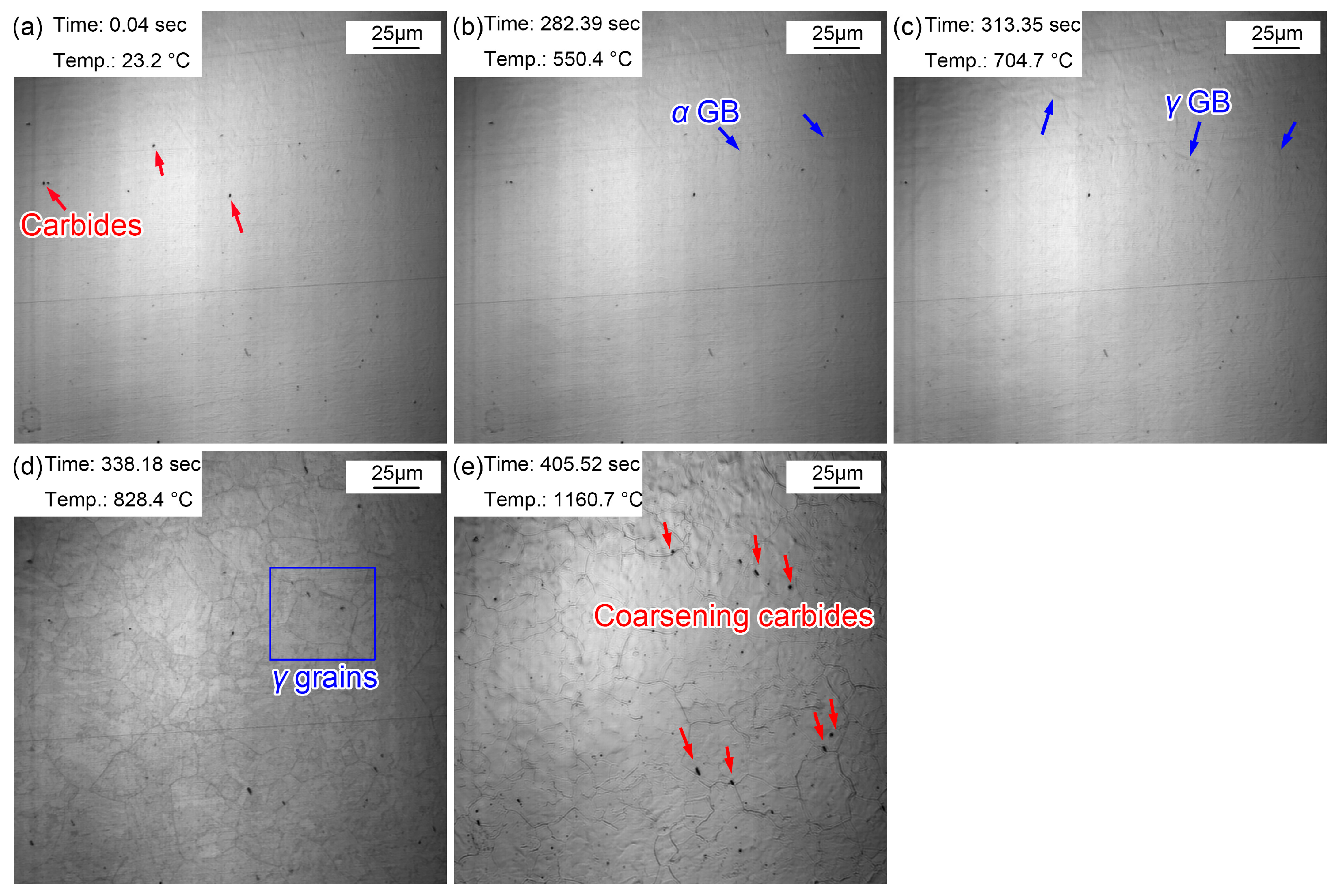
The morphological variations from room temperature to 1160 °C are displayed in Figure 4. Some (Fe, Cr, Mn)3C particles appeared on the sample surface (Figure 4a) and corrugated folds appeared at 550.4 °C (Figure 4b). Another corrugated fold gradually covered the grain boundaries of the existing ferrite structure at 704.7 °C (Figure 4c). The corrugated fold became more and more clear and gradually formed the grain boundaries of polygonal grains at 828.4 °C (Figure 4d). The Ac1 temperature was basically the same as that in specimen reheated to 860 °C. This is because the heating processes of the two samples were the same before heating to 860 °C. However, when the sample was reheated to 1160 °C (Figure 4e), more large-sized grains appeared and the grain boundaries became sharper and clearer. In addition, the number of clearly visible (Fe, Cr, Mn)3C particles increased significantly, and they gradually became more coarse. This can be explained by the gradual dissolution of some invisible finely dispersed (Fe, Cr, Mn)3C particles at 1160 °C. The austenite grain boundary mobility increased, quickly resulting in the coarsening of austenite grains. The increased amount of visible (Fe, Cr, Mn)3C particles was attributed to the ripening of more micro/nano (Fe, Cr, Mn)3C particles at high temperatures. Compared with the sample quenched at 860 °C, the austenite grains quenched at 1160 °C clearly coarsened. 
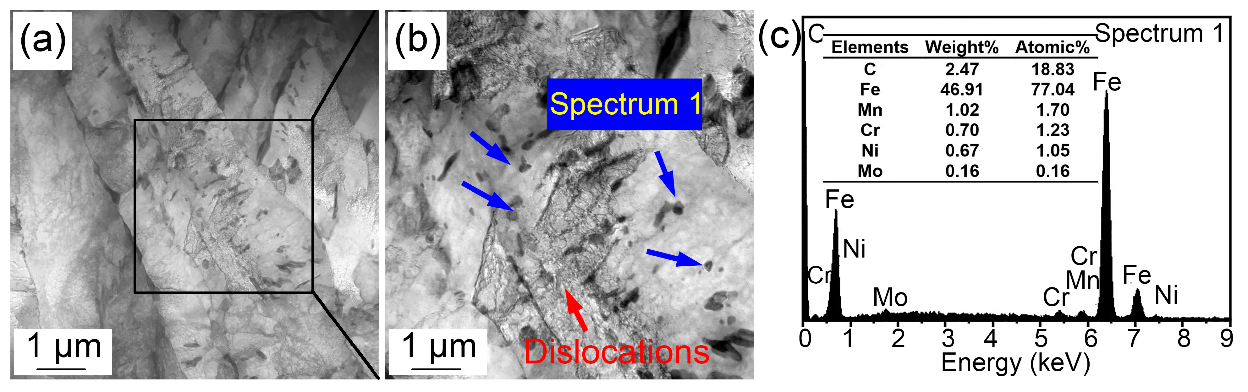
Figure 5 shows the (Fe, Cr, Mn)3C particles in the specimen quenched at 1160 °C by TEM and the related energy spectrum. (Fe, Cr, Mn)3C particles was a compound of cementite (Fe3C) with other alloy elements. A few microalloy elements such as Ti, V, and Mo were captured due to their increased solvation at higher temperatures. In addition, apparent quenching dislocations were observed in the lath martensite.

3.2. Austenite Growing

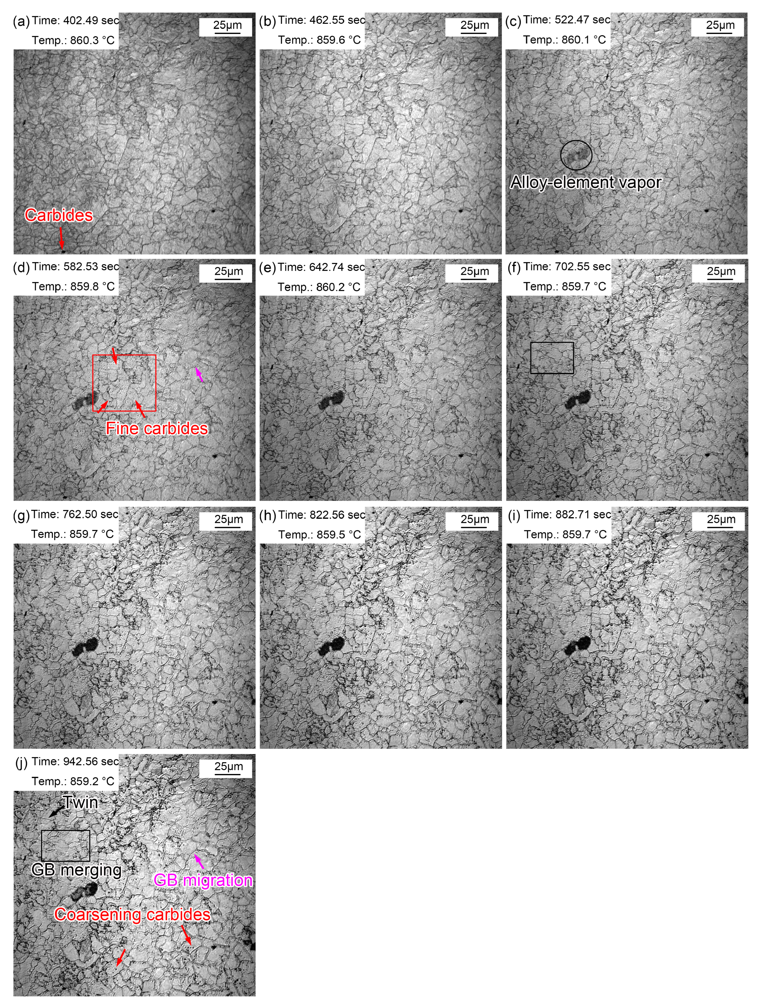
Figure 6 shows the morphologic changes from 1~10 min with a time interval of 1 min when the quenching temperature was 860 °C. Compared with the morphology after just reaching the preset temperature, the grain boundaries of austenite grains were clearer after 1 min (Figure 6a). This is because the grain boundary grooves are more easily exposed after longer thermal etching. In addition, the austenite grain boundaries were narrow and straight with a grain boundary angle of 120°. Some local small grains gradually merged into large ones, as shown in the rectangle in Figure 6f,j. In addition, the austenite grain boundaries expanded and migrated to form large grains, as shown by the pink arrows in Figure 6d,j. The gradual merging of small grains and the migration of some grain boundaries indicated a unconspicuous growth process and trend.
During the thermal holding process, a fog-like substance shown by the oval in Figure 6c appeared. The fog-like substance gradually turned black, and then subsequently disappeared. This dark mist is the vapor of alloying elements, which tends to steam outward from the steel matrix when reheated. A similar phenomenon was also reported in the research of Lan et al. [33]. Manganese (Mn) volatilization was determined by a simultaneous thermal analysis, and they clarified that Mn tended to migrate to the substrate surface and volatilize when the temperature was high enough. In addition to the clearly visible precipitates at the beginning of reheating, many fine (Fe, Cr, Mn)3C particles also appeared in the austenite grains during thermal holding, as shown in Figure 6d. These fine (Fe, Cr, Mn)3C particles gradually appeared as some of the unprecipitated (Fe, Cr, Mn)3C particles matured and emerged. The (Fe, Cr, Mn)3C particles matured during thermal holding, as shown in Figure 6j.
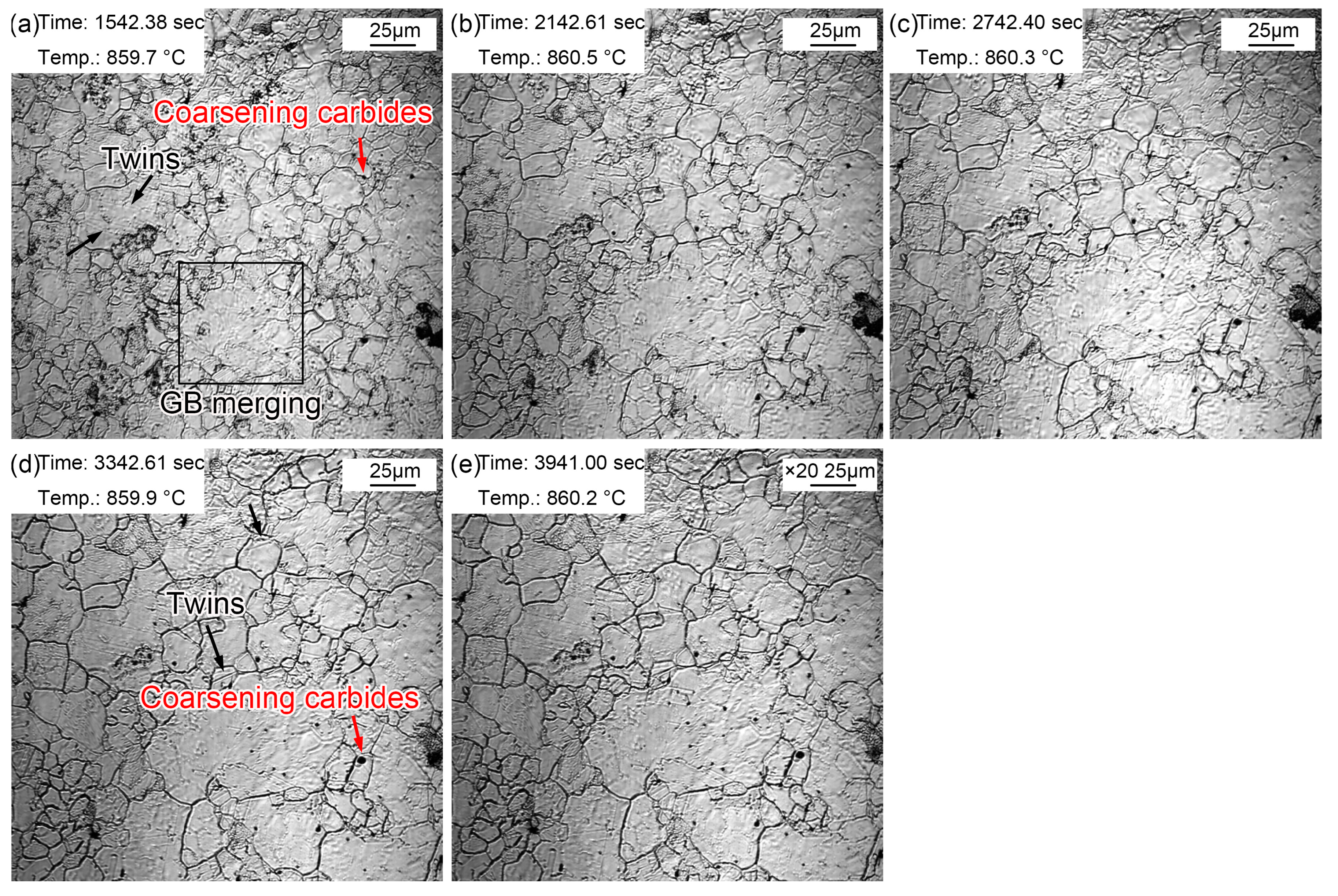
The morphologic variation in a time interval of 10 min from 20~60 min at the quenching temperature of 860 °C is exhibited in Figure 7. The coarsening of (Fe, Cr, Mn)3C particles was more obvious, and there were more areas where small grains merged into large grains. In addition, twins could be observed in austenite grains (Figure 7a). The existing fog-like steam gradually volatilized and disappeared during thermal holding, while it appeared in other areas. This may be explained by the uneven distribution of some alloying elements such as Mn. In addition, austenite grain coarsening was obvious during thermal holding, in which the proportion of small grains decreased gradually. Moreover, and the intramural twins were more clearly visible (Figure 7e). The intracrystalline twins can be considered as annealing twins [34]. There were more alloying elements in the experimental steel, which significantly reduced the stacking fault energy. Compared with ordinary carbon steel, intracrystalline twins are more likely to occur in alloyed steels. The appearance of twins segregated and refined the grains, thus increasing the resistance of dislocation movement and strengthening the steel.
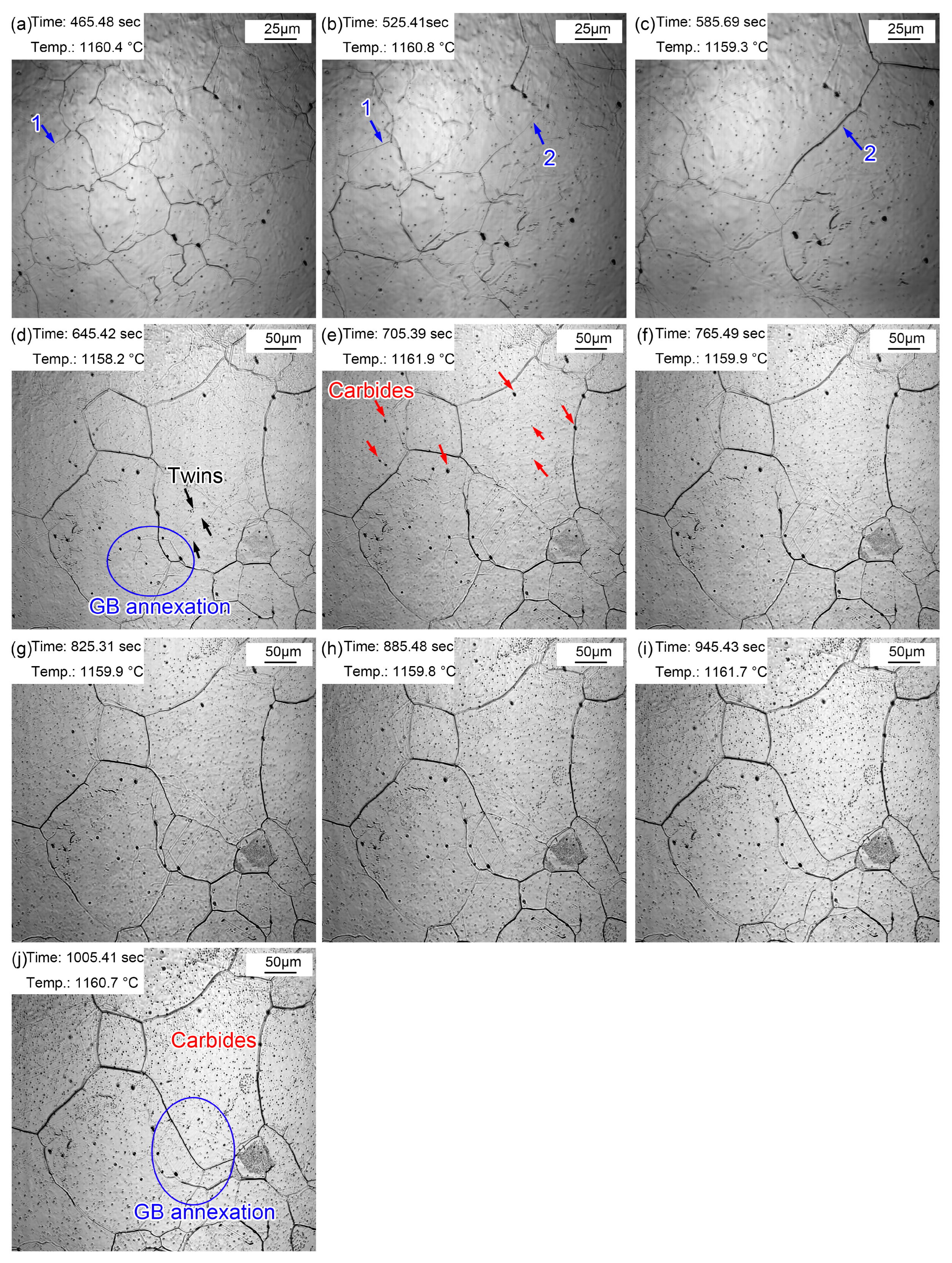
Figure 8 presents the morphologic evolution from 1~10 min at the quenching temperature of 1160 °C. The austenite grains were much clearer after holding at 1160 °C for 1 min (Figure 8a) as a result of continuous thermal etching. The migration of grain boundaries was obvious during holding, as shown in Figure 8a,b (blue arrow 1) and Figure 8b,c (blue arrow 2). Part of the original grain boundaries gradually faded away during grain boundary migration, and the old ones were gradually filled in. In addition, except for the outward expansion of grain boundaries, small grains were partitioned by surrounding large grains, as shown in the oval in Figure 8d. Alloy element steam, as shown in Figure 7c, also appeared in the specimen reheated to 1160 °C. In addition, many annealing twins traversing or occupying the whole grain were captured in the austenite grains. (Fe, Cr, Mn)3C particles ripened during the holding process, as shown in Figure 8j. The gradual appearance of fine (Fe, Cr, Mn)3C particles was attributed to (Fe, Cr, Mn)3C ripening at 1160 °C, which was captured by limited magnification. Compared with the grain morphology at 860 °C for 20~60 min, the grain size was obviously coarsened at 1160 °C, and there were many dense fine (Fe, Cr, Mn)3C particles inside the grains.
The coarsening of austenite grains at 1160 °C is related to the redissolution of (Fe, Cr, Mn)3C particles. Firstly, the atomic size of Cr/Mn/Ti is very different to Fe, which causes a certain solute atomic dragging effect. Reconcentration of a large number of solute atoms such as Cr, Mn, vanadium (V), and titanium (Ti) at the grain boundaries or subgrain boundaries could prevent the migration of grain boundaries and thus inhibit recrystallization. In addition, (Fe, Cr, Mn)3C particles were preferentially precipitated at the grain boundaries and dislocation lines, pinning the austenite grain boundaries and hindering the growth of austenite grains. Grain boundary migration caused austenite grain growth. The surface energy increased when the grain boundaries contacted the (Fe, Cr, Mn)3C particles. Only when the thermal activation energy was greater than the increased surface energy were the (Fe, Cr, Mn)3C particles cut or bypassed by the grain boundary. Therefore, the (Fe, Cr, Mn)3C particles significantly slowed down the formation of austenite and prevented the growth of grains. Similar observations were made in the work of G. Khalaj et al., where they established a model to predict the austenite grain size in Nb/Ti microalloyed steel [35]. Since the solute concentration around small particles was greater than those around large particles, the solute atoms spread from small particles to large particles, resulting in the redissolution of small particles and the growth of larger particles. Therefore, the fine precipitates gradually redissolved and continuously formed large size carbonitride particles when the holding time was long enough at 1160 °C.
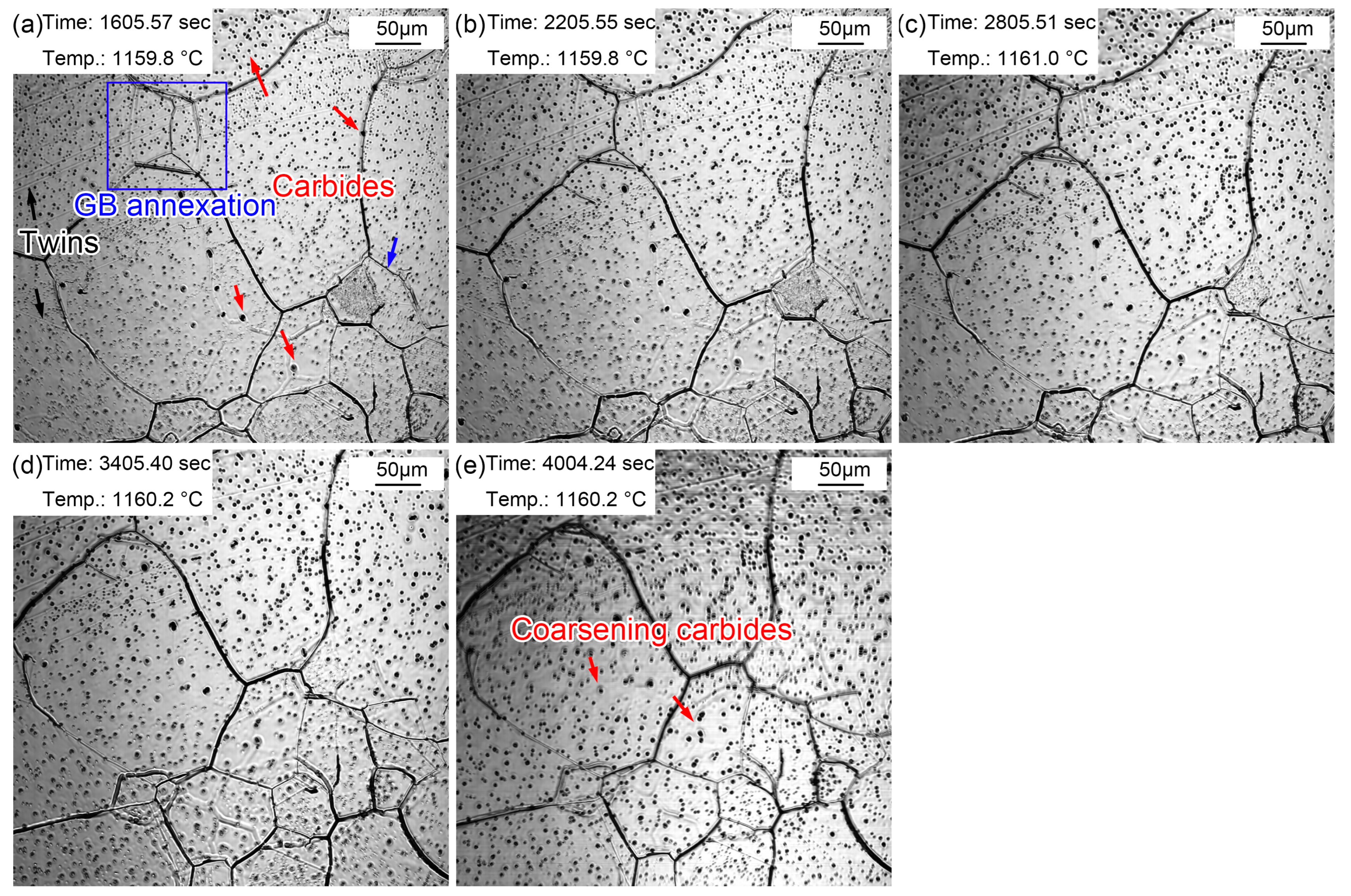
Figure 9 displays the morphologic changes with a time interval of 10 min from 20 to 60 min at 1160 °C. Dense, small (Fe, Cr, Mn)3C particles formed in the austenite grains. This signifies that the coarsening of (Fe, Cr, Mn)3C particles was more obvious compared to that during the holding time of 10 min. In addition, the grain boundaries of small-size austenite were gradually absorbed by the surrounding large-size austenite. In addition, apparent twins were observed in austenite grains (Figure 9a). Furthermore, austenite grain coarsening still occurred during holding from 20 to 60 min, in which the proportion of small grains further decreased. The intra twins were more clearly visible (Figure 9e) because of the larger austenite grains.

3.3. Grain Size

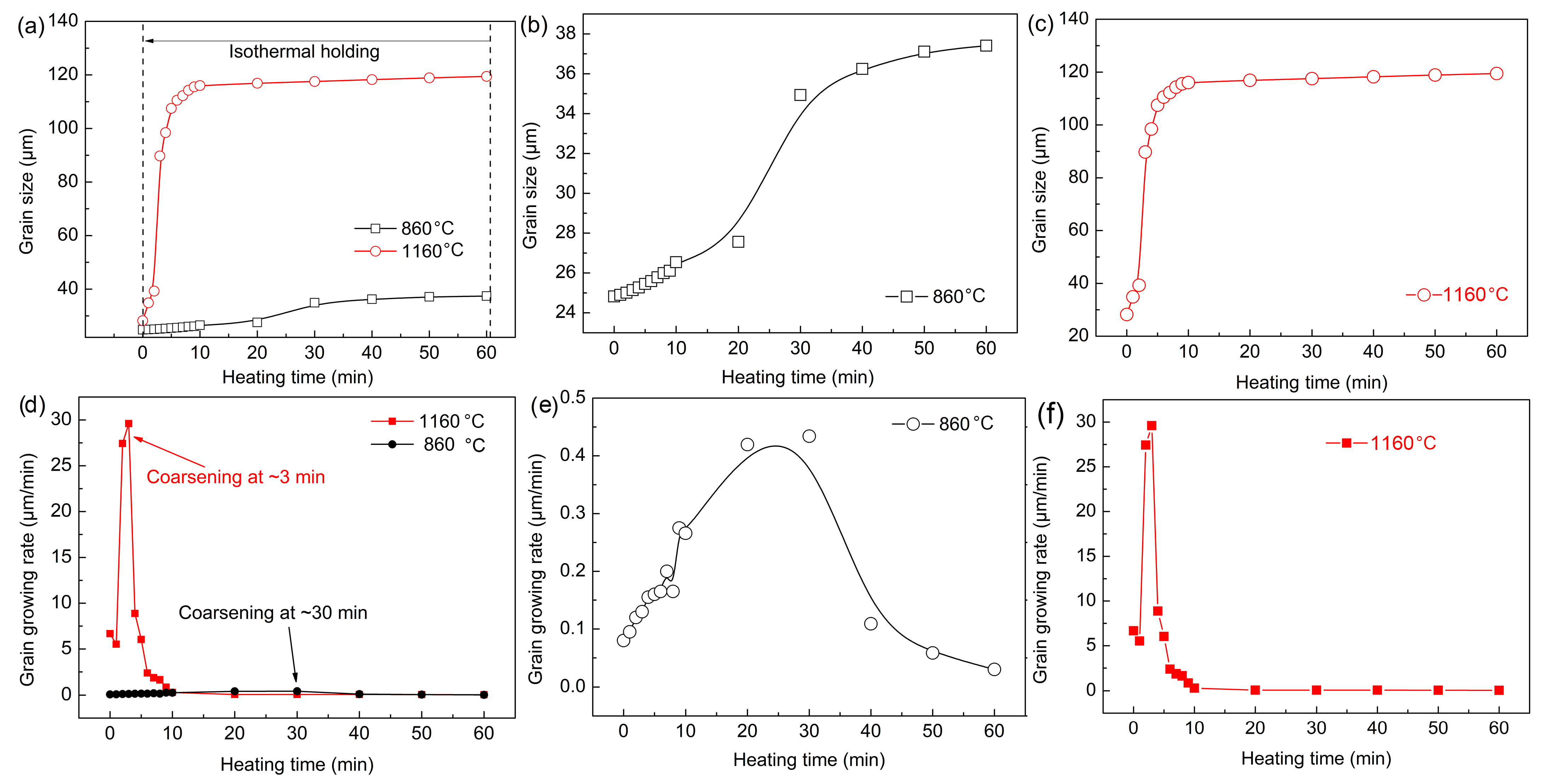
Figure 10 summarizes the grain size and growth rate of austenite at different quenching temperatures. Enough grains were present to ensure an improvement in the accuracy of the statistical process. Grains less than half the average size grain were not counted, and grains larger than half the average size grain were considered. There was little difference in the austenite grain size during the reheating stage before the preset quenching temperatures. However, the austenite grain size at 860 °C was always smaller than that at 1160 °C. Figure 10b shows the growth trend of austenite grains with time at 860 °C. The growth process was relatively slow, and the obvious coarsening of austenite grains was complete after holding for about 30 min. The growth process of austenite grains was very rapid and intense, and the coarsening of austenite grains was completed within 10 min at 1160 °C. Austenite grain growth rate curves at different quenching temperatures were obtained through the first derivative (Figure 10d–f). The austenite grain growth rate was significantly faster at 1160 °C. In addition, when the quenching temperature was 1160 °C, the maximum austenitic growth rate appeared at the holding time of ~3 min, whereas it occurred at ~30 min at 860 °C.
It can be concluded that the austenite grains coarsened in a short time and the coarsening rate was higher at 1160 °C. This is because the austenite grain boundary migration ability was increased at a higher temperature. The atomic diffusion process was more rapid, and part of the grain boundary faded and disappeared more easily. In addition, many small dispersed (Fe, Cr, Mn)3C particles redissolved and ripped, which led to a significant decrease in the migration ability of austenite grain boundaries. Furthermore, the growth rate began to decrease gradually when austenite grains coarsened extensively. This was because the energy for grain growth can no longer be provided as the heating temperature was unchanged, and the redissolution and breaking of the (Fe, Cr, Mn)3C particles was basically resolved. Consequently, the pinning effect of (Fe, Cr, Mn)3C particles on austenite grain boundaries was stabilized, so the austenite coarsening gradually weakened.

3.4. Martensite Transformation

The above-mentioned austenite grain growth rules indicated that the austenite grain size greatly varied at different quenching temperatures. It has been pointed out that the austenite grain size affected the martensitic transformation temperature and the phase transformation behavior of supercooled austenite during cooling. 
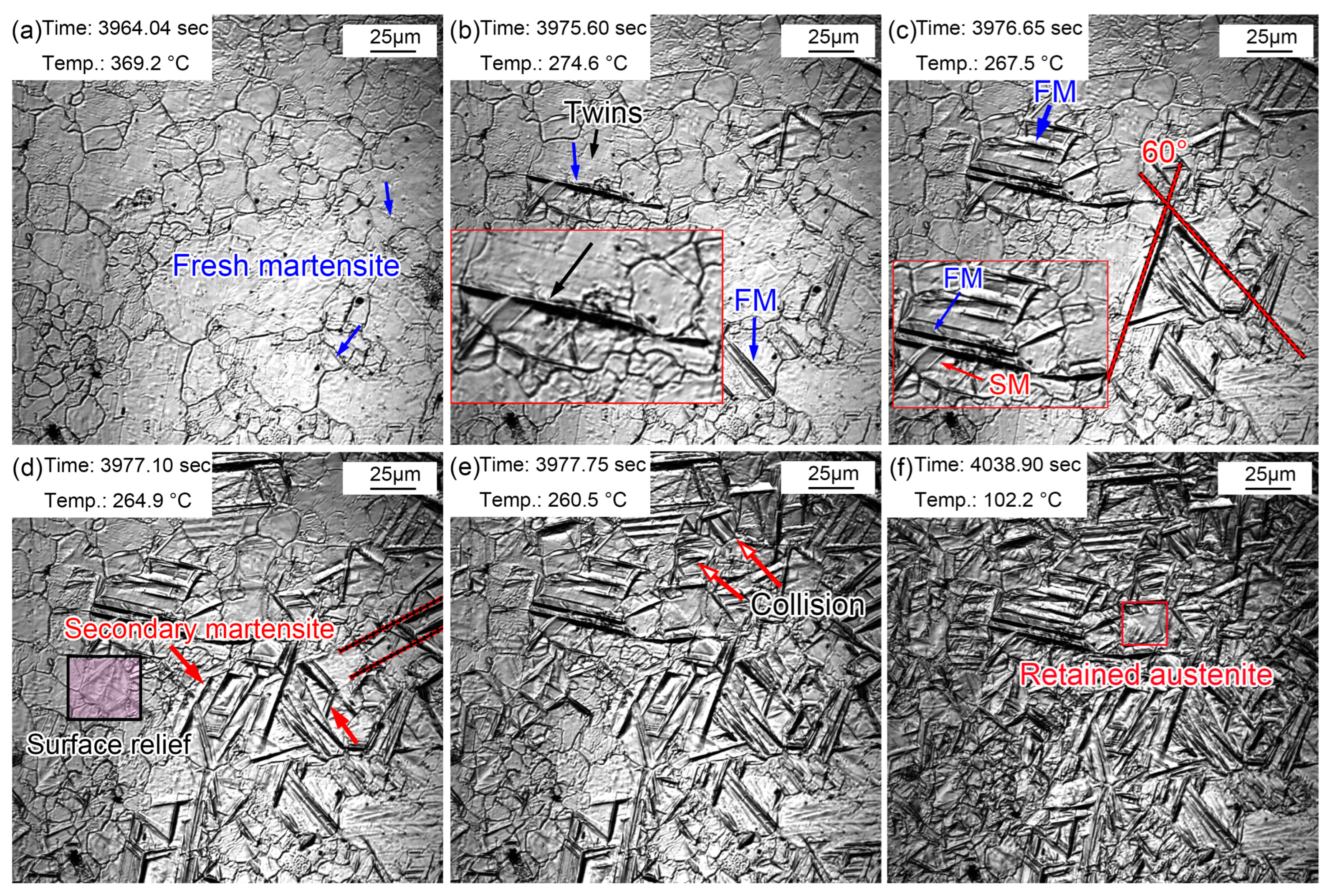
Figure 11 shows the martensitic transformation during cooling in the sample quenched at 860 °C. Lath martensite appeared, as shown by the blue arrow in Figure 11a, when the temperature decreased to 369.2 °C. This martensite was primary martensite, also called fresh martensite (FM). The martensitic phase transition point (Ms) of the sample was about 369.2 °C, while the Ms temperature of this steel was determined to be 340 °C via a thermal simulation experiment. The effective Ms was obtained via a thermal simulation experiment through the overall volume expansion effect of the martensitic transformation, while in situ observation determined the Ms just according to the temperature at which the martensite appeared in one certain grain. Generally speaking, the Ms determined by in situ observations is higher than that reflected in thermal simulation experiments. This is because the martensitic transformation does not start at the same time in all grains, although the nucleation and growth of martensite explosively proceeded following this. In addition, martensite nucleated from the grain boundary and grew in between grains until stopping at the grain boundary. More and more lath martensite explosively appeared as the temperature decreased, and most lath martensite traversed the entire grain. Furthermore, some lath martensite was found to nucleate and grow from the twins (Figure 11b). Since the formed martensite stimulated the nucleation of the surrounding untransformed austenite, the austenite nucleated and grew in parallel after this trigger. Therefore, the lath martensite grew in a parallel manner in some austenite grains. The lath martensite appeared simultaneously with an angle of 60° at 267.5 °C. In addition, some lath martensite simultaneously formed parallel to each other. More FM was observed as the temperature continued decreasing accompanied by secondary martensite (SM). SM refers to martensite with slightly thin laths formed around FM, which appeared at a certain angle with FM (Figure 11c). More and more surface reliefs due to martensitic transformations gradually appeared at the PAG boundaries (Figure 11d). Most martensite stopped growing when they encountered grain boundaries, and some martensite met each other, which also stopped the growth of lath martensite (Figure 11e). The nucleation and growth of martensite were very weak when the temperature approached room temperature. Most martensite transformations finished within 13 s, and the rate of martensitic transformations gradually slowed down. However, the distortion caused by martensitic transformations prevented martensitic transformations in the surrounding austenite. Small parts of the regions were retained as residual austenite, in which the sharing of elements such as carbon in ferrite to residual austenite was mainly completed (Figure 11f). The growth rate of lath martensite was relatively fast, but the growth rate of longitudinal lath martensite was faster than that of lateral lath martensite. Although the martensitic transformations explosively proceeded, the martensitic transformations were not simultaneous. Martensitic transformations selectively started in PAGs, but this selective process was very short. Nevertheless, the temperature of the sample may remain unchanged or even slightly increase during the cooling process since martensitic transformations release more latent heat of transformation. Therefore, isothermal martensite formation was inevitable. This latent heat caused by martensitic transformations was also one of the reasons for the selective initiation of martensitic transformations. The supercooling degree became smaller at a constant or slightly increased temperature; thus, martensitic transformations were inhibited. In addition, the selective initiation of martensitic transformations was also related to the distortion caused by martensitic transformations. Martensitic transformations in untransformed austenite were strongly inhibited by the surrounding martensitic transformations.
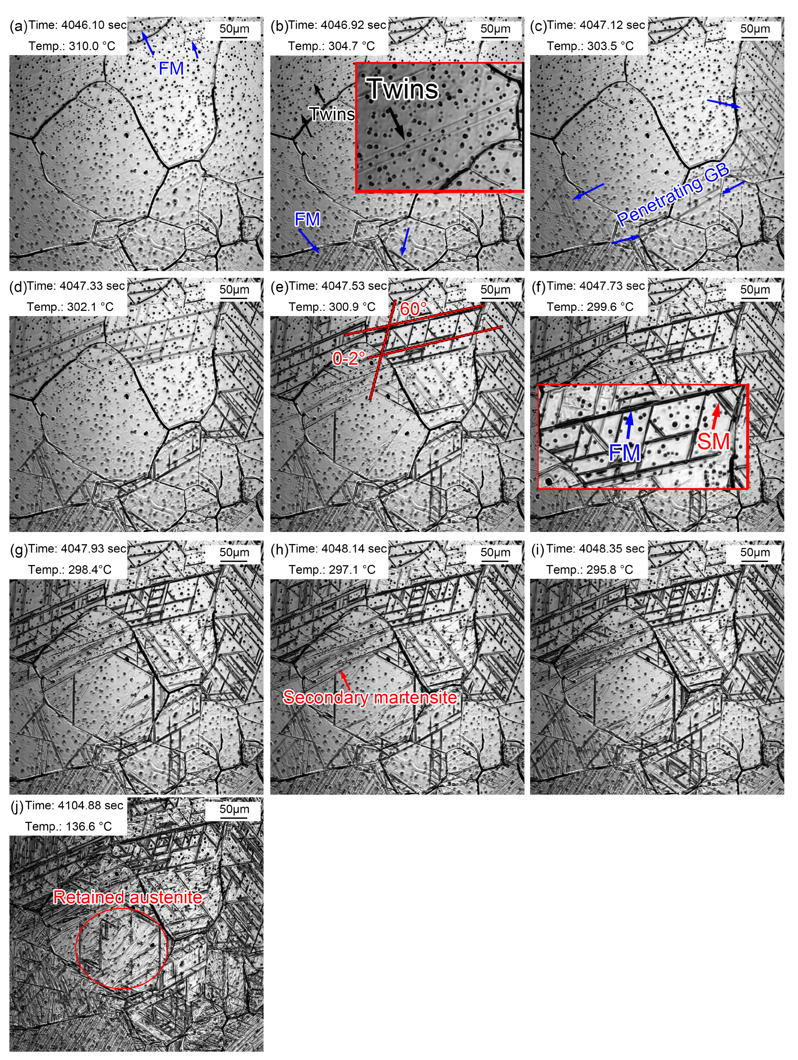
The martensitic transformation of the sample quenched at 1160 °C is displayed in Figure 12. The martensitic phase transition point, Ms, was about 310.0 °C (Figure 11a), which was lower than that in the sample quenched at 860 °C (369.2 °C). The Ms temperature should be higher in a larger austenite. However, the results of in situ observations of martensitic transformations were extraordinary. The possible reason for this is that the martensitic transformations observed by the in situ method were local to the sample surface, with a limited view field. An unobserved view field may have shown the martensitic transformations at a relatively higher temperature. In addition, it is difficult to unify the different starting temperatures of martensitic transformations due to the uneven composition caused by the evaporation of alloying elements. It was accidentally observed that lath martensite grew through grain boundaries in Figure 12c. These newly formed grain boundaries were relatively straight. In addition, some lath martensite nucleated and grew from the twins. The reason why the twins acted as martensitic nuclei was that martensitic transformations require structural and energy fluctuations. As a kind of crystal defect, twins provide a large defect energy which meets the structural and energy fluctuation requirements. Increasingly more FM and SM gradually appeared with the decrease in temperature, in which the SM appeared at a certain angle to FM. Most martensite transformations finished within 2.25 s, and the rate of martensite transformations slowed down. However, the distortion caused by martensite transformations inhibited the martensite transformations in surrounding austenite (Figure 12j). Martensite growth was a nondiffusion interfacial cooperative pushing process, and the martensite specific volume was larger than that of austenite. Therefore, elastic deformation was caused, accompanied by volume expansion, during the martensite phase transition. Additionally, then a large distortion energy formed, which hindered further martensite transformations.
Martensitic transformations in the same sample did not appear at first in large-sized grains but appeared in the PAGs in a seemingly chaotic manner. This may be explained by the differences in the size, composition, and defect density in PAGs, which led to the selectivity of martensite nuclei. In addition, the grains were coarser due to a higher quenching temperature; thus, the driving force of martensitic transformations was greater. Additionally, the migration rate of phase interfaces increased accordingly, so the martensitic transformations were faster.
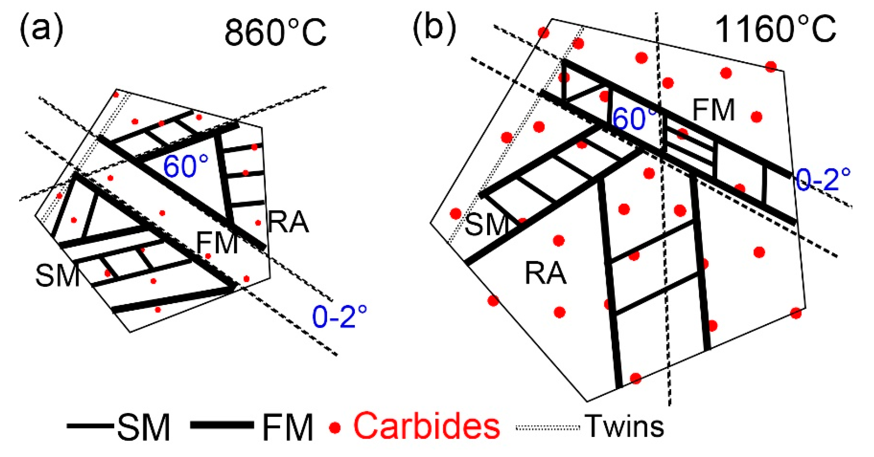
Figure 13 shows the martensitic transformation of supercooled austenite at different quenching temperatures, which is a summary based on in situ observations. Martensite nuclei did not occur simultaneously during the quenching process of supercooled austenite, but selectively proceeded and increased in batches in some areas. This nucleation pattern divided untransformed austenite into multiple regions. In different regions, the size of firstly formed martensite (fresh martensite) was large and the size of subsequent martensite (secondary martensite) was small. This is because the shape of martensite depends on the stress field between the nucleated lath martensite and other martensitic nuclei. The parent austenite presented obvious different grain sizes at different quenching temperatures. In addition, the size and volume fraction of the coarse (Fe, Cr, Mn)3C particles in the matrix increased with the quenching temperature.
Martensitic nucleation and growth in different parent austenite grains did not affect each other in the early stage of martensitic transformations, during which less martensite formed. The martensitic transformations gradually increased as the temperature decreased, and the martensitic laths restricted each other. In general, there were three types of martensitic nucleation. Firstly, martensite nucleated along the PAG boundaries and grew in between the grains until stopping when it collided with other lath martensite or grain boundaries. In addition, martensite nucleated at annealing twins, which had lattice defects and provided better structural and energy fluctuations. Moreover, martensite nucleated at the preformed lath martensite and grew in the austenitic grains at about 60° or 120° to form new lath martensite. The lath packet exhibited two types: parallel laths (0~2°) based on the preformed laths and martensitic laths at 60° or 120° in the other direction stimulated by the preformed laths, finally forming triangle, parallelogram, or hexagon morphologies. The formation of SM laths also strongly inhibited the martensitic transformations of the surrounding untransformed austenite and promoted the formation of residual austenite.

4. Conclusions

  • The austenite grains in NM500 steel at a quenching temperature of 860 °C (37.41 μm) were smaller than those at a quenching temperature of 1160 °C (119.46 μm). Austenite grains coarsened at ~3 min and ~30 min, respectively, at quenching temperatures of 1160 and 860 °C. In addition, a large amount fine dispersed (Fe, Cr, Mn)3C particles redissolved and broke apart at 1160 °C, resulting in many large, visible carbonitrides.
  • The nucleation of martensite did not proceed simultaneously during the quenching process. Selective prenucleation dominated, which divided untransformed austenite into several regions and resulted in a larger size fresh martensite compared to secondary martensite.
  • Martensite can not only nucleate at parent austenite grain boundaries, but it can also nucleate in the preformed lath martensite and twins. The larger the parent austenite grain size, the smaller the constraints of martensite growth, resulting in longer fresh martensite and secondary martensite. In addition, the martensite transformation (2.25 s) was shorter at a higher quenching temperature of 1160 °C than that (13 s) at 860 °C. In addition, martensitic lath could traverse the unstable parent austenitic grain boundaries.
  • The martensitic lath was present in parallel laths (0~2°) based on preformed laths or distributed in triangles, parallelograms, or hexagons with an angle of 60° or 120°.

Author Contributions

Methodology, Z.L., Q.Y., Y.Z. and S.L.; Formal analysis, S.X. and S.L.; Investigation, Z.L., Q.Y., Y.Z. and G.X.; Resources, S.X.; Data curation, Y.Z.; Writing—original draft, Z.L.; Writing—review & editing, Q.Y., S.X. and G.X.; Visualization, G.X.; Supervision, Z.L.; Funding acquisition, Q.Y. and S.L. All authors have read and agreed to the published version of the manuscript.

Funding

National Natural Science Foundation of China (no. 52004193), China Postdoctoral Science Foundation (no. 2022M710596), and the Joint Foundation of Nature Science Foundation of Hubei Province (2022CFD078).

Institutional Review Board Statement

Not applicable.

Informed Consent Statement

Not applicable.

Data Availability Statement

The raw/processed data required to reproduce these findings cannot be shared at this time as the data also form part of an ongoing study.

Acknowledgments

The authors gratefully acknowledge the financial support from National Natural Science Foundation of China (no. 52004193), China Postdoctoral Science Foundation (No. 2022M710596), and the Joint Foundation of Nature Science Foundation of Hubei Province (2022CFD078).

Conflicts of Interest

The authors declare no conflict of interest.

Glossary

Words/EquationsAbbreviation/Parameter Meaning
Confocal laser scanning high-temperature microscopeCSLM
Parent austenite grainsPAGs
Fresh martensiteFM
Secondary martensiteSM
N = f N e x p   ( Q N / K T ) & G = f G e x p   ( Q G / K T ) N: the nucleation rate;
G: the growth rate;
Q N   and   Q G : the nucleation and growth activation energies;
f N   and   f G : the impact factors between structure and nucleation with growth;
T : superheat.
i = 1 i = n t A i = 1  &  t = 0 t = t n d t A ( T ) = 1 t and dt: the transformation time at temperature T;
Ai and A(T): the corresponding incubation periods.
T 1 T s d t A T = T 1 T s 1 A T · 1 d T d t · d T = T 1 T s 1 A T · 1 v · d T = 1 & c = d f d t , v = d T d t &
t = 0 t = t n d f d t d t = T s T f d f d t · d T v = T s T f C v · d T = 1
C: transformation rate;
Ts and Tf: the temperatures at the beginning and ending of the transformation;
v: heating rate;
T1: equilibrium temperature;
tn: the time to the transformation ending temperature Tf.

References

  1. Bourithis, L.; Papadimitriou, G.D. The effect of microstructure and wear conditions on the wear resistance of steel metal matrix composites fabricated with PTA alloying technique. Wear 2009, 266, 1155–1164. [Google Scholar] [CrossRef]
  2. Lee, K.; Nam, D.H.; Lee, S.; Kim, C.P. Hardness and wear resistance of steel-based surface composites fabricated with Fe-based metamorphic alloy powders by high-energy electron beam irradiation. Mater. Sci. Eng. A 2006, 428, 124–134. [Google Scholar] [CrossRef]
  3. Wei, M.X.; Wang, S.Q.; Lan, W.A.; Chen, K.M. Effect of microstructures on elevated temperature wear resistance of a hot working die steel. J. Iron Steel Res. Int. 2011, 18, 47–53. [Google Scholar] [CrossRef]
  4. Wang, W.; Song, R.; Peng, S.; Pei, Z. Multiphase steel with improved impact abrasive wear resistance in comparison with conventional Hadfield steel. Mater. Des. 2016, 105, 96–105. [Google Scholar] [CrossRef]
  5. Du, X.; Ding, H.; Wang, K.; Wu, K. Influence of impact energy on impact corrosion abrasion of high manganese steel. J. Wuhan Univ. Technol. Mater. Sci. 2007, 22, 412–416. [Google Scholar] [CrossRef]
  6. Chen, J.; Wang, J.J.; Zhang, H.; Zhang, W.G.; Liu, C.M. Evolution of deformation twins with strain rate in a medium-manganese wear-resistant steel Fe–8Mn–1C–1.2Cr–0.2V. J. Iron Steel Res. Int. 2019, 26, 983–990. [Google Scholar] [CrossRef]
  7. Si, H.; Xiong, R.; Song, F.; Wen, Y.; Peng, H. Wear resistance of austenitic steel Fe-17Mn-6Si-0.3C with high Silicon and high Manganese. Acta Metall. Sin. (Engl. Lett.) 2014, 27, 352–358. [Google Scholar] [CrossRef]
  8. Liu, Y.; Tang, Y.; Huang, G. Improvement of mechanical properties of low alloy steel with high strength and wear resistance. J. Iron Steel Res. 1999, 3, 79–81. (In Chinese) [Google Scholar]
  9. Zumelzu, E.; Goyos, I.; Cabezas, C.; Opitz, O.; Parada, A. Wear and corrosion behaviour of high Cr cast iron alloys. J. Mater. Process. Technol. 2002, 128, 250–255. [Google Scholar] [CrossRef]
  10. Zhang, A.F.; Xing, J.D.; Fang, L.; Su, J.Y. Inter-phase corrosion of chromium white cast irons in dynamic state. Wear 2004, 257, 198–204. [Google Scholar] [CrossRef]
  11. Tian, H.H.; Addie, G.R.; Visintainer, R.J. Erosion–corrosion performance of high-Cr cast iron alloys in flowing liquid–solid slurries. Wear 2009, 267, 2039–2047. [Google Scholar] [CrossRef]
  12. Chen, H.; Hu, J. Study on Carbides of High Chromium Cast Iron. J. Shanghai Inst. Technol. Nat. Sci. Ed. 2003, 3, 57–62. (In Chinese) [Google Scholar]
  13. Cui, X.; Wang, N.; Gong, P.; Yang, H.; Bai, P. Effect of C, Cr contents and heat treatment on the microstructure and mechanical properties of high chromium cast iron. J. Inn. Mong. Univ. Technol. 2016, 4, 277–282. (In Chinese) [Google Scholar]
  14. Tkowska, B.; Dziurka, R.; Baa, P. Analysis of phase transformations of supercooled austenite in low-alloy steel with boron additives. Met. Sci. Heat Treat. 2016, 57, 525–530. [Google Scholar] [CrossRef]
  15. Liu, Q.; Wen, H.; Zhang, H.; Gu, J.; Li, C.; Lavernia, E.J. Effect of multistage heat treatment on microstructure and mechanical properties of high-strength low-alloy steel. Metall. Mater. Trans. A 2016, 47, 1960–1974. [Google Scholar] [CrossRef]
  16. Xu, X.; Ederveen, F.H.; van der Zwaag, S.; Xu, W. Correlating the abrasion resistance of low alloy steels to the standard mechanical properties: A statistical analysis over a larger data set. Wear 2016, 368, 92–100. [Google Scholar] [CrossRef]
  17. Sundström, A.A.; José, R.; Olsson, M. Wear behaviour of some low alloyed steels under combined impact-abrasion contact conditions. Wear 2001, 250, 744–754. [Google Scholar] [CrossRef]
  18. Fu, H.; Xiao, Q.; Fu, H. Heat treatment of multi-element low alloy wear-resistant steel. Mater. Sci. Eng. A 2005, 396, 206–212. [Google Scholar] [CrossRef]
  19. Kaijalainen, A.J.; Suikkanen, P.P.; Limnell, T.J.; Karjalainen, L.P.; Kömi, J.I.; Porter, D.A. Effect of austenite grain structure on the strength and toughness of direct-quenched martensite. J. Alloys Compd. 2013, 577, 642–648. [Google Scholar] [CrossRef]
  20. Zhang, C.Y.; Wang, Q.F.; Kong, J.L.; Xie, G.Z.; Wang, M.Z.; Zhang, F.C. Effect of martensite morphology on impact toughness of ultra-high strength 25CrMo48V steel seamless tube quenched at different temperatures. J. Iron Steel Res. Int. 2013, 20, 62–67. [Google Scholar] [CrossRef]
  21. Liang, Y.; Long, S.; Xu, P.; Lu, Y.; Jiang, Y.; Liang, Y.; Yang, M. The important role of martensite laths to fracture toughness for the ductile fracture controlled by the strain in EA4T axle steel. Mater. Sci. Eng. A 2017, 695, 154–164. [Google Scholar] [CrossRef]
  22. Fazaeli, A.; Ekrami, A.; Kokabi, A.H. Microstructure and mechanical properties of dual phase steels, with different martensite morphology, produced during TLP bonding of a low C-Mn steel. Met. Mater. Int. 2016, 22, 856–862. [Google Scholar] [CrossRef]
  23. Li, S.; Zhu, G.; Kang, Y. Effect of substructure on mechanical properties and fracture behavior of lath martensite in 0.1C-1.1Si-1.7Mn steel. J. Alloys Compd. 2016, 675, 104–115. [Google Scholar] [CrossRef]
  24. Liang, Y.; Lei, M.; Zhong, S.; Jiang, S. The relationship between fracture toughness and notch toughness, tensile ductilities in lath martensite steel. Acta Metall. Sin. 1998, 9, 950–958. [Google Scholar]
  25. Inoue, T.; Matsuda, S.; Okamura, Y.; Aoki, K. The fracture of a low carbon tempered martensite. Trans. JIM 1970, 11, 36–43. [Google Scholar] [CrossRef]
  26. Xie, Z.; Shang, C.; Zhou, W.; Wu, B. Effect of retained austenite on ductility and toughness of a low alloyed multi-phase steel. Acta Metall. Sin. 2016, 2, 224–232. [Google Scholar]
  27. Liang, G.; Xu, Z.; Li, J.; Jiang, Q. The latest development of anti-wear steel. Spec. Steel 2002, 23, 1–7. [Google Scholar]
  28. Cao, Y.; Wang, Z.; Jiang, Z.; Zhang, T.; Wang, C.; Wu, D. Development and research of wear-resistant steel with high strength and toughness. Steel Roll. 2011, 28, 3–7. [Google Scholar]
  29. Li, X.L.; Wang, C.H.; Lu, L.U. Microstructure and impact wear resistance of TiN reinforced high manganese steel matrix. J. Iron Steel Res. Int. 2012, 19, 60–65. [Google Scholar]
  30. Liu, N.; Liu, Z.D.; He, X.K.; Yang, Z.Q. Austenite transformation of SA508Gr.4N steel for nuclear reactor pressure vessels during heating process. Heat Treat. Met. 2017, 42, 88–92. [Google Scholar]
  31. Yuan, Q.; Ren, J.; Mo, J.; Zhang, Z.; Tang, E.; Xu, G.; Xue, Z. Effects of rapid heating on the phase transformation and grain refinement of a low-carbon mciroalloyed steel. J. Mater. Res. Technol. 2023, 23, 3756–3771. [Google Scholar] [CrossRef]
  32. Ågren, J.; Vassilev, G.P. Computer simulations of cementite dissolution in austenite. Mater. Sci. Eng. 1984, 64, 95–103. [Google Scholar] [CrossRef]
  33. Lan, F.J.; Zhuang, C.L.; Li, C.R.; Chen, J.B.; Yang, G.K.; Yao, H.J. Study on manganese volatilization behavior of Fe–Mn–C–Al twinning-induced plasticity steel. High Temp. Mater. Process. 2021, 40, 461–470. [Google Scholar] [CrossRef]
  34. Khalaj, G.; Yoozbashizadeh, H.; Khodabandeh, A.; Tamizifar, M. Austenite grain growth modelling in weld heat affected zone of Nb/Ti microalloyed linepipe steel. Mater. Sci. Technol. 2014, 30, 424–433. [Google Scholar] [CrossRef]
  35. Rizi, M.S.; Minouei, H.; Lee, B.J.; Pouraliakbar, H.; Toroghinejad, M.R.; Hong, S.I. Hierarchically activated deformation mechanisms to form ultra-fine grain microstructure in carbon containing FeMnCoCr twinning induced plasticity high entropy alloy. Mater. Sci. Eng. A 2021, 824, 141803. [Google Scholar] [CrossRef]
Figure 1. (a) The confocal laser scanning high-temperature microscope and (b) in situ observation process.
Materials 16 03840 g001
Figure 2. The structure of a confocal laser scanning high-temperature microscope.
Materials 16 03840 g002
Figure 3. Morphology variations from room temperature to 860 °C. (a) 25.5 °C, before heating; (b) 548.7 °C, initial grain boundaries appeared; (c) 701.6 °C, austenization began; (d) 827.7 °C, obvious austenite grains; (e) 862.9 °C, the preset quenching temperature.
Materials 16 03840 g003
Figure 4. Morphology variations from room temperature to 1160 °C. (a) 23.2 °C, before heating; (b) 550.4 °C, initial grain boundaries appeared; (c) 704.7 °C, austenization began; (d) 828.4 °C, obvious austenite grains; (e) 1160.7 °C, the preset quenching temperature.
Materials 16 03840 g004
Figure 5. (a,b) TEM images and (c) energy spectrum showing (Fe, Cr, Mn)3C particles at 1160 °C.
Materials 16 03840 g005
Figure 6. Morphologies during thermal holding at 860 °C from 1~10 min. (a) 1 min; (b) 2 min; (c) 3 min; (d) 4 min; (e) 5 min; (f) 6 min; (g) 7 min; (h) 8 min; (i) 9 min; (j) 10 min.
Materials 16 03840 g006
Figure 7. Morphologies during thermal holding at 860 °C from 20~60 min. (a) 20 min; (b) 30 min; (c) 40 min; (d) 50 min; (e) 60 min.
Materials 16 03840 g007
Figure 8. Morphologies during thermal holding at 1160 °C from 1~10 min. (a) 1 min; (b) 2 min; (c) 3 min; (d) 4 min; (e) 5 min; (f) 6 min; (g) 7 min; (h) 8 min; (i) 9 min; (j) 10 min.
Materials 16 03840 g008
Figure 9. Morphologies during thermal holding at 1160 °C from 20~60 min. (a) 20 min; (b) 30 min; (c) 40 min; (d) 50 min; (e) 60 min.
Materials 16 03840 g009
Figure 10. (ac) Grain size and (df) growth rate of austenite from formation to thermal holding at different quenching temperatures.
Materials 16 03840 g010
Figure 11. Martensite transformations of supercooled austenite quenched at 860 °C. (a) 369.2 °C, martensite appeared; (b) 274.6 °C, martensite increased; (c) 267.5 °C, martensite nucleated and grew at the twins; (d) 264.9 °C, SM and surface relief; (e) 260.5 °C, martensitic lath collisions; (f) 102.2 °C, martensitic transformation stopped and residual austenite formed.
Materials 16 03840 g011
Figure 12. Martensite transformation of supercooled austenite quenched at 1160 °C. (a) 310.0 °C, martensite appeared; (b) 304.7 °C, martensite increased; (c) 303.5 °C, martensite traversed grain boundaries; (d) 302.1 °C, martensite increased and appeared at 60° angles; (e) 300.9 °C, martensitic packet; (f) 299.6 °C, SM increased; (gi) 298.4 °C, explosive martensite; (j) retained austenite.
Materials 16 03840 g012
Figure 13. Schematic diagram of martensitic transformations of supercooled austenite at (a) 860 °C and (b) 1160 °C.
Materials 16 03840 g013
Disclaimer/Publisher’s Note: The statements, opinions and data contained in all publications are solely those of the individual author(s) and contributor(s) and not of MDPI and/or the editor(s). MDPI and/or the editor(s) disclaim responsibility for any injury to people or property resulting from any ideas, methods, instructions or products referred to in the content.

