
Computer Simulations of Injection Process of Elements Used in Electromechanical Devices

 ,
,
Abstract
:1. Introduction
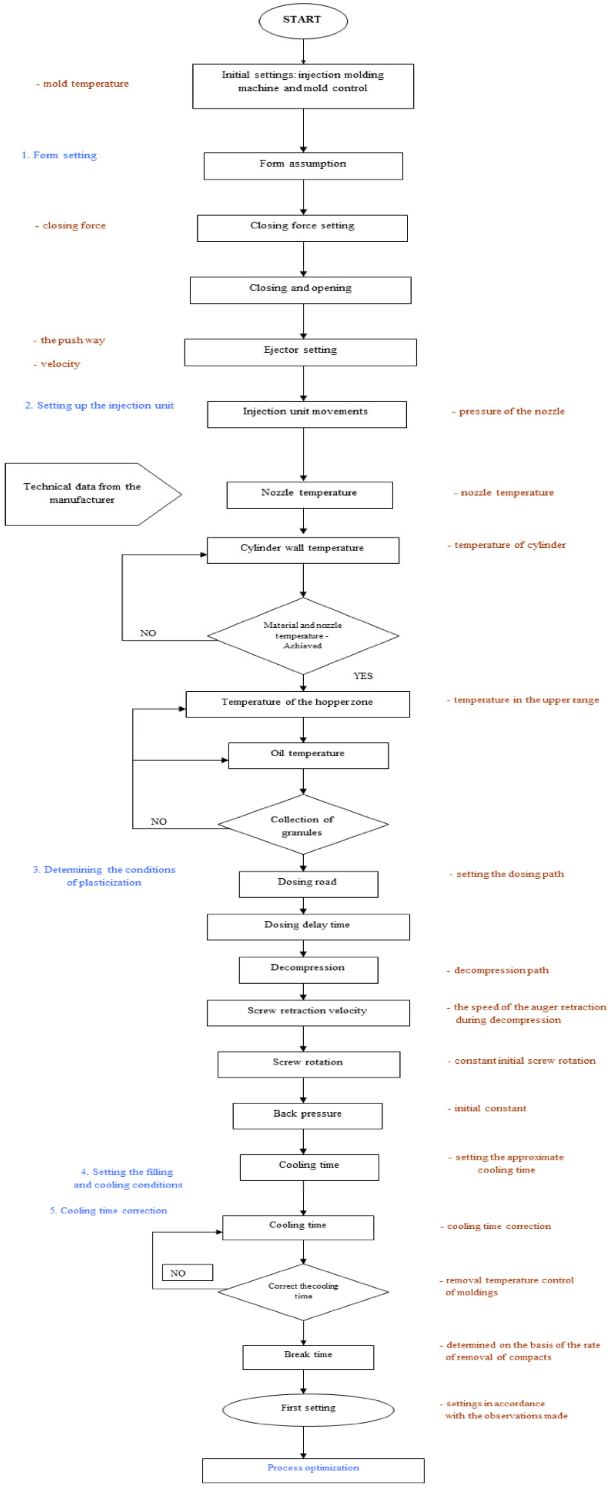
2. Organization of the Injection Process and Quality Control of Moldings
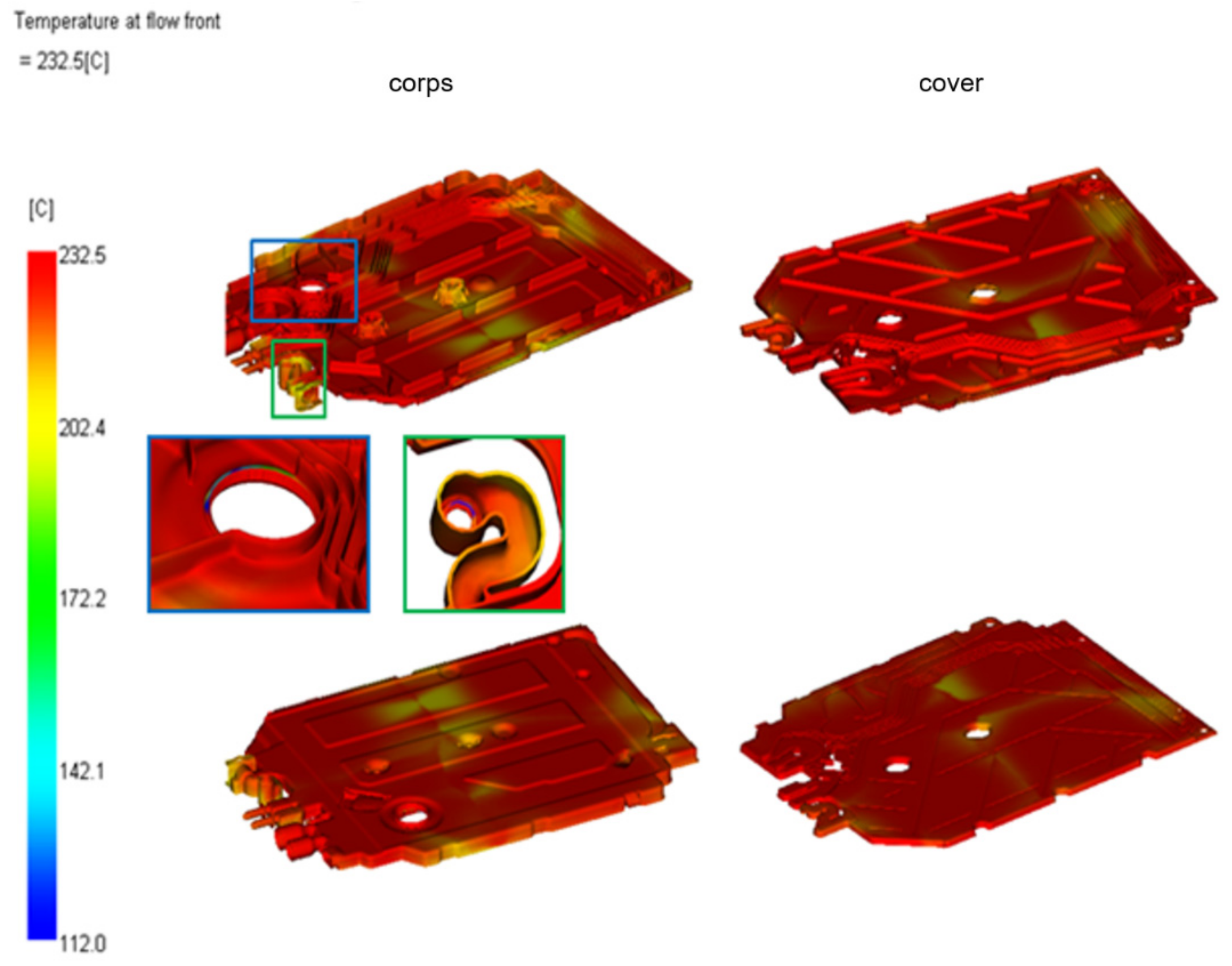
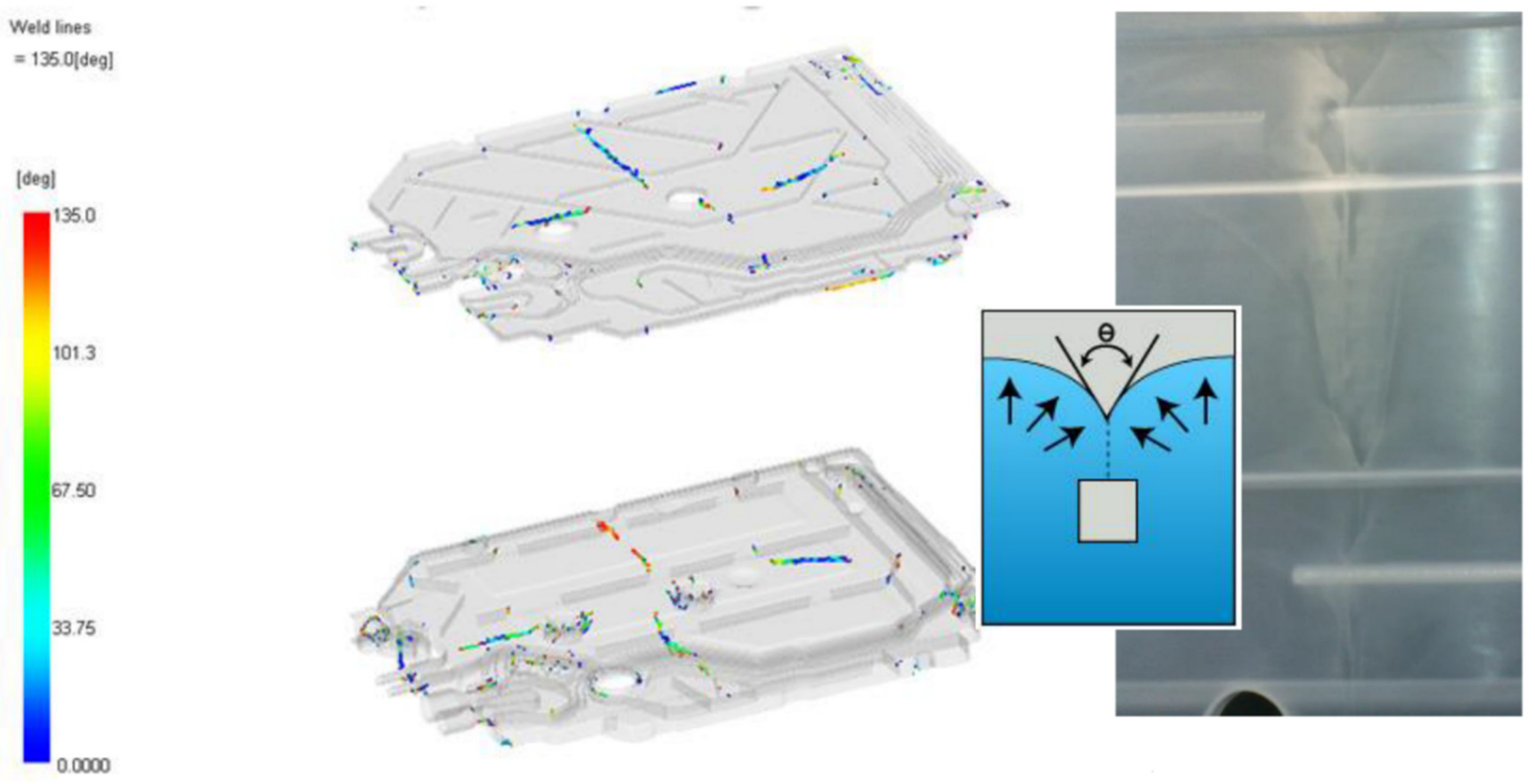
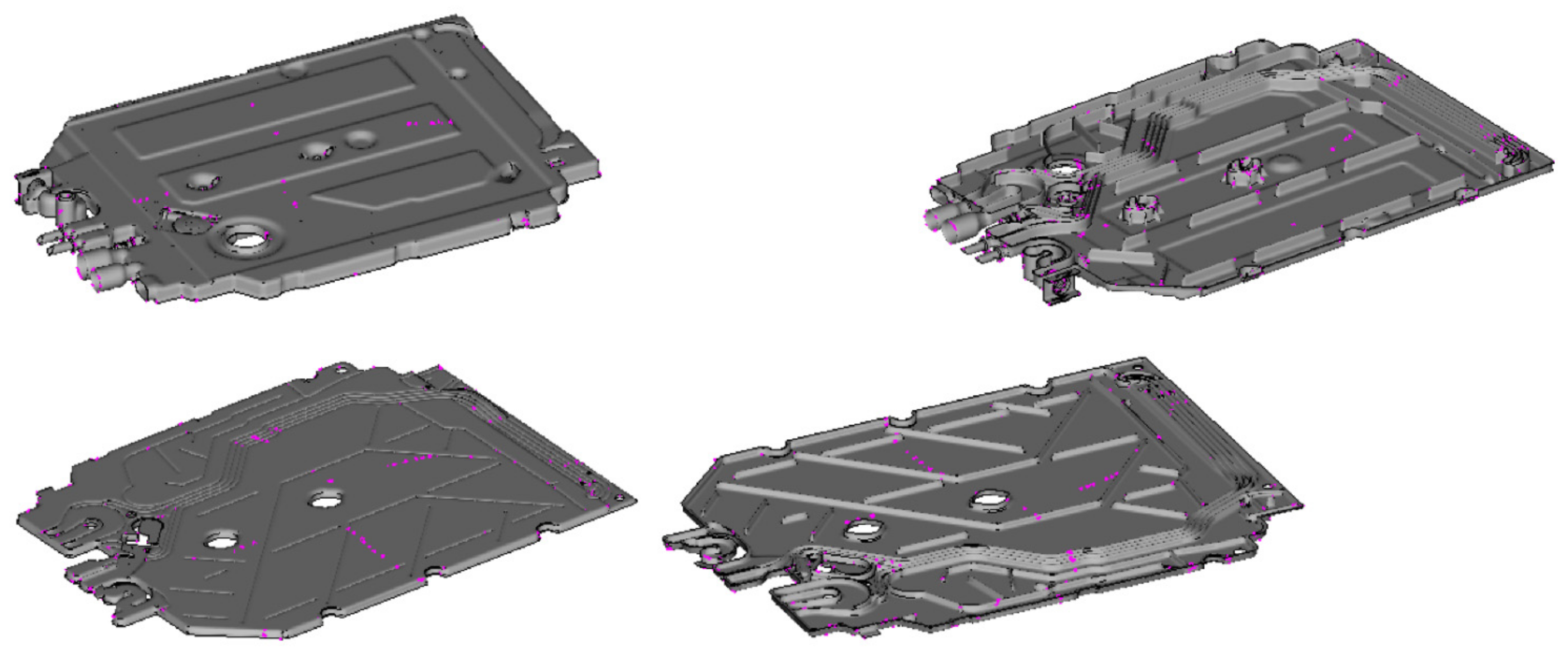
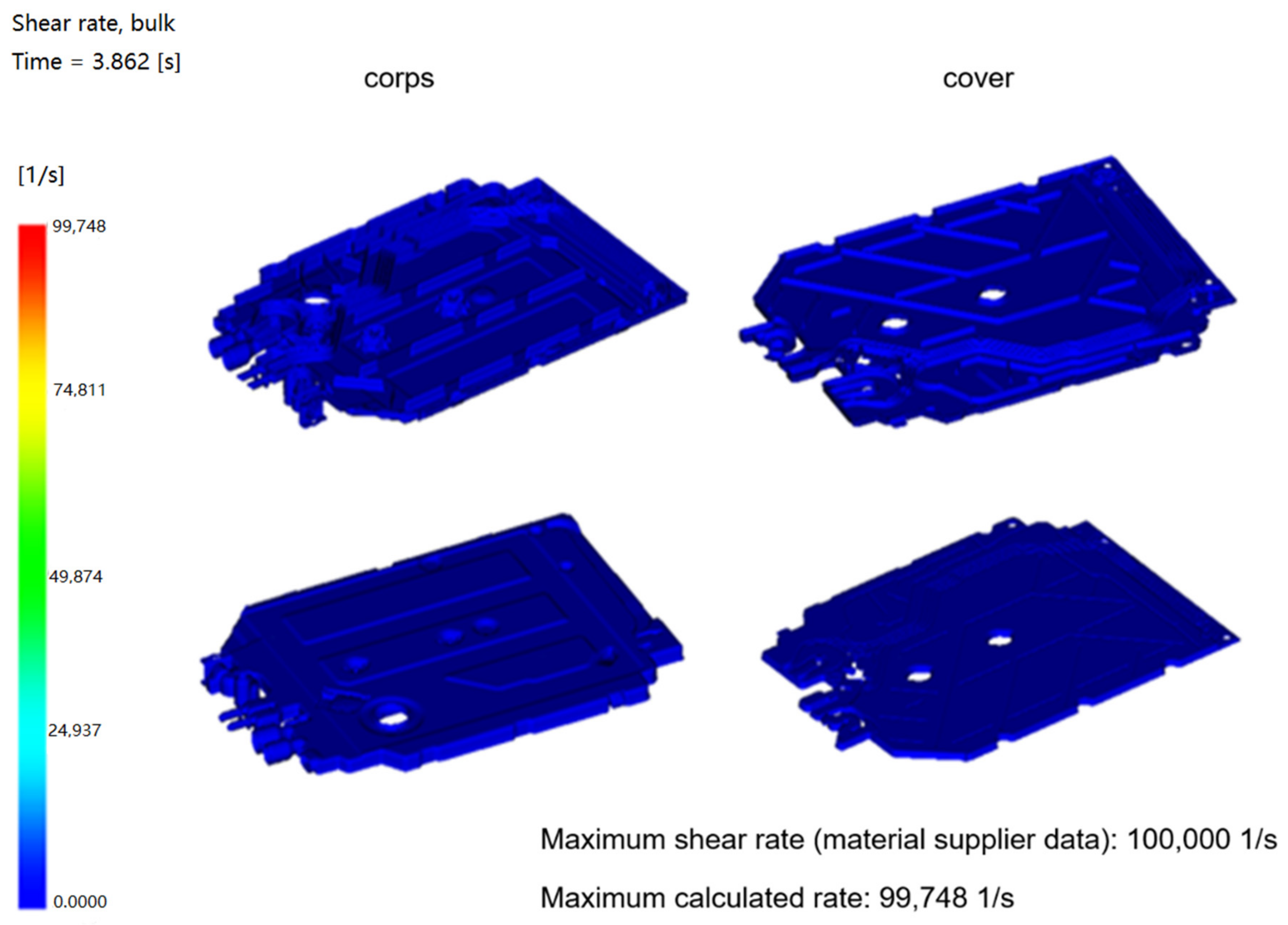
3. Analysis of the Injection Process of Detail: A Flowmeter Using the Simulation Analysis of the Injection Process in Moldflow
- determination of important areas of visual inspection (i.e., marking areas where the non-compliance has occurred or could occur in the future, e.g., the aesthetically unacceptable line connecting the streams of material, tears caused by improper setting of the process of releasing the detail from the mold cavity—traces of ejectors in difficult points, location of the area formulated by hydraulic cores, location of gas traps, etc.),
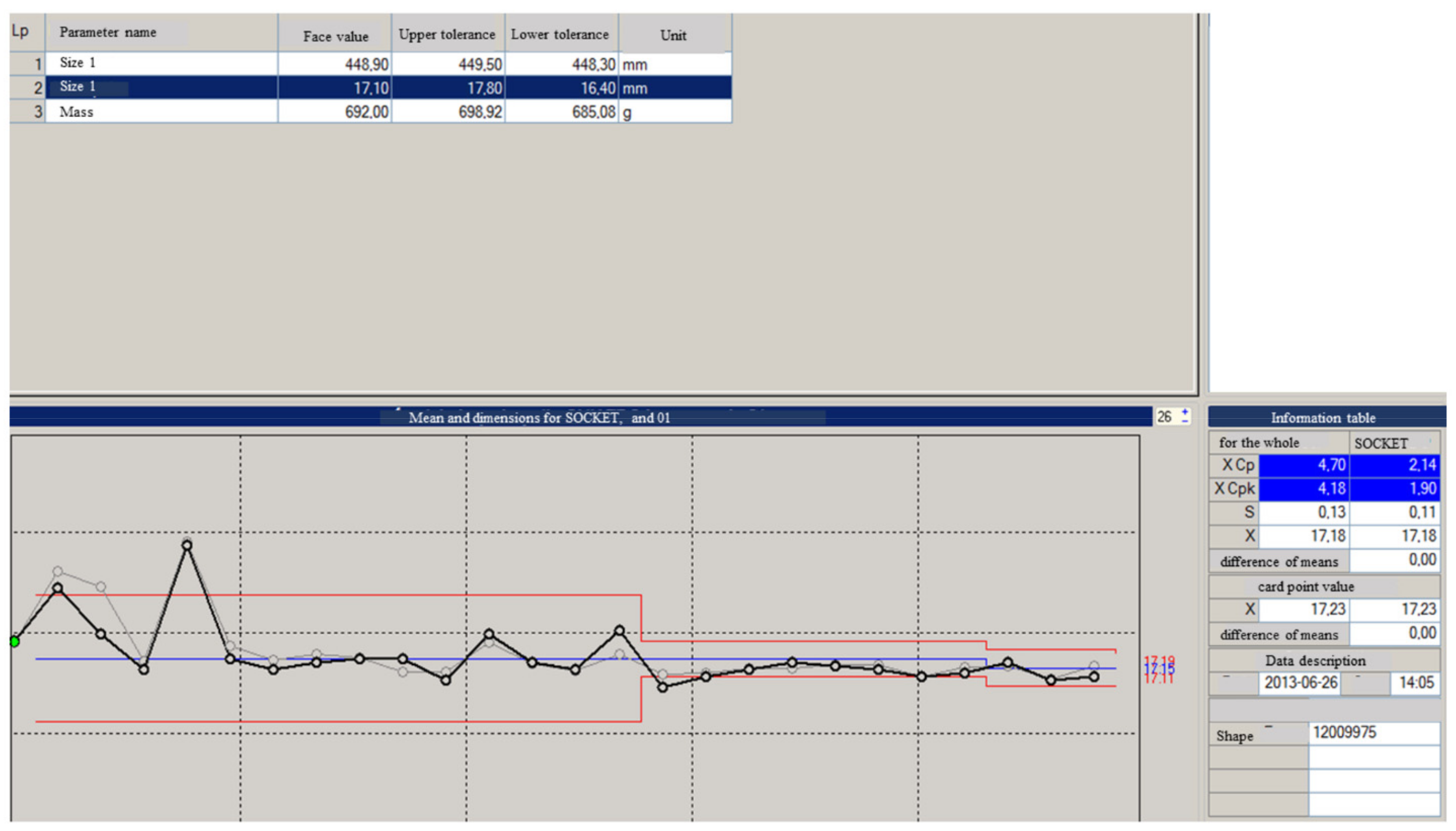
- determination of the amount of inspection frequency, which is important, for example, when injection molding parts with low grammage and usually multiple cavities, and a fairly fast cycle. Then the detail does not require 100% inspection. Of course, when inspecting a detail during the process, we analyze a set of working sockets
- determination of the method and means of control (e.g., only visual inspection or the necessity to use some kind of test).
4. Conclusions
Author Contributions
Funding
Institutional Review Board Statement
Informed Consent Statement
Data Availability Statement
Conflicts of Interest
References
- Finkeldeya, F.; Volke, J.; Zarges, J.; Heimb, H.; Wiederkehr, P. Learning quality characteristics for plastic injection molding processes using a combination of simulated and measured data. J. Manuf. Processes 2020, 60, 134–143. [Google Scholar] [CrossRef]
- Singh, G.; Verma, A. A Brief Review on injection moulding manufacturing proces. Mater. Today Proc. 2017, 4, 1423–1433. [Google Scholar] [CrossRef]
- Dang, X. General frameworks for optimization of plastic injection molding process parameters. Simul. Model. Pract. Theory 2014, 41, 15–27. [Google Scholar] [CrossRef]
- Andhalkar, V.; Dulange, S. Injection Molding Methods Design, Optimization, Simulation of Plastic Flow Reducer Part by Mold Flow Analysis. International Research. J. Eng. Technol. 2017, 4, 1742–1746. [Google Scholar]
- Miranda, D.A.; Nogueira, A.L. Simulation of an injection process using a CAE tool: Assessment of operational conditions and mold design on the process efficiency. Mater. Res. 2019, 22, e20180564. [Google Scholar] [CrossRef] [Green Version]
- Zheng, G.; Guo, W.; Wang, Q.; Guo, X. Influence of processing parameters on warpage according to the Taguchi experiment. J. Mech. Sci. Technol. 2015, 29, 4153–4158. [Google Scholar] [CrossRef]
- Chen, W.C.; Nguyen, M.H.; Chiu, W.H.; Chen, T.N.; Tai, P.H. Optimization of the plastic injection molding process using the Taguchi method, RSM, and hybrid GA-PSO. Int. J. Adv. Manuf. Technol. 2016, 83, 1873–1886. [Google Scholar] [CrossRef]
- Khosravani, M.R.; Nasiri, S. Injection molding manufacturing process: Review of case-based reasoning applications. J. Intell. Manuf. 2020, 31, 847–864. [Google Scholar] [CrossRef]
- Rosato, D.V.; Rosato, M.G. Injection Molding Handbook; Springer Science & Business Media: New York, NY, USA, 2012; pp. 1–1460. [Google Scholar]
- Ramos-De Valle, L.F. Principles of polymer processing. In Handbook of Polymer Synthesis, Characterization, and Processing; John Wiley & Sons: Hoboken, NJ, USA, 2013. [Google Scholar]
- Tadmor, Z.; Gogos, C.G. Principles of Polymer Processing; John Wiley & Sons: Hoboken, NJ, USA, 2013. [Google Scholar]
- Zhou, X.; Zhang, Y.; Mao, T.; Zhou, H. Monitoring and dynamic control of quality stability for injection molding proces. J. Mater. Processing Technol. 2017, 249, 358–366. [Google Scholar] [CrossRef]
- Kitayama, S.; Onuki, R.; Yamazaki, K. Warpage reduction with variable pressure profile in plastic injection molding via sequential approximate optimization. Int. J. Adv. Manuf. Technol. 2014, 72, 827–838. [Google Scholar] [CrossRef]
- Wang, X.; Li, H.; Gu, J.; Li, Z.; Ruan, S.; Shen, C.; Wang, M. Pressure analysis of dynamic injection molding and process parameter optimization for reducing warpage of injection molded products. Polymers 2017, 9, 85. [Google Scholar] [CrossRef] [PubMed] [Green Version]
- Huszar, M.; Belblidia, F.; Alston, S.; Wlodarski, P.; Arnold, C.; Bould, D.; Sienz, J. The influence of flow and thermal properties on injection pressure and cooling time prediction. Appl. Math. Model. 2016, 40, 7001–7011. [Google Scholar] [CrossRef] [Green Version]
- Wang, Q.; Zhen, M.; Wu, Z.; Cai, Y. Effect of Process Parameters on Cavity Pressure in Injection Molding. AIP Conf. Proc. 2017, 1820, 050005. [Google Scholar] [CrossRef]
- Azmoudeh, S.; Zamani, H.; Shelesh-Nezhad, K. Influence of Injection Molding Parameters on the Consistency of Molding Process. Appl. Mech. Mater. 2013, 446–447, 358–402. [Google Scholar] [CrossRef]
- Gnatowski, A.; Stachowiak, T. The influence of gas-assisted injection molding parameters on the structure and thermomechanical properties of hollow parts. Polym. Eng. Sci. 2013, 53, 257–262. [Google Scholar] [CrossRef]
- Hopmann, C.; Weber, M.; Reßmann, A. Effect analysis for compensating viscosity fluctuations by means of a self-optimising injection moulding proces. AIP Conf. Proc. 2015, 1664, 110004. [Google Scholar] [CrossRef] [Green Version]
- Tsai, K.; Lan, J. Correlation between runner pressure and cavity pressure within injection mold. Int. J. Adv. Manuf. Technol. 2015, 79, 273–284. [Google Scholar] [CrossRef]
- Osswald, T.; Turng, L.; Gramann, P. Injection Molding Handbook; Hanser Gardner Publications: Cincinnati, OH, USA, 2007. [Google Scholar]
- Chen, W.; Chin-Yin, H.; Ching-Ya, H. Finding an efficient frontier of process parameters for plastic injection moulding. J. Ind. Eng. Int. 2013, 9, 25. [Google Scholar] [CrossRef] [Green Version]
- Kwiatkowski, D.; Nabiałek, J.; Gnatowski, A. Numerical analysis of shrinkage and deformation of the samples senb produced with different parameters of injection molding. Composites 2010, 10, 307–311. [Google Scholar]
- Bociąga, E.; Jaruga, T.; Lubczyńska, K.; Gnatowski, A. Warpage of injection moulded parts as the result of mould temperature difference. Arch. Mater. Sci. Eng. 2010, 44, 28–34. [Google Scholar]
- Enterio, S.C. Available online: https://www.tworzywa.pl/wiedzopedia/wady-wyprasek/ (accessed on 18 December 2017).
- Plastech. Available online: https://www.plastech.pl/wiadomosci/Wady-powierzchniowe-wyprasek-smugi-2040 (accessed on 24 October 2008).
- Plastech. Available online: https://www.plastech.pl/wiadomosci/Wady-powierzchniowe-wyprasek-zapadniecia-1978 (accessed on 10 October 2008).
- Salunke, M.; Kate, R.; Lomate, V.; Sopal, G. Injection Moulding Design Methods Optimization. Int. J. Mech. Eng. Technol. 2015, 6, 33–42. [Google Scholar]
- International Organization for Standardization. ISO 9001:2015. Available online: https://www.iso.org/standards.html (accessed on 4 November 2021).
- Borealis Company. Product Data Sheet. 2021. Available online: https://www.borealisgroup.com (accessed on 31 August 2017).


| Swirls (Jetting) | ||
| drawback | cause | corrective action |
| snaky, often rough, or dull streaks appear on the surface of the molded part | this disadvantage occurs when, due to the too high injection speed, while passing through the large cross-sectional area, there is insufficient contact with the wall of the seat, which is necessary for flow laminarity. This defect may result in a deteriorated strength of the shaped body. General causes:
|
|
| Moisture streaks | ||
| drawback | cause | corrective action |
| clear, usually matte, elongated, parabolic, white or silvery, emerging on the surface moldings streaks. They are always aimed at the flowing side material |
|
|
| Burns | ||
| drawback | cause | corrective action |
| brown or silver streaks on the surface of the part from degraded plastic appear as discoloration |
|
|
| Fallsing | ||
| drawback | cause | corrective action |
| in case of uneven thickness in its place greater thickness there is a local increase effect contraction volumetric. Layer the surface is pulled inside |
|
|
| Traces of Stream Joining Lines | ||
| drawback | cause | corrective action |
| in points where when filling the nests meet two (or more) melt streams appear similar to scratches or score lines and/or differing in color be gloss areas | the possible causes incomplete fusion:
|
|
| Colored Streaks | ||
| drawback | cause | corrective action |
| they look like shadows in different colors. There are especially visible on materials from metalized or fluorescent pigments |
|
|
| An Uneven Gloss of the Part | ||
| drawback | cause | corrective action |
| the gloss on the molded part | they can be caused by:
|
|
| Not Added | ||
| drawback | cause | corrective action |
| the profile is not completely filled in some places | if unfilled part of the molded part is far from the injection point; the cause may be:
|
|
| Flowed Out | ||
| drawback | cause | corrective action |
| they appear when the material squeezes into the gaps in between in halves surface closing the mold, cores | fitting the form elements insufficient to withstand the pressure injection. Possible reasons:
|
|
| Gas or Air Bubbles | ||
| drawback | cause | corrective action |
| profile has blisters inside either on the surface |
|
|
| Black Inclusions | ||
| drawback | cause | corrective action |
| dark inclusions in the form of a point or layered |
|
|
| Lines at the Injection Point | ||
| drawback | cause | corrective action |
| the parts have fibers at the injection point |
|
|
| Concentric Tracks Near the Injection Point | ||
| drawback | cause | corrective action |
| the profile has matte concentric rings around the injection point |
|
|
| Traces of Ejectors | ||
| drawback | cause | corrective action |
| deformation from the side of pushing |
|
|
| Deformation on Removal | ||
| drawback | cause | corrective action |
| delamination on the surface of moldings resulting from insufficient adhesion of the plates of the hardened material |
|
|
| Collapses | ||
| drawback | cause | corrective action |
| the depressions are depressions on the surface of the molded part | they mainly appear in areas where more alloy is deposited, typically on the side opposite to the rib underneath. The greater the amount of alloy (thickness of the part) causes a local increase in volumetric shrinkage. This pulls the surface layer inside. If the surface layer does not flow, blisters form in place of the collapsing. Sometimes sags are formed right after the part is removed from the mold, when the hot molded core heats up the already cooled outer layers and causes them to soften |
|
| Warping | ||
| drawback | cause | corrective action |
| initially, immediately after forming, the shape of the molded part complies with that assumed in the design, and after some time, it twists and turns partially around its axis, the surface is corrugated, certain dimensions are shortened, and the angles between the walls are deformed | the reason for this is different shrinkage tendencies (so-called potential shrinkage) in different parts of the molded part. The differences in the amount of shrinkage depend on the differences in the degree of packing of the material in these parts of the compact and on the differences in the orientation of the macromolecules |
|
| Tiger Lines | ||
| drawback | cause | corrective action |
| “Tiger lines” are shadows that gradually appear on the surface of the moldings, perpendicular to the direction of flow, resembling tiger hair | they are caused by the pulsating flow of the melt, which occurs especially in the processing of multiphase thermoplastic blends (blends) |
|
| Traces of Cold Plastic | ||
| drawback | cause | corrective action |
| due to the too low temperature, portions of the polymer melt solidify in the gating system or in the injection nozzle before filling the mold cavity, and then they are injected during the next injection | this is especially true for thin-film or transparent moldings. If the polymer is not molten, it can block the cross-section available to the flowing material. In extreme cases, it may completely block the flow of plastic to the socket. As the cold material does not form a homogeneous mass with the rest of the alloy, the mechanical properties of the part are also negatively affected |
|
| Streaks (Glass Fibers) | ||
| drawback | cause | corrective action |
| the streaks of glass fibers can take the form of rough, mottled, and irregular areas on the surface of the compact, as well as certain surface irregularities which create a flow-line shape in this region of the compact | depending on the angle of incidence of the light, these streaks range in appearance from a cloudy matte to a metallic sheen. Glass fiber streaks tend to increase mainly at openings, thickness variations, curvatures, and flow lines. The formation of these defects is influenced by:
|
|
| Diesl Effect | ||
| drawback | cause | corrective action |
| the local dark discoloration appears in the areas where the streams join | the reason for this disadvantage is that it is difficult to push the air out of the mold cavity and compress it through the face of the flowing melt. If the air cannot leave the seat, it heats up so much during this compression that it “scorches” the surface of the material |
|
| Record Effect | ||
| drawback | cause | corrective action |
| the effect of the gramophone record corresponds to the traces of the melt flow lines perpendicular to the injection direction, which take the form of concentric or parallel grooves on the surface of the compact |
|
|
| Stress Corrosion | ||
| drawback | cause | corrective action |
| the external or internal scratches on the molded part are caused by stresses which are less than the destructive stresses | the level of internal stress introduced to the injection molded part is significantly influenced by the processing parameters |
|
| Scales (Dark, Silver) | ||
| drawback | cause | corrective action |
| the silver scales are visible on the surface of the molding as silvery or light to dark brown discoloration | the reason is a serious degradation of the material. The released gaseous substances form bubbles that, during the injection phase, reach the wall of the seat, where they are “smeared” on the surface. Light to dark brown discoloration often indicates severe thermal degradation due to oxidation or decomposition (often occurring after the relatively long machine stops with the heat on). Silver streaks, in turn, are usually the result of excessive friction in a limited area, i.e., in a nozzle with a too small cross-section or too thin billets |
|
| Microcracks | ||
| drawback | cause | corrective action |
| The external or internal scratches on the molded part are caused by stresses which are less than the destructive stresses. Local internal stresses between the areas with poorer packing of macromolecules are responsible for the cracking of the compacts | the formation of cracks or cracks is initiated by external stresses, often accompanied by the action of corrosive agents or fracture promoters (tensile or swelling forces increasing the notch effect). The processing parameters have a significant impact on the level of internal stresses introduced into the injection molding |
|
| Delayering | ||
| drawback | cause | corrective action |
| the delamination occurring in the moldings consists in the appearance of visible, not having good adhesion plates of the solidified alloy, or matting in the area of the surface | the reason for this insufficient adhesion between the plastic layers is excessive shear (too high shear stress) of the rather cold alloy caused by intensive cooling in the mold (mold too cold). In the case of semicrystalline materials, this may result in the formation of layers having a different crystal structure. In the case of amorphous materials, it can lead to the separation of the mixture components: polymer-sliding additives, pigments |
|
| Air Bubbles | ||
| drawback | cause | corrective action |
| if the air is trapped in the cavity and surrounded by the polymer melt, this defect can be manifested by streaks on the surface and “burns” due to the Diesel effect | then, air bubbles from below the surface of the part |
|
| Sediment on the Surface of Forming Cavity | ||
| drawback | cause | corrective action |
| the deposits (blooms) on the surface of the molding cavities are caused by the reaction of products released during polymer processing | decomposition products may include degraded polymers or their degradation products or products derived, for example, from the decomposition of flame retardants. Common causes of this defect are poor cavity venting or an excessively high processing temperature |
|
| Molding Deformation | ||
| drawback | cause | corrective action |
| the compact is deformed due to excessive stresses or their inadequate distribution during ejection | this can cause scratches, cracks, or excessive deformation of the fitting. The greatest deformations are located near the ejectors or at the undercuts that are difficult to eject |
|
| Uneven Shine | ||
| drawback | cause | corrective action |
| The gloss of the molded part depends on how well the seat surface is reproduced on it. In the case of sockets with a matt surface, its good mapping usually results in a shape with a lower gloss because the incident rays are scattered in many directions, i.e., at different angles through many rough planes. On the other hand, if the cavity surface is polished, the part usually has a higher gloss | the basic parameters influencing the removal of this defect are those responsible for the solidification of the outer or top layer and its pressure against the mold wall (mold temperature, injection temperature, injection speed and pressing time) |
|
| Insufficient Infusions | ||
| drawback | cause | corrective action |
the causes of the insufficient infusions may be:
| these resistances result from the melt viscosity, the length and cross-section of the inflow channels and the thickness of the walls of the part |
|
| Over-Infusion | ||
| drawback | cause | corrective action |
| the over-infusion may appear on the surface as protruding lamellar “projections” | they appear when the alloy is pressed between the gaps between the halves of the mold closing surfaces, the cores. This occurs, for example, when too little closing force has been applied |
|
| Part Name | Flowmeter |
|---|---|
| Part volume (total) | 1338 cm3 |
| Nominal wall thickness | 1.7 mm |
| Color change or long glass fiber | Unknown |
| Tool description | Unknown |
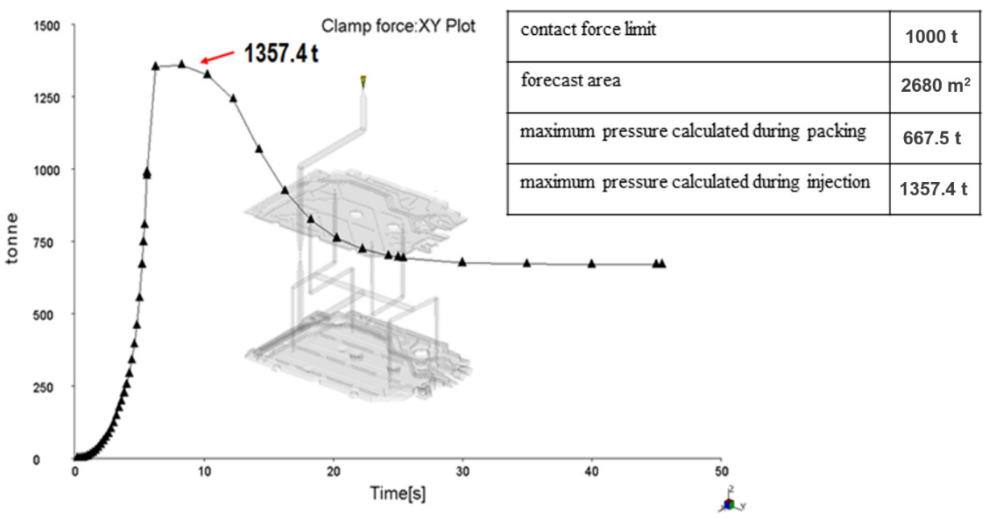
| Specified clamp tonnage limit | 1000 t |
| |
| Material | Borealis—HB 601 WG (PP) |
| Material present in Moldflow Database | Supplemental resin: Borealis—DM55 pharm (PP) |
| Melt temperature | 230 °C |
| Mold temperature | 45 °C |
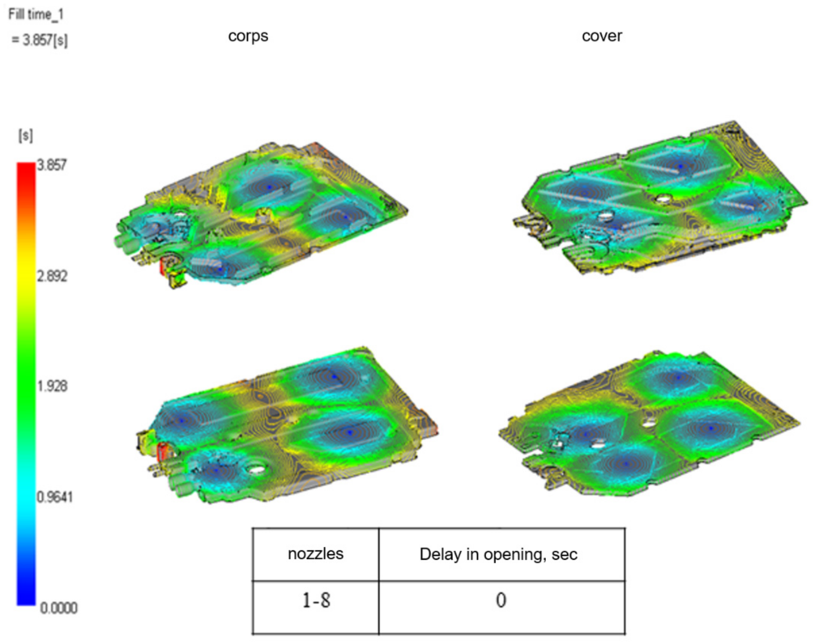
| Fill time | 2.5 s. |
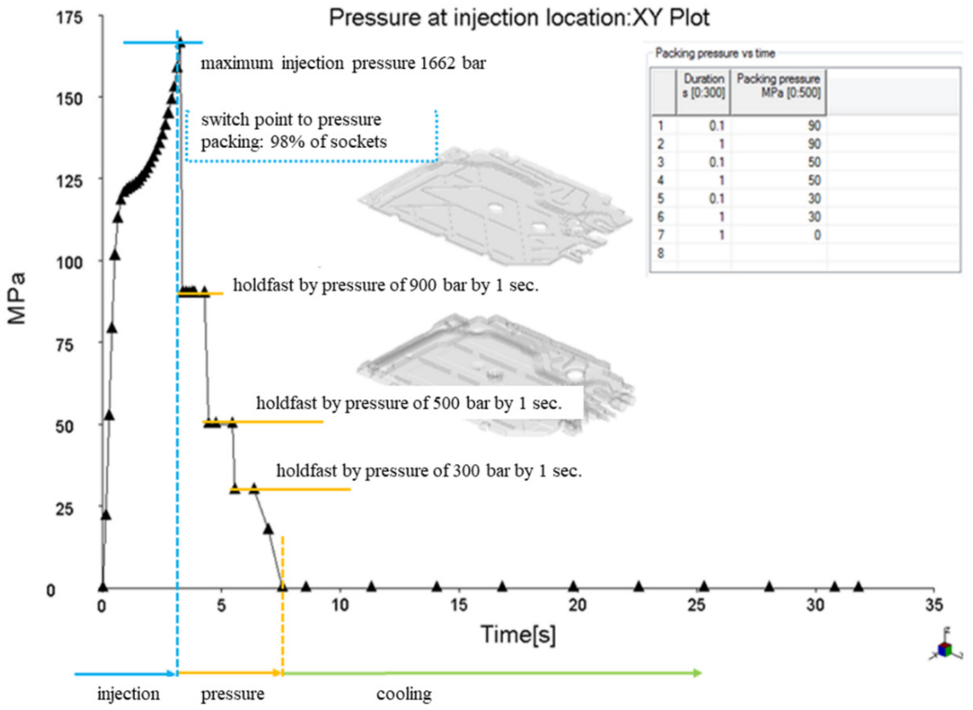
| Velocity/Pressure transfer (% volume) | 98% of volume filled |
| The result of the analysis | |
| Maximum flow rate | 334 cm3/s |
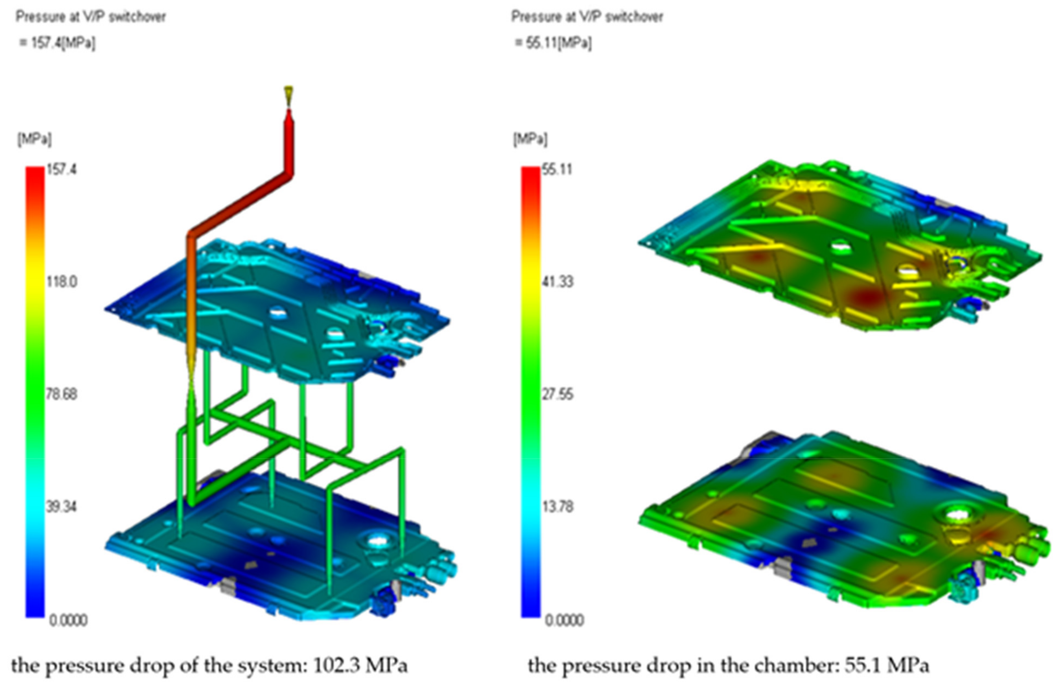
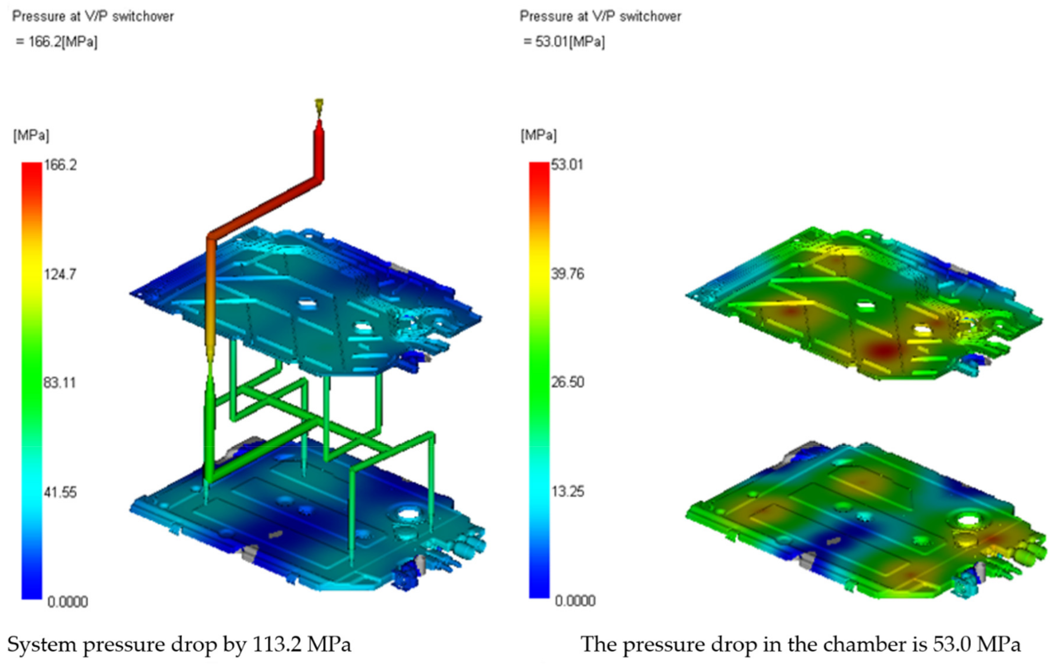
| Total system pressure | 157.4 MPa |
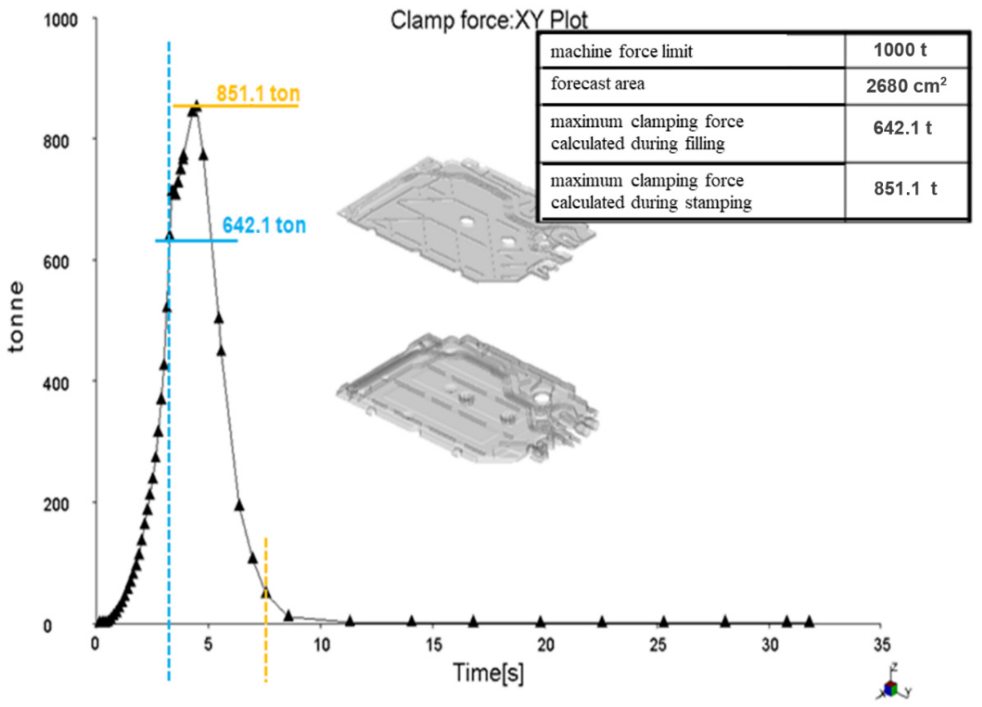
| Clamp tonnage calculation | 1357.4 t |
| Projected area | 2680 cm2 |
| Maximum melt front temperature | 230.9 °C |
| Minimum melt front temperature | 112.0 °C |
| Maximum shear rate | 65,611 1/s |
| |
| General: | Recommended processing: |
 |  |
| Process Number | Process Name | Machine, Device, Tools for Production | Characteristics | Classification | Methods | Reaction Plan | ||||||
|---|---|---|---|---|---|---|---|---|---|---|---|---|
| Product | Process | Product | Technique | Simple | Method of Control | |||||||
| No | Product | Size | Frequency | |||||||||
| Process Injection process | ||||||||||||
| — | Visual inspection | Number of form 83,002 | 1.1 | Check material correctness | — | — | System SIGIP | Visual / Operator Team leader! | Once | Each delivery from the warehouse to department | Production control sheet | Isolate materiał (PR2) |
| — | — | — | 1.2 | — | Check injection parameters | + | Card of injection parameters | Visual Operator Team leader! | Once | Start shift | Production control sheet | Isolate materiał (PR2) |
| 1.3 | — | Control of correct | + | Card of injection parameters | Process | Once | Everyday | Production control sheet | Isolate material (PR2) | |||
| — | — | — | 1.4 | Check the correctness marking part number and production data on the part | — | + | 12,009,975 Self-control instruction CO0035J2D Drawing | Visual Team leader! Operator | 1 molded piece | Start production | Production control sheet | Materiał Isolate materiał (PR2) |
| — | Packing | — | 1.9 | According to the packing card | — | — | Packaging card | Visual Team leader! Operator | 100% | Continuous | — | Isolate materiał (PR2) |
| — | Visual inspection | — | 2.1 | Control of all surfaces of the detail | — | + | 12,009,975 Self-control instruction C00035J2D Drawing | Visual quality | 1 molded piece | 3 times on shift | — | Isolate materiał (PR3) |
| — | Dimension control of part to production approval | — | 2.2 | Dimension control of part to production approval | — | SPC | C00035J2D Drawing | Bench scales Quality | 1 molded piece | 3 times on shift | Chart X-R | Isolate materiał (PR3) |
| — | Dimension control of part to production approval | — | 2.3 | Dimension control of part to production approval | — | + | 21.79 ± 0.1 mm C00035J2D Drawing | Machine 3D Metrology | 1 molded piece | Start production every quarter | Dimensional control report | Isolate materiał (PR3) |
| — | — | — | 2.4 | Dimension control of part to production approval | — | + | C00035_02D Drawing | Machine 3D Metrology | 1 molded piece | Start production every quarter | Dimensional control report | Isolate materiał (PR3) |
| — | — | — | 2.5 | Dimension control of part to production approval | — | + | 19.8 ± 0.2 mm C00035J2D Drawing | Machine 3D Metrology | 1 molded piece | Start production every quarter | Dimensional control report | Isolate materiał (PR3) |
| Product | Data | GAA | Defective | Action | Responsible | Deadline | Status | Done |
|---|---|---|---|---|---|---|---|---|
| Corps/Cover GV640 HEX | 10 | 274 | joining the material with the loss on the inner wall at the base of the detail (ribbing zone) at the weld line | Make appropriate changes to the injection process | Seters/ Technologist | 10 | Z | 10 |
| Corps/Cover GV640 HEX | 10 | 289 | Air bubbles in the front part of the detail as well as in the lower part—the anti-return valve zone | Make appropriate changes to the injection process | Technologist | 10 | 10 | |
| Corps/Cover GV640HEX | 11 | 327 | Air bubbles on the front end of the body and air bubbles at the weld line and/or the fold of the wall | Process improvement. Updating patterns with defects in the form of air bubbles marked in order to reduce the number of parts rejected by the operator during current production. Delivery of a set of OK/NOK standards also to the production line. Improvement in the field of detail quality | Technologist | 11 | 12 | |
| Corps/Cover GV640 HEX | 12 | 327 | Air bubbles occurring mainly at the weld line | Inconsistencies from the launch of production—the process is stabilizing | Technologist | 12 | 12 |
| Product | Data | GAA | Defective | Action | Responsible | Deadline | Status |
|---|---|---|---|---|---|---|---|
| Corps/Cover GV640HEX | 15 | 411 | Air bubbles on the face of the workpiece. No repeatability of non-conformities. A large number of reject parts during production. | Cleaning of mold degassing | Technologist | 16 | 0 0 |
| Corps/Cover GV640HEX | 16 | 411 | Air bubbles on the face of the workpiece. No repeatability of non-conformities. A large number of reject parts during production. | Comment: Week 20 still has air bubbles located mainly at the edge of the lid. | Technologist | 16 | |
| Corps/Cover GV640HEX | 17 | 452 | The material allowance at the injection point of the detail. | Not closing the nozzle. | Technologist | 17 | |
| Corps/Cover GV640HEX | 21 | 411 | Air bubbles on the face of the workpiece. No repeatability of non-conformities. A large number of reject parts during production. | Cleaning of mold degassing | Technologist | 23 |
Publisher’s Note: MDPI stays neutral with regard to jurisdictional claims in published maps and institutional affiliations. |
© 2022 by the authors. Licensee MDPI, Basel, Switzerland. This article is an open access article distributed under the terms and conditions of the Creative Commons Attribution (CC BY) license (https://creativecommons.org/licenses/by/4.0/).
Share and Cite
Gnatowski, A.; Kijo-Kleczkowska, A.; Krzywanski, J.; Lemanski, P.; Kopciuszewska, E. Computer Simulations of Injection Process of Elements Used in Electromechanical Devices. Materials 2022, 15, 2511. https://doi.org/10.3390/ma15072511
Gnatowski A, Kijo-Kleczkowska A, Krzywanski J, Lemanski P, Kopciuszewska E. Computer Simulations of Injection Process of Elements Used in Electromechanical Devices. Materials. 2022; 15(7):2511. https://doi.org/10.3390/ma15072511
Chicago/Turabian StyleGnatowski, Adam, Agnieszka Kijo-Kleczkowska, Jaroslaw Krzywanski, Przemyslaw Lemanski, and Elzbieta Kopciuszewska. 2022. "Computer Simulations of Injection Process of Elements Used in Electromechanical Devices" Materials 15, no. 7: 2511. https://doi.org/10.3390/ma15072511