
Vibration Serviceability of Footbridges Made of the Sustainable and Eco Structural Material: Glued-Laminated Wood


Abstract
:1. Introduction
2. Materials and Structures
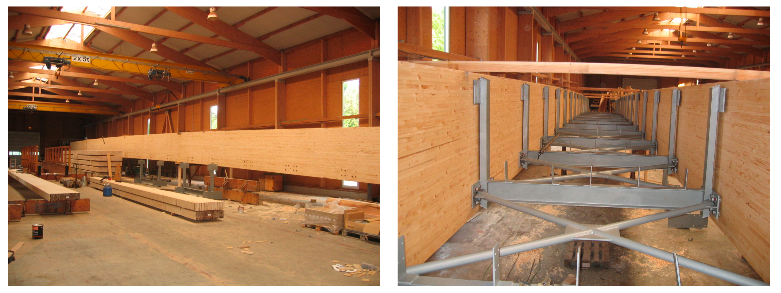
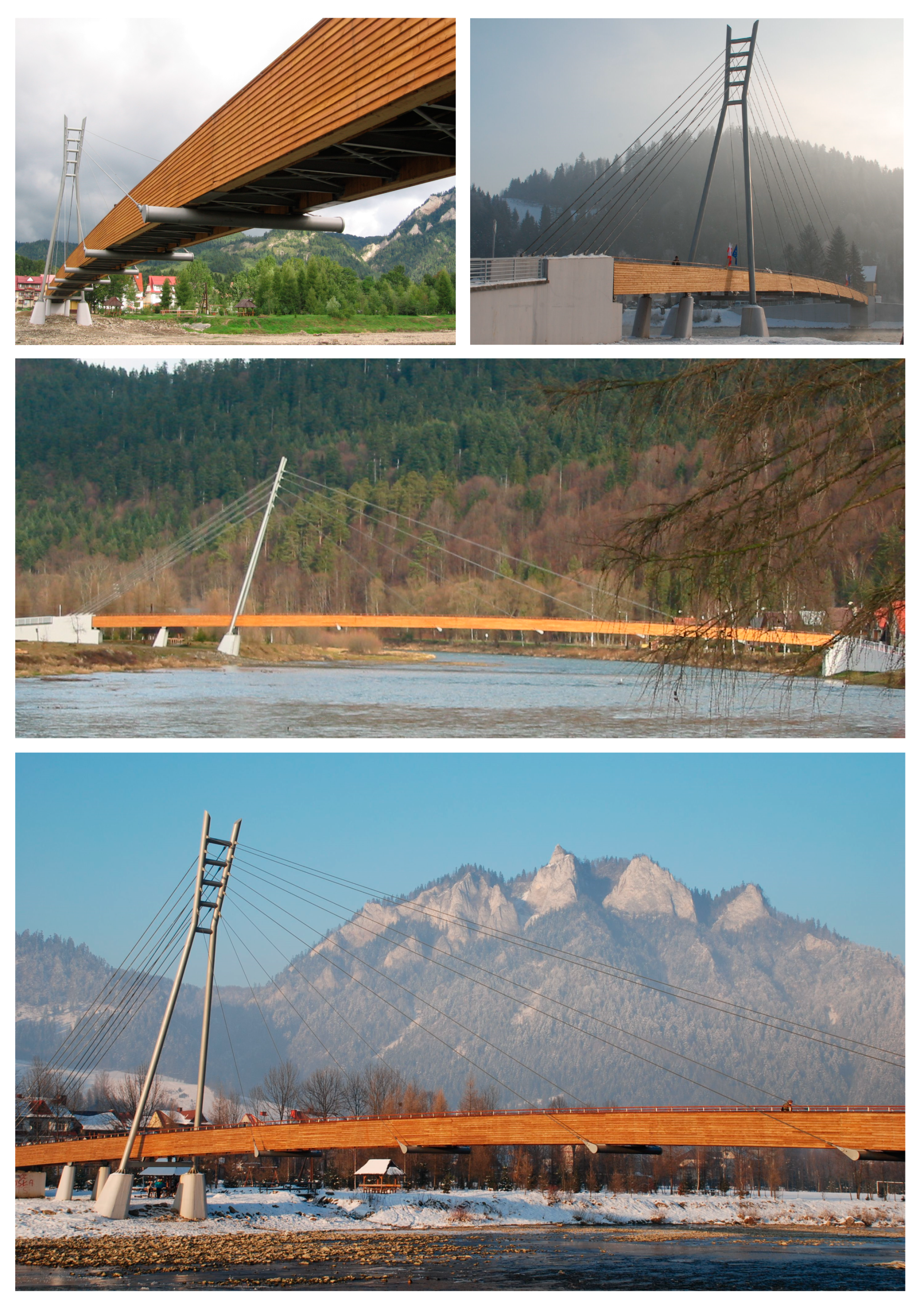
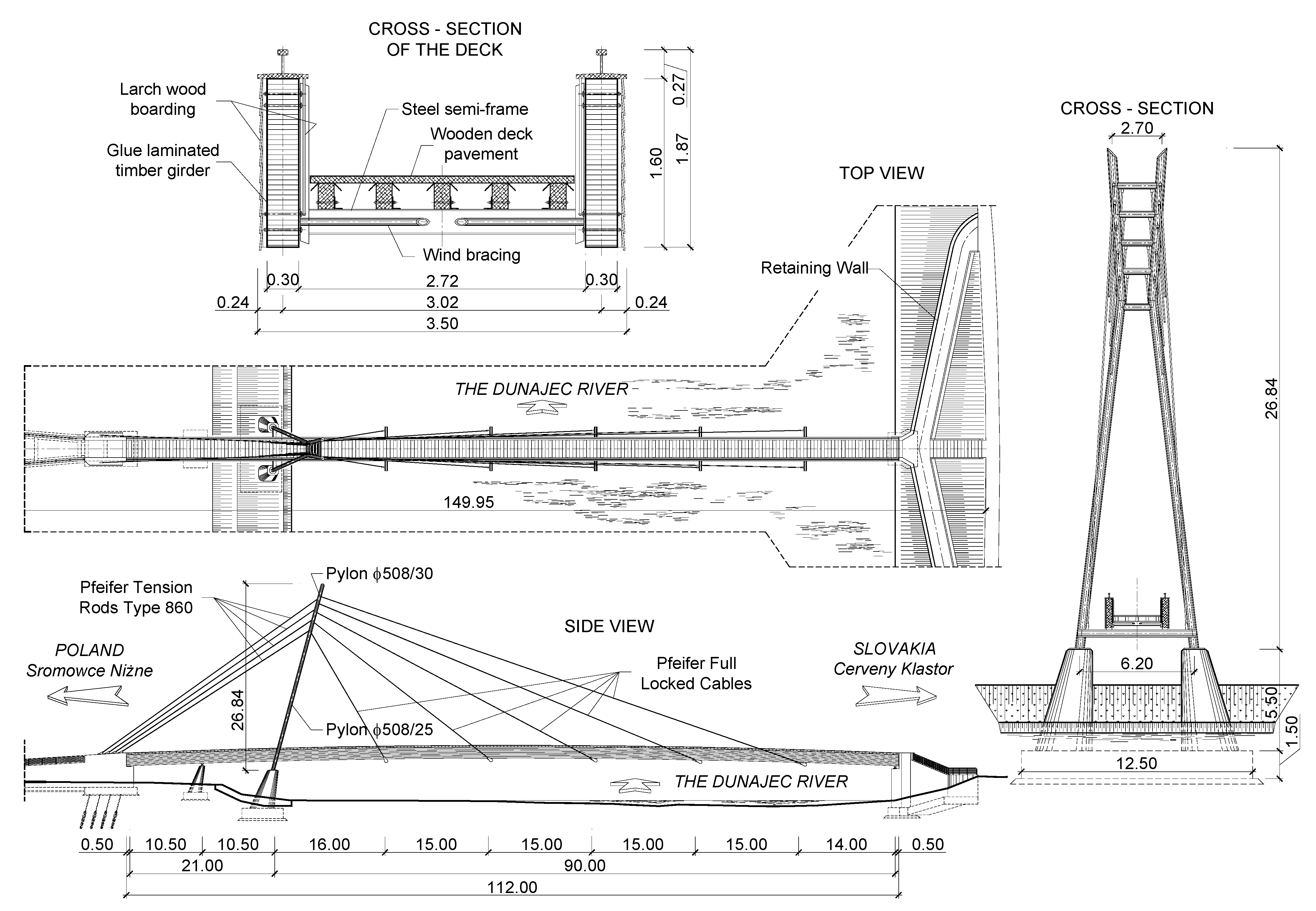
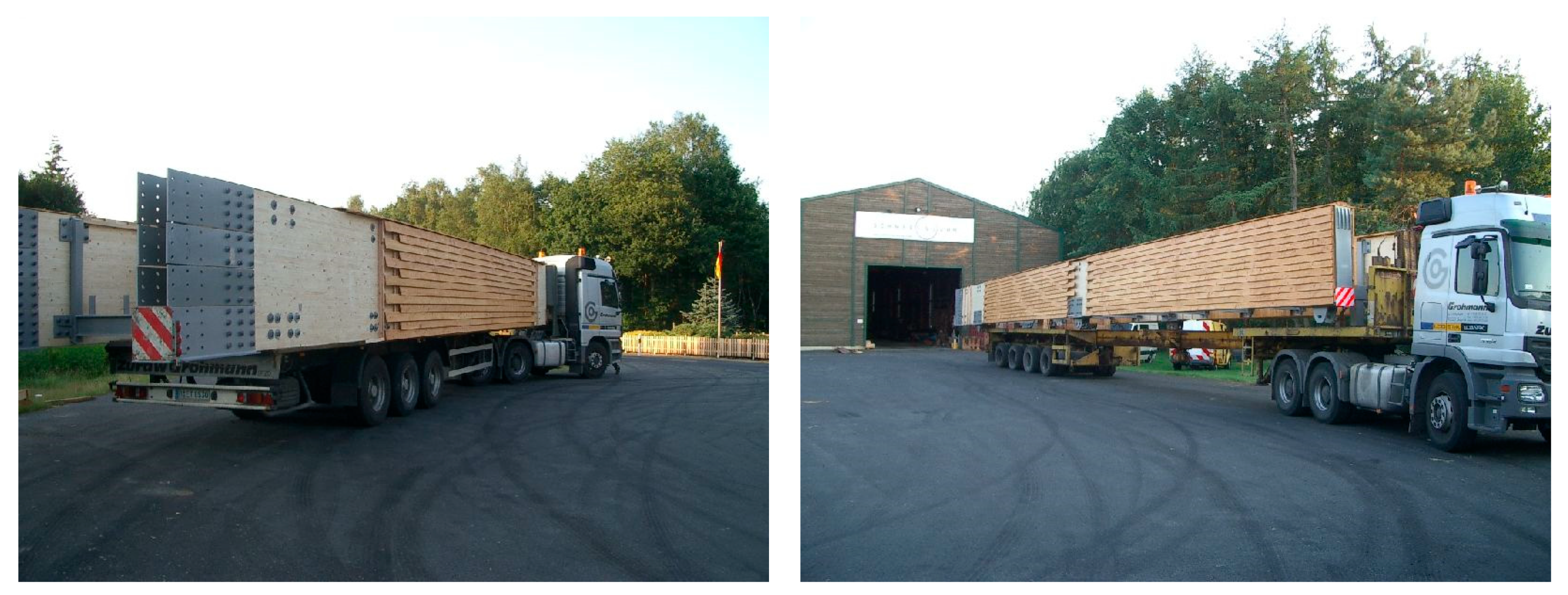
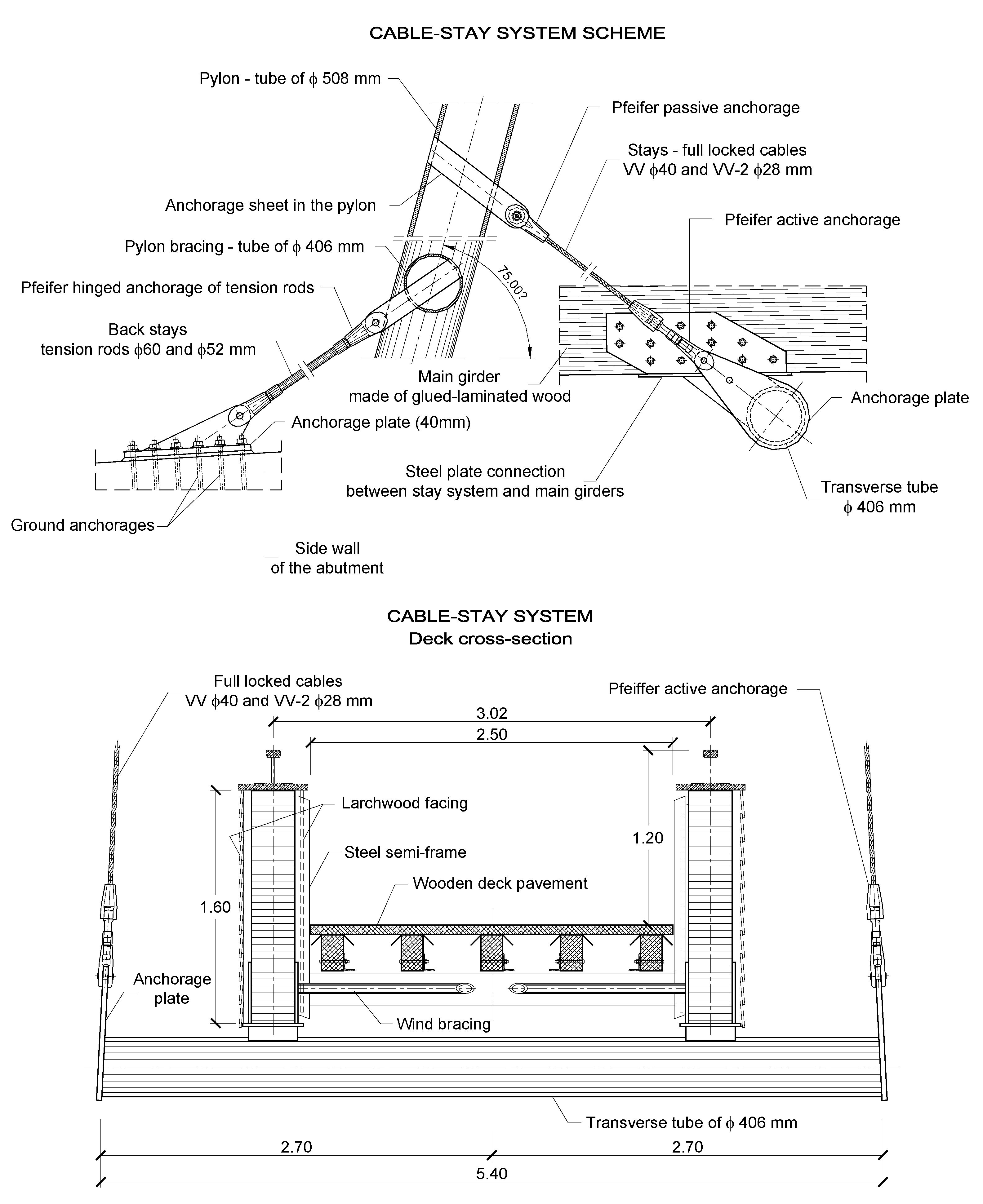
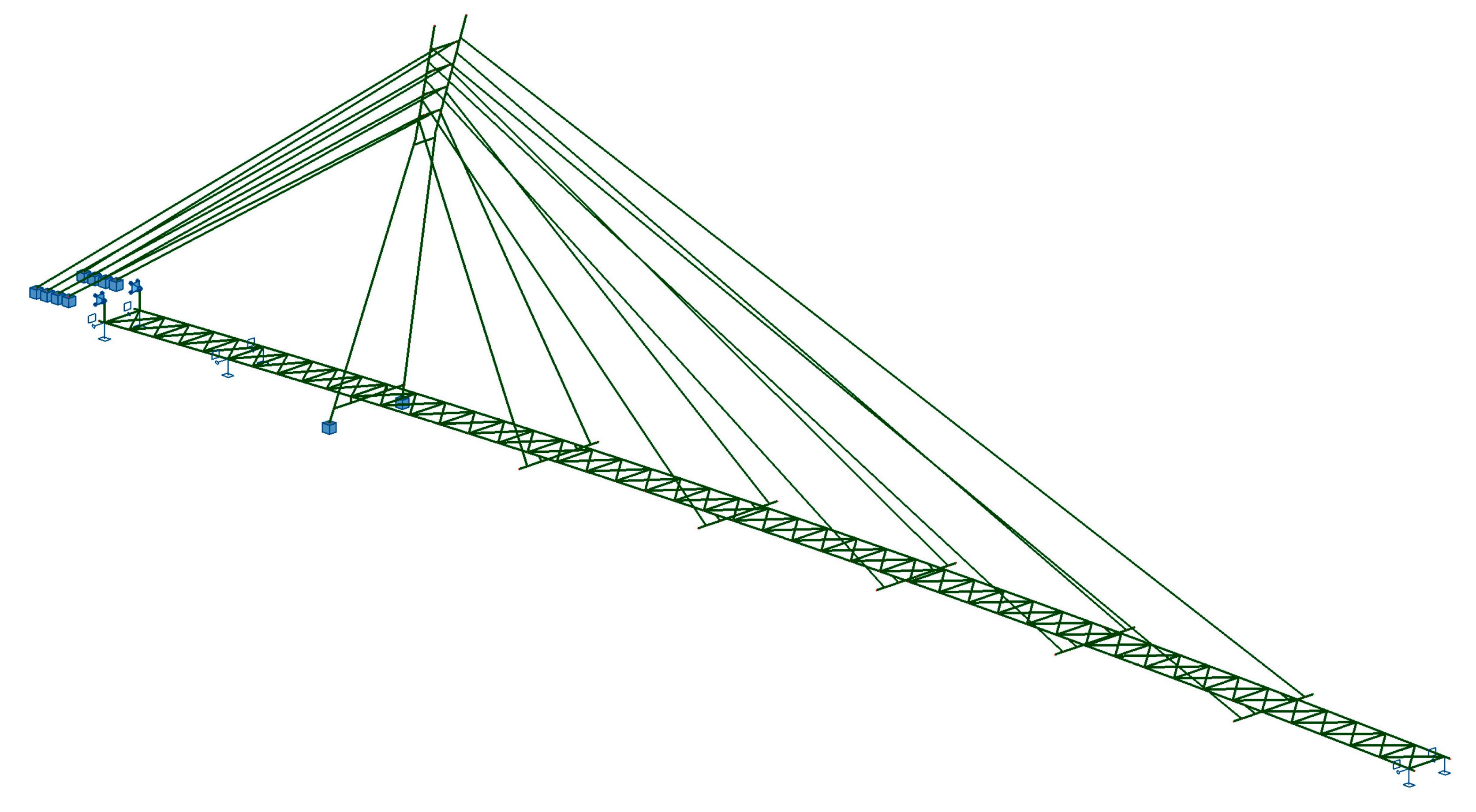
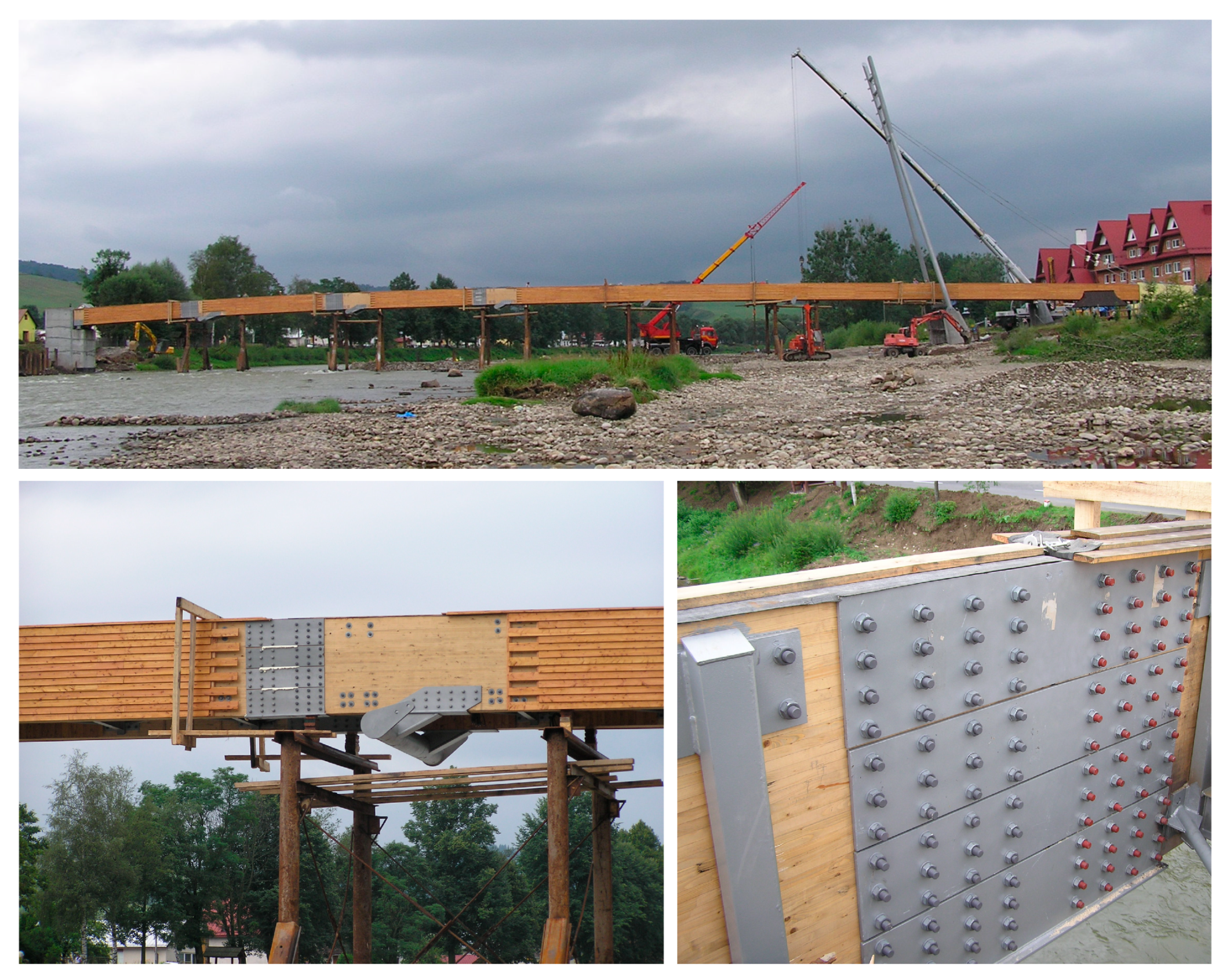
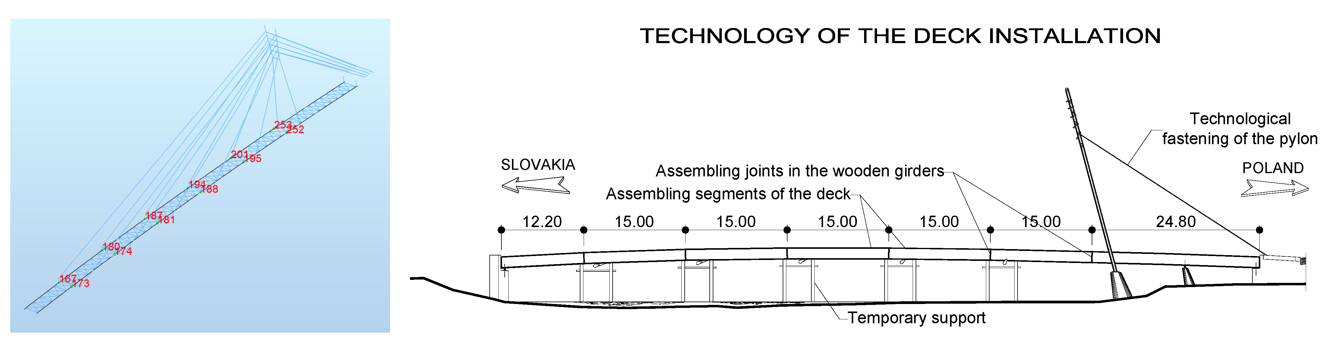
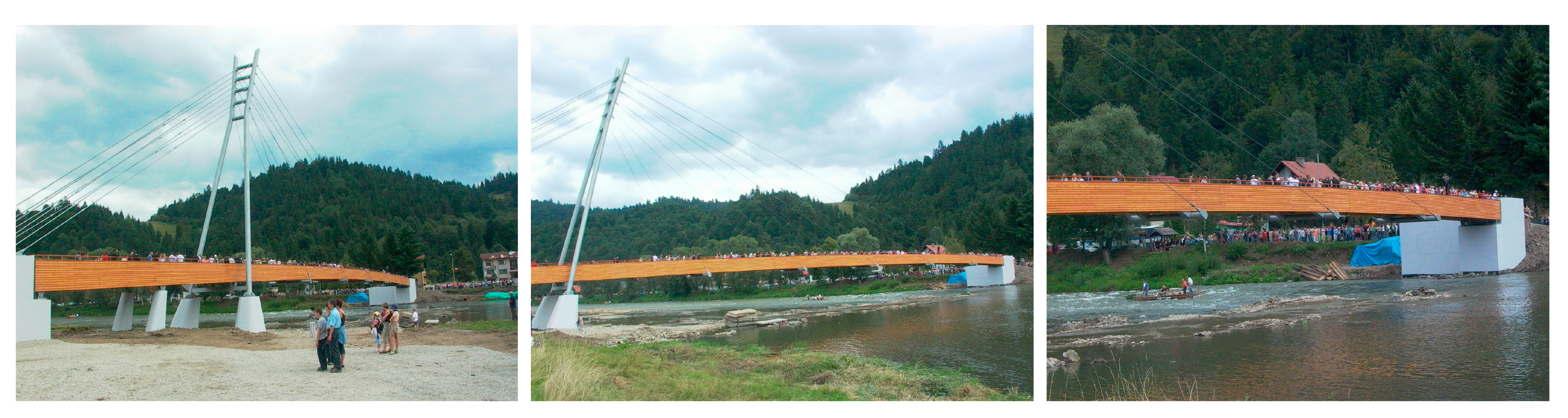
2.1. Cable-Stayed Structure
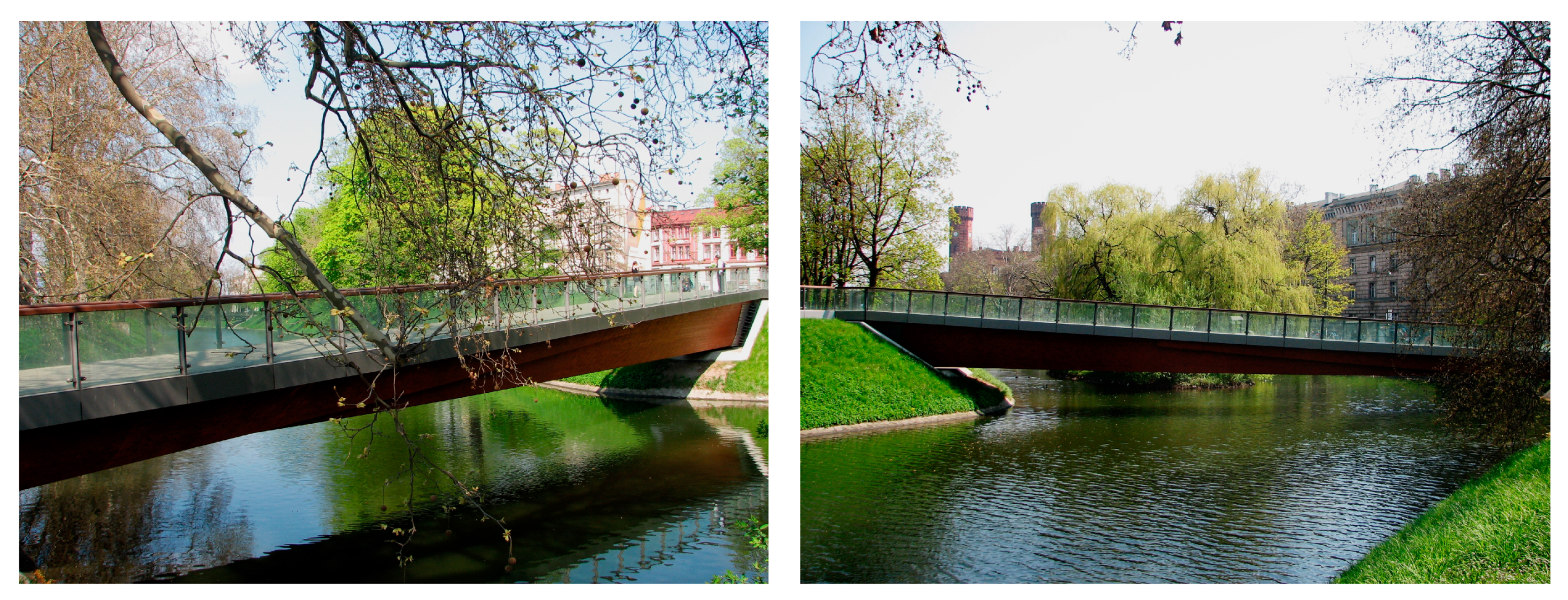
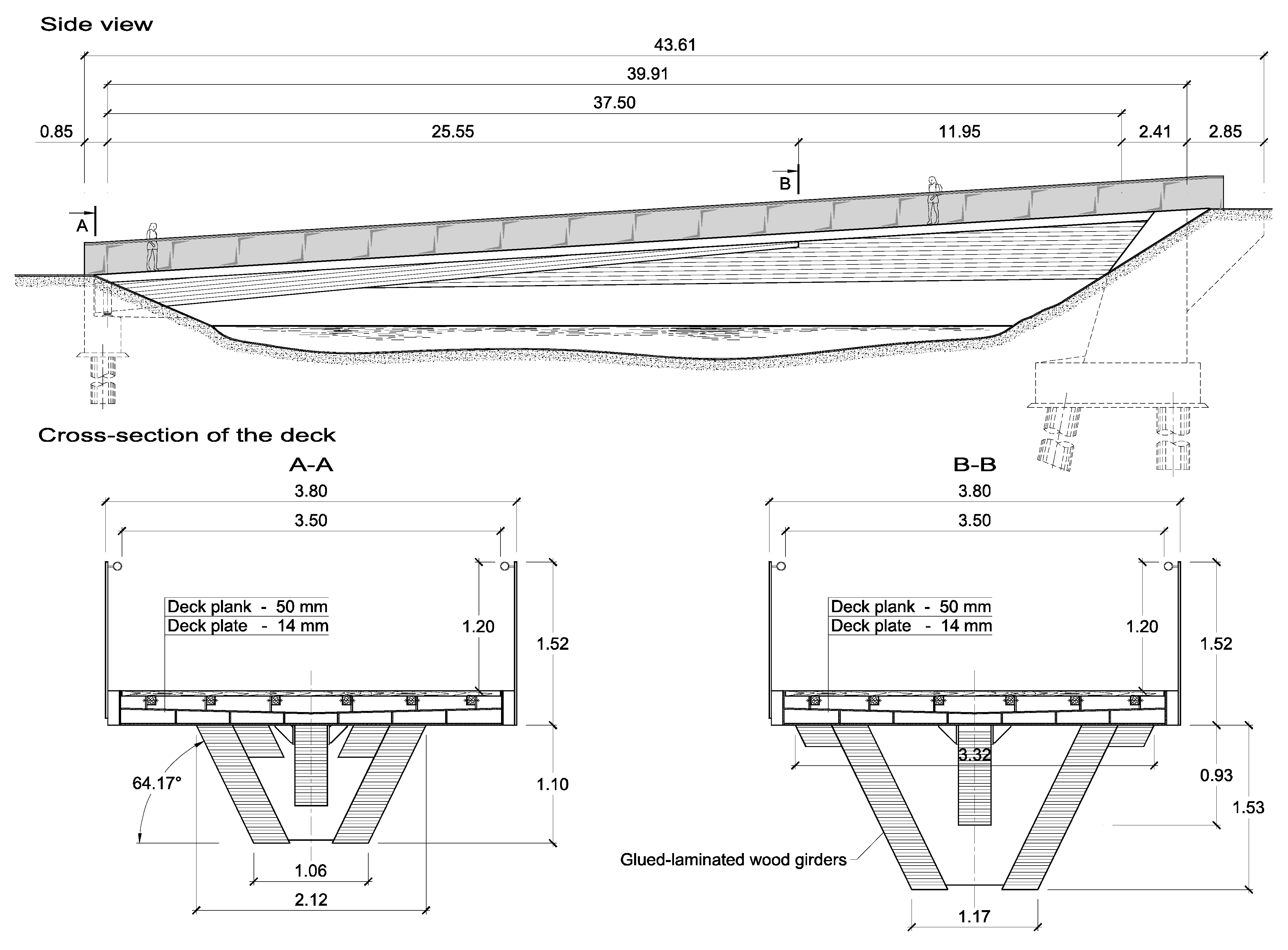
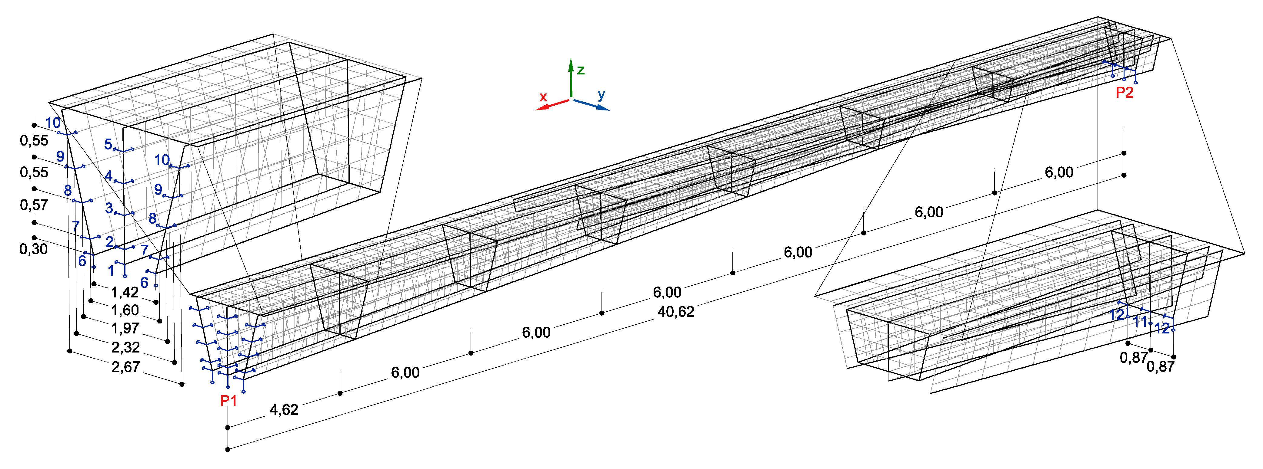
2.2. Beam Structure
3. Results
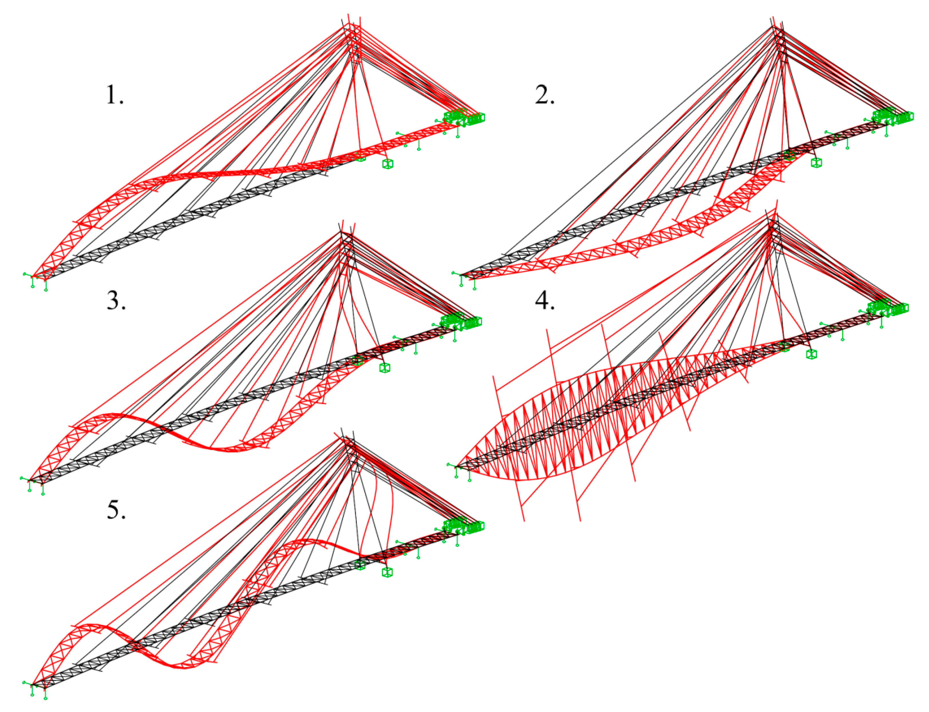
3.1. Dynamic Analysis of the Cable-Stayed Structure
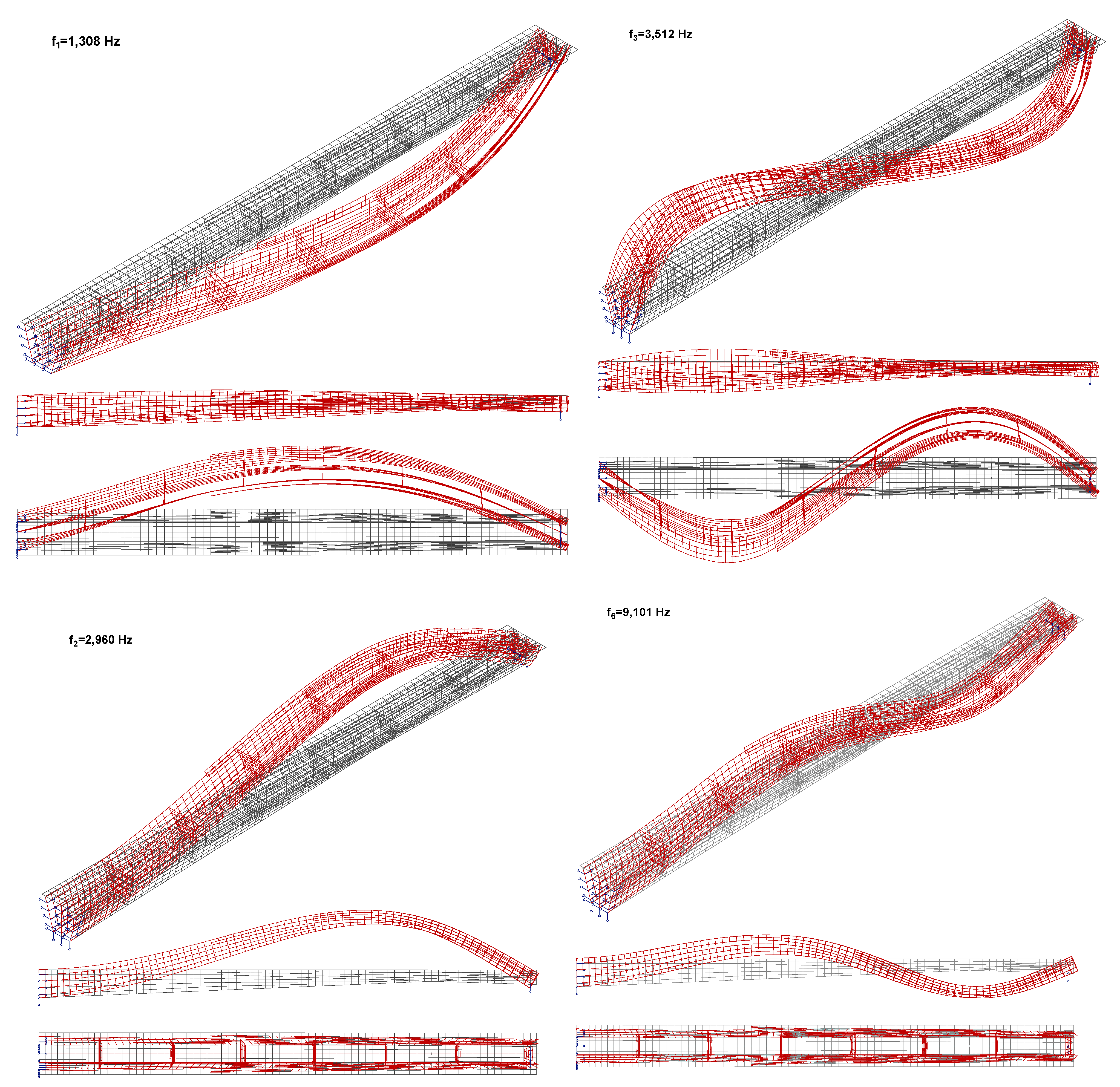
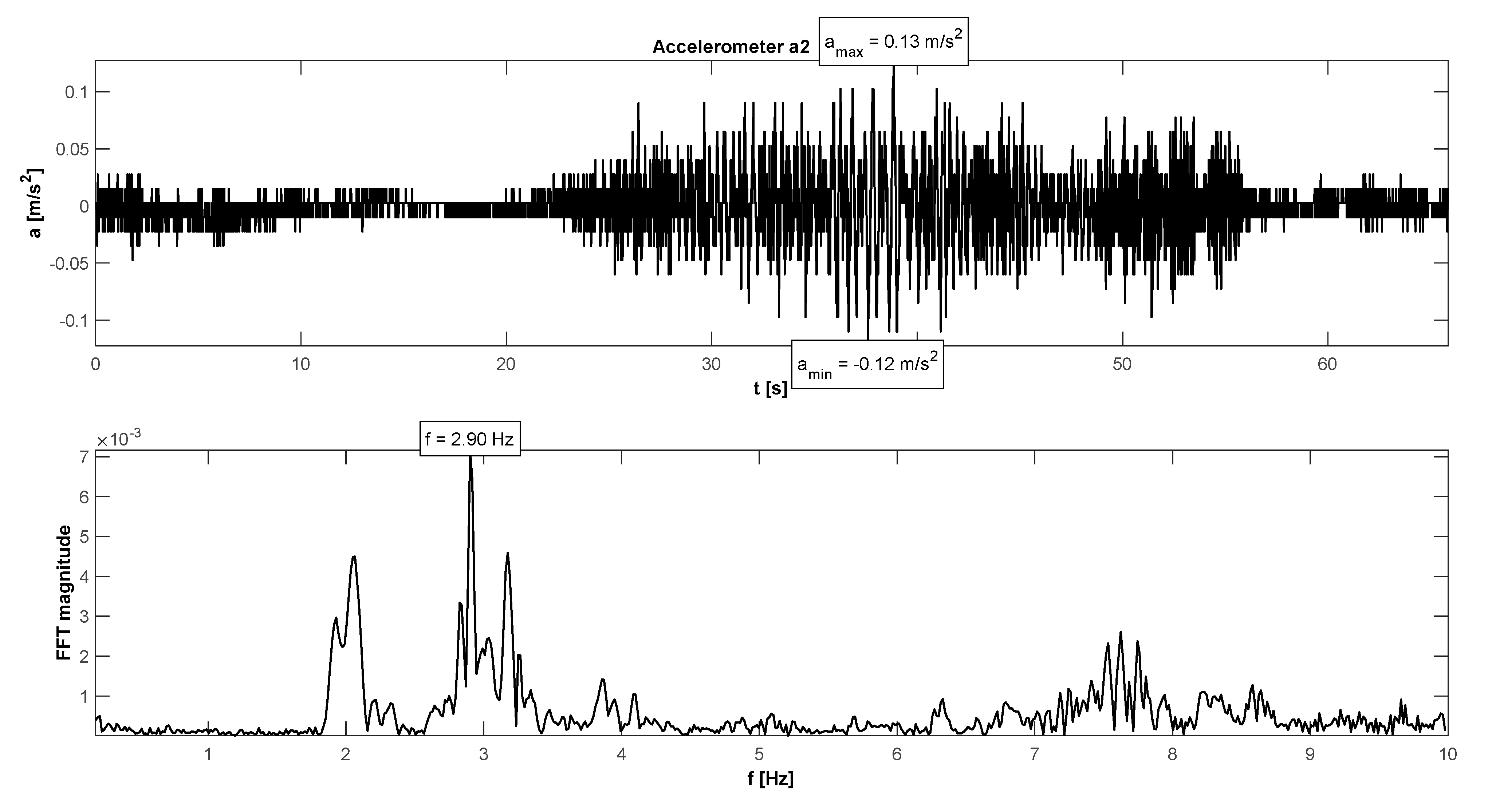
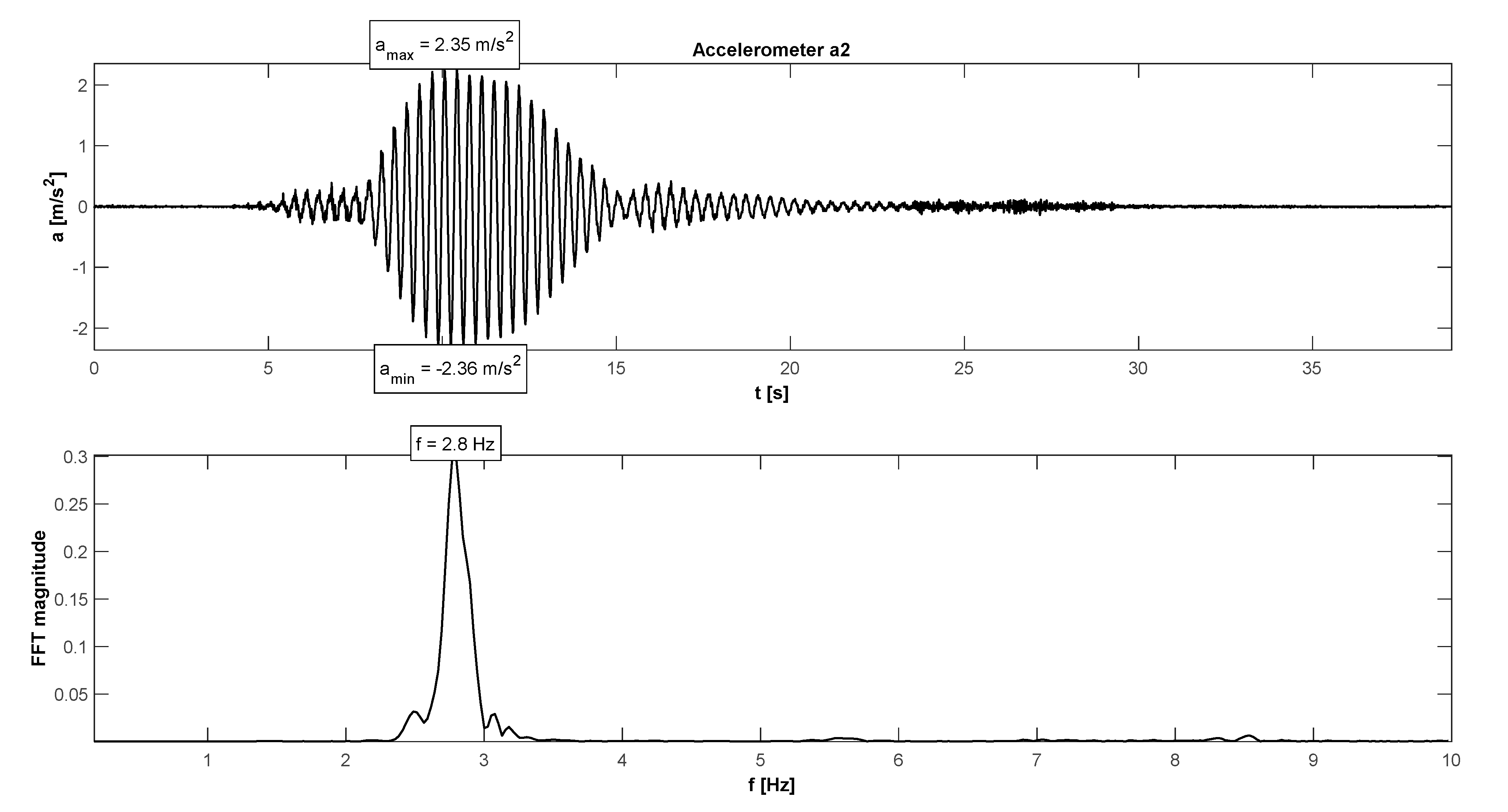
3.2. Dynamic Analysis of the Beam Structure
4. Discussion
5. Conclusions
Author Contributions
Funding
Institutional Review Board Statement
Informed Consent Statement
Data Availability Statement
Acknowledgments
Conflicts of Interest
References
- McRobie, A.; Morgenthal, G.; Lasenby, J.; Ringer, M. Section model tests on human—Structure lock-in. Proc. Inst. Civ. Eng.-Bridg. Eng. 2003, 156, 71–79. [Google Scholar] [CrossRef]
- Hu, W.-H.; Moutinho, C.; Caetano, E.; Magalhães, F.; Cunha. Continuous dynamic monitoring of a lively footbridge for serviceability assessment and damage detection. Mech. Syst. Signal Process. 2012, 33, 38–55. [Google Scholar] [CrossRef]
- Pimentel, R.; Viero, P.F.; Roitman, N.; Magluta, C.; Brito, J.L.V.; Doz, G.N.; Ávila, S.M.; Barbosa, F.S. Loads due to groups for vibration serviceability of footbridges. In Proceedings of the 4th International Conference Experimental Vibration Analysis for Civil Engineering Structures, EVACES 2011, Varenna, Italy, 3–5 October 2011. [Google Scholar]
- Żółtowski, K. Footbridge Vibration Design. In Footbridges, Numerical Approach; Caetano, E., Cunha, Á., Hoorpah, W., Raoul, J., Eds.; CRC Press, Taylor & Francis Group: London, UK, 2009. [Google Scholar]
- Hawryszków, P.; Pimentel, R.; Silva, R.; Silva, F. Vertical Vibrations of Footbridges Due to Group Loading: Effect of Pedestrian–Structure Interaction. Appl. Sci. 2021, 11, 1355. [Google Scholar] [CrossRef]
- Hawryszków, P.; Pimentel, R.; Silva, F. Vibration effects of loads due to groups crossing a lively footbridge. Procedia Eng. 2017, 199, 2808–2813. [Google Scholar] [CrossRef]
- Bocian, M.; Brownjohn, J.; Racic, V.; Hester, D.; Quattrone, A.; Gilbert, L.; Beasley, R. Time-dependent spectral analysis of interactions within groups of walking pedestrians and vertical structural motion using wavelets. Mech. Syst. Signal Process. 2018, 105, 502–523. [Google Scholar] [CrossRef]
- Pańtak, M. Ground Reaction Forces Generated by Runners—Harmonic Analyses and Modelling. Appl. Sci. 2020, 10, 1575. [Google Scholar] [CrossRef] [Green Version]
- Van Nimmen, K.; Broeck, P.V.D.; Lombaert, G.; Tubino, F. Pedestrian-Induced Vibrations of Footbridges: An Extended Spectral Approach. J. Bridg. Eng. 2020, 25, 04020058. [Google Scholar] [CrossRef]
- Drygala, I.J.; Dulinska, J.M. Full-Scale Experimental and Numerical Investigations on the Modal Parameters of a Single-Span Steel-Frame Footbridge. Symmetry 2019, 11, 404. [Google Scholar] [CrossRef] [Green Version]
- Banaś, A.; Jankowski, R. Experimental and Numerical Study on Dynamics of Two Footbridges with Different Shapes of Girders. Appl. Sci. 2020, 10, 4505. [Google Scholar] [CrossRef]
- Drygala, I.J.; Dulinska, J.M.; Ciura, R.; Lachawiec, K. Vibration Serviceability of Footbridges: Classical vs. Innovative Material Solutions for Deck Slabs. Materials 2020, 13, 3009. [Google Scholar] [CrossRef] [PubMed]
- Rizzo, F. Aeroelastic Response of Suspended Pedestrian Bridges Made of Laminated Wood and Hemp. Infrastructures 2020, 5, 60. [Google Scholar] [CrossRef]
- Kromoser, B.; Ritt, M.; Spitzer, A.; Stangl, R.; Idam, F. Design Concept for a Greened Timber Truss Bridge in City Area. Sustainability 2020, 12, 3218. [Google Scholar] [CrossRef] [Green Version]
- Vivas, J.; Santos, J.C. Sustainable Building: High Performance Timber Bridges. Proceedings 2018, 2, 1426. [Google Scholar] [CrossRef] [Green Version]
- Fiore, A.; Liuzzi, M.A.; Greco, R. Some Shape, Durability and Structural Strategies at the Conceptual Design Stage to Improve the Service Life of a Timber Bridge for Pedestrians. Appl. Sci. 2020, 10, 2023. [Google Scholar] [CrossRef] [Green Version]
- Dacol, V.; Caetano, E.; Correia, J. Comparative Study of Damping on Pultruded GFRP and Steel Beams. Polymers 2021, 13, 2201. [Google Scholar] [CrossRef] [PubMed]
- Mirski, R.; Dziurka, D.; Chuda-Kowalska, M.; Kawalerczyk, J.; Kuliński, M.; Łabęda, K. The Usefulness of Pine Timber (Pinus sylvestris L.) for the Production of Structural Elements. Part II: Strength Properties of Glued Laminated Timber. Materials 2020, 13, 4029. [Google Scholar] [CrossRef] [PubMed]
- Biliszczuk, J.; Hawryszków, P. Foot and cycling bridge over the Dunajec River in Sromowce Niżne. In Engineering Structures; ČKAIT: Prague, Czech Republic, 2012; pp. 136–143. [Google Scholar]
- Biliszczuk, J.; Hawryszków, P.; Sułkowski, M.; Maury, A. Cable-stayed footbridge made of glued-laminated wood erected in Sromowice Nizne, Poland. In Proceedings of the 3rd International Conference Footbridge 2008, Porto, Portugal, 2–4 July 2008. [Google Scholar]
- Biliszczuk, J.; Barcik, W.; Sułkowski, M.; Hawryszków, P.; Boniecki, T.; Styrylska, J. Conceptual design of a footbridge in the historical part of Wrocław. In Proceedings of the 3rd International Conference Footbridge 2008, Porto, Portugal, 2–4 July 2008. [Google Scholar]
- EN 1990; Eurocode 0. Basis of Structural Design. Annex A2: Application for Bridges. European Committee for Standardization: Brussels, Belgium, 1990.
- EN 1995-2; Eurocode 5. Design of Timber Structures—Part 2: Bridges. European Committee for Standardization: Brussels, Belgium, 1995.
- NBCC 1995; National Building Code of Canada. Commentary A: Serviceability Criteria for Deflections and Vibrations. NRCC: Ottawa, ON, Canada, 1995.
- BS 5400-2:1978; British Standard. Steel, Concrete and Composite Bridges—Part 2: Specification for Loads. Appendix C: Vibration Serviceability Requirements for Foot and Cycle Track Bridges. Steel and Concrete Bridges Standards Committee: London, UK, 1978.
- European Commission. HIVOSS—Human Induced Vibrations of Steel Structures. Design of Footbridges Guideline. Research Fund for Coal & Steel; European Commission: Brussels, Belgium, 2008. [Google Scholar]
- SÉTRA—Service d’Études Techniques des Routes et Autoroutes. Technical Guide Footbridges—Assessment of Vibrational Behaviour of Footbridges under Pedestrian Loading; Association Française de Génie Civil: Paris, France, 2006. [Google Scholar]
- Hawryszków, P. Assessment of pedestrian comfort and safety of footbridges in dynamic conditions: Case study of a landmark arch footbridge. Builder 2021, 286, 78–82. [Google Scholar] [CrossRef]
- Banaś, A. Assessment of pedestrian comfort on footbridges. Case study. Builder 2020, 277, 26–31. [Google Scholar] [CrossRef]
- Hawryszków, P. Analysis of dynamical sensitivity and comfort of footbridges. In Proceedings of the 4th International Conference Footbridge 2011, Wrocław, Poland, 6–8 July 2011; pp. 1037–1046. [Google Scholar]
- Sadowski, K.; Hawryszków, P.; Barcik, W. Project of Proof-Load Tests of the Footbridge over the Moat in Wrocław; Research Report; No. U-8/2009; Wrocław University of Technology: Wrocław, Poland, 2009. (In Polish) [Google Scholar]
- Sadowski, K.; Hawryszków, P. Proof-Load Tests of the Footbridge over the Moat in Wrocław; Research Report; No. U-54/2009; Wrocław University of Technology: Wrocław, Poland, 2009. (In Polish) [Google Scholar]
- EN 1991-1-4; Eurocode 1. Actions on Structures—Part 1–4: General Actions—Wind Actions. Annex F: Dynamic Characteristics of Structures. European Committee for Standardization: Brussels, Belgium, 1991.
- Twenty Most Interesting Objects for Tourism and Recreation—Subjective Guide. Archit.-Murator 2017, 6. Available online: https://architektura.muratorplus.pl/krytyka/20-najciekawszych-obiektow-sluzacych-turystyce-i-rekreacji-subiektywny-przewodnik-architektury-murat_7516.html (accessed on 30 January 2022). (In Polish).


| No. | Results of Investigation f [Hz] | Results of Calculation f [Hz] | Type of Vibrations |
|---|---|---|---|
| 1 | 1.22 | 1.35 | 1st vertical bending mode |
| 2 | 2.16 | 2.47 | 2nd vertical bending mode |
| 3 | 3.84 | 4.18 | 3rd vertical bending mode |
| 4 | 1.10 | 1.41 | 1st horizontal bending mode |
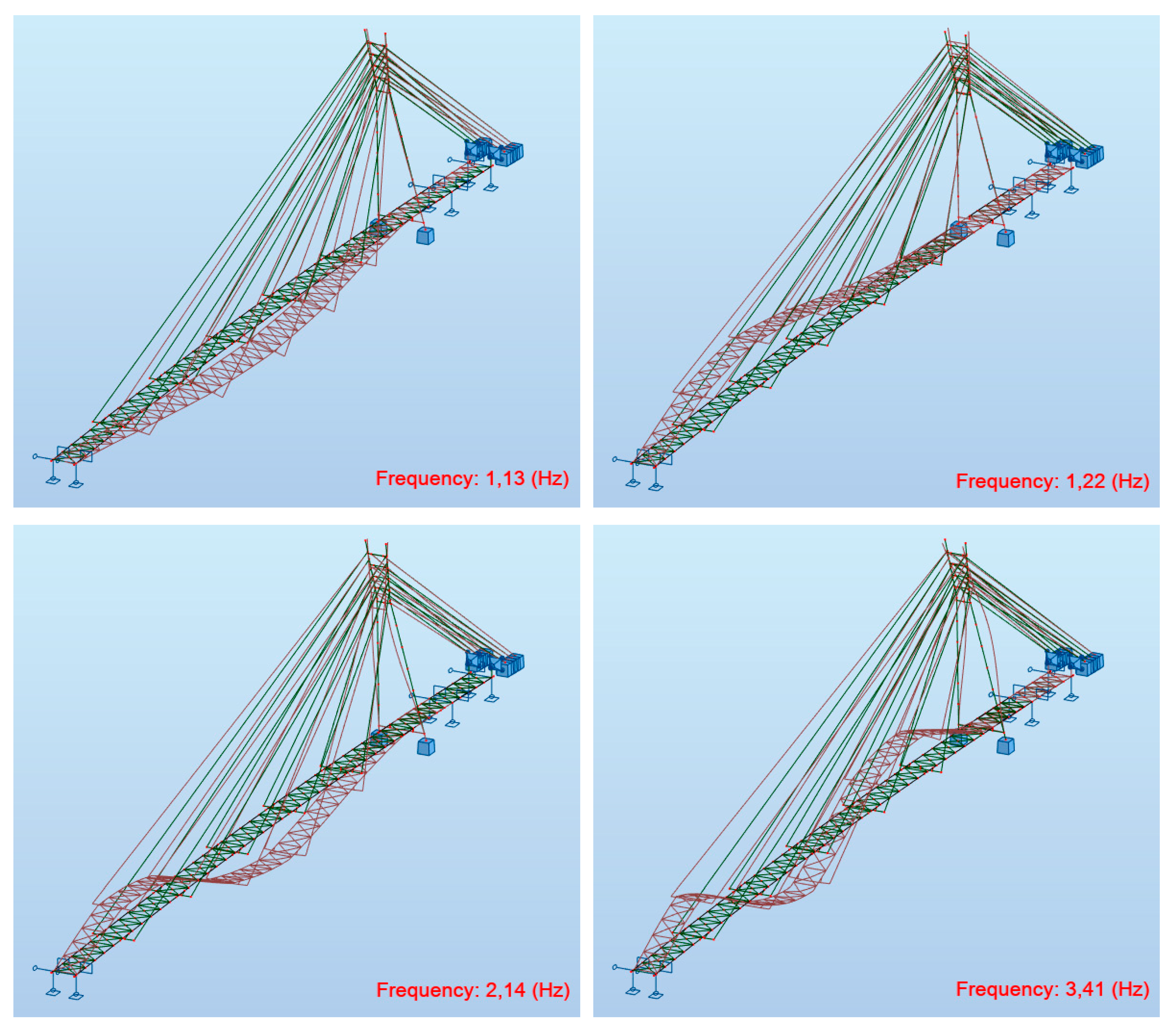
| No. | Results of Investigation Real Structure f [Hz] | Results of Calculation Updated FEM Model f [Hz] | Type of Vibrations |
|---|---|---|---|
| 1 | 1.22 | 1.22 | 1st vertical bending mode |
| 2 | 2.16 | 2.14 | 2nd vertical bending mode |
| 3 | 3.84 | 3.41 | 3rd vertical bending mode |
| 4 | 1.10 | 1.13 | 1st horizontal bending mode |
| No. | Original FEM Model | Updated FEM Model | ||
|---|---|---|---|---|
| f [Hz] | Type of Vibrations | f [Hz] | Type of Vibrations | |
| 1 | 1.35 | 1st vertical bending mode | 1.13 | 1st horizontal bending mode |
| 2 | 1.41 | 1st horizontal bending mode | 1.22 | 1st vertical bending mode |
| Test | No. of Pedestrians | amaxV [m/s2] | Comfort Criteria |
|---|---|---|---|
| Walking | 12 | 0.21 | Fulfilled |
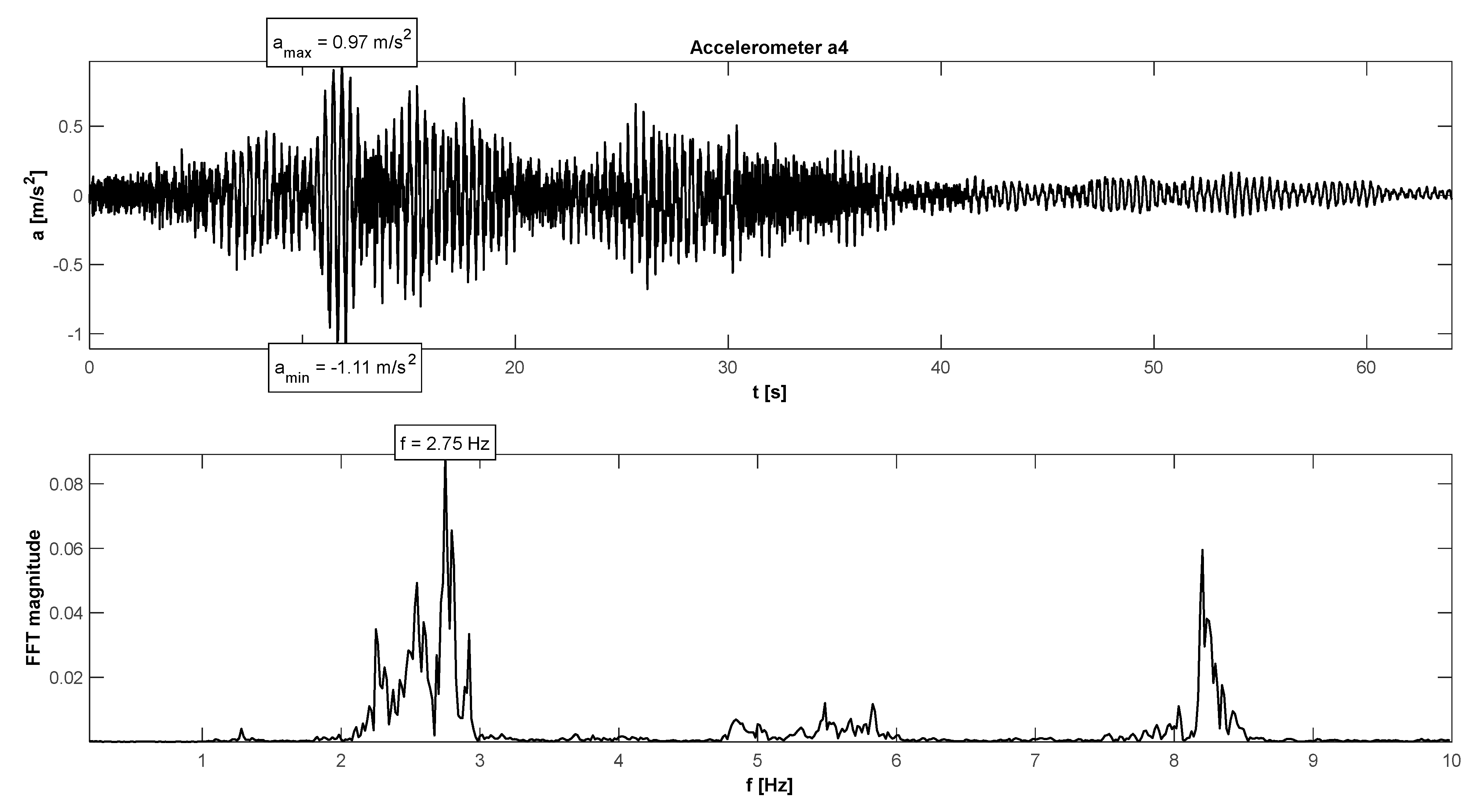
| Running | 12 | 1.11 | Fulfilled |
| Fast running | 12 | 1.38 | Fulfilled |
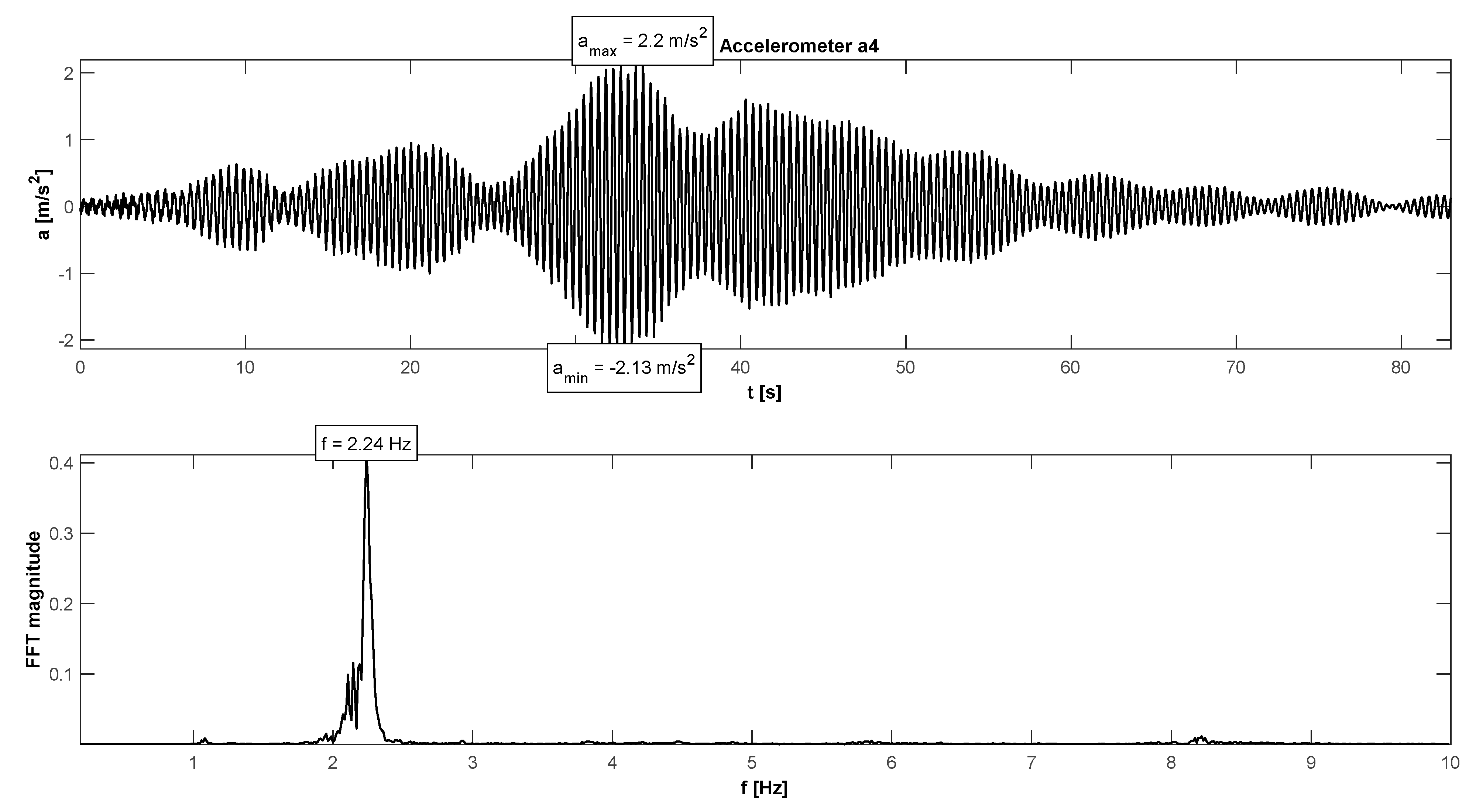
| Synchronized walking | 12 | 2.20 | - |
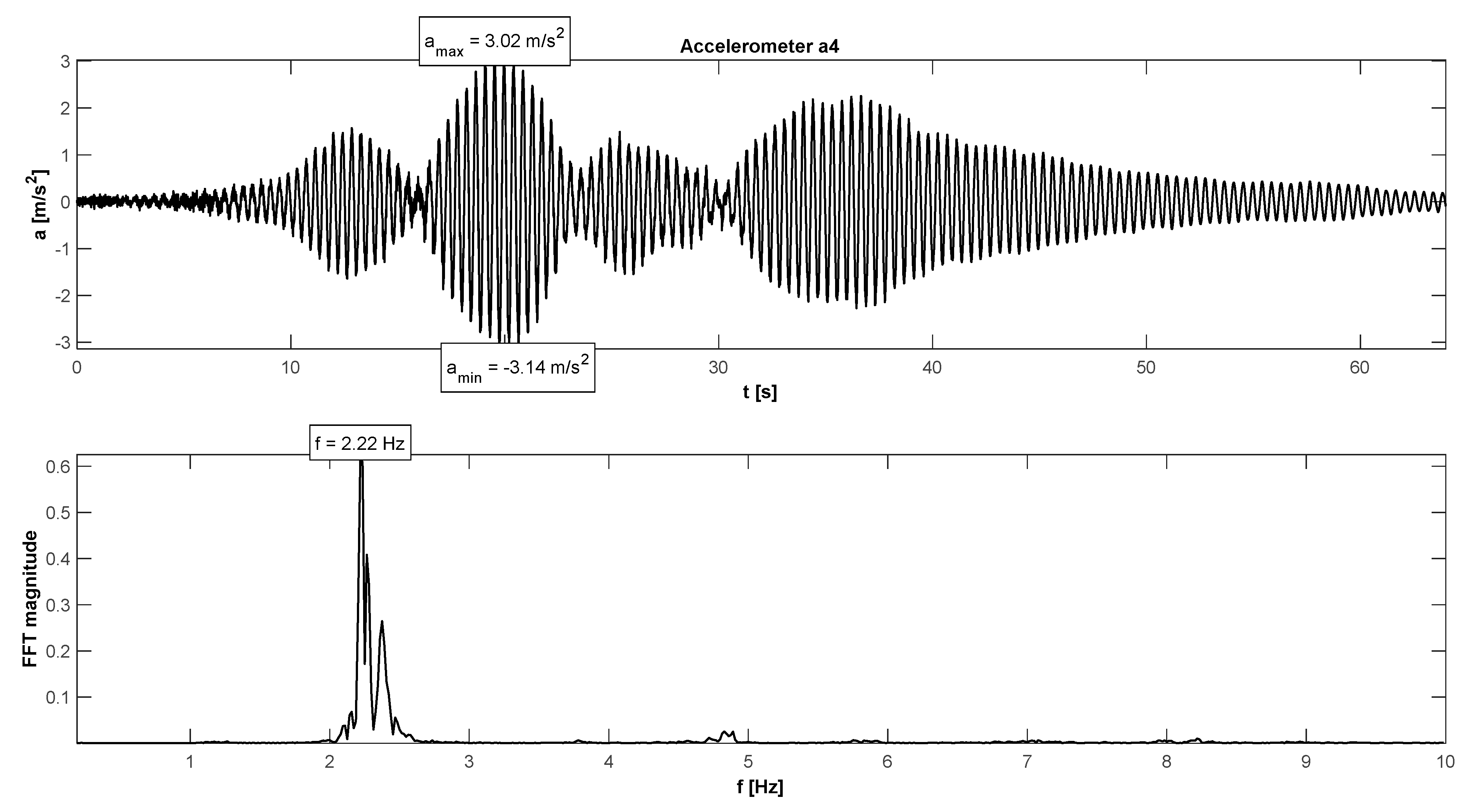
| Synchronized running | 12 | 3.14 | - |
| Synchronized half-crouching | 12 | 4.19 | - |
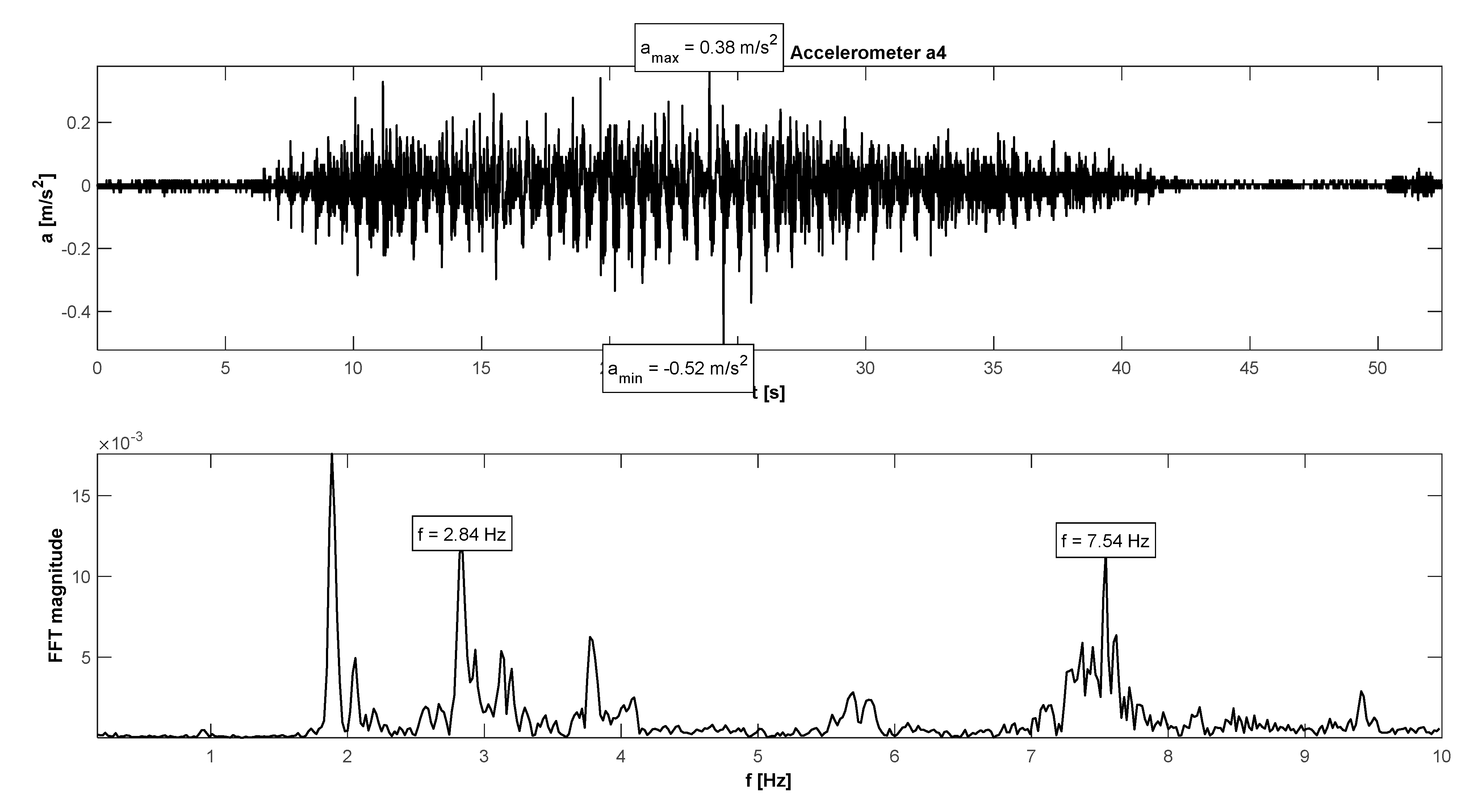
| No. | Results of Investigation f [Hz] | Results of Calculation f [Hz] | Type of Vibrations |
|---|---|---|---|
| 1 | 2.93 | 2.96 | 1st vertical bending mode |
| 2 | 7.38 | 9.10 | 2nd vertical bending mode |
| 3 | 2.63 | 1.31 | 1st horizontal bending mode |
| 4 | 3.23 | 3.51 | 2nd horizontal bending mode |
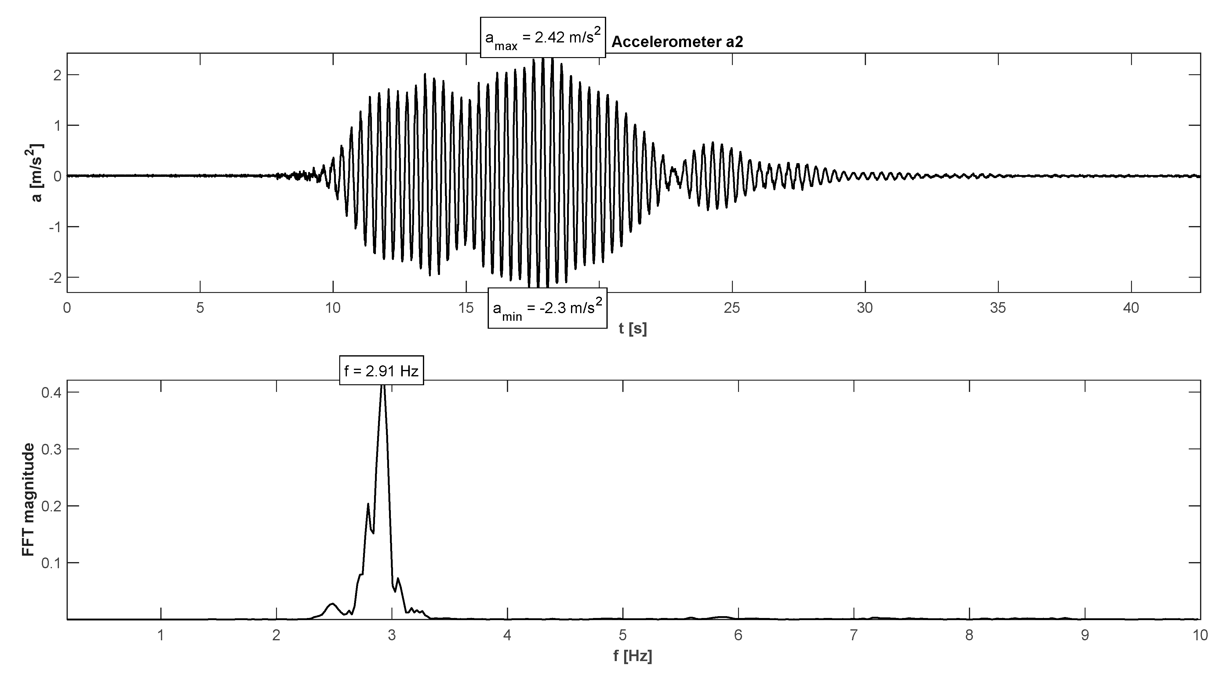
| Test | No. of Pedestrians | amaxV [m/s2] | Comfort Criteria |
|---|---|---|---|
| Walking | 10 | 0.13 | Fulfilled |
| Running | 10 | 2.36 | Exceeded |
| Fast running | 10 | 1.04 | Fulfilled |
| Synchronized walking | 10 | 0.52 | - |
| Synchronized running | 10 | 2.42 | - |
| Synchronized half-crouching | 10 | 2.75 | - |
| No. | Cable-Stayed Footbridge f [Hz] | Beam Footbridge f [Hz] | Type of Vibrations |
|---|---|---|---|
| 1 | 1.22 | 2.93 | 1st vertical bending mode |
| 2 | 2.16 | 7.38 | 2nd vertical bending mode |
| 3 | 1.10 | 2.63 | 1st horizontal bending mode |
| Test | Cable-Stayed Footbridge amaxV [m/s2] | Beam Footbridge amaxV [m/s2] |
|---|---|---|
| Walking | 0.21 | 0.13 |
| Running | 1.11 | 2.36 |
| Fast running | 1.38 | 1.04 |
| Synchronized walking | 2.20 | 0.52 |
| Synchronized running | 3.14 | 2.42 |
| Synchronized half-crouching | 4.19 | 2.75 |
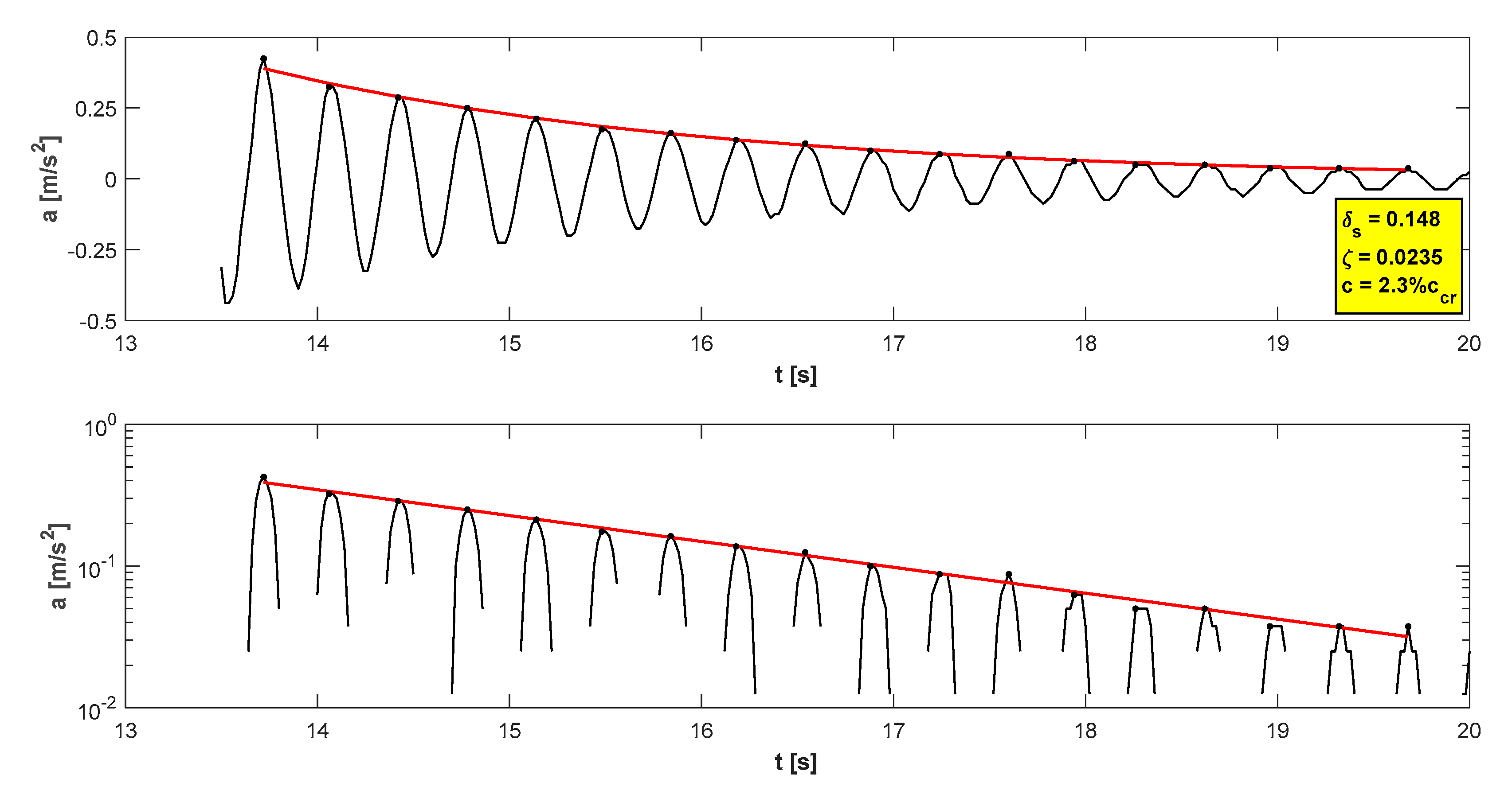
| Damping | Cable-Stayed Footbridge | Beam Footbridge |
|---|---|---|
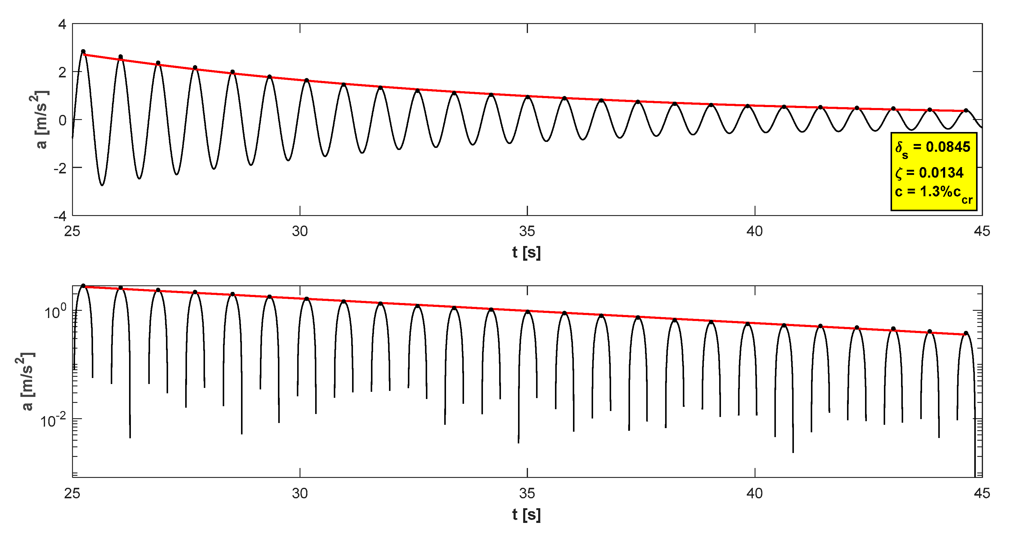
| Damping coefficientc [%] | 1.3ccr | 2.3ccr |
| Logarithmic decrement of structural damping δs [−] | 0.08 | 0.15 |
Publisher’s Note: MDPI stays neutral with regard to jurisdictional claims in published maps and institutional affiliations. |
© 2022 by the authors. Licensee MDPI, Basel, Switzerland. This article is an open access article distributed under the terms and conditions of the Creative Commons Attribution (CC BY) license (https://creativecommons.org/licenses/by/4.0/).
Share and Cite
Hawryszków, P.; Biliszczuk, J. Vibration Serviceability of Footbridges Made of the Sustainable and Eco Structural Material: Glued-Laminated Wood. Materials 2022, 15, 1529. https://doi.org/10.3390/ma15041529
Hawryszków P, Biliszczuk J. Vibration Serviceability of Footbridges Made of the Sustainable and Eco Structural Material: Glued-Laminated Wood. Materials. 2022; 15(4):1529. https://doi.org/10.3390/ma15041529
Chicago/Turabian StyleHawryszków, Paweł, and Jan Biliszczuk. 2022. "Vibration Serviceability of Footbridges Made of the Sustainable and Eco Structural Material: Glued-Laminated Wood" Materials 15, no. 4: 1529. https://doi.org/10.3390/ma15041529