
Analysis of Efficiency of Thermoelectric Personal Cooling System Based on Utility Tests


Abstract
:1. Introduction
2. Materials and Methods
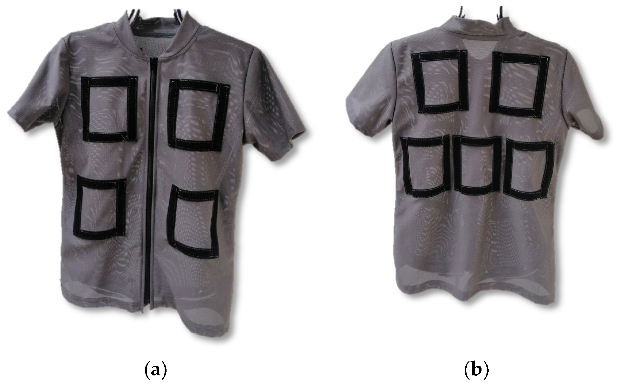
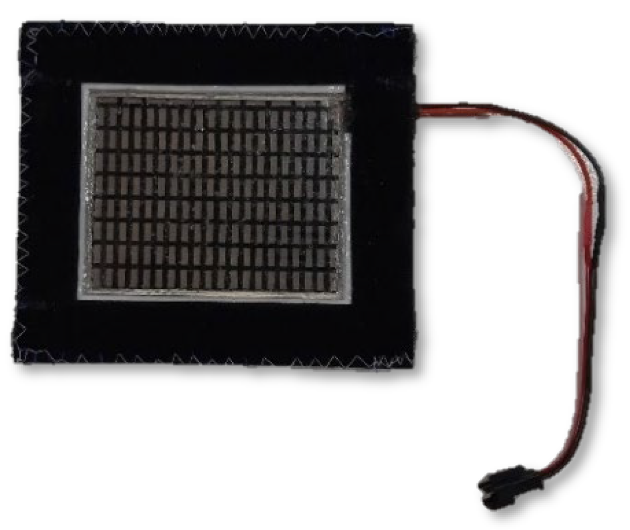
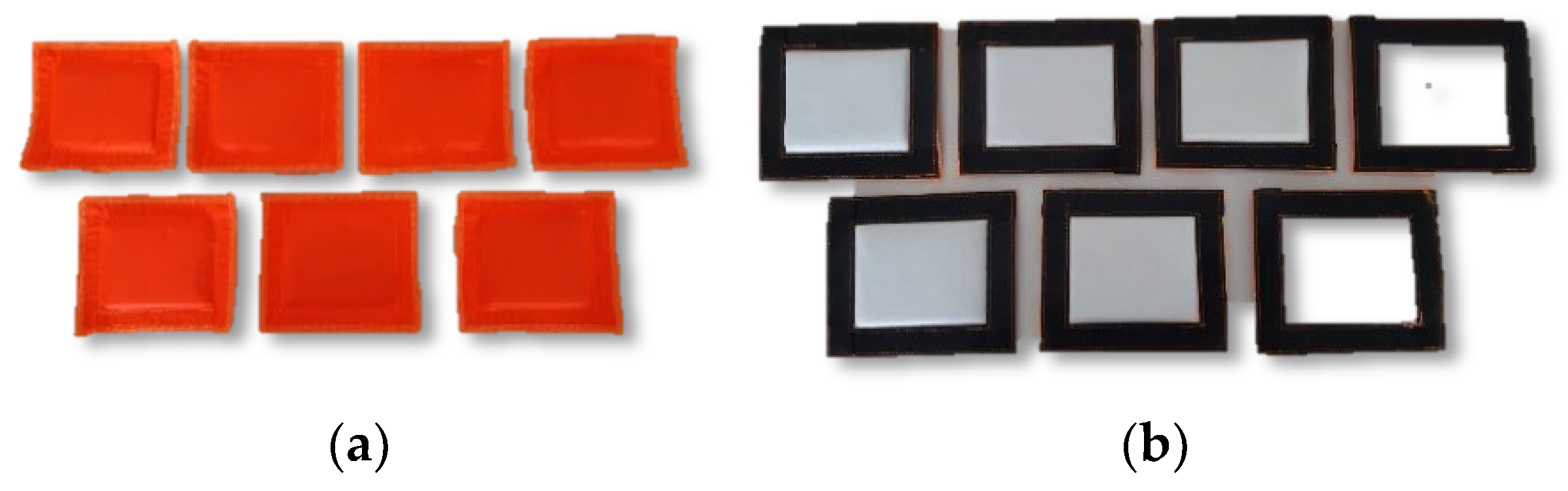
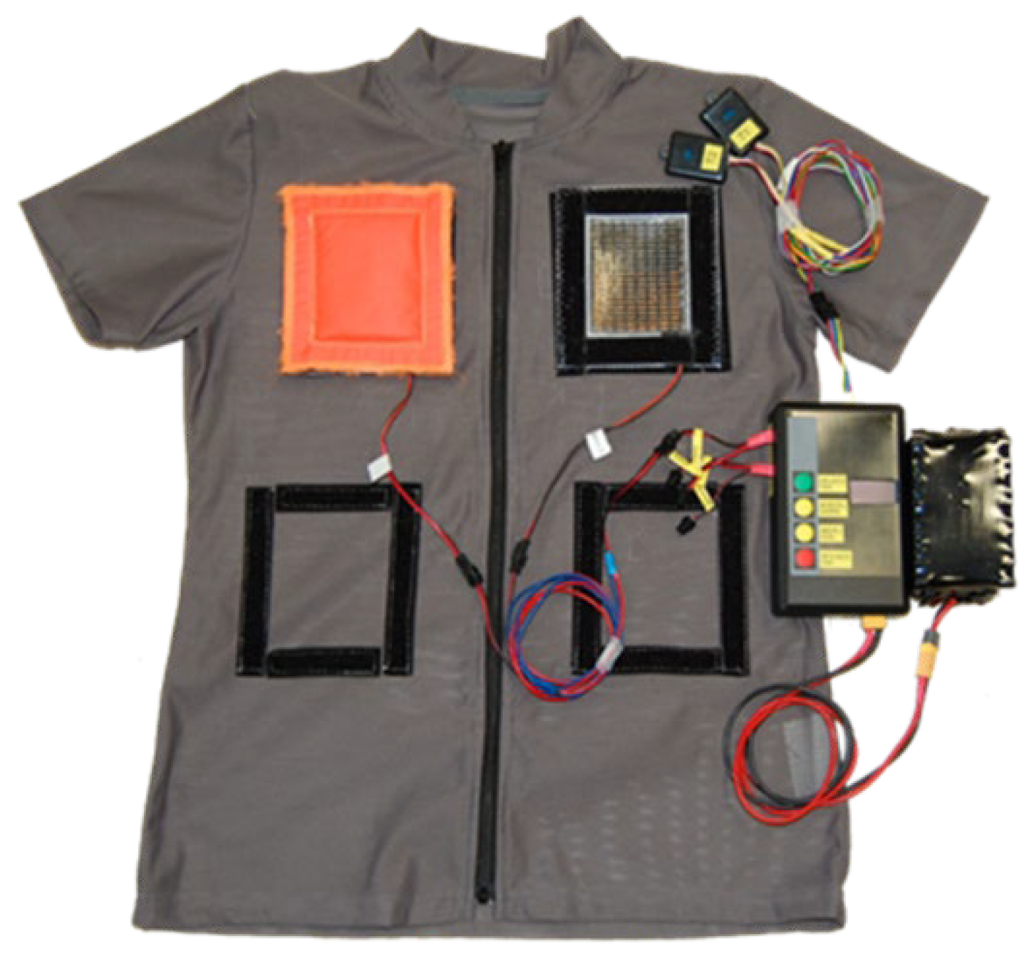
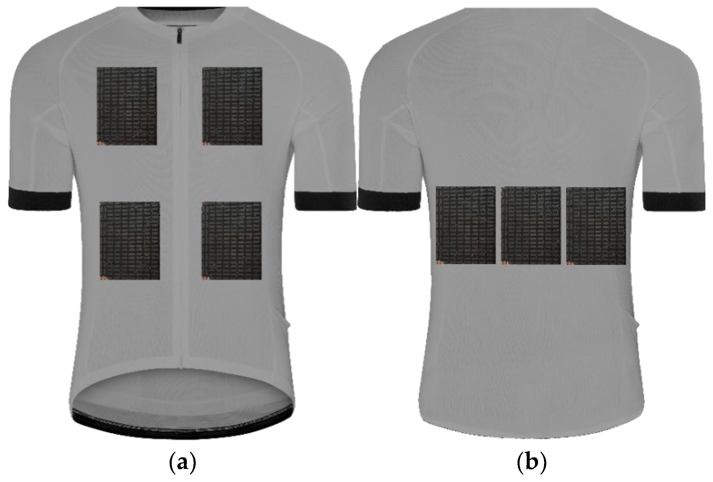
2.1. Tested Object
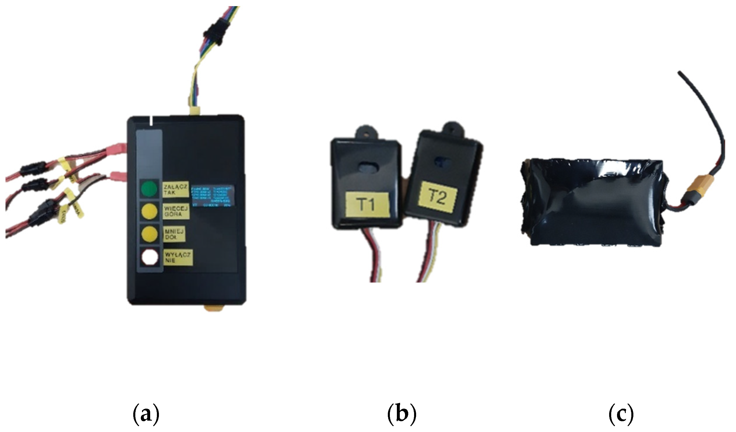
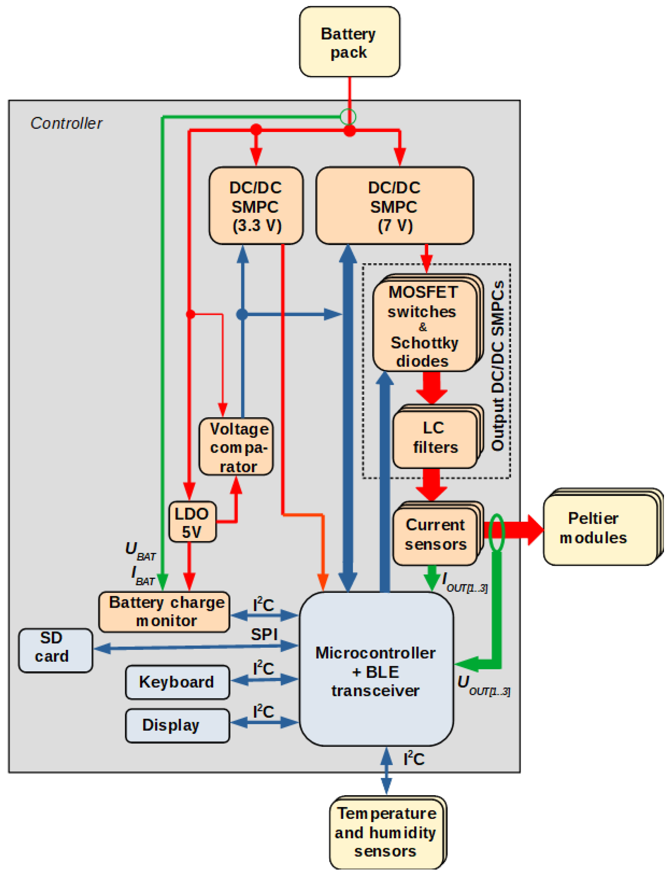
2.2. Structure and Operating Principle of the Dedicated Electronic Controller
- an auxiliary DC/DC switched-mode power converter (SMPC) with an integrated analog controller, to supply the control electronics;
- a main DC/DC SMPC with an integrated analog controller, to derive power for the TEC;
- three digitally controlled output DC/DC SMPCs (one per output channel), to supply the Peltier modules in each channel;
- current sensors (one per channel) in the form of shunt resistors with dedicated voltage amplifiers, to measure channel output currents;
- a battery charge monitor supplied from a separate low-drop-out (LDO) linear voltage regulator;
- a voltage comparator turning off the converters when the battery voltage becomes to low, thus protecting the battery from excessive discharge;
- a microcontroller with the Bluetooth Low Energy (BLE) radio interface;
- a four-button keyboard;
- an alphanumeric organic light emitting diode (OLED) display;
- a micro secure digital (SD) card interface for configuration and data storage.

2.3. Testing Methodology
2.3.1. Research Conditions
2.3.2. Measured Parameters
2.3.3. Research Procedure
- Activity I—walk at a speed of 3 km/h.
- Break.
- Activity II—walk at a speed of 5 km/h.
- Break.
- Activity III—walk at a speed of 5 km/h with a 10% inclination of the treadmill.
- Break.
2.3.4. Study Variants
3. Results
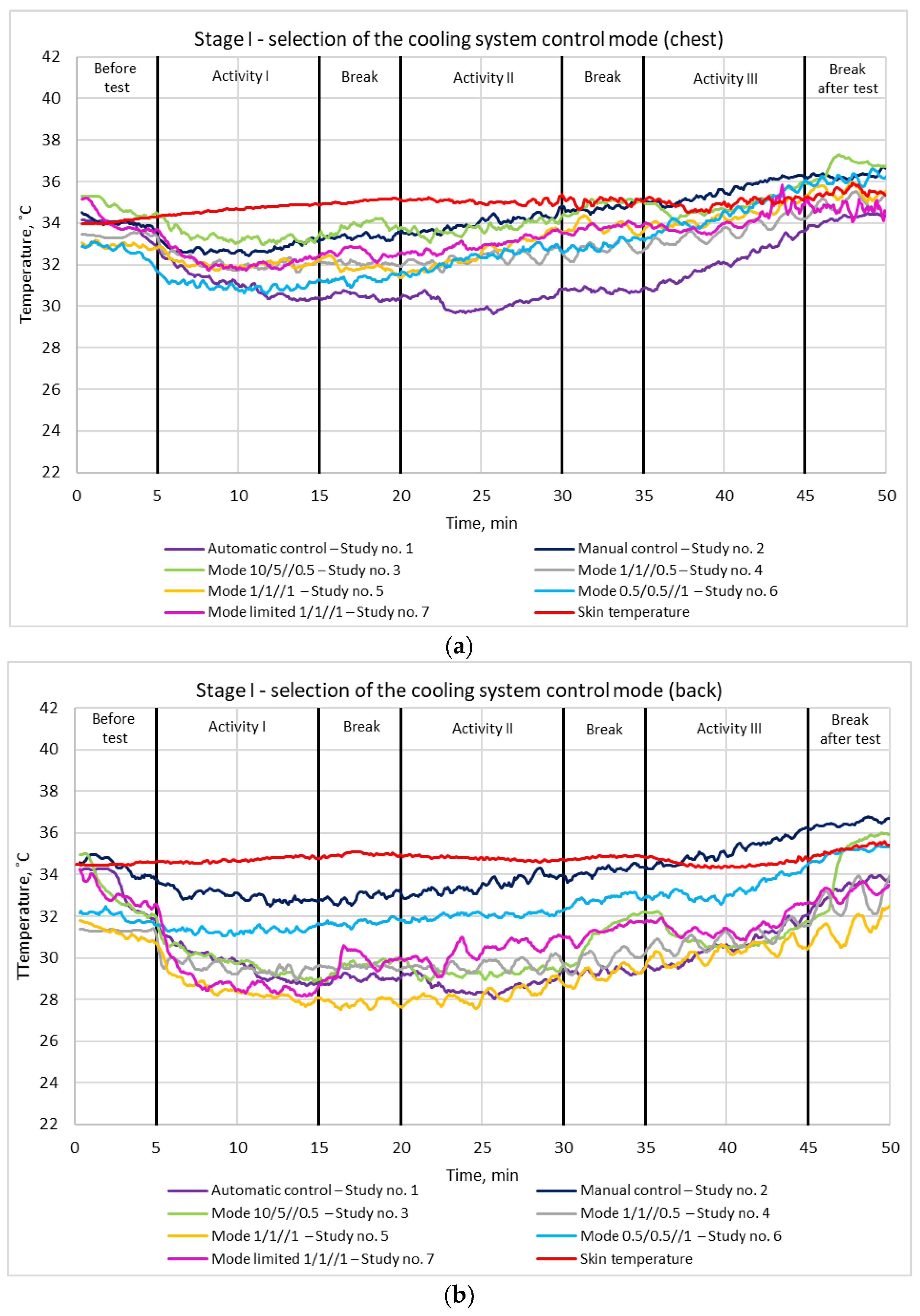
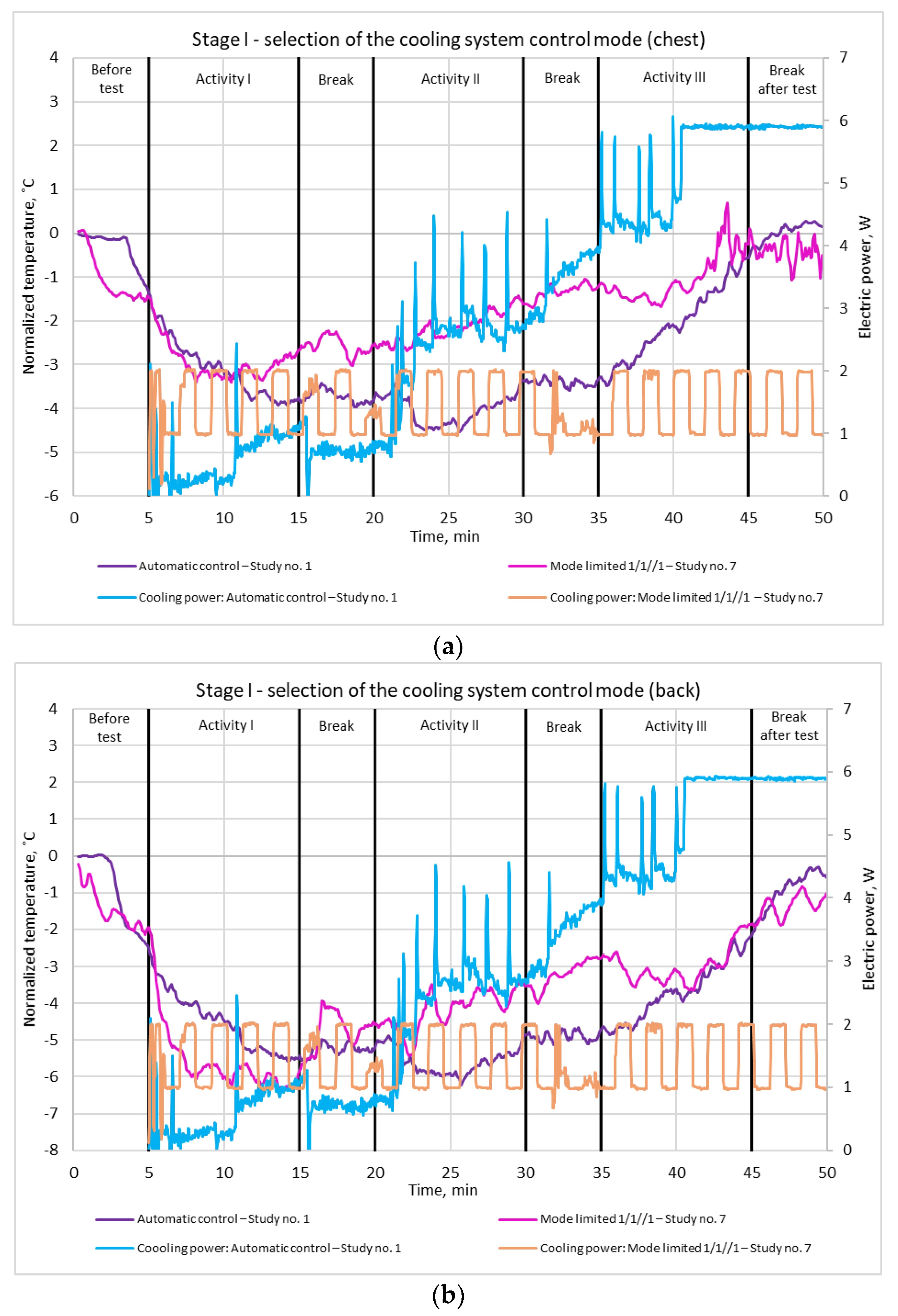
3.1. Control Mode
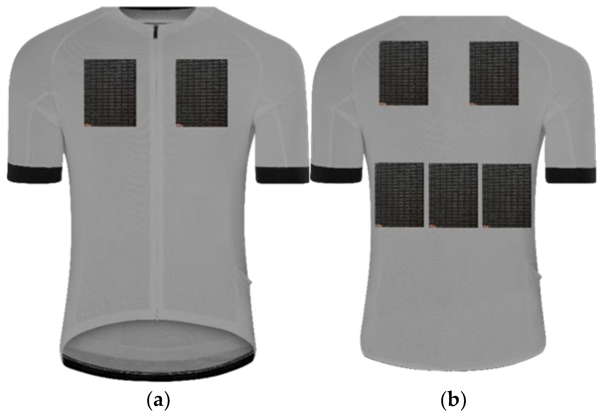
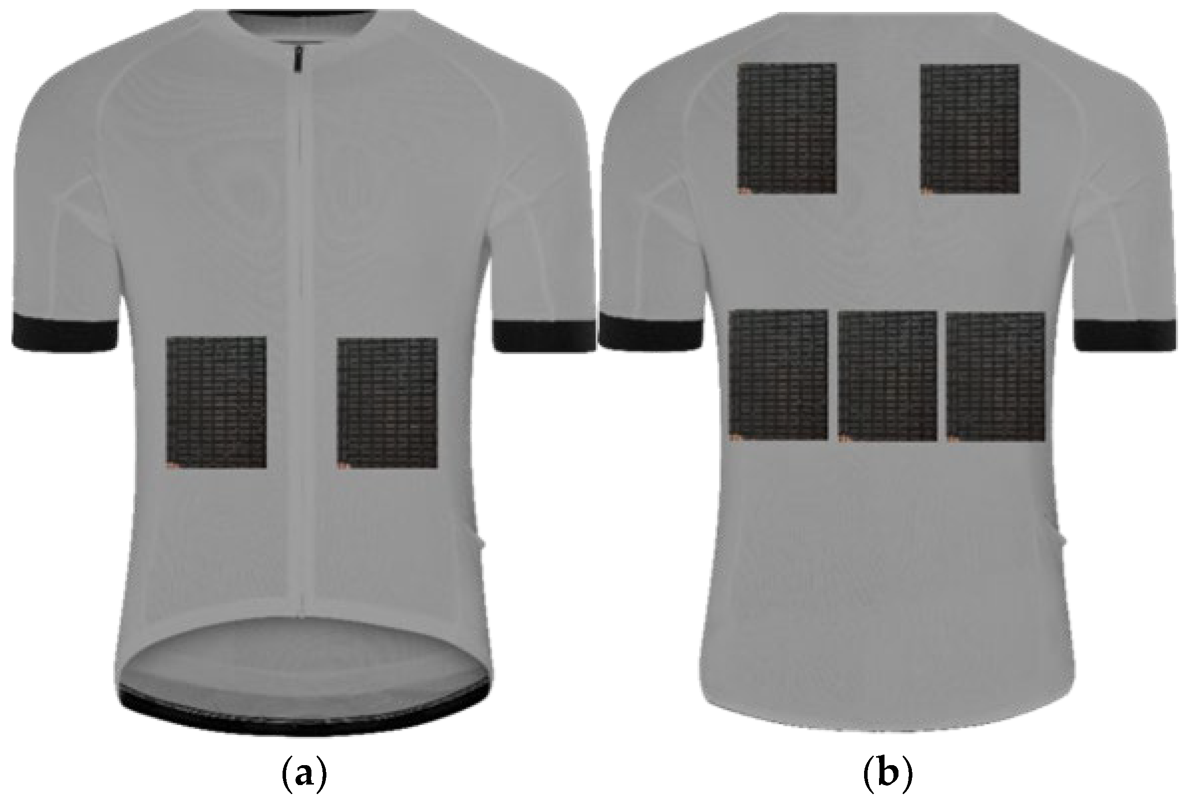
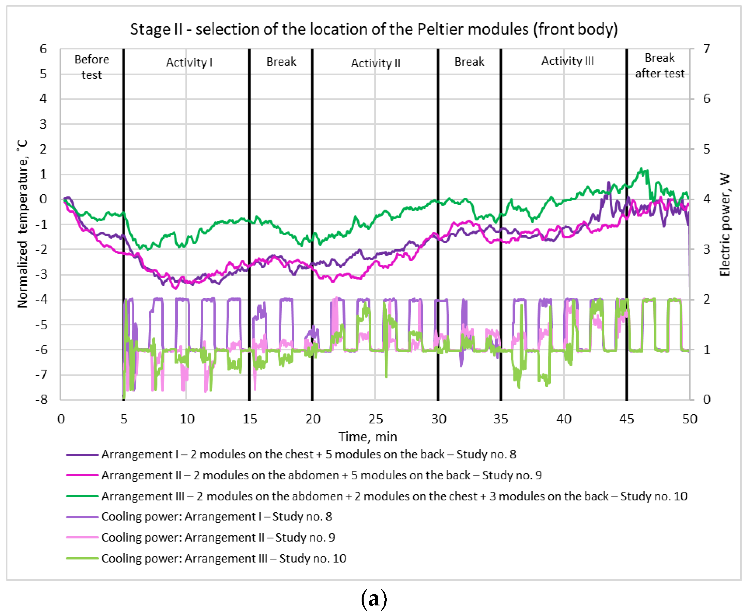
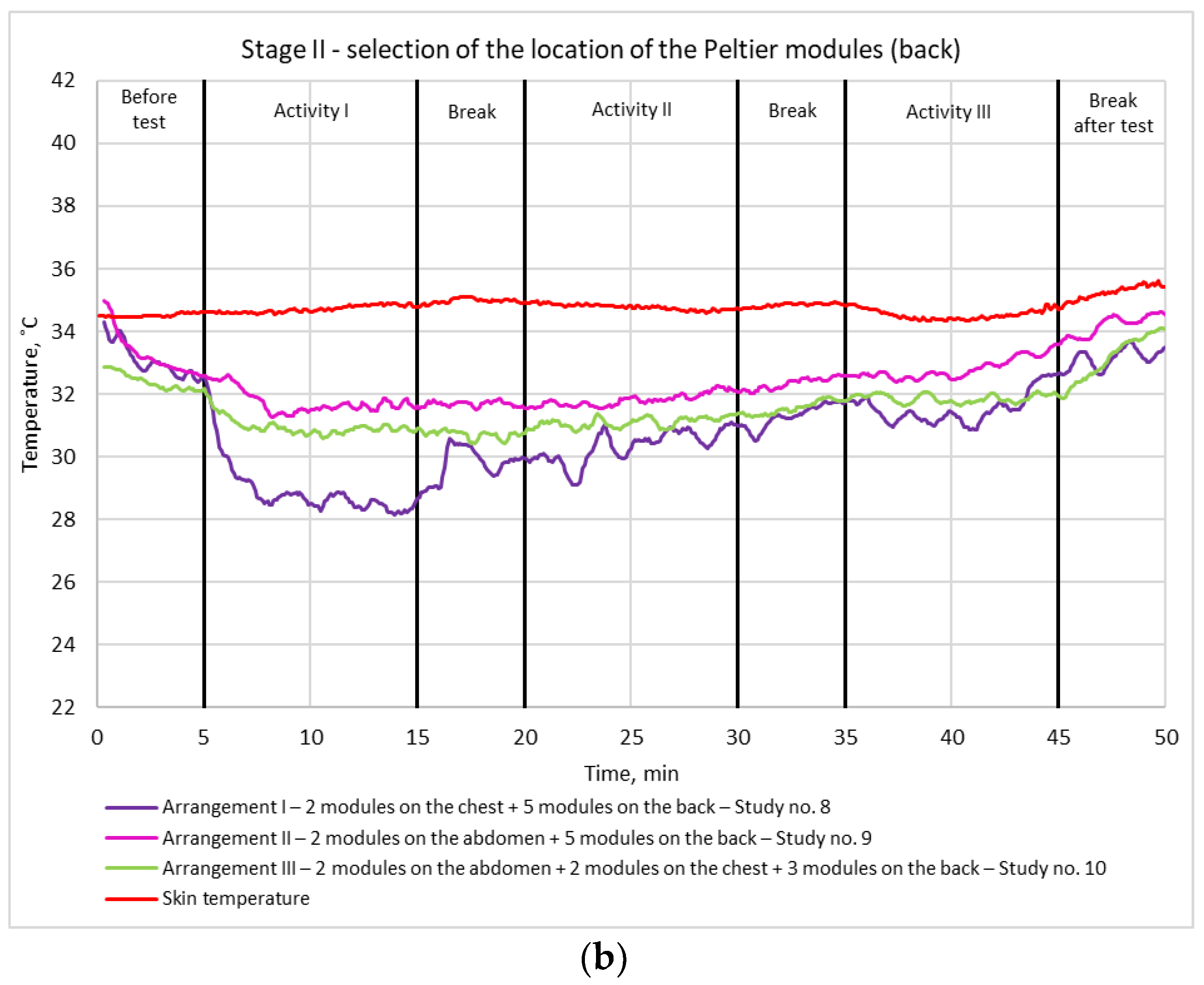
3.2. Peltier Module Arrangement
4. Discussion
5. Conclusions
Author Contributions
Funding
Institutional Review Board Statement
Informed Consent Statement
Data Availability Statement
Conflicts of Interest
References
- Tian, Z.; Lee, S.; Chen, G. A Comprehensive Review of Heat Transfer in Thermoelectric Materials and Devices. Annu. Rev. Heat Transf. 2014, 17, 425–483. [Google Scholar] [CrossRef]
- Teffah, K.; Zhang, Y.; Mou, X. Modeling and Experimentation of New Thermoelectric Cooler-Thermoelectric Generator Module. Energies 2018, 11, 576. [Google Scholar] [CrossRef] [Green Version]
- Lavanya, G.; Venkanteshwarlu, S.; Nagaraju, A.; Prasanthi, G. Cooling and Heating of Refrigerator Jacket by Using Peltier Effect. Insights Mech. Eng. 2016, 1, 26–31. [Google Scholar]
- Poikayil, J.R.; Francis, J.; Saju, D.; Suresh, A.; Varghese, J. Peltier Integrated Heating & Cooling Jacket. In Proceedings of the International Conference on Electronics, Communication and Aerospace Technology ICECA, Coimbatore, India, 20–22 April 2017. [Google Scholar]
- Hong, S.; Gu, Y.; Seo, J.K.; Wang, J.; Liu, P.; Meng, Y.S.; Xu, S.; Chen, R. Wearable thermoelectrics for personalized thermoregulation. Sci. Adv. 2019, 5, eaaw0536. [Google Scholar] [CrossRef] [PubMed] [Green Version]
- Bansvicius, R.; Rackiene, R.; Virbalis, J.A. The body cooling system integrated into the clothes. Electron. Electr. Eng. 2007, 5, 3–6. [Google Scholar]
- Sahta, I.; Baltina, I.; Blums, J.; Jurkans, V. The control of human thermal comfort by the smart clothing. In Proceedings of the 4th International Interdisciplinary Scientific Conference Society, Health, Welfare, Riga, Latvia, 22–23 November 2012; Volume 10. [Google Scholar]
- Maniktala, S. Switching Power Supplies A–Z, 2nd ed.; Newnes: Oxford, UK, 2012. [Google Scholar] [CrossRef]
- Štofanik, V.; Štofanik, A.; Cocherová, E. Design and verification of thermostat with Peltier thermoelectric modules. In Proceedings of the 21st International Conference Radioelektronika, Brno, Czech Republic, 19–20 April 2011; pp. 1–4. [Google Scholar] [CrossRef]
- Kungwalrut, P.; Numsomran, A.; Chaiyasith, P.; Chaoraingern, J.; Tipsuwanporn, V. A PIλDμ controller design for Peltier-thermoelectric cooling system. In Proceedings of the 17th International Conference on Control, Automation and Systems (ICCAS), Jeju, Korea, 18–21 October 2017; pp. 766–770. [Google Scholar] [CrossRef]
- Sombra, A.K.R.; Sampaio, F.C.; Bascopé, R.P.T.; Torrico, B.C. Digital temperature control project using Peltier modules to improve the maintenance of battery lifetime. In Proceedings of the 12th IEEE International Conference on Industry Applications (INDUSCON), Curitiba, Brazil, 20–23 November 2016; pp. 1–7. [Google Scholar] [CrossRef]
- Dąbrowska, A.; Kobus, M.; Pękosławski, B.; Starzak, Ł. A Comparative Analysis of Thermoelectric Modules for the Purpose of Ensuring Thermal Comfort in Protective Clothing. Appl. Sci. 2021, 11, 8068. [Google Scholar] [CrossRef]
- Mitsik, M.F.; Byrdina, M.V. Thermoregulation of Smart Clothing based on Peltier Elements. In Proceedings of the 2020 IEEE East-West Design & Test Symposium (EWDTS), Varna, Bulgaria, 4–7 September 2020; pp. 1–5. [Google Scholar] [CrossRef]
- Choi, J.; Dun, C.; Forsythe, C.; Gordon, M.P.; Urban, J.J. Lightweight wearable thermoelectric cooler with rationally designed flexible heatsink consisting of phase-change material/graphite/silicone elastomer. J. Mater. Chem. A 2021, 9, 15696–15703. [Google Scholar] [CrossRef]


| Stage Designation and Aim | Study No. | Arrangement of Peltier Module Locations | Control Mode 1 | Ambient Temperature (°C) |
|---|---|---|---|---|
| Stage I— Selecting the control mode | 1 | 2 modules on the chest +5 modules on the back | Automatic | 30 |
| 2 | 2 modules on the chest +5 modules on the back | Manual | 30 | |
| 3 | 2 modules on the chest +5 modules on the back | Mode 10/5//0.5— 10 min/5 min (auto/0.5 W) | 30 | |
| 4 | 2 modules on the chest +5 modules on the back | Mode 1/1//0.5— 1 min/1 min (auto/0.5 W) | 30 | |
| 5 | 2 modules on the chest +5 modules on the back | Mode 1/1//1— 1 min/1 min (auto/1 W) | 30 | |
| 6 | 2 modules on the chest +5 modules on the back | Mode 0.5/0.5//1— 0.5 min/0.5 min (auto/1 W) | 30 | |
| 7 | 2 modules on the chest +5 modules on the back | Mode limited 1/1//1— 1 min/1 min (auto/1 W), max power 2 W | 30 | |
| Stage II— Peltier module Arrangement selection | 8 | Arrangement I— 2 modules on the chest +5 modules on the back | Selected control mode as selected after Stage I | 30 |
| 9 | Arrangement II— 2 modules on the abdomen +5 modules on the back | Selected control mode as selected after Stage I | 30 | |
| 10 | Arrangement III— 2 modules on the abdomen +2 modules on the chest +3 modules on the back | Selected control mode as selected after Stage I | 30 |
Publisher’s Note: MDPI stays neutral with regard to jurisdictional claims in published maps and institutional affiliations. |
© 2022 by the authors. Licensee MDPI, Basel, Switzerland. This article is an open access article distributed under the terms and conditions of the Creative Commons Attribution (CC BY) license (https://creativecommons.org/licenses/by/4.0/).
Share and Cite
Dąbrowska, A.; Kobus, M.; Starzak, Ł.; Pękosławski, B. Analysis of Efficiency of Thermoelectric Personal Cooling System Based on Utility Tests. Materials 2022, 15, 1115. https://doi.org/10.3390/ma15031115
Dąbrowska A, Kobus M, Starzak Ł, Pękosławski B. Analysis of Efficiency of Thermoelectric Personal Cooling System Based on Utility Tests. Materials. 2022; 15(3):1115. https://doi.org/10.3390/ma15031115
Chicago/Turabian StyleDąbrowska, Anna, Monika Kobus, Łukasz Starzak, and Bartosz Pękosławski. 2022. "Analysis of Efficiency of Thermoelectric Personal Cooling System Based on Utility Tests" Materials 15, no. 3: 1115. https://doi.org/10.3390/ma15031115