
New Concept for the Facile Fabrication of Core–Shell CuO@CuFe2O4 Photocathodes for PEC Application

 , , , , , and
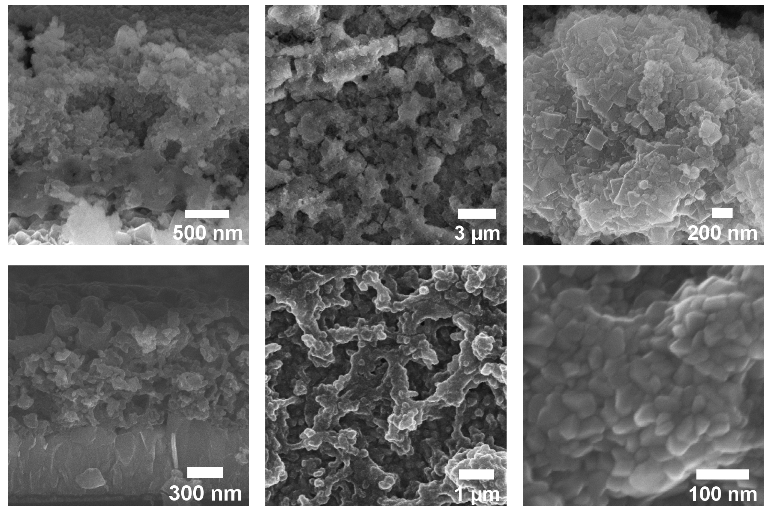
Abstract
:1. Introduction
2. Materials and Methods
2.1. Preparation of CuO@CuFe2O4
2.2. Characterization Methods
2.3. PEC Measurement
3. Results and Discussion
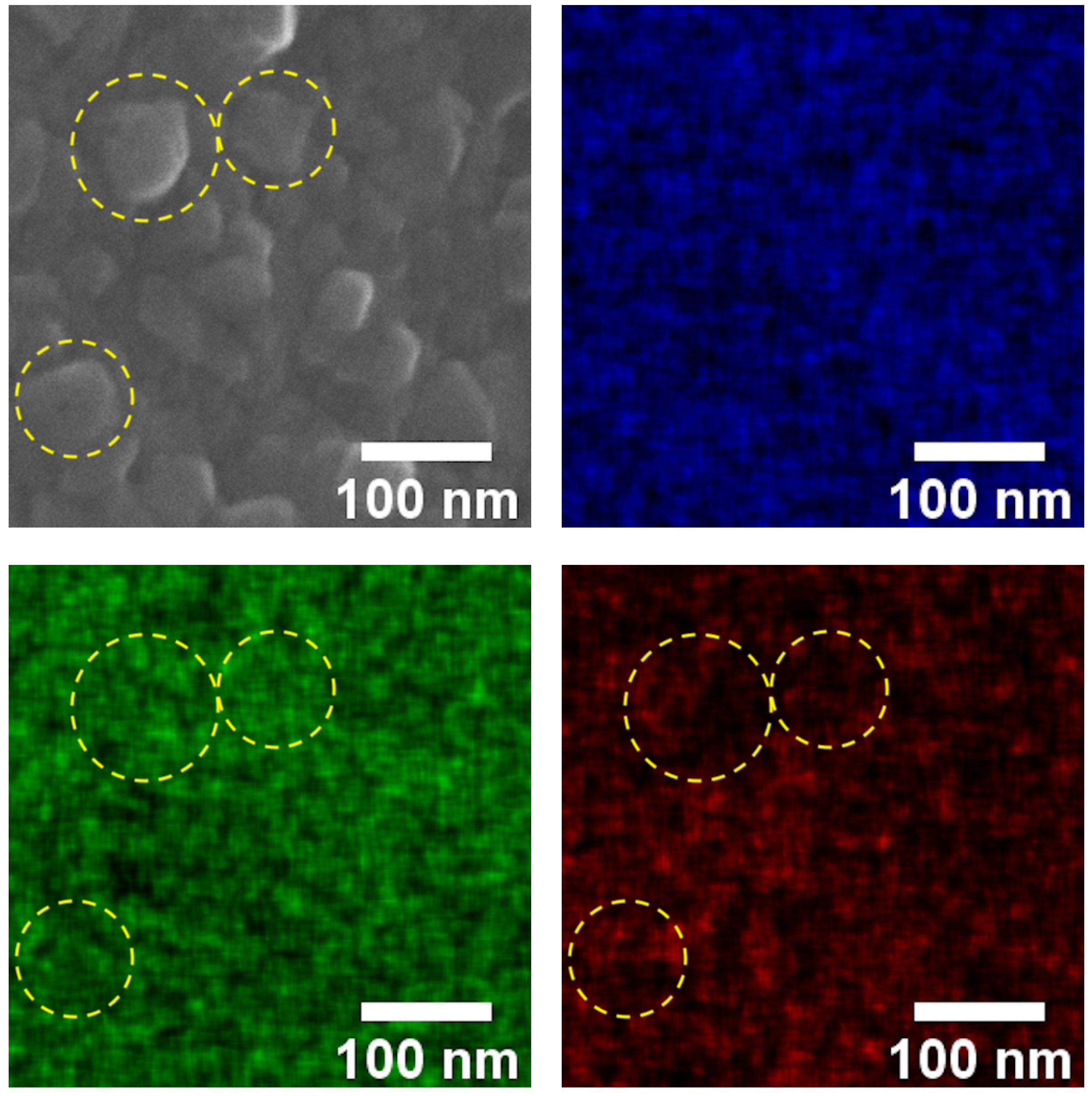
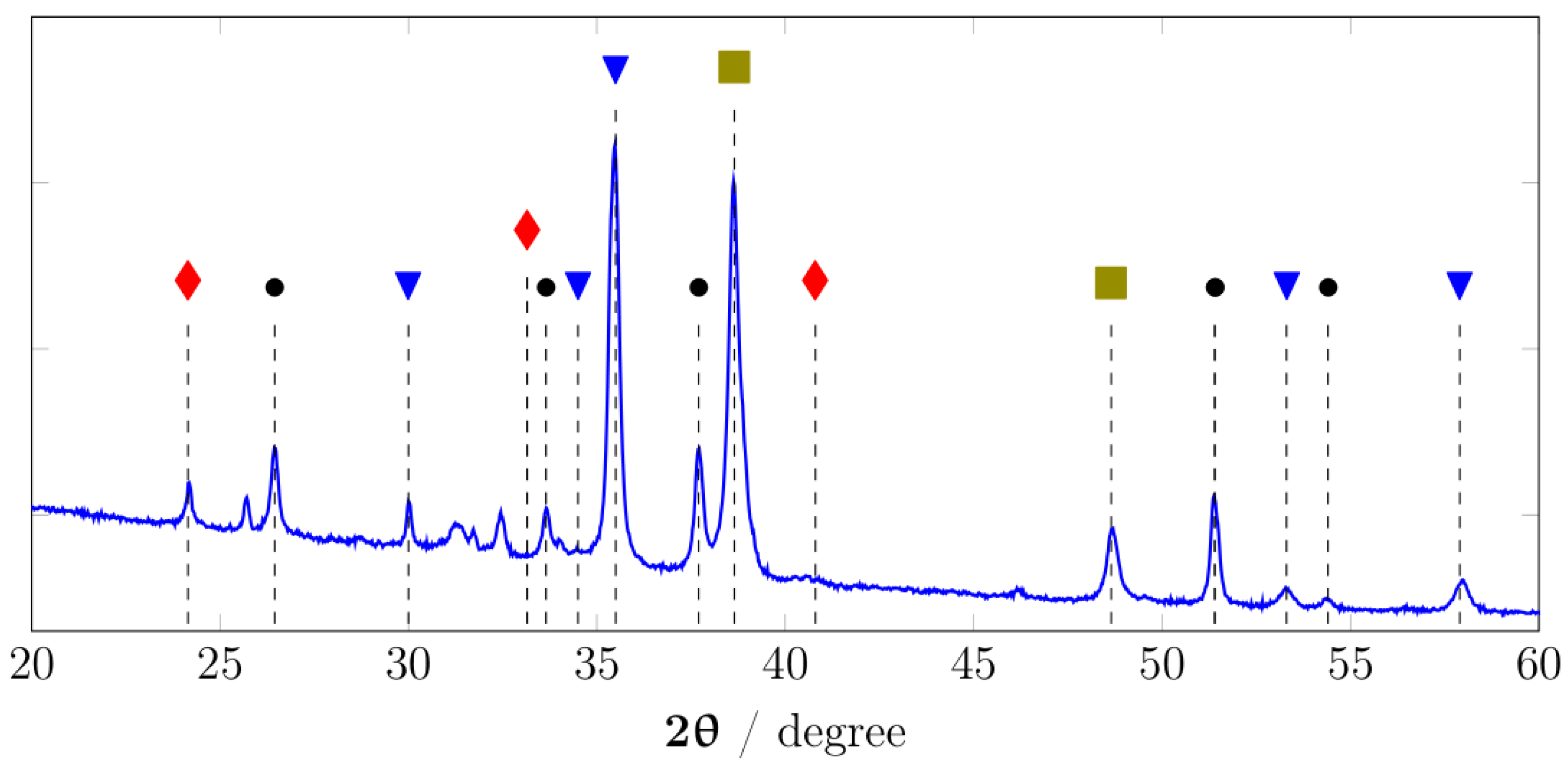
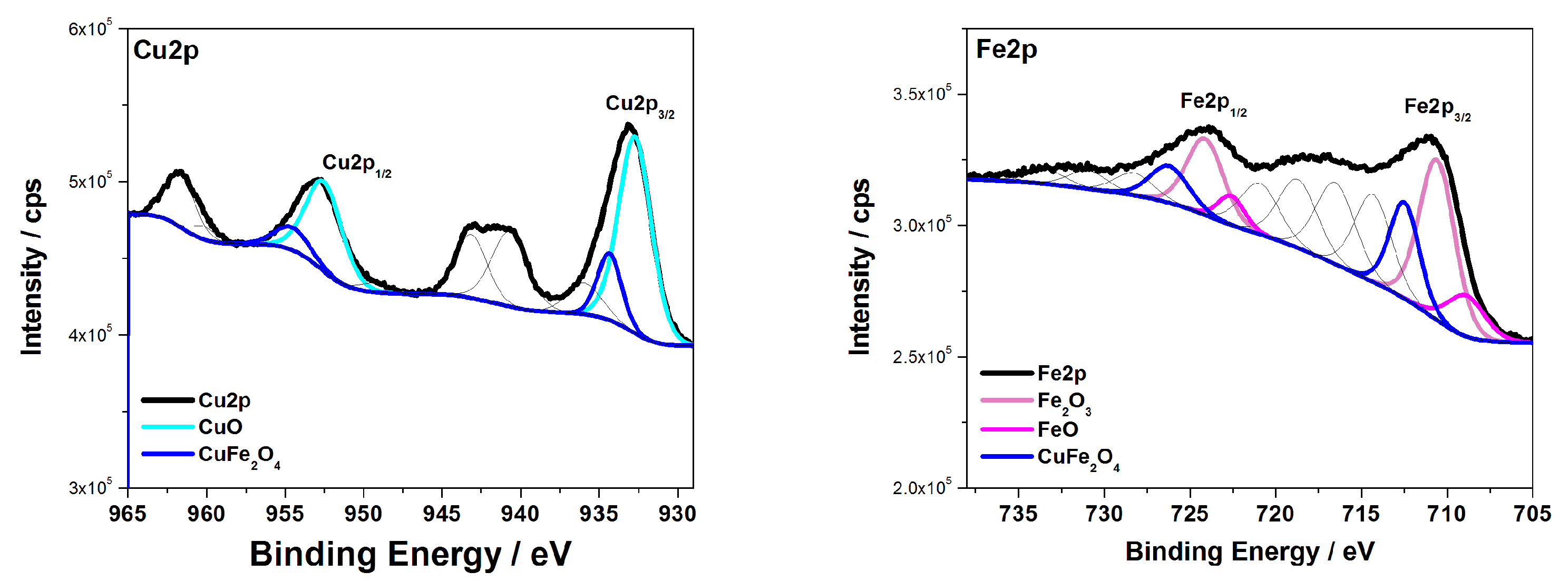
3.1. Characterization
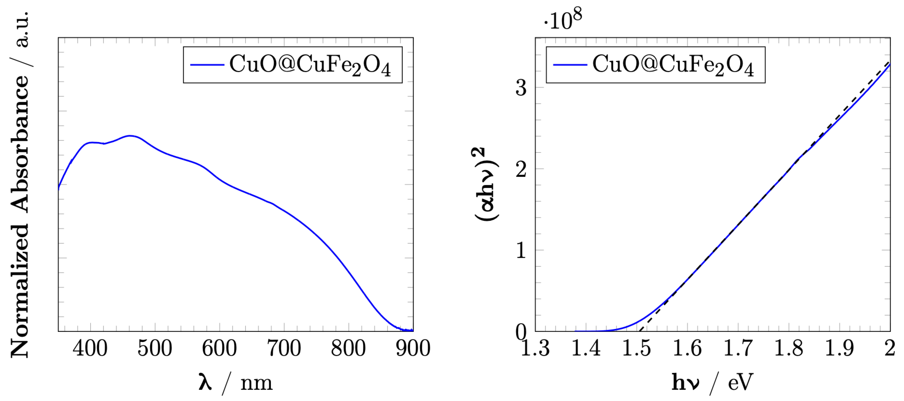
3.2. Optical Properties
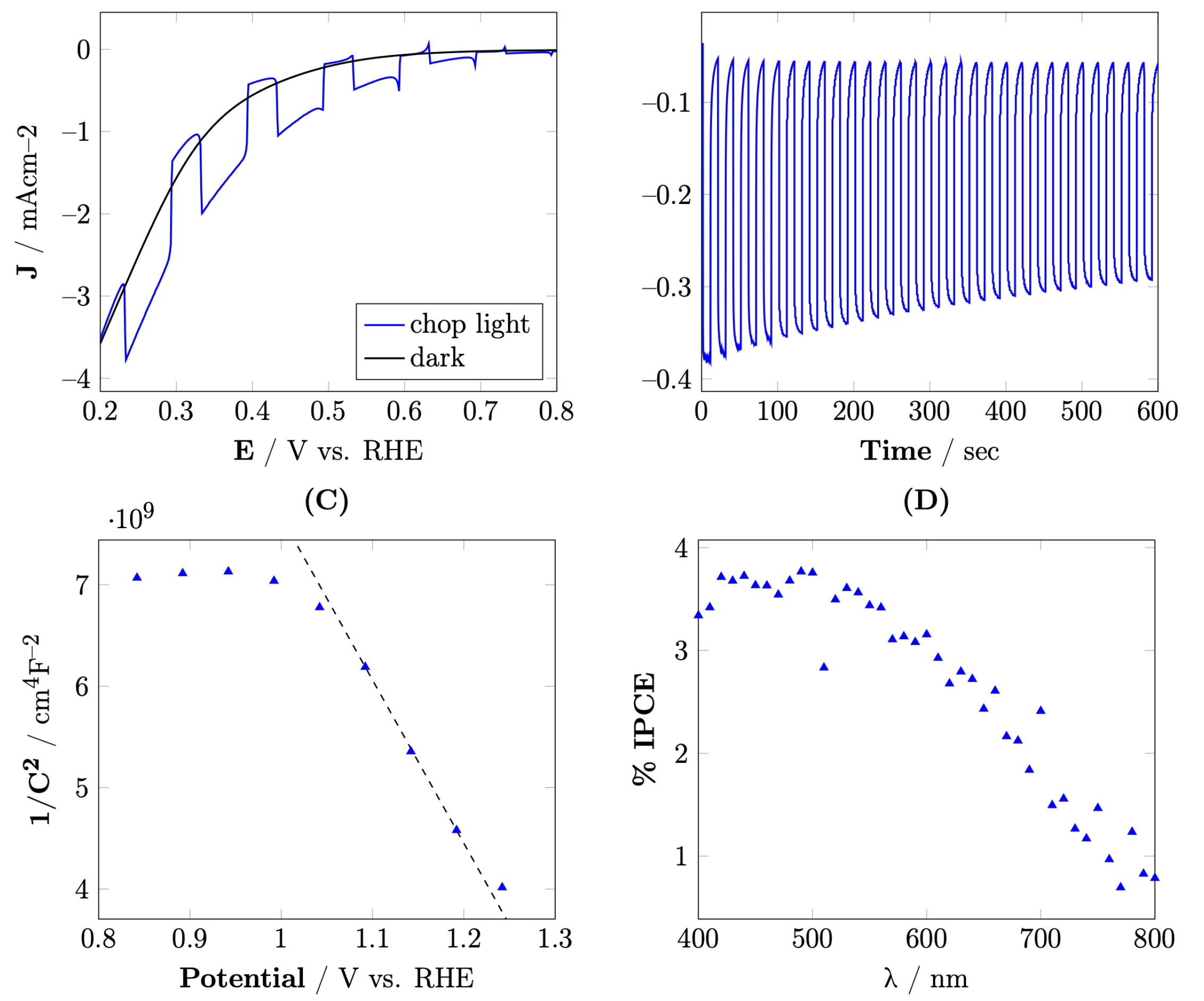
3.3. Photoelectrochemical Properties
4. Conclusions
Supplementary Materials
Author Contributions
Funding
Institutional Review Board Statement
Informed Consent Statement
Data Availability Statement
Acknowledgments
Conflicts of Interest
Sample Availability
References
- Walter, M.G.; Warren, E.L.; McKone, J.R.; Boettcher, S.W.; Mi, Q.; Santori, E.A.; Lewis, N.S. Solar water splitting cells. Chem. Rev. 2010, 110, 6446–6473. [Google Scholar] [CrossRef]
- Sivula, K. Solar-to-chemical energy conversion with photoelectrochemical tandem cells. Chimia 2013, 67, 155–161. [Google Scholar] [CrossRef]
- Li, J.; Wu, N. Semiconductor-based photocatalysts and photoelectrochemical cells for solar fuel generation: A review. Catal. Sci. Technol. 2015, 5, 1360–1384. [Google Scholar] [CrossRef]
- Jang, Y.J.; Lee, J.S. Photoelectrochemical Water Splitting with p-Type Metal Oxide Semiconductor Photocathodes. ChemSusChem 2019, 12, 1835–1845. [Google Scholar] [CrossRef]
- Kezzim, A.; Nasrallah, N.; Abdi, A.; Trari, M. Visible light induced hydrogen on the novel hetero-system CuFe2O4/TiO2. Energy Convers. Manag. 2011, 52, 2800–2806. [Google Scholar] [CrossRef]
- Liu, Y.; He, H.; Li, J.; Li, W.; Yang, Y.; Li, Y.; Chen, Q. Preparation and enhanced photoelectrochemical performance of a p-n heterojunction CuFe2O4/WO3 nanocomposite film. RSC Adv. 2015, 5, 99378–99384. [Google Scholar] [CrossRef]
- Hussain, S.; Hussain, S.; Waleed, A.; Tavakoli, M.M.; Wang, Z.; Yang, S.; Fan, Z.; Nadeem, M.A. Fabrication of CuFe2O4/α-Fe2O3 Composite Thin Films on FTO Coated Glass and 3-D Nanospike Structures for Efficient Photoelectrochemical Water Splitting. ACS Appl. Mater. Interfaces 2016, 8, 35315–35322. [Google Scholar] [CrossRef]
- Tarek, M.; Rezaul Karim, K.M.; Sarkar, S.M.; Deb, A.; Ong, H.R.; Abdullah, H.; Cheng, C.K.; Rahman Khan, M.M. Hetero-structure CdS–CuFe2O4 as an efficient visible light active photocatalyst for photoelectrochemical reduction of CO2 to methanol. Int. J. Hydrogen Energy 2019, 44, 26271–26284. [Google Scholar] [CrossRef]
- Liu, Y.; Le Formal, F.; Boudoire, F.; Yao, L.; Sivula, K.; Guijarro, N. Insights into the interfacial carrier behaviour of copper ferrite (CuFe2O4) photoanodes for solar water oxidation. J. Mater. Chem. A 2019, 7, 1669–1677. [Google Scholar] [CrossRef]
- Saadi, S.; Bouguelia, A.; Trari, M. Photoassisted hydrogen evolution over spinel CuM2O4 (M=Al, Cr, Mn, Fe and Co). Renew. Energy 2006, 31, 2245–2256. [Google Scholar] [CrossRef]
- Helaïli, N.; Bessekhouad, Y.; Bachari, K.; Trari, M. Synthesis and physical properties of the CuFe2-xMnxO4 (0 ≤ x ≤ 2) solid solution. Mater. Chem. Phys. 2014, 148, 734–743. [Google Scholar] [CrossRef]
- Díez-García, M.I.; Lana-Villarreal, T.; Gómez, R. Study of Copper Ferrite as a Novel Photocathode for Water Reduction: Improving Its Photoactivity by Electrochemical Pretreatment. ChemSusChem 2016, 9, 1504–1512. [Google Scholar] [CrossRef]
- Li, X.; Liu, A.; Chu, D.; Zhang, C.; Du, Y.; Huang, J.; Yang, P. High performance of manganese porphyrin sensitized p-type CuFe2O4 photocathode for solar water splitting to produce hydrogen in a tandem photoelectrochemical cell. Catalysts 2018, 8, 108. [Google Scholar] [CrossRef] [Green Version]
- Zhang, E.; Wang, L.; Zhang, B.; Xie, Y.; Wang, G. Shape-controlled hydrothermal synthesis of CuFe2O4 nanocrystals for enhancing photocatalytic and photoelectrochemical performance. Mater. Chem. Phys. 2019, 235, 121633. [Google Scholar] [CrossRef]
- Tsege, E.L.; Atabaev, T.S.; Hossain, M.A.; Lee, D.; Kim, H.K.; Hwang, Y.H. Cu-doped flower-like hematite nanostructures for efficient water splitting applications. J. Phys. Chem. Solids 2016, 98, 283–289. [Google Scholar] [CrossRef]
- Kyesmen, P.I.; Nombona, N.; Diale, M. Heterojunction of nanostructured α-Fe2O3/CuO for enhancement of photoelectrochemical water splitting. J. Alloys Compd. 2021, 863, 158724. [Google Scholar] [CrossRef]
- Park, S.; Baek, J.H.; Zhang, L.; Lee, J.M.; Stone, K.H.; Cho, I.S.; Guo, J.; Jung, H.S.; Zheng, X. Rapid Flame-Annealed CuFe2O4 as Efficient Photocathode for Photoelectrochemical Hydrogen Production. ACS Sustain. Chem. Eng. 2019, 7, 5867–5874. [Google Scholar] [CrossRef]
- Maitra, S.; Pal, S.; Maitra, T.; Halder, S.; Roy, S. Solvothermal Etching-Assisted Phase and Morphology Tailoring in Highly Porous CuFe2O4 Nanoflake Photocathodes for Solar Water Splitting. Energy Fuels 2021, 35, 14087–14100. [Google Scholar] [CrossRef]
- Catala, L.; Mallah, T. Nanoparticles of Prussian blue analogs and related coordination polymers: From information storage to biomedical applications. Coord. Chem. Rev. 2017, 346, 32–61. [Google Scholar] [CrossRef]
- Zakaria, M.B.; Hu, M.; Imura, M.; Salunkhe, R.R.; Umezawa, N.; Hamoudi, H.; Belik, A.A.; Yamauchi, Y. Single-crystal-like nanoporous spinel oxides: A strategy for synthesis of nanoporous metal oxides utilizing metal-cyanide hybrid coordination polymers. Chem. A Eur. J. 2014, 20, 17375–17384. [Google Scholar] [CrossRef]
- Xiao, L.; Youji, L.; Feitai, C.; Peng, X.; Ming, L. Facile synthesis of mesoporous titanium dioxide doped by Ag-coated graphene with enhanced visible-light photocatalytic performance for methylene blue degradation. RSC Adv. 2017, 7, 25314–25324. [Google Scholar] [CrossRef] [Green Version]
- Lin, X.; Du, S.; Li, C.; Li, G.; Li, Y.; Chen, F.; Fang, P. Consciously Constructing the Robust NiS/g-C3N4 Hybrids for Enhanced Photocatalytic Hydrogen Evolution. Catal. Letters 2020, 150, 1898–1908. [Google Scholar] [CrossRef]
- Momma, K.; Izumi, F. VESTA 3 for three-dimensional visualization of crystal, volumetric and morphology data. J. Appl. Crystallogr. 2011, 44, 1272–1276. [Google Scholar] [CrossRef]
- Yadav, R.S.; Havlica, J.; Masilko, J.; Kalina, L.; Wasserbauer, J.; Hajdúchová, M.; Enev, V.; Kuřitka, I.; Kožáková, Z. Cation Migration-Induced Crystal Phase Transformation in Copper Ferrite Nanoparticles and Their Magnetic Property. J. Supercond. Nov. Magn. 2016, 29, 759–769. [Google Scholar] [CrossRef]
- Chatterjee, B.K.; Bhattacharjee, K.; Dey, A.; Ghosh, C.K.; Chattopadhyay, K.K. Influence of spherical assembly of copper ferrite nanoparticles on magnetic properties: Orientation of magnetic easy axis. Dalt. Trans. 2014, 43, 7930–7944. [Google Scholar] [CrossRef]
- Biesinger, M.C.; Payne, B.P.; Grosvenor, A.P.; Lau, L.W.; Gerson, A.R.; Smart, R.S.C. Resolving surface chemical states in XPS analysis of first row transition metals, oxides and hydroxides: Cr, Mn, Fe, Co and Ni. Appl. Surf. Sci. 2011, 257, 2717–2730. [Google Scholar] [CrossRef]
- Biesinger, M.C. Advanced analysis of copper X-ray photoelectron spectra. Surf. Interface Anal. 2017, 49, 1325–1334. [Google Scholar] [CrossRef]
- Liu, Y.; Zhang, H.; Fu, W.; Yang, Z.; Li, Z. Characterization of temperature sensitivity of V-modified CuFe2O4 ceramics for NTC thermistors. J. Mater. Sci. Mater. Electron. 2018, 29, 18797–18806. [Google Scholar] [CrossRef]
- Zhang, E.; Wang, L.; Zhang, B.; Xie, Y.; Wang, G. Enhanced photocatalytic performance of polyvinylidene fluoride membrane by doped CuFe2O4 nanocrystals for water treatment. J. Sol.-Gel. Sci. Technol. 2020, 93, 452–461. [Google Scholar] [CrossRef]
- Naumkin, A.; Kraut-Vass, A.; Gaarenstroom, S.W.; Powell, C. NIST X-ray Photoelectron Spectroscopy (XPS) Database, Version 4.1. Available online: https://srdata.nist.gov/xps/ (accessed on 29 December 2021).
- Moulder, J.F.; Stickle, W.F.; Sobol, P.E.; Bomben, K.D. Handbook of X-ray Photoelectron Spectroscopy; Perkin-Elmer: Boston, MA, USA, 1992; p. 262. [Google Scholar]
- Grosvenor, A.P.; Kobe, B.A.; Biesinger, M.C.; McIntyre, N.S. Investigation of multiplet splitting of Fe2p XPS spectra and bonding in iron compounds. Surf. Interface Anal. 2004, 36, 1564–1574. [Google Scholar] [CrossRef]
- Marotti, R.E.; Giorgi, P.; Machado, G.; Dalchiele, E.A. Crystallite size dependence of band gap energy for electrodeposited ZnO grown at different temperatures. Sol. Energy Mater. Sol. Cells 2006, 90, 2356–2361. [Google Scholar] [CrossRef]
- Li, C.; He, J.; Xiao, Y.; Li, Y.; Delaunay, J.J. Earth-abundant Cu-based metal oxide photocathodes for photoelectrochemical water splitting. Energy Environ. Sci. 2020, 10, 3269–3306. [Google Scholar] [CrossRef]
- Karim, K.M.R.; Ong, H.R.; Abdullah, H.; Yousuf, A.; Cheng, C.K.; Khan, M.M.R. Electrochemical study of copper ferrite as a catalyst for CO2 photoelectrochemical reduction. Bull. Chem. React. Eng. Catal. 2018, 13, 236–244. [Google Scholar] [CrossRef] [Green Version]
- Nolan, M.; Elliott, S.D. The p-type conduction mechanism in Cu2O: A first principles study. Phys. Chem. Chem. Phys. 2006, 8, 5350–5358. [Google Scholar] [CrossRef] [PubMed]
- Attia, S.; Helaïli, N.; Bessekhouad, Y.; Trari, M. Visible Light Hydrogen Production on the Novel Ferrite CuFe2O4. In Advances in Renewable Hydrogen and Other Sustainable Energy Carriers; Springer: Singapore, 2021; pp. 105–112. [Google Scholar] [CrossRef]


Publisher’s Note: MDPI stays neutral with regard to jurisdictional claims in published maps and institutional affiliations. |
© 2022 by the authors. Licensee MDPI, Basel, Switzerland. This article is an open access article distributed under the terms and conditions of the Creative Commons Attribution (CC BY) license (https://creativecommons.org/licenses/by/4.0/).
Share and Cite
Trinh, L.; Bienkowski, K.; Wróbel, P.; Pisarek, M.; Parzuch, A.; Nawaz, N.; Solarska, R. New Concept for the Facile Fabrication of Core–Shell CuO@CuFe2O4 Photocathodes for PEC Application. Materials 2022, 15, 1029. https://doi.org/10.3390/ma15031029
Trinh L, Bienkowski K, Wróbel P, Pisarek M, Parzuch A, Nawaz N, Solarska R. New Concept for the Facile Fabrication of Core–Shell CuO@CuFe2O4 Photocathodes for PEC Application. Materials. 2022; 15(3):1029. https://doi.org/10.3390/ma15031029
Chicago/Turabian StyleTrinh, Linh, Krzysztof Bienkowski, Piotr Wróbel, Marcin Pisarek, Aleksandra Parzuch, Nabila Nawaz, and Renata Solarska. 2022. "New Concept for the Facile Fabrication of Core–Shell CuO@CuFe2O4 Photocathodes for PEC Application" Materials 15, no. 3: 1029. https://doi.org/10.3390/ma15031029