
Line Shape Analysis and Dynamic Response of Ballastless Track during Jacking Rectification Fixing

 , and
, and
Abstract
:1. Introduction
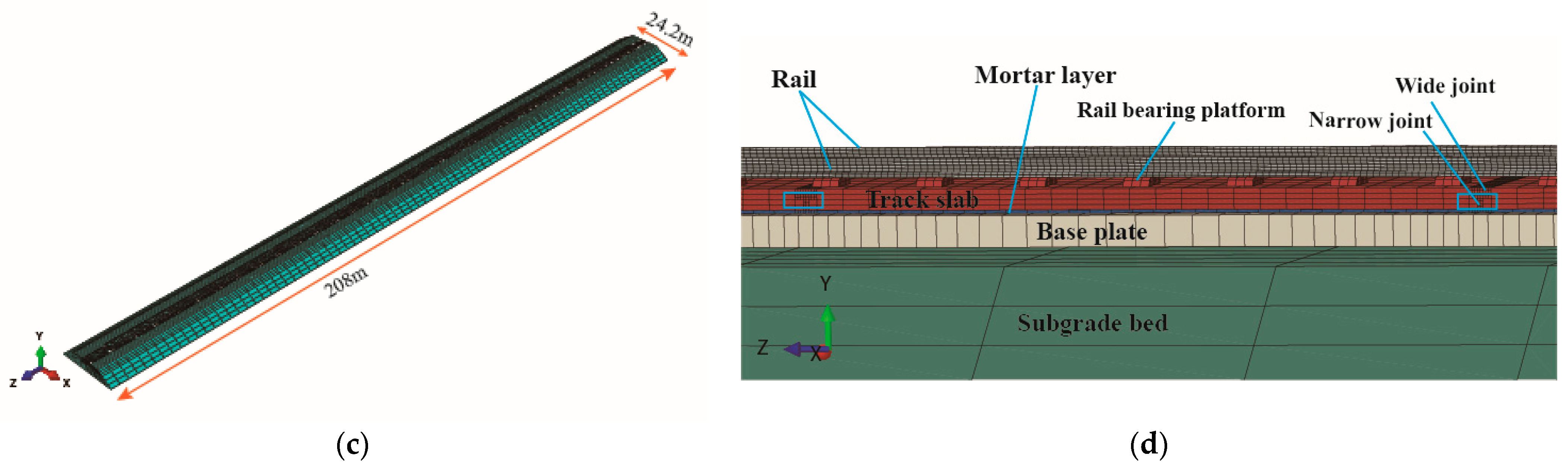
2. Numerical Model
3. Mechanical Behaviour under Jacking Pressure
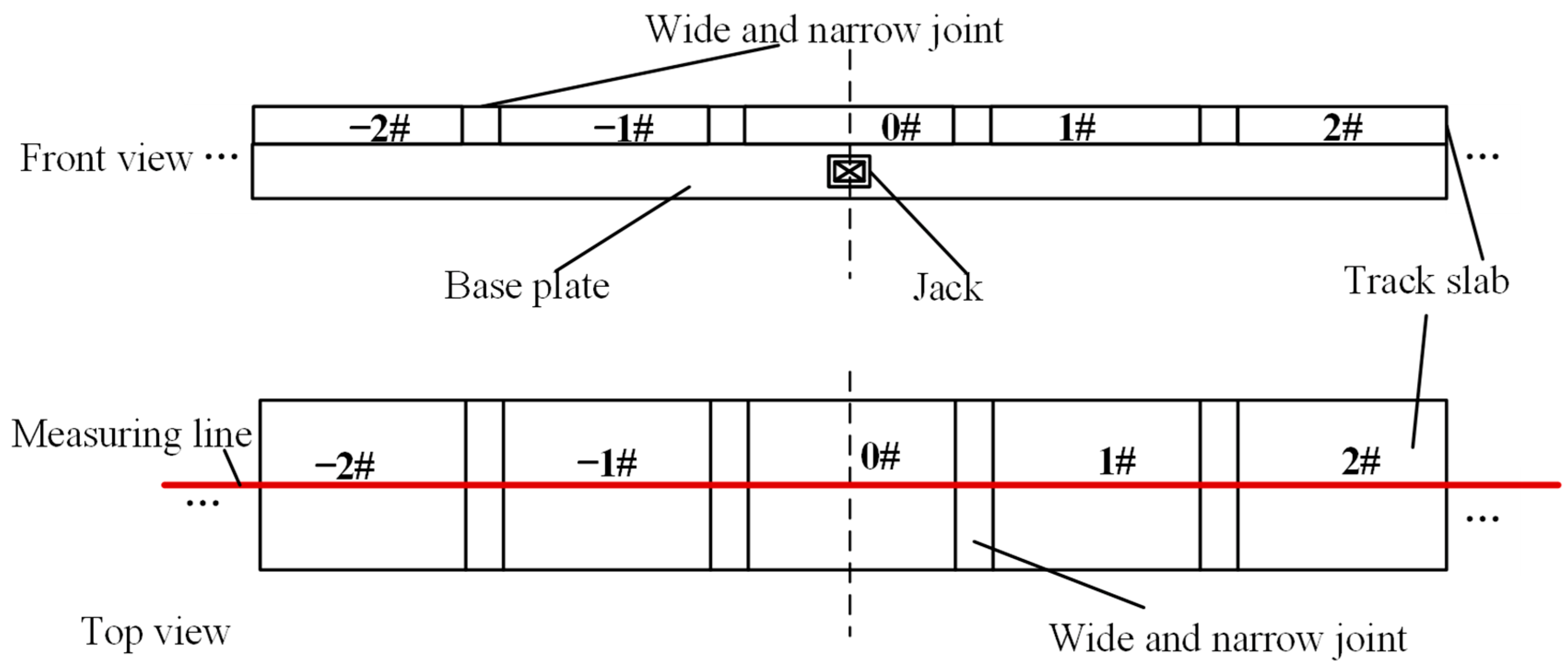
3.1. Single Point Jacking
3.2. Multi-Point Jacking
3.3. Damage Analysis for Wide-Narrow Joint during Single Point Jacking
3.4. Damage Analysis for Wide-Narrow Joint during Multi-Point Jacking
4. Dynamic Response of the Track Structure during the Jacking Rectification Interval
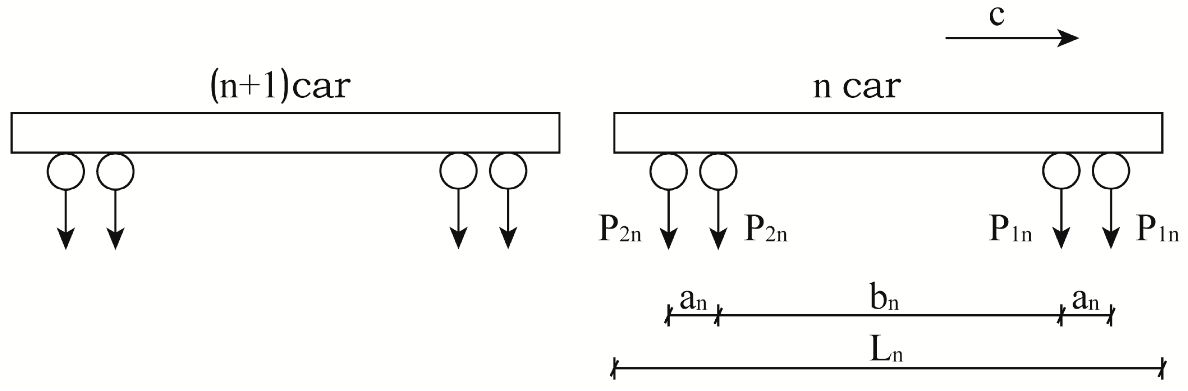
4.1. Train Loading Profile
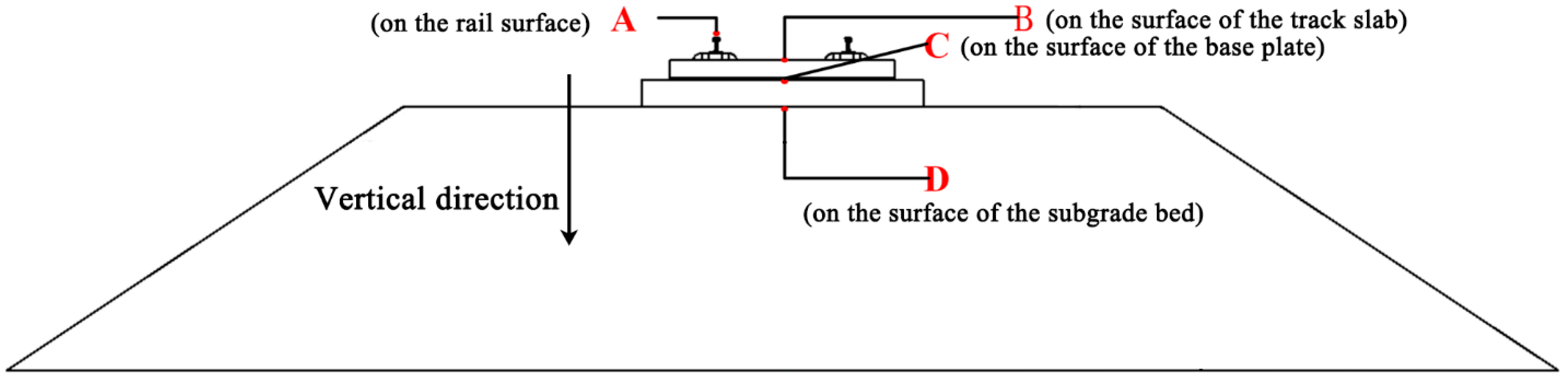
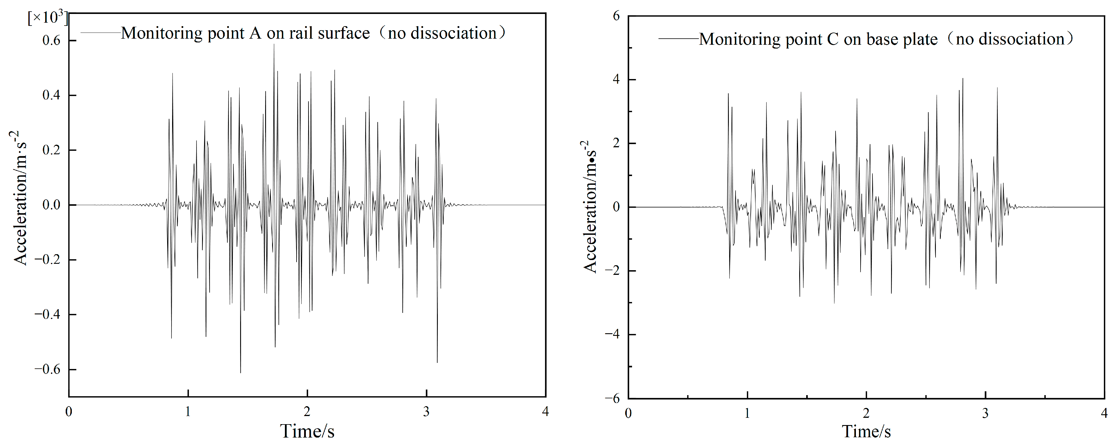
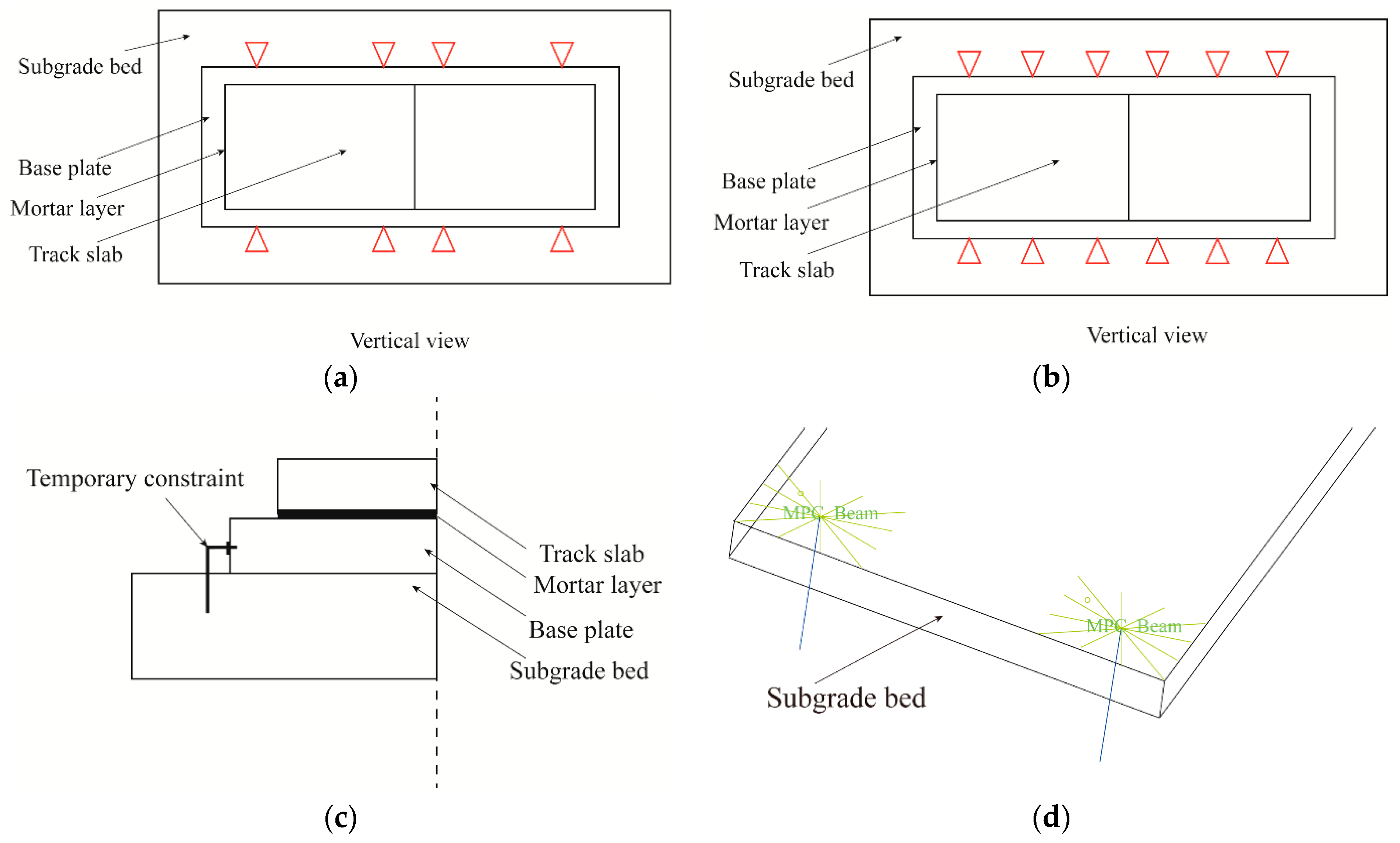
4.2. Location of Measurement Points
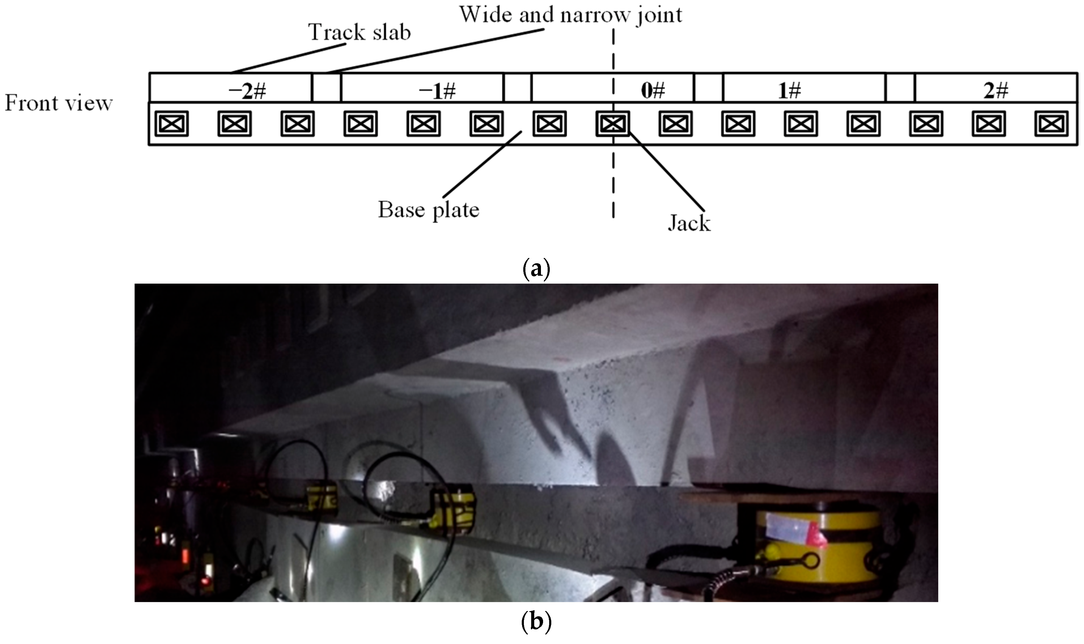
4.3. Model Validation
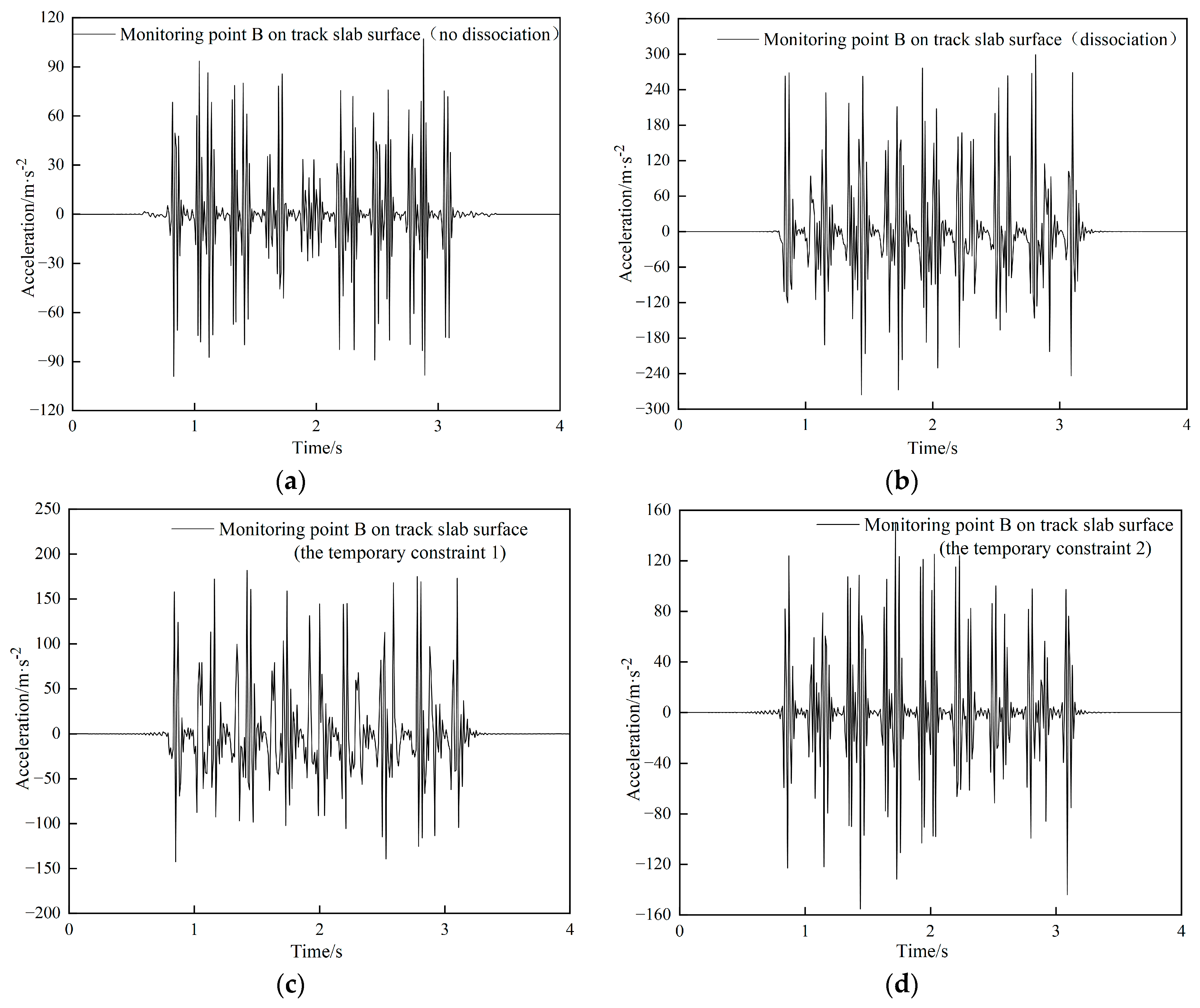
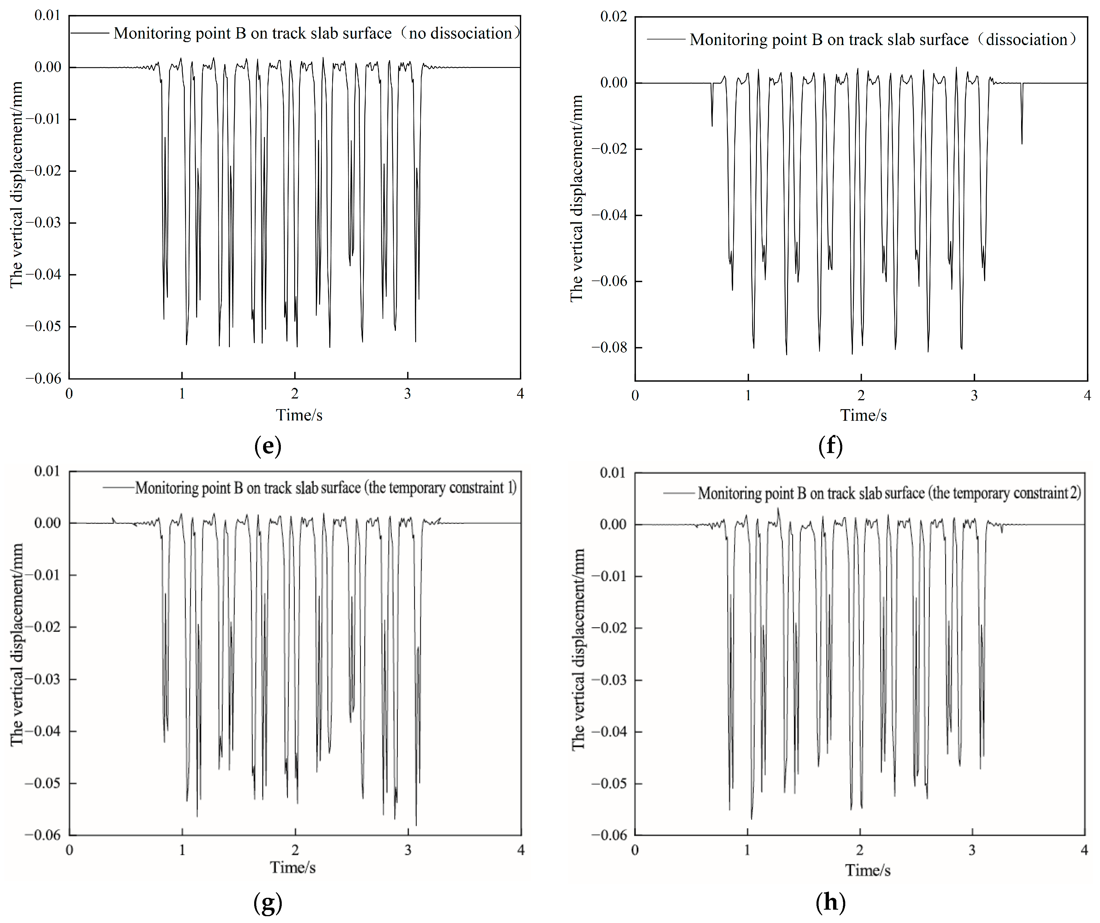
4.4. Dynamic Response of Track Structures under Different Operating Conditions
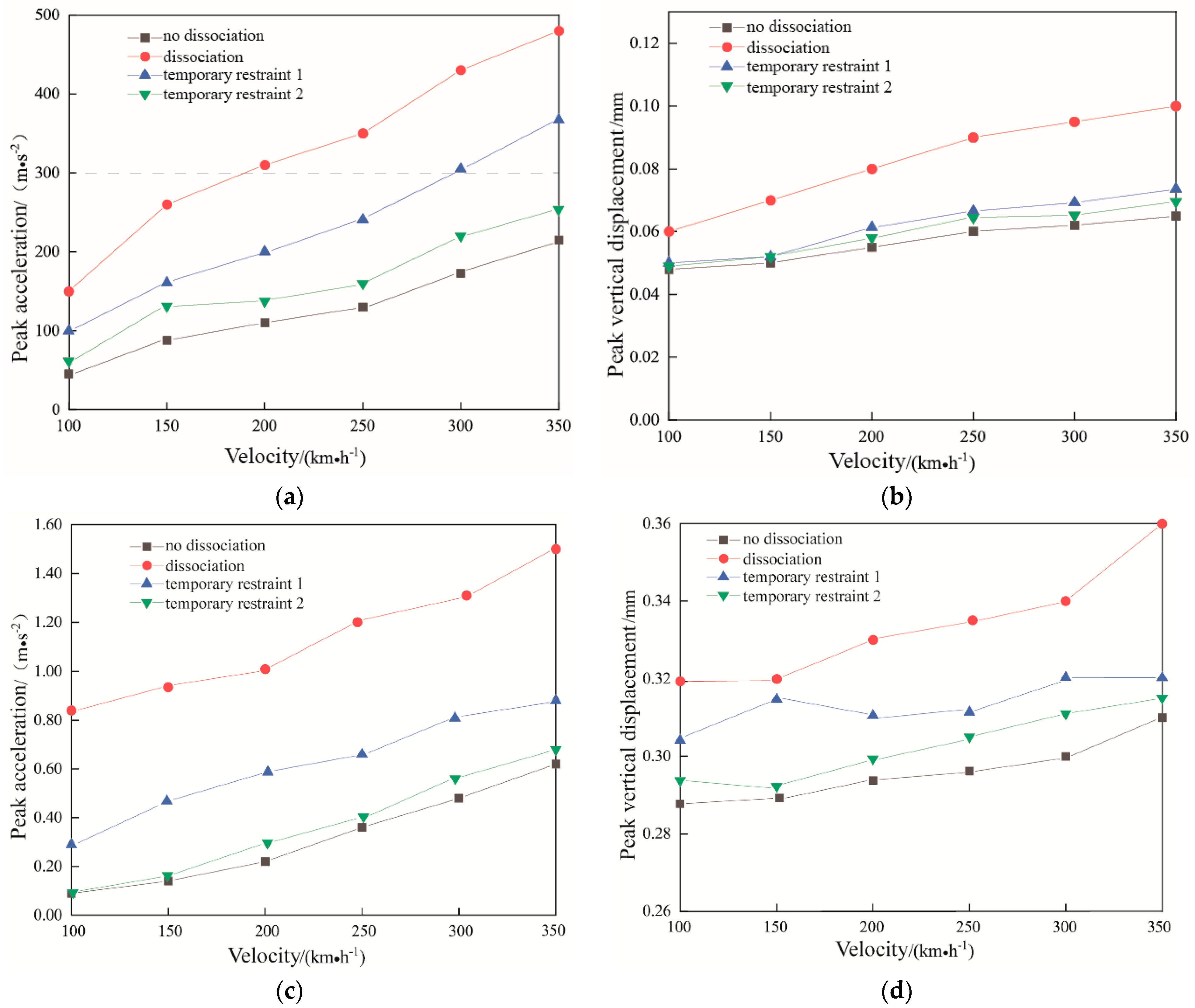
4.5. Influence of Travel Speed
5. Conclusions
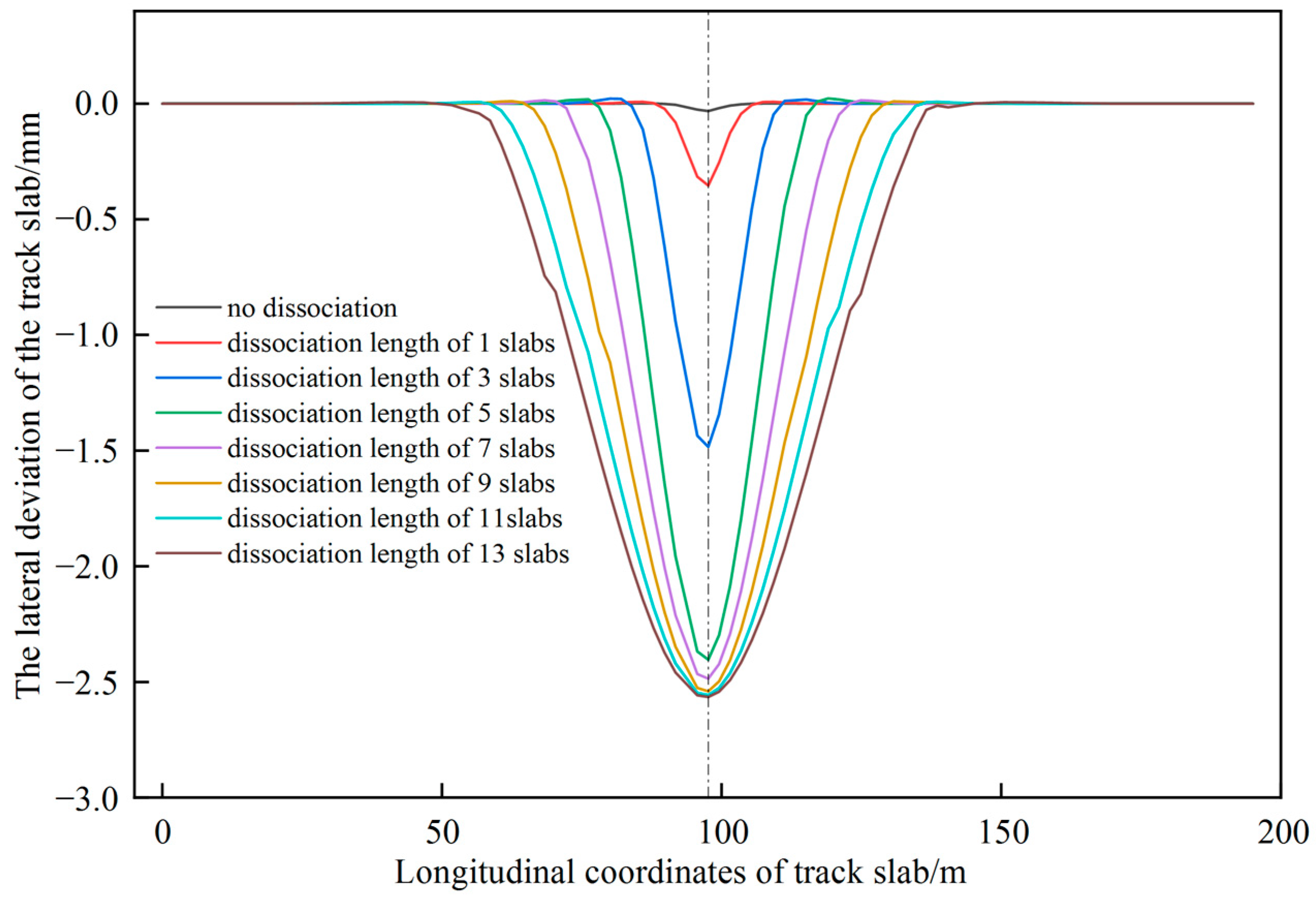
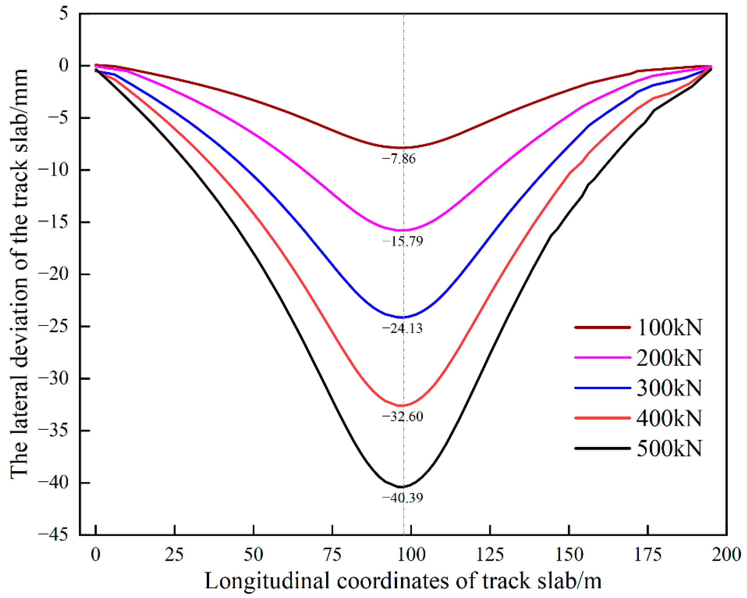
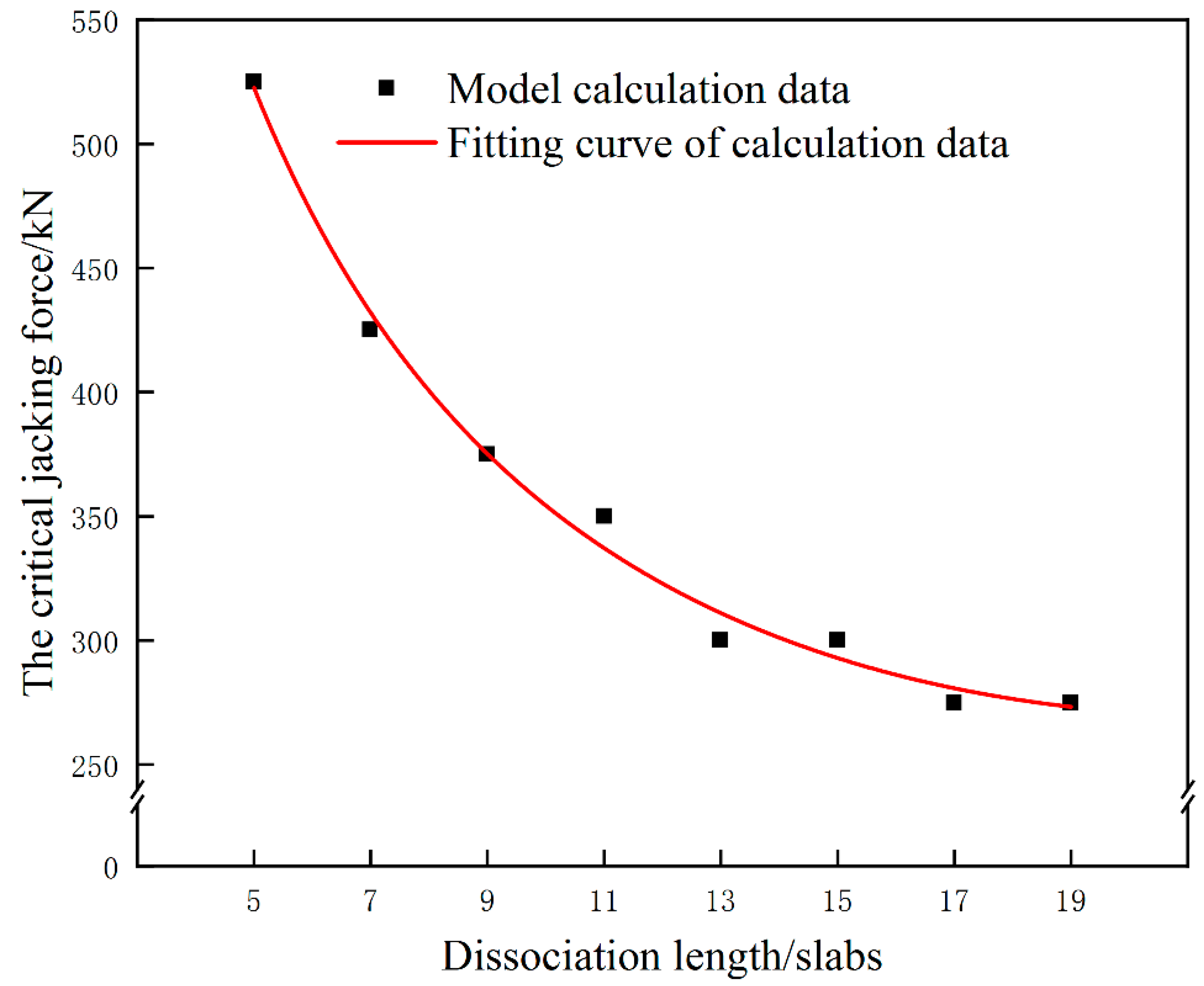
- For the CRTSII slab ballastless track in the single point jacking rectification, the deviation value increases with the increase of jacking force and the dissociation length. When the dissociation length exceeds 5 slabs, the influence of the dissociation length on the deviation is significantly weakened. For avoiding the damage of interface between the mortar layer and the wide-narrow joint, the jacking force should be smaller than 375 kN in some conditions.
- In the process of multi-point jacking, the deviation value is also related to the jacking force and the dissociation length. When the jacking loading length equals to 5 slabs, The relationship between the deviation and the jacking force can be described as . For avoiding the damage of interface between the mortar layer and the wide-narrow joint, the jacking force should be smaller than 275 kN in above condition, and the lateral deviation will be smaller than 22.11 mm.
- The acceleration of the track slab caused by the train in the dissociation condition is large, and has a significant increase with the increase of the train speed. The acceleration of the track slab has a significant decrease with the application and enhancement of the temporary restraint. It is necessary to restrict the speed of passing trains to no more than 150 km/h during the jacking rectification fixing for dissociation condition without temporary restraint.
- The train speed in the range of 100 km/h–350 km/h has very little effect on the vertical displacement of the track slab and the subgrade bed surface under the four operating conditions.
Author Contributions
Funding
Institutional Review Board Statement
Informed Consent Statement
Data Availability Statement
Conflicts of Interest
References
- Zhu, G.M. Research and application of ballastless track at home and abroad. J. Railw. Eng. Soc. 2008, 7, 28–30. [Google Scholar]
- Sun, L.; Chen, L.; Zelelew, H.H. Stress and Deflection Parametric Study of High-Speed Railway CRTS-II Ballastless Track Slab on Elevated Bridge Foundations. J. Traffic Trans. Eng. 2013, 139, 1224–1234. [Google Scholar] [CrossRef]
- Li, Y.; Cen, M.; Zhang, Q. A method of integer programming for track fine adjustment. In Proceedings of the 6th International Conference on Electronics and Information Engineering, Dalian, China, 26 September 2015; p. 97940D. [Google Scholar]
- Tan, S.H. Research on the progress of alignment rectification technology for ballastless track of high-speed railway. J. Railw. Sci. Eng. 2018, 15, 310–318. [Google Scholar]
- Liu, Y.; Xu, Q.; Sun, X.; Yang, G.; Zhao, G. Push Plate Test of CRTS II Slab Ballastless Track: Theoretical Analysis, Experiments, and Numerical Simulation. Shock Vib. 2021, 2021, 1945385. [Google Scholar] [CrossRef]
- Wen, X.H. Research on deviation correction technology of CRTS II slab ballastless track of high-speed railway. Railw. Surv. 2017, 43, 6–9. [Google Scholar]
- Wang, Q.; Zeng, H.; Jiang, T. Influence of subgrade defects on vibrational characteristics of ballastless track subgrade of high-speed railway. In Proceedings of the 2015 4th International Conference on Sustainable Energy and Environmental Engineering, Shenzhen, China, 20–21 December 2015; pp. 1–7. [Google Scholar]
- Cui, X.; Guo, G.; Du, B.; Cai, X.; Zhou, R. Effects of lateral differential settlement of the subgrade on deformation behavior and damage evolution of CRTS II slab track. Eng. Fail. Anal. 2021, 129, 105674. [Google Scholar] [CrossRef]
- China Academy of Railway Sciences. Technical Regulations for Dynamic Acceptance for High-Speed Railways Construction; China Railway Publishing House: Beijing, China, 2013; ISBN 151-13-3856. [Google Scholar]
- Gou, H.; Liu, C.; Xie, R.; Bao, Y.; Zhao, L.; Pu, Q. Running safety of high-speed train on deformed railway bridges with interlayer connection failure. Steel Compos. Struct. 2021, 39, 261–274. [Google Scholar]
- Cui, X.; Zhou, R.; Guo, G.; Du, B.; Liu, H. Effects of train load and water on stress intensity factors of the crack in slab track. Constr. Build. Mater. 2021, 299, 124247. [Google Scholar] [CrossRef]
- Chen, M.; Sun, Y.; Zhu, S.; Zhai, W. Dynamic performance comparison of different types of ballastless tracks using vehicle-track-subgrade coupled dynamics model. Eng. Struct. 2021, 249, 113390. [Google Scholar] [CrossRef]
- Yu, Z.; Xie, Y.; Shan, Z.; Li, X. Fatigue Performance of CRTS Ⅲ Slab Ballastless Track Structure under High-speed Train Load Based on Concrete Fatigue Damage Constitutive. J. Adv. Concr. Technol. 2018, 16, 233–249. [Google Scholar] [CrossRef] [Green Version]
- Cai, X.P.; Luo, B.C.; Zhong, Y.L.; Zhang, Y.R.; Hou, B.W. Arching mechanism of the slab joints in CRTSII slab track under high temperature conditions. Eng. Fail. Anal. 2019, 98, 95–108. [Google Scholar] [CrossRef]
- Huang, Y.C.; Gao, L.; Zhong, Y.L.; Zhou, C.Y. Study on the damage evolution of the joint and the arching deformation of CRTS-II ballastless slab track under complex temperature loading. Constr. Build. Mater. 2021, 22, 0950-0618. [Google Scholar] [CrossRef]
- Li, Y.; Chen, J.J.; Wang, J.X.; Shi, X.F.; Chen, L. Analysis of Damage of Joints in CRTSII Slab Track under Temperature and Vehicle Loads. Ksce. J. Civ. Eng. 2020, 24, 1209–1218. [Google Scholar] [CrossRef]
- Zhang, J.W.; Zhu, S.Y.; Cai, C.B.; Wang, M.Z.; Li, H.L. Experimental and numerical analysis on concrete interface damage of ballastless track using different cohesive models. Constr. Build. Mater. 2020, 263, 120859. [Google Scholar] [CrossRef]
- Li, X.; Chen, J. An extended cohesive damage model for simulating arbitrary damage propagation in engineering materials. Comput. Methods Appl. Mech. Eng. 2017, 315, 744–759. [Google Scholar] [CrossRef] [Green Version]
- Fan, S.C. Study on the Dynamic Response of High-Speed Railway Track and Foundation. Master’s Thesis, China University of Mining & Technology, Beijing, China, 2018. [Google Scholar]
- Li, L.; Nimbalkar, S.; Zhong, R. Finite element model of ballasted railway with infinite boundaries considering effects of moving train loads and Rayleigh waves. Soil Dyn. Earthq. Eng. 2018, 114, 147–153. [Google Scholar] [CrossRef]
- Lei, X.; Zhang, B. Analysis of Dynamic Behavior for Slab Track of High-Speed Railway Based on Vehicle and Track Elements. J. Transp. Eng. 2011, 137, 227–240. [Google Scholar] [CrossRef]
- Palomo, M.L.; Barcelo, F.R.; Llario, F.R.; Herraiz, J.R. Effect of vehicle speed on the dynamics of track transitions. J. Vib. Control. 2018, 24, 5118–5128. [Google Scholar]
- Xu, J.D. High-speed railway ballastless track bridge corrective construction train operation conditions and transition measures. Hi-Speed Railw. Bridge Tunn. Detect. Maint. Semin. 2019, 11, 17–24. [Google Scholar]
- Ruan, Q.W. Research on the Damage Characteristics of CRTS II Slab Track under Temperature and Train. Master’s Thesis, Beijing Jiaotong University, Beijing, China, 2018. [Google Scholar]
- Liang, Y.K. Research on Deformation Characteristics and Dynamic Influence of CRTS III Slab Ballastless Track under Subgrade Frost Heaving. Master’s Thesis, Beijing Jiaotong University, Beijing, China, 2018. [Google Scholar]
- Jian, W.; Ping, W.; Dao-lin, M. Matching performance of CHN60N rail with various wheel profiles for Chinese high-speed railway. IOP Conf. Ser. Mater. Sci. Eng. 2018, 383, 12041. [Google Scholar] [CrossRef]
- Liu, J.; Pan, Y.J.; Yang, Y.Q. Research on the mechanical behavior and key parameters of ballastless track under jacking rectification. J. Beijing Jiaotong Univ. 2021, 45, 23–31. [Google Scholar]
- Ramamurthi, M.; Lee, J.; Yang, S.; Kim, Y. Delamination characterization of bonded interface in polymer coated steel using surface based cohesive model. Int. J. Precis. Eng. Manuf. 2013, 14, 1755–1765. [Google Scholar] [CrossRef]
- de Borst, R. Numerical aspects of cohesive-zone models. Eng. Fract. Mech. 2003, 70, 1743–1757. [Google Scholar] [CrossRef]
- Xu, Y.D.; Yan, D.B.; Qiu, J.X. The damage expansion law of CRTS II slab track on subgrade. J. Tongji Univ. Nat. Sci. Ed. 2019, 47, 824–831. [Google Scholar]
- Zhong, Y.L.; Gao, L.; Wang, P. Shear failure mechanism of interface between CRTS II track slab and CA mortar under temperature load. Eng. Mech. 2018, 35, 230–238. [Google Scholar]
- Zhou, M.; Dai, G.L. Study on the stability of longitudinal slab ballastless track on simply supported high-speed railway bridges. J. Railw. 2015, 37, 60–65. [Google Scholar]
- Bian, X.C.; Chen, Y.M. Dynamic response analysis of track and foundation under train load. J. Mech. 2005, 4, 477–484. [Google Scholar]
- Ma, L.H.; Liang, Q.H.; Gu, A.J. The vibration test and numerical analysis of subgrade section of Shanghai-Nanjing intercity high-speed railway. J. Railw. 2014, 36, 88–93. [Google Scholar]
- The Third Railway Survey and Design Institute Group Co., Ltd. Code for Design of High-Speed Railway; China Railway Publishing House: Beijing, China, 2014; ISBN 115-13-4283. [Google Scholar]
- Tian, J.J. Research on Dynamic Response of Subgrade under High-Speed Train Load. Master’s Thesis, Xi’an University of Architecture and Technology, Xi’an, China, 2017. [Google Scholar]
- Cai, X.P. Dynamic characteristics of train ballastless track under the conditions of differential settlement of subgrade. In Advances in Environmental Vibration-Proceedings of the 5th International Symposium on Environmental Vibration; ISEV: Lyon, France, 2011; pp. 647–652. [Google Scholar]
- Zhu, X.Y.; Cai, D.G.; Qi, Z.G. High-speed railway ballastless track subgrade arch regulation technology. Railw. Constr. 2018, 58, 87–89, 94. [Google Scholar]
- Fu, B.X.; Shi, C.L.; Ma, W.B. Dynamic response analysis of slab track of passenger dedicated line. J. Railw. Eng. 2009, 26, 48–53. [Google Scholar]


| Track Components | Size (mm) | Elastic Modulus (GPa) | Poisson’s Ratio | Density (kg/m3) |
|---|---|---|---|---|
| Track slab | 6450 × 2550 × 200 | 36 | 0.2 | 2500 |
| Mortar layer | 2550 × 30 | 7 | 0.2 | 1950 |
| Base plate | 3250 × 300 | 22 | 0.2 | 2500 |
| Rail bearing platform | 500 × 250 × 60 | 36 | 0.2 | 2500 |
| Wide joint | 210 × 100 | 36 | 0.2 | 2500 |
| Narrow joint | 50 × 100 | 36 | 0.2 | 2500 |
| Rebar | ∅20 | 210 | 0.3 | 7800 |
| Rail | CHN60 | 210 | 0.3 | 7830 |
| Name | Thickness/m | Weight/(kN/m3) | Modulus of Elasticity/GPa | Poisson’s Ratio | Cohesion/kPa | Angle of Internal Friction/(°) |
|---|---|---|---|---|---|---|
| Surface of subgrade bed | 0.4 | 19.5 | 0.25 | 0.3 | 32 | 32 |
| Bottom of subgrade bed | 2.3 | 19.0 | 0.20 | 0.3 | 26 | 25 |
| The body of the subgrade | 1.8 | 18.5 | 0.15 | 0.28 | 25 | 23 |
| Parameters | Numeric Value | Parameters | Numeric Value |
|---|---|---|---|
| Marshalling type/carriage | 8 | Total length (m) | 203.0 |
| Bogie shafts (m) | 2.5 | Axle load (t) | ≤15 |
| Intermediate vehicle length (m) | 25.0 | Steering rack center distance (m) | 17.5 |
Publisher’s Note: MDPI stays neutral with regard to jurisdictional claims in published maps and institutional affiliations. |
© 2022 by the authors. Licensee MDPI, Basel, Switzerland. This article is an open access article distributed under the terms and conditions of the Creative Commons Attribution (CC BY) license (https://creativecommons.org/licenses/by/4.0/).
Share and Cite
Chen, W.; Wang, C.; Fang, L.; Liu, C.; Zeng, Z.; Lou, P.; Zhang, T. Line Shape Analysis and Dynamic Response of Ballastless Track during Jacking Rectification Fixing. Materials 2022, 15, 8265. https://doi.org/10.3390/ma15228265
Chen W, Wang C, Fang L, Liu C, Zeng Z, Lou P, Zhang T. Line Shape Analysis and Dynamic Response of Ballastless Track during Jacking Rectification Fixing. Materials. 2022; 15(22):8265. https://doi.org/10.3390/ma15228265
Chicago/Turabian StyleChen, Wei, Chao Wang, Linhong Fang, Chao Liu, Zhiping Zeng, Ping Lou, and Tianqi Zhang. 2022. "Line Shape Analysis and Dynamic Response of Ballastless Track during Jacking Rectification Fixing" Materials 15, no. 22: 8265. https://doi.org/10.3390/ma15228265