
Investigating Residual Stresses in Metal-Plastic Composites Stiffening Ribs Formed Using the Single Point Incremental Forming Method

 ,
,  , , , and
Abstract
:1. Introduction
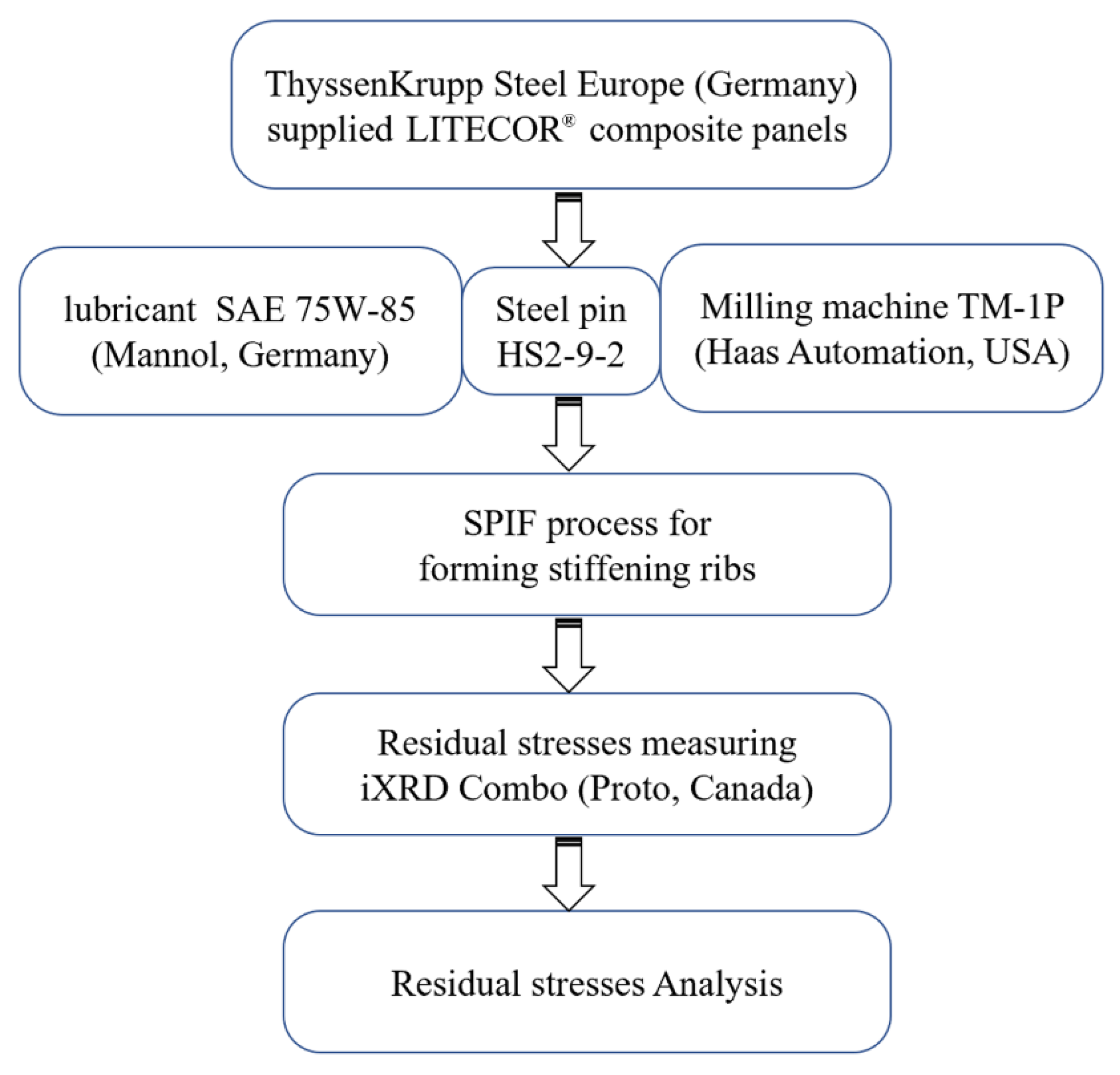
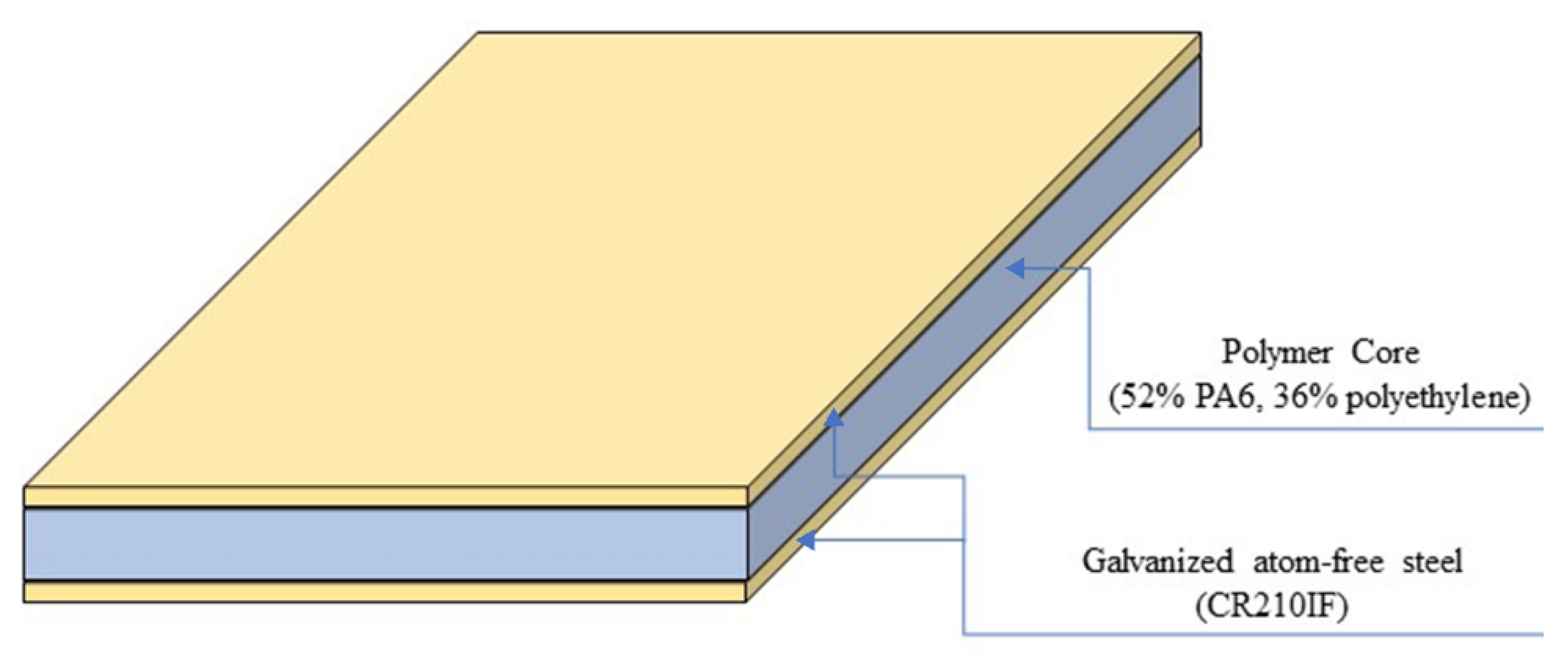
2. Materials and Methods
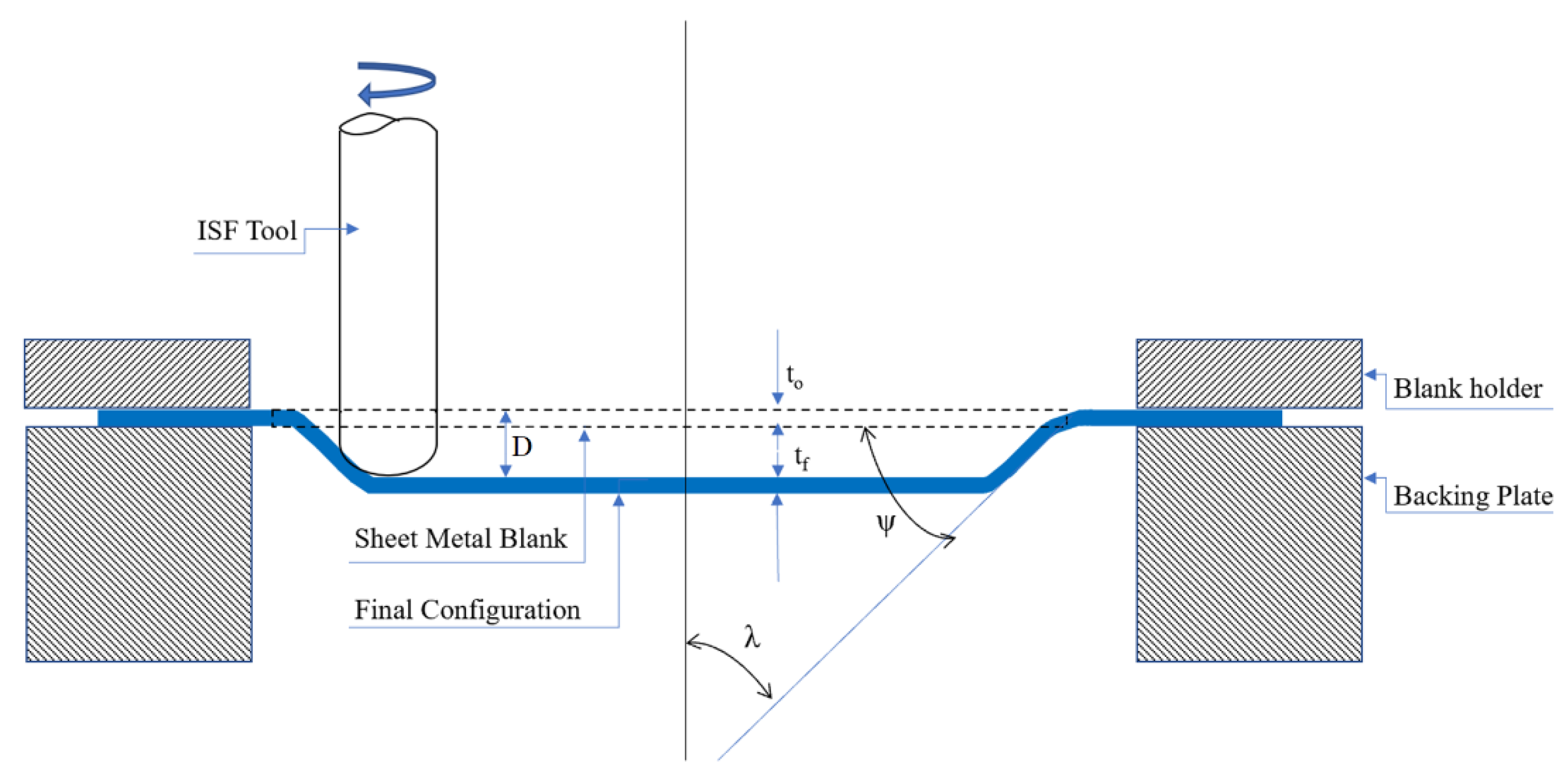
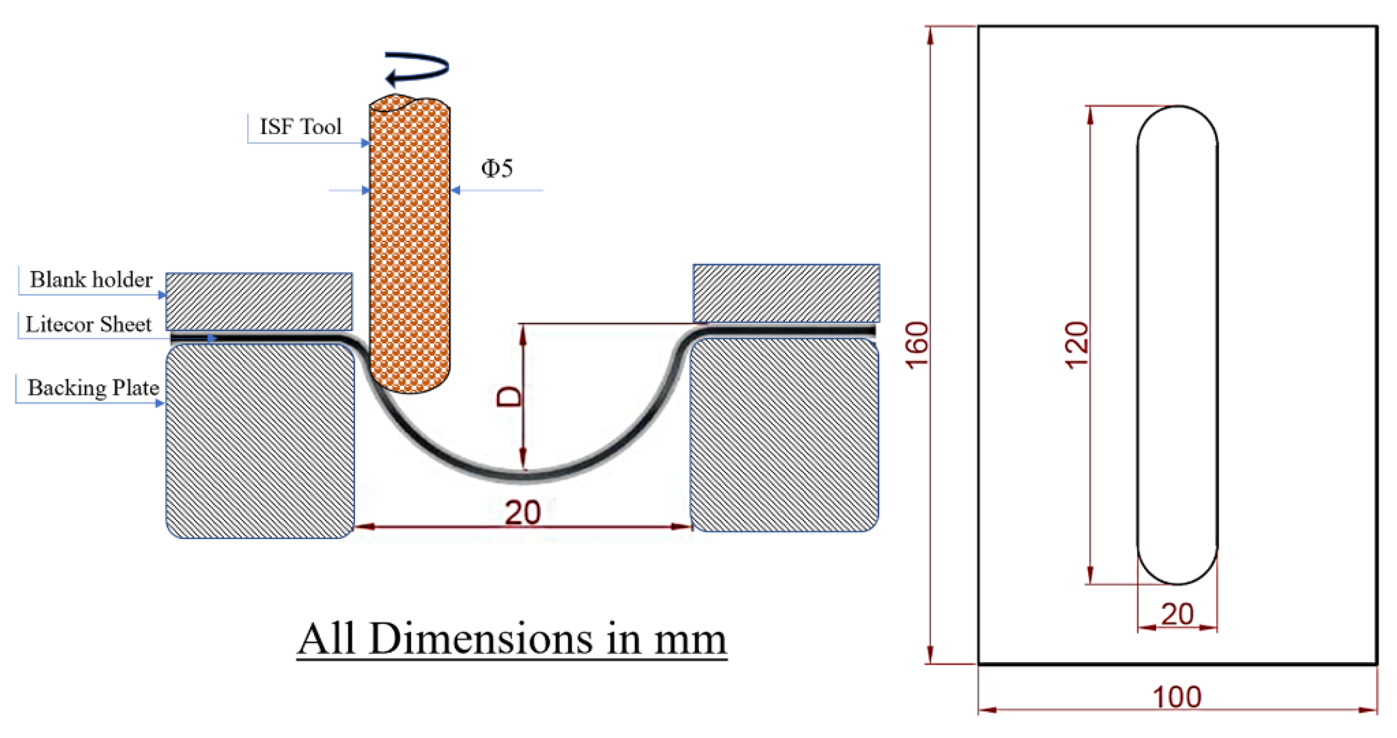
2.1. Incremental Forming
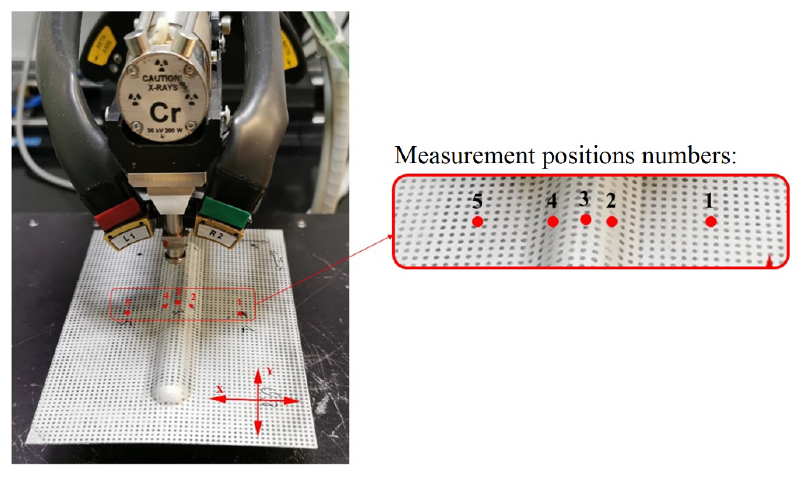
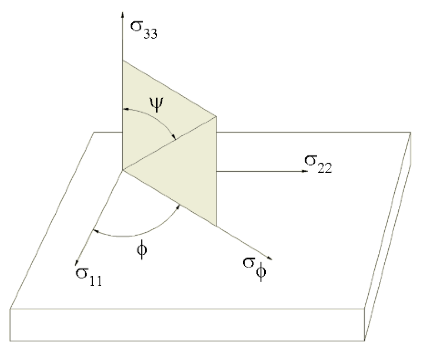
2.2. X-ray Diffraction Analysis
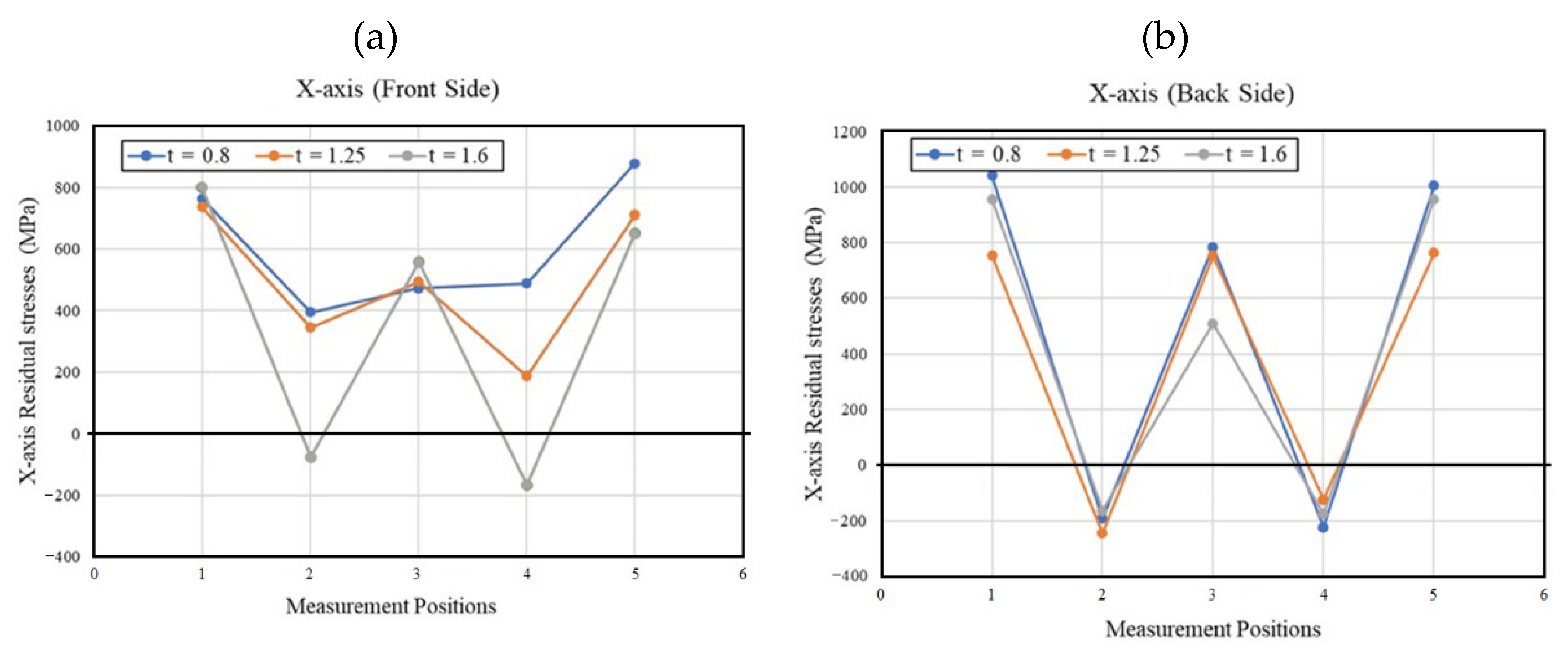
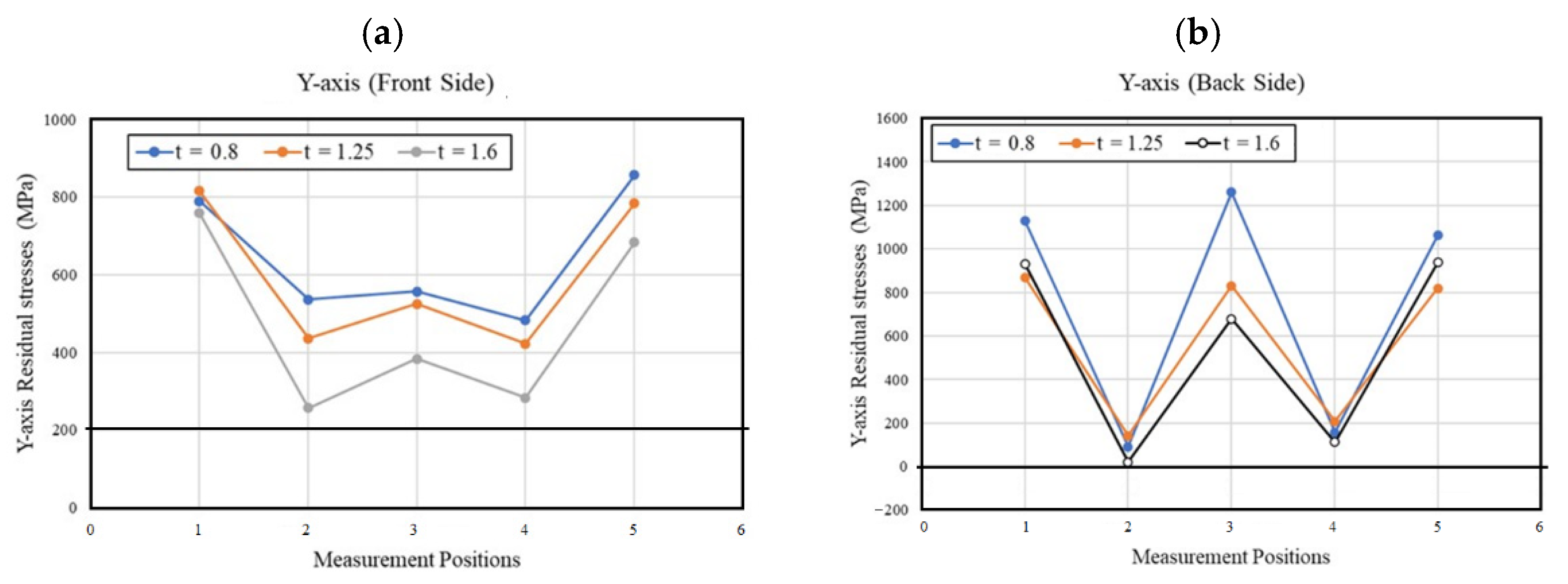
3. Results and Discussions
4. Conclusions
Author Contributions
Funding
Institutional Review Board Statement
Informed Consent Statement
Data Availability Statement
Conflicts of Interest
References
- Gu, H.; Liu, C.; Zhu, J.; Gu, J.; Wujcik, E.K.; Shao, L.; Wang, N.; Wei, H.; Scaffaro, R.; Zhang, J.; et al. Introducing advanced composites and hybrid materials. Adv. Compos. Hybrid Mater. 2017, 1, 1–5. [Google Scholar] [CrossRef] [Green Version]
- Advantages and Disadvantages of Using Composite Materials in Airplanes. Available online: https://www.thebalancecareers.com/composite-materials-aircraft-structure-282777 (accessed on 24 October 2022).
- Kubit, A.; Trzepieciński, T.; Krasowski, B.; Slota, J.; Spišák, E. Strength Analysis of a Rib-Stiffened GLARE-Based Thin-Walled Structure. Materials 2020, 13, 2929. [Google Scholar] [CrossRef] [PubMed]
- Ilyas, R.; Sapuan, S.; Asyraf, M.; Dayana, D.; Amelia, J.; Rani, M.; Norrrahim, M.; Nurazzi, N.; Aisyah, H.; Sharma, S.; et al. Polymer Composites Filled with Metal Derivatives: A Review of Flame Retardants. Polymers 2021, 13, 1701. [Google Scholar] [CrossRef] [PubMed]
- Wong, W.-K.; Lai, C.-H.N.; Cheng, W.-Y.; Tung, L.-H.; Chang, R.C.-C.; Leung, F.K.-C. Polymer–Metal Composite Healthcare Materials: From Nano to Device Scale. J. Compos. Sci. 2022, 6, 218. [Google Scholar] [CrossRef]
- Bloor, D.; Donnelly, K.; Hands, P.J.; Laughlin, P.; Lussey, D. A metal–polymer composite with unusual properties. J. Phys. D Appl. Phys. 2005, 38, 2851–2860. [Google Scholar] [CrossRef]
- Contreiras, T.R.M. Joining by Forming of Composite Sandwich Panels. Master’s Thesis, Superior Técnico, Lisboa, Portugal, 2019. Available online: https://fenix.tecnico.ulisboa.pt/downloadFile/1126295043836505/Thesis.pdf (accessed on 27 October 2022).
- Kustroń, P.; Korzeniowski, M.; Piwowarczyk, T.; Sokołowski, P. Development of Resistance Spot Welding Processes of Metal–Plastic Composites. Materials 2021, 14, 3233. [Google Scholar] [CrossRef] [PubMed]
- Al Naimi, I.K.A. Weldability of new material sandwich steel for automotive applications. Al-Khwarizmi Eng. J. 2016, 12, 60–78. [Google Scholar]
- Contreiras, T.; Pragana, J.; Bragança, I.; Silva, C.; Alves, L.; Martins, P. Joining by forming of lightweight sandwich composite panels. Procedia Manuf. 2019, 29, 288–295. [Google Scholar] [CrossRef]
- Pragana, J.; Contreiras, T.R.; Bragança, I.; Silva, C.; Alves, L.; Martins, P.A. Joining by forming of metal–polymer sandwich composite panels. Proc. Inst. Mech. Eng. Part B J. Eng. Manuf. 2018, 233, 2089–2098. [Google Scholar] [CrossRef]
- Wendel, E. Evaluation of Potential for Metal/Polymer/Metal Sandwich Material as Outer Panels for Trucks. 2019. Available online: http://www.diva-portal.org/smash/get/diva2:1300622/FULLTEXT02.pdf (accessed on 19 October 2022).
- Trzepieciński, T.; Kubit, A.; Slota, J. Assessment of the Tribological Properties of the Steel/Polymer/Steel Sandwich Material LITECOR. Lubricants 2022, 10, 99. [Google Scholar] [CrossRef]
- Song, S.; Zang, H.; Duan, N.; Jiang, J. Experimental Research and Analysis on Fatigue Life of Carbon Fiber Reinforced Polymer (CFRP) Tendons. Materials 2019, 12, 3383. [Google Scholar] [CrossRef]
- Song, Y.; Ding, Y.; Jiang, F.; Wang, Z.; Jia, H.; Chen, Z.; Xu, C.; Ge, J. Fatigue Performance of CFRP-Strengthened Rib-to-Diaphragm Welded Details of Orthotropic Steel Decks: Experimental and Numerical Evaluation. Adv. Civ. Eng. 2022, 2022, 1–12. [Google Scholar] [CrossRef]
- Davoodi, M.M.; Sapuan, S.M.; Ali, A.; Ahmad, D. Effect of the strengthened ribs in hybrid toughened kenaf/ glass epoxy composite bumper beam. Life Sci. J. 2012, 9, 210–213. [Google Scholar]
- Cao, T.; Lu, B.; Xu, D.; Zhang, H.; Chen, J.; Long, H.; Cao, J. An efficient method for thickness prediction in multi-pass incremental sheet forming. Int. J. Adv. Manuf. Technol. 2014, 77, 469–483. [Google Scholar] [CrossRef] [Green Version]
- Ingarao, G.; Di Lorenzo, R.; Micari, F. Sustainability issues in sheet metal forming processes: An overview. J. Clean. Prod. 2011, 19, 337–347. [Google Scholar] [CrossRef]
- Ambrogio, G.; Filice, L.; Gagliardi, F. Formability of lightweight alloys by hot incremental sheet forming. Mater. Des. 2012, 34, 501–508. [Google Scholar] [CrossRef]
- Ambrogio, G.; De Napoli, L.; Filice, L.; Gagliardi, F.; Muzzupappa, M. Application of Incremental Forming process for high customised medical product manufacturing. J. Mater. Process. Technol. 2005, 162–163, 156–162. [Google Scholar] [CrossRef]
- Arshad, S. Single Point Incremental Forming: A Study of Forming Parameters, Forming Limits and Part Accuracy of Aluminium 2024, 6061 and 7475 Alloys. Master’s Thesis, Stockholm, Sweden, 2012. Available online: https://www.diva-portal.org/smash/record.jsf?pid=diva2%3A557935&dswid=9749 (accessed on 25 October 2022).
- Ai, S.; Lu, B.; Chen, J.; Long, H.; Ou, H. Evaluation of deformation stability and fracture mechanism in incremental sheet forming. Int. J. Mech. Sci. 2017, 124–125, 174–184. [Google Scholar] [CrossRef]
- Silva, M.B.; Skjoedt, M.; Atkins, A.G.; Bay, N.; Martins, P. Single-point incremental forming and formability—Failure diagrams. J. Strain Anal. Eng. Des. 2008, 43, 15–35. [Google Scholar] [CrossRef]
- Krasowski, B.; Kubit, A.; Trzepieciński, T.; Dudek, K.; Slota, J. Application of X-ray Diffraction for Residual Stress Analysis in Truncated Cones Made by Incremental Forming. Adv. Sci. Technol. Res. J. 2020, 14, 103–111. [Google Scholar] [CrossRef]
- Trzepieciński, T.; Kubit, A.; Dzierwa, A.; Krasowski, B.; Jurczak, W. Surface Finish Analysis in Single Point Incremental Sheet Forming of Rib-Stiffened 2024-T3 and 7075-T6 Alclad Aluminium Alloy Panels. Materials 2021, 14, 1640. [Google Scholar] [CrossRef] [PubMed]
- Kubit, A.; Korzeniowski, M.; Bobusia, M.; Ochałek, K.; Slota, J. Analysis of the Possibility of Forming Stiffening Ribs in Litecor Metal-Plastic Composite Using the Single Point Incremental Forming Method. Key Eng. Mater. 2022, 926, 802–814. [Google Scholar] [CrossRef]
- Maaß, F.; Gies, S.; Dobecki, M.; Brömmelhoff, K.; Tekkaya, A.E.; Reimers, W. Analysis of residual stress state in sheet metal parts processed by single point incremental forming. In Proceedings of the AIP Conference Proceedings, Palermo, Italy, 23–25 April 2018; Volume 1960, p. 160017. [Google Scholar]
- Ambrogio, G.; Cozza, V.; Filice, L.; Micari, F. An analytical model for improving precision in single point incremental forming. J. Mater. Process. Technol. 2007, 191, 92–95. [Google Scholar] [CrossRef]
- Micari, F.; Ambrogio, G.; Filice, L. Shape and dimensional accuracy in Single Point Incremental Forming: State of the art and future trends. J. Mater. Process. Technol. 2007, 191, 390–395. [Google Scholar] [CrossRef]
- Bambach, M.; Taleb Araghi, B.; Hirt, G. Strategies to improve the geometric accuracy in asymmetric single point incremental forming. Prod. Eng. 2009, 3, 145–156. [Google Scholar] [CrossRef]
- Huber, N.; Heerens, J. On the effect of a general residual stress state on indentation and hardness testing. Acta Mater. 2008, 56, 6205–6213. [Google Scholar] [CrossRef] [Green Version]
- Radu, C.; Herghelegiu, E.; Tampu, N.C.; Cristea, I. The Residual Stress State Generated by Single Point Incremental Forming of Aluminum Metal Sheets. Appl. Mech. Mater. 2013, 371, 148–152. [Google Scholar] [CrossRef]
- Radu, C.; Tampu, C.; Cristea, I.; Chirita, B. The Effect of Residual Stresses on the Accuracy of Parts Processed by SPIF. Mater. Manuf. Process. 2013, 28, 572–576. [Google Scholar] [CrossRef]
- Abdulrazaq, M.M.; Gazi, S.K.; Ibraheem, M.Q. Investigation the Influence of SPIF Parameters on Residual Stresses for Angular Surfaces Based on Iso-Planar Tool Path. Al-Khwarizmi Eng. J. 2019, 15, 50–59. [Google Scholar] [CrossRef] [Green Version]
- Shi, X.; Hussain, G.; Butt, S.I.; Song, F.; Huang, D.; Liu, Y. The state of residual stresses in the Cu/Steel bonded laminates after ISF deformation: An experimental analysis. J. Manuf. Process. 2017, 30, 14–26. [Google Scholar] [CrossRef]
- Hajavifard, R.; Maqbool, F.; Schmiedt-Kalenborn, A.; Buhl, J.; Bambach, M.; Walther, F. Integrated Forming and Surface Engineering of Disc Springs by Inducing Residual Stresses by Incremental Sheet Forming. Materials 2019, 12, 1646. [Google Scholar] [CrossRef] [PubMed] [Green Version]
- Maqbool, F.; Bambach, M. Experimental and Numerical Investigation of the Influence of Process Parameters in Incremental Sheet Metal Forming on Residual Stresses. J. Manuf. Mater. Process. 2019, 3, 31. [Google Scholar] [CrossRef]
- Maaß, F.; Hahn, M.; Dobecki, M.; Thannhäuser, E.; Tekkaya, A.E.; Reimers, W. Influence of tool path strategies on the residual stress development in single point incremental forming. Procedia Manuf. 2019, 29, 53–58. [Google Scholar] [CrossRef]
- Tanaka, S.; Nakamura, T.; Hayakawa, K.; Nakamura, H.; Motomura, K. Residual Stress in Sheet Metal Parts Made by Incremental Forming Process. AIP Conf. Proc. 2007, 908, 775–780. [Google Scholar] [CrossRef]
- Slota, J.; Krasowski, B.; Kubit, A.; Trzepiecinski, T.; Bochnowski, W.; Dudek, K.; Neslušan, M. Residual Stresses and Surface Roughness Analysis of Truncated Cones of Steel Sheet Made by Single Point Incremental Forming. Metals 2020, 10, 237. [Google Scholar] [CrossRef] [Green Version]
- Slota, J.; Kubit, A.; Trzepieciński, T.; Krasowski, B.; Varga, J. Ultimate Load-Carrying Ability of Rib-Stiffened 2024-T3 and 7075-T6 Aluminium Alloy Panels under Axial Compression. Materials 2021, 14, 1176. [Google Scholar] [CrossRef] [PubMed]
- Krasowski, B.; Kubit, A.; Trzepieciński, T.; Slota, J. Experimental Analysis of Single Point Incremental Forming of Truncated Cones in DC04 Steel Sheet. Adv. Mater. Sci. 2020, 20, 5–15. [Google Scholar] [CrossRef]
- Guo, J.; Fu, H.; Pan, B.; Kang, R. Recent progress of residual stress measurement methods: A review. Chin. J. Aeronaut. 2021, 34, 54–78. [Google Scholar] [CrossRef]
- Kocurek, P. Analiza stanu naprężeń własnych w odlewach segmentu aparatu kierującego turbiny silników lotniczych. Inżynieria Mater. 2015, 1, 31–35. [Google Scholar] [CrossRef]
- Eigenmann, B.; Macherauch, E. Determination of inhomogeneous residual stress states in surface layers of machined engineering ceramics by synchrotron X-rays. Nucl. Instrum. Methods Phys. Res. Sect. B Beam Interact. Mater. Atoms 1995, 97, 92–97. [Google Scholar] [CrossRef]
- Jiménez, I.; López, C.; Martinez-Romero, O.; Mares, P.; Siller, H.R.; Diabb, J.; Sandoval-Robles, J.A.; Elías-Zúñiga, A. Investigation of residual stress distribution in single point incremental forming of aluminum parts by X-ray diffraction technique. Int. J. Adv. Manuf. Technol. 2017, 91, 2571–2580. [Google Scholar] [CrossRef]


| Properties | Unit | Value |
|---|---|---|
| Yield Strength | MPa | 120–180 |
| Ultimate Tensile Strength | MPa | 190–240 |
| Elongation | % | 28 |
| Location | Front Side Residual Stresses for X-Axes (MPa) | Front Side Residual Stresses for Y-Axes (MPa) | ||||
|---|---|---|---|---|---|---|
| t = 0.8 | t = 1.25 | t = 1.6 | t = 0.8 | t = 1.25 | t = 1.6 | |
| 1 | 765 | 736 | 801 | 790 | 816 | 759 |
| 2 | 395 | 345 | −75 | 536 | 436 | 257 |
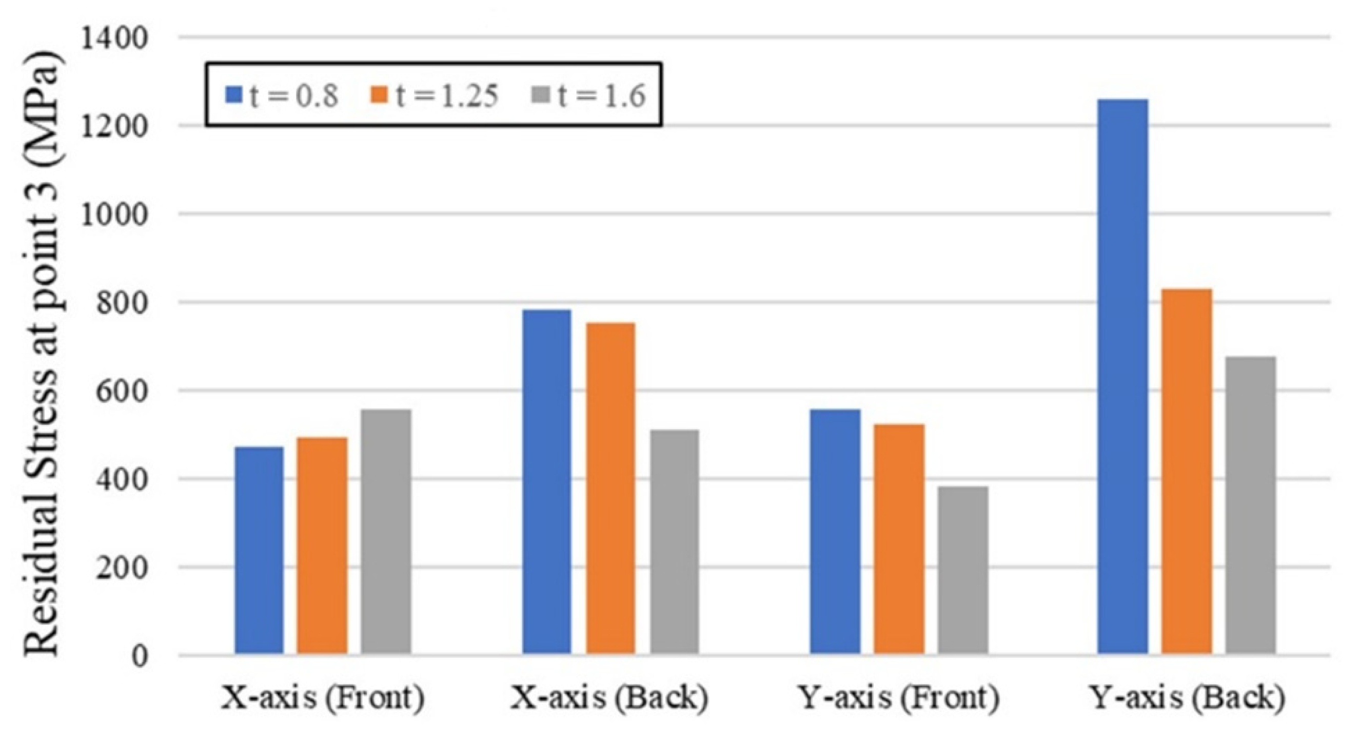
| 3 | 473 | 494 | 557 | 557 | 525 | 384 |
| 4 | 488 | 187 | −166 | 483 | 422 | 283 |
| 5 | 879 | 711 | 651 | 857 | 784 | 684 |
| Max | 879 | 736 | 801 | 857 | 816 | 759 |
| Location | Back Side Residual Stresses for X-Axes (MPa) | Back Side Residual Stresses for Y-Axes (MPa) | ||||
|---|---|---|---|---|---|---|
| t = 0.8 | t = 1.25 | t = 1.6 | t = 0.8 | t = 1.25 | t = 1.6 | |
| 1 | 1041 | 755 | 956 | 1130 | 869 | 932 |
| 2 | −193 | −246 | −164 | 92 | 141 | 21 |
| 3 | 784 | 753 | 509 | 1260 | 830 | 678 |
| 4 | −224 | −124 | −176 | 158 | 208 | 112 |
| 5 | 1004 | 762 | 957 | 1062 | 819 | 937 |
| Max | 1041 | 762 | 957 | 1260 | 869 | 937 |
| Point Analyzed | Percentage Weight Concentration (%) | |
|---|---|---|
| Zn | Fe | |
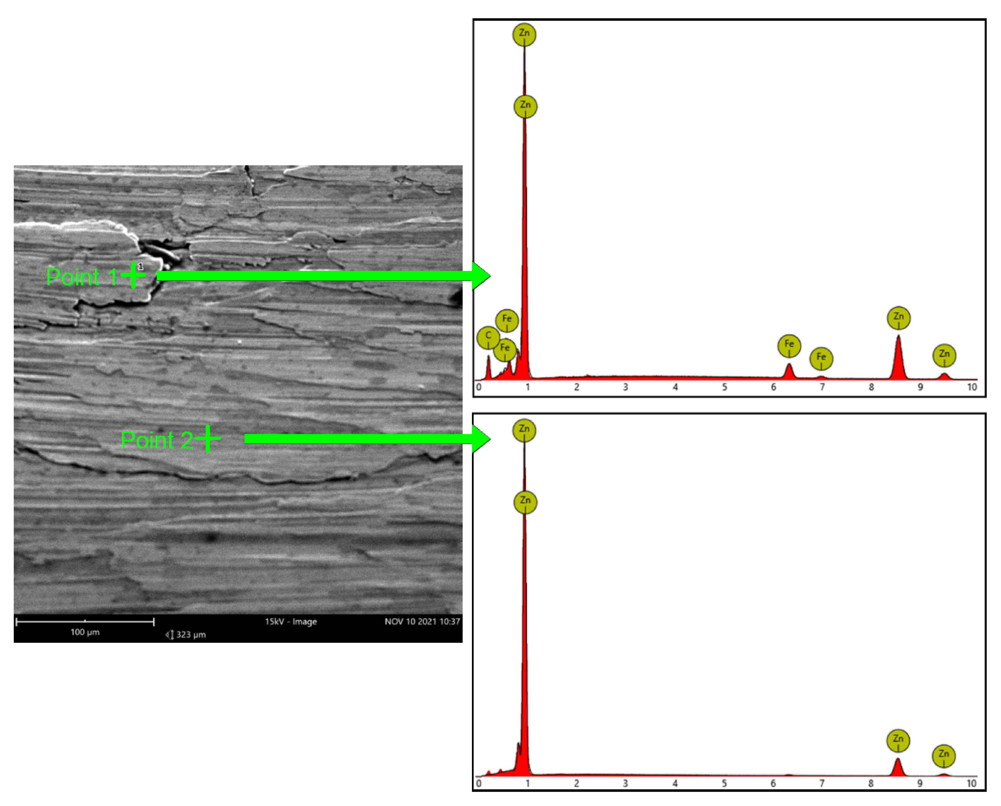
| Point 1 | 87.91 | 12.09 |
| Point 2 | 100 | - |
Publisher’s Note: MDPI stays neutral with regard to jurisdictional claims in published maps and institutional affiliations. |
© 2022 by the authors. Licensee MDPI, Basel, Switzerland. This article is an open access article distributed under the terms and conditions of the Creative Commons Attribution (CC BY) license (https://creativecommons.org/licenses/by/4.0/).
Share and Cite
Kubit, A.; Al-Sabur, R.; Gradzik, A.; Ochał, K.; Slota, J.; Korzeniowski, M. Investigating Residual Stresses in Metal-Plastic Composites Stiffening Ribs Formed Using the Single Point Incremental Forming Method. Materials 2022, 15, 8252. https://doi.org/10.3390/ma15228252
Kubit A, Al-Sabur R, Gradzik A, Ochał K, Slota J, Korzeniowski M. Investigating Residual Stresses in Metal-Plastic Composites Stiffening Ribs Formed Using the Single Point Incremental Forming Method. Materials. 2022; 15(22):8252. https://doi.org/10.3390/ma15228252
Chicago/Turabian StyleKubit, Andrzej, Raheem Al-Sabur, Andrzej Gradzik, Kamil Ochał, Ján Slota, and Marcin Korzeniowski. 2022. "Investigating Residual Stresses in Metal-Plastic Composites Stiffening Ribs Formed Using the Single Point Incremental Forming Method" Materials 15, no. 22: 8252. https://doi.org/10.3390/ma15228252