Article

Design Suggestions on Resistance from Flange of Sorbite Stainless Steel Plate Girder under Shear

1
School of Civil Engineering, Chongqing University, Chongqing 400045, China
2
Key Laboratory of New Technology for Construction of Cities in Mountain Area, Chongqing University, Ministry of Education, Chongqing 400045, China
3
School of Management Science and Real Estate, Chongqing University, Chongqing 400045, China
4
The Third Construction Limited Company of China Construction Third Engineering Bureau, Wuhan 430070, China
5
Key Laboratory of Civil Engineering Safety and Durability of China Education Ministry, Department of Civil Engineering, Tsinghua University, Beijing 100084, China
*
Author to whom correspondence should be addressed.
Materials 2022, 15(22), 8069; https://doi.org/10.3390/ma15228069
Submission received: 23 September 2022 / Revised: 1 November 2022 / Accepted: 4 November 2022 / Published: 15 November 2022

Abstract

:
A new S600E sorbite stainless steel (SS), which performs outstanding mechanical properties, was introduced in a plate girder to enhance the resistant performance and durability. The resistance from the flange for S600E sorbite SS plate girders developing post-buckling capacity was investigated through numerical analyses, which included the material and geometrical nonlinearity. The value of distance between plastic hinges performed significant effects on resistance from flange. There was a certain distribution range of the flange plastic hinge. Hence, it was difficult to determine the value of distance between plastic hinges accurately based merely on the failure behavior. Considering the theoretical basis of EN 1993-1-4: 2006+A1, the new methods to obtain resistance from the flange and determine the value of distance between the plastic hinges were proposed to avoid the aforementioned error. The parametric study was conducted to investigate the effect of key parameters on the resistance from the flange. To take the above effect into account, a correction factor was proposed for the design equation in EN 1993-1-4: 2006+A1 to predict the distance between flange plastic hinges accurately. The comparison was conducted to validate the accuracy of the proposed equations. The results indicated that the new modified equation could be used to predict the resistance from the flange of the S600E sorbite SS plate girder more accurately.

1. Introductions

Corrosion performed significant adverse effects on the durability of structures [1,2,3] (Figure 1). When structures were exposed to a corrosive environment, corrosion reduced the effective cross-section of structural and reinforcing steel obviously [4,5,6,7,8,9]. The durability of reinforced concrete structures and steel structures was reduced significantly [10,11]. Therefore, the stainless steel was widely used in structures to solve the above issue [12,13,14,15,16,17]. The stress–strain properties of stainless steel were different from those of carbon steel [18,19,20]. There was no yield plateau in the stainless steel curve [21]. The elastic segment of stainless steel was smaller than that of carbon steel [22]. Considering the above differences in stress–strain properties, the stainless steel component performed different resistant properties, compared with carbon steel components [22]. Many researchers paid attention to the aforementioned issue [15,23,24,25,26]. With increments in the development of stainless steel, the new S600E sorbite stainless steel (SS) realized quantitative production. Compared with the commonly used S30408 stainless steel, the S600E sorbite SS performed similar corrosion resistance. The strength properties of the S600E sorbite SS were better than those of S30408 stainless steel. Furthermore, the contents of precious metallic elements, such as Ni and Cr, of the S600E sorbite SS were lower than those of traditional stainless steel. Hence, the S600E sorbite SS’s price had an obvious competitive advantage [13]. Some researchers on the S600E sorbite SS stated the advantage for engineering applications [27,28]. However, the research on the S600E sorbite SS component was very limited. Considering outstanding corrosion resistance and strength properties, the innovative usage of S600E sorbite SS could bring beneficial effects on the durability and resistance of the component, especially when the plate thickness was relatively small.
The plate girder is an important component in bridge and industrial structures, and has an excellent load-resistant capacity. The plate girder is usually composed of flange, web, and transverse stiffener (Figure 2). To improve the resistant properties and reduce steel consumption, the thickness of the plate girder web is usually small. When the shear and patch loading were applied on the plate girder with a thin web, the post-buckling capacity occurred in the plate girder, which performed beneficial effects on resistant properties. Because of the post-buckling capacity, the ultimate resistance of the plate girder was not dependent on the buckling resistance but the mechanical properties of structural steel, which enabled the full utilization of material properties. Many researchers performed investigations on resistant properties of plate girders developing post-buckling capacity. Xiao et al. [29,30] studied the ultimate shear resistance of Q690 high-strength steel plate girder numerically. The results stated that with the increment in strength properties of structural steel, the ultimate shear resistance of the plate girder increased gradually. Nonlinear properties of structural steel also influenced the resistance properties of the plate girder. Hua et al. [7] revealed the residual resistance of Q690 high-strength steel plate girder under shear. The effects from the exposure temperature were reflected in the changes of stress–strain properties of structural steel, which were introduced in the plate girder numerical model. Numerical results indicated that the existence of yield plateau reduced the ultimate shear resistance of the plate girder. Saliba and Gardner [31] conducted experimental and numerical investigations on a lean duplex stainless steel plate girder under shear, and validated the equations in EN 1993-1-4+A1 [32]. It is worth noting that Xue et al. [28] clarified the ultimate shear resistance of the S600E sorbite SS plate girder. However, the distance between flange plastic hinges was determined on the failure mode of the plate girder model, which was not clear enough. The above current investigations on plate girders [33,34,35,36] stated that different mechanical properties resulted in differences in the resistant properties of the plate girder with a post-buckling capacity. It should be noted that the design methods in EN 1993-1-5 [37] came from investigations on the carbon steel plate girder [38], where the rotated stress field theory was proposed. Then, Olsson [39] and Saliba et al. [40] considered the nonlinear characteristics of stainless steel and proposed the modified design equations based on EN 1993-1-5 [37], which were included in EN 1993-1-4+A1 [32]. There were differences in the stress–strain properties between S600E sorbite SS and traditional stainless steel [27,28], which might result in differences in plate girder resistant properties. The current design equations might be inappropriate to predict the ultimate resistance of the S600E sorbite SS plate girder under shear, which limits the engineering application of the S600E sorbite SS. The research on the distance between flange plastic hinges was very limited, which was important for the resistance from the flange. A new method was proposed in this study to clarify the resistance from the flange. As a common research method, a finite element analysis has been widely used to study the bearing capacity and deformation of various engineering structures [41,42,43,44,45]. In this study, the series finite element analyses on the S600E sorbite SS plate girder under shear were conducted to clarify the advantage of the usage of the S600E sorbite SS. The effects of the strain hardening properties of structural steel on the resistant properties of the plate girder were discussed. After verification, the design equations in EN 1993-1-4+A1 [32] could not directly predict the resistance from the flange of S600E sorbite SS plate girders. Based on the parameter study, a new method was suggested to determine the resistance from flange. Then, the design equations in EN 1993-1-4+A1 [32] were modified to predict the resistance from the flange of the S600E sorbite SS plate girders accurately. The research in this study clarified the resistant properties of the S600E sorbite SS plate girder under shear. The design equations were suggested to quantify the ultimate shear resistance of the S600E sorbite SS plate girder, which performed the engineering significance.

2. Finite Element Analysis

2.1. Mechanical Property

To clarify the mechanical property of the S600E sorbite SS comprehensively, the comparison in stress–strain curves among S600E sorbite SS, S30408 austenitic stainless steel, Q235 mild steel, and Q690 high–strength steel was performed (Figure 3). The experimental results of S30408 austenitic stainless steel were obtained from [27]. The experimental results of Q235 mild steel and Q690 high-strength steel were obtained from [29]. It is clear to see that the Q690 high-strength steel performed the highest strength properties. There were clear elastic segments in the stress–strain curves of Q235 mild steel and Q690 high-strength steel. For the S600E sorbite SS and S30408 austenitic stainless steel, when the stress level was relatively low, there was plastic strain in the stress–strain curve. This phenomenon might be caused by differences in chemical composition (Table 1). It is worth noting that there was no yield plateau in the stress–strain curves of Q690 high-strength steel, S600E sorbite SS, and S30408 austenitic stainless steel [46,47]. It is worth noting that for the stress–strain curve without a clear yield plateau, the yield strength fy was the nominal stress corresponding to 0.2% proof stress [48,49,50]. The ductile properties of S600E sorbite SS were lower than those of Q690 high-strength steel. Because of the above differences in the stress–strain properties of the different structural steels, the current design equations for the traditional structural steel plate girder might not be applicable to the S600E sorbite SS plate girder. The true stress–strain properties were obtained from the engineering stress–strain properties. Considering that the necking phenomenon could be simulated by a numerical model appropriately, the true stress–strain properties should be introduced in a numerical model to achieve the better accuracy. It is worth noting that in Section 2.5, the elastic-perfectly plastic stress–strain curve was used to clarify the effects of the strain hardening effect on the resistant properties of the S600E sorbite SS plate girder. Except the discussion in Section 2.5, the true stress–strain curve of S600E sorbite SS was considered to be the constitutive model of the numerical analysis.

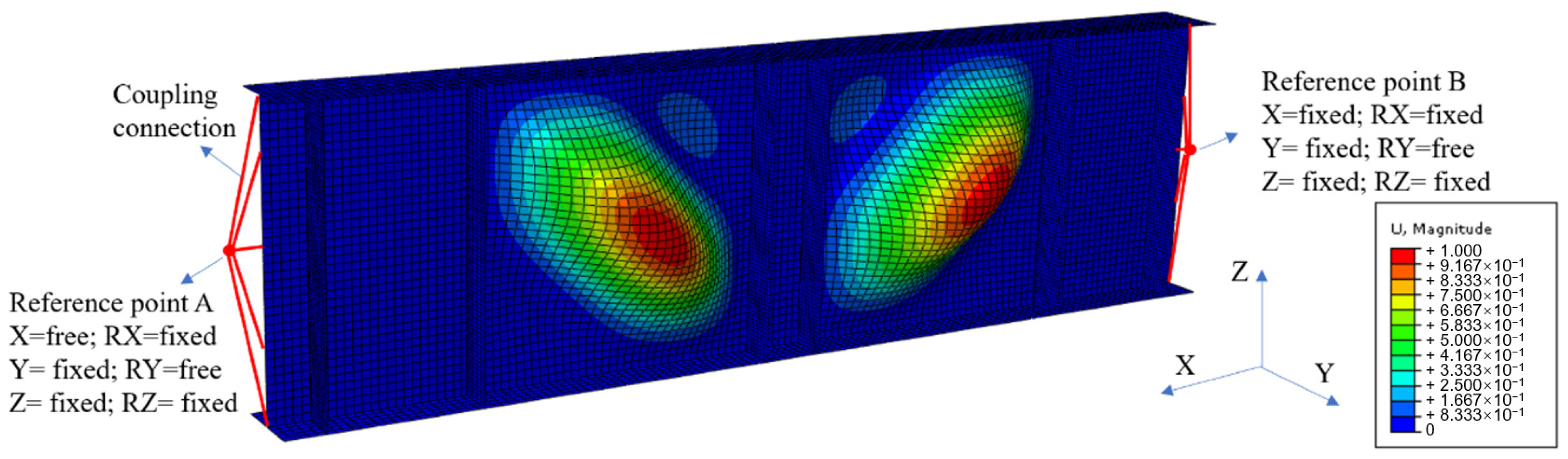
2.2. Numerical Method

The numerical analysis was conducted to investigate the ultimate shear resistance of the S600E sorbite SS plate girder. Similar to the numerical analyses in [7,29,30], the shell element was selected to simulate the plate girder, whose plate thickness was relatively small. The S4R element, whose node contained three rotational and three translational degrees-of-freedom, was used to build the flange, transverse stiffener, and web (Figure 4). A tie connection was used among the flange, transverse stiffener, and web. The simply supported boundary condition was achieved through the reference point and coupling connection. The end sections of the plate girder model were connected with reference points A and B, respectively, where the coupling connection was used. Then, the rotational and translational degrees-of-freedom of the node on the end sections of the plate girder model were the same as those of reference points A and B, respectively. The rotational and translational degrees-of-freedom of reference points A and B are shown in Figure 5. For reference point A, translational degree-of-freedom X and rotational degree-of-freedom RY were free and other rotational and translational degrees-of-freedom were fixed. For reference point B, rotational degree-of-freedom RY was free and other rotational and translational degrees-of-freedom were fixed. A concentrated load was applied on the top flange area between the transverse stiffener, as shown in Figure 4. Out–of–plane constraints were applied on the top flange to protect the plate girder model from lateral–torsional buckling. It is worth noting that the mesh size performed effects on the efficiency and accuracy of the numerical analysis. After a convergence study including different mesh sizes (5 mm, 10 mm, 20 mm, 40 mm, and 80 mm), the 20 mm was selected to be the mesh size for the numerical analysis in this study.
Initial imperfection brought effects on resistant properties of the plate girder, which should be considered in the numerical model. However, the initial imperfection performed significant uncertainty. Hence, a method based on the buckling mode was used to include the effects of initial imperfection, which was widely accepted by many researchers [29,30,31,51,52]. First, the elastic buckling analysis was performed to have the buckling mode of the plate girder. The out-of-plane buckling occurred in web. No clear buckling deformation was observed in the flange and transverse stiffener. The first buckling mode was widely selected to be the initial imperfection form of the plate girders. Then, based on suggestions in the AASHTO Bridge Welding Code [53], hw/100 was selected to be the amplitude of initial imperfection. The keywords of the numerical model in ABAQUS 6.14 software were modified to introduce the initial imperfection. After that, the ultimate resistant analysis on the S600E sorbite SS plate girder could be performed to have the ultimate resistance.

2.3. Numerical Model Validation

For plate girders with a post-buckling capacity, the resistance from the flange was affected by the bending moment. Hence, it is necessary to validate that the FE model was accurate for plate girders under the low-moment high-shear and high-moment high-shear loading conditions. When the bending moment load was lower than the yield bending moment resistance of the flange, it is believed that the effects of the bending moment load on the shear resistance of the web were ignorable, which was considered to be the low-moment high-shear loading condition. When the bending moment load was higher than the yield bending moment resistance of the flange, it is believed that the bending moment load performed adverse effects on the shear resistance of the web, which was considered to be the high-moment high-shear loading condition. The experiment for the stainless steel plate girders under shear loading conducted by Saliba et al. [31] was chosen for the low-moment high-shear loading condition. The I-600 × 200 × 12 × 4-1 specimen with hw/tw = 150 in [31] was also selected to conduct the comparison (Figure 6), which was fabricated with the lean duplex stainless steel. Then, the above comparison stated that the numerical analysis method was appropriate for the stainless steel plate girder under low-moment high-shear loading. For the high-moment high-shear loading, the experimental results in [54] were included. The VM-304-600ad1 specimen with hw/tw = 150 was made with austenitic grade EN 1.4301. A comparison between the experimental and numerical results was shown in Figure 7. Furthermore, a comparison between the failure modes for the experiment and numerical model was conducted, as shown in Figure 8. It is worth noting that for the experimental results, the out-of-plane deformation in one web panel was more obvious than that of another web panel. For the numerical results, the out-of-plane deformation was also observed in both web panels. The numerical results agreed well with the experimental results. The flange local buckling and web tension filed were simulated precisely. Hence, it is clear to see that the numerical analysis method could be used to predict the resistant properties of the stainless steel plate girder under the high-moment high-shear loading accurately. Nevertheless, the above numerical analysis method was used by many researchers [29,30,52,55]. Based on the comprehensive validation, the proposed numerical analysis method could be used to clarify the resistance from flange for the S600E sorbite SS plate girder developing the post-buckling capacity.

2.4. Specimen Dimensions

To investigate the resistance from the flange for the S600E sorbite SS plate girders with post-buckling capacity, the contribution from the web and the flange should be separated from each other, through Vbf,Rd = Vb,RdVbw,Rd. The Vb,Rd denoted the ultimate resistance of the plate girder. The Vbf,Rd and Vbw,Rd denoted the resistance from the flange and web, respectively. Based on the design equations in EN 1993-1-4: 2006+A1 and the study conducted in [29,56], the Vbw,Rd was affected by the dimensions of the web and flange only, when the failure mode was the flange plastic hinge mode. It is believed that when the section dimension of the plate girder was controlled to be the same, the resistance from the web Vbw,Rd remained unchanged. Hence, for the finite element analysis (FEA), the section dimensions of plate girders in the same group were controlled to be the same, which stated that the resistance from the web Vbw,Rd remained unchanged for plate girders in the same group.
For the FEA conducted in this study, the numerical model consisted of the tested panels, the regular panels, the flanges, and the transverse stiffeners, as shown in Figure 9. For the tested panels, they were symmetrically distributed at the mid-span area with the maximum bending moment and shear loading. For the regular panels, they were symmetrically distributed on both sides of the tested panels. The number of the regular panel was controlled to perform the different ratios of the bending moment and shear loading, as shown in Table 2. Then, the different ratios of δ = MEd/Mf,k could be obtained, where Mf,k was the moment of resistance of the cross-section, consisting of the effective area of the flanges only. For all specimens, the thickness of the transverse stiffener was 20 mm. The transverse stiffener was rigid enough to keep the nodal line when the ultimate resistance was exceeded. Consequently, no transverse stiffener buckling failure mode was observed. The flange plastic hinge mode was the only failure mode of specimens, as shown in Figure 10. It can be concluded that the post-buckling capacity of the S600E sorbite SS plate girder was fully developed [29].
In this study, the parametric research for the S600E sorbite SS plate girders with post-buckling capacity was conducted, in which the different flange thicknesses, depth ratios hw/tw, and aspect ratios a/hw were analyzed (see Figure 11). The height of the web was 750 mm. The different depth ratios hw/tw were obtained by changing the thickness of the web. P1-1-150-40 indicated that a/hw =1, hw/tw = 150, and tf = 40 mm. In terms of the development of the post-buckling capacity and engineering practicability, the hw/tw =150/200/250 and aspect ratio a/hw = 1/1.5/2 were designed. The width of the flange was 200 mm. To investigate the resistance from flange and avoid the flange buckling mode, different flange thicknesses were included in the FEA, as shown in Table 3.

2.5. Effect of Strain Hardening

The P1-1-150 plate girder with tf = 30 mm in Table 2 was selected to discuss the effect of strain hardening on the resistance from the flange for the S600E sorbite SS plate girders considering the post-buckling capacity. For the web and the transverse stiffener, the material model included the strain hardening effect. For the flange, the material models with and without the strain hardening effect were used to perform the FEA, separately. For the numerical model without the strain hardening effect, the elastic-perfectly plastic stress–strain curve was used in the flange. For the numerical model with the strain hardening effect, the true stress–strain curve was used in the flange. A comparison between these two FEA results was conducted, as shown in Figure 12. It is clear to see that the material strain hardening in the flange improved the resistance of the S600E sorbite SS plate girders considering the post-buckling capacity, while the flange resistance was not fully used to resist the bending moment. Given that the strain hardening properties of the S600E sorbite SS were different from those of other types of stainless steel, it is significant to study the resistance from the flange for the S600E sorbite SS plate girders considering the effect of strain hardening properties. It should be noted that for all numerical analyses conducted in this study, the strain hardening properties of the S600E sorbite SS were fully considered.

3. Current Design Method

Design methods in EN 1993-1-5 [37] for the carbon steel plate girder and EN 1993-1-4+A1 [32] for the stainless steel plate girder are introduced in this section. It should be noted that the design methods in EN 1993-1-4+A1 [32] were modified from EN 1993-1-5 [37], where the mechanical properties of stainless steel were considered. The design equations in EN 1993-1-5 [37] came from the rotated stress field theory proposed by Höglund [38], which stated the variation trends of compressive stress in the web. Ultimate resistance was determined by Equation (1). The Vbw.Rd and Vbf.Rd were resistance from the web and flange, respectively. Strain hardening properties of stainless steel were considered through the η = 1.20. Vbw.Rd was calculated through Equation (2). It is worth noting that when flange resistance was not completely utilized in resisting the bending moment (MEd < Mf,Rd), the Vbf.Rd could be estimated by Equation (3). For the mild steel plate girder, the c was determined by Equation (4) in Part 1-4 of EN 1993-1-5 [37]. For the stainless steel plate girder, Equation (5) in EN 1993-1-4+A1 [32] was suggested, which was based on the experimental results in [39].
V b , R d = V b w , R d + V b f , R d η f y w A w 3 γ M 1
V b w , R d = χ w f y w A w 3 γ M 1
V b f , R d = b f t f 2 f y f c γ M 1 ( 1 ( M E d M f , R d ) 2 )   M E d < M f , R d
c = a [ 0.25 + 1.6 b f t f 2 f y f t w h w 2 f y w ]
c = a [ 0.17 + 3.5 b f t f 2 f y f t w h w 2 f y w ]   c / a 0.65

4. FEA Results Discussion

4.1. Failure Behavior

The stress–strain properties of the S30408 stainless steel and S600E sorbite SS in Section 2.1 were used in the P1-1-150 numerical model. After the numerical analysis, the failure behavior corresponding to the ultimate resistance of the S600E sorbite SS plate girder was similar with that of the S30408 stainless steel plate girder (see Figure 13). However, the deformation for the S30408 stainless steel plate girder was more obvious than that of the S600E sorbite SS plate girder. Hence, under the same deformation limit, the S600E sorbite SS plate girder could achieve better resistant performance, compared with the S30408 stainless steel plate girder.
In the rotated stress field theory proposed by Höglund [38] which was the theoretical basis for EN 1993–1–5 [37], the c was the distance between plastic hinges, as shown in Figure 14. For the numerical study considering the material and geometrical nonlinearity, the deformation behavior of the S600E sorbite SS plate girder at the post-buckling stage is shown in Figure 15. It is clear to see that there was a certain distribution range of the flange plastic hinge. It is difficult to determine the distance between the plastic hinges accurately based merely on the failure behavior.
After the FEA, the failure behavior of the P1 plate girder in groups of 1-150-35, 1.5-150-35, and 2-150-35 were obtained, as shown in Figure 16. The 1-150-35 denoted that the a/hw = 1, hw/tw =1 50, and tf = 35 mm. The failure mode was the typical flange plastic hinge mode. For the design equations in EN 1993-1-4+A1, Equation (5) was suggested to determine the c for the stainless steel plate girder. However, given Equation (5), the ratio c/a was not affected by a, which was the distance between the transverse stiffeners. As mentioned before, there was a certain distribution range of the flange plastic hinge. It was difficult to determine the distance between the plastic hinges accurately based merely on the failure behavior. However, it is still clear to see that the ratio c/a was affected by the a/hw. Therefore, it might be inappropriate to use the design equation in EN 1993-1-4+A1 to predict the c of S600E sorbite SS plate girders directly. Further verification of the design equation in EN 1993-1-4+A1 is presented in Section 4.3.

4.2. Separation between Vbw,Rd and Vbf,Rd

A new method to determine the c was proposed in this study based on the theoretical basis of EN 1993-1-4+A1 design equations. After the FEA, the resistances for S600E sorbite SS plate girders under the different combined loading were obtained, as shown in Figure 17. The red lines in Figure 17 were guidelines, which were used to determine the condition of Vbf.Rd = 0. The point in Figure 17 were ultimate resistance from numerical results. The 1-150-40 denoted that the a/hw = 1, hw/tw = 150, and tf = 40 mm. It is clear to see that with increases in the MEd/Mf,k, the resistance decreased correspondingly. Considering the theoretical basis of EN 1993-1-4+A1, when MEd = Mf,k, it is believed that Vbf,Rd = 0. Then, the resistance of the plate girder was contributed by Vbw,Rd only. For MEd = Mf,k, a linear interpolation was conducted based on the FEA results. The variable spacing was small, so the results obtained by linear interpolation were considered to be accurate. After that, the Vbf.Rd could be calculated through Vbf.Rd = Vb.RdVbw.Rd. To clarify the above method clearly, the results for the 1.5-150-40 plate girders were processed as an example, as shown in Table 4. Numerical results stated that the turning point was between P9-1.5-150-40 and P10-1.5-150-40. Then, the Vbw,Rd was obtained through linear interpolation. After that, Vbf.Rd was obtained, where the c could be obtained through Equation (3).

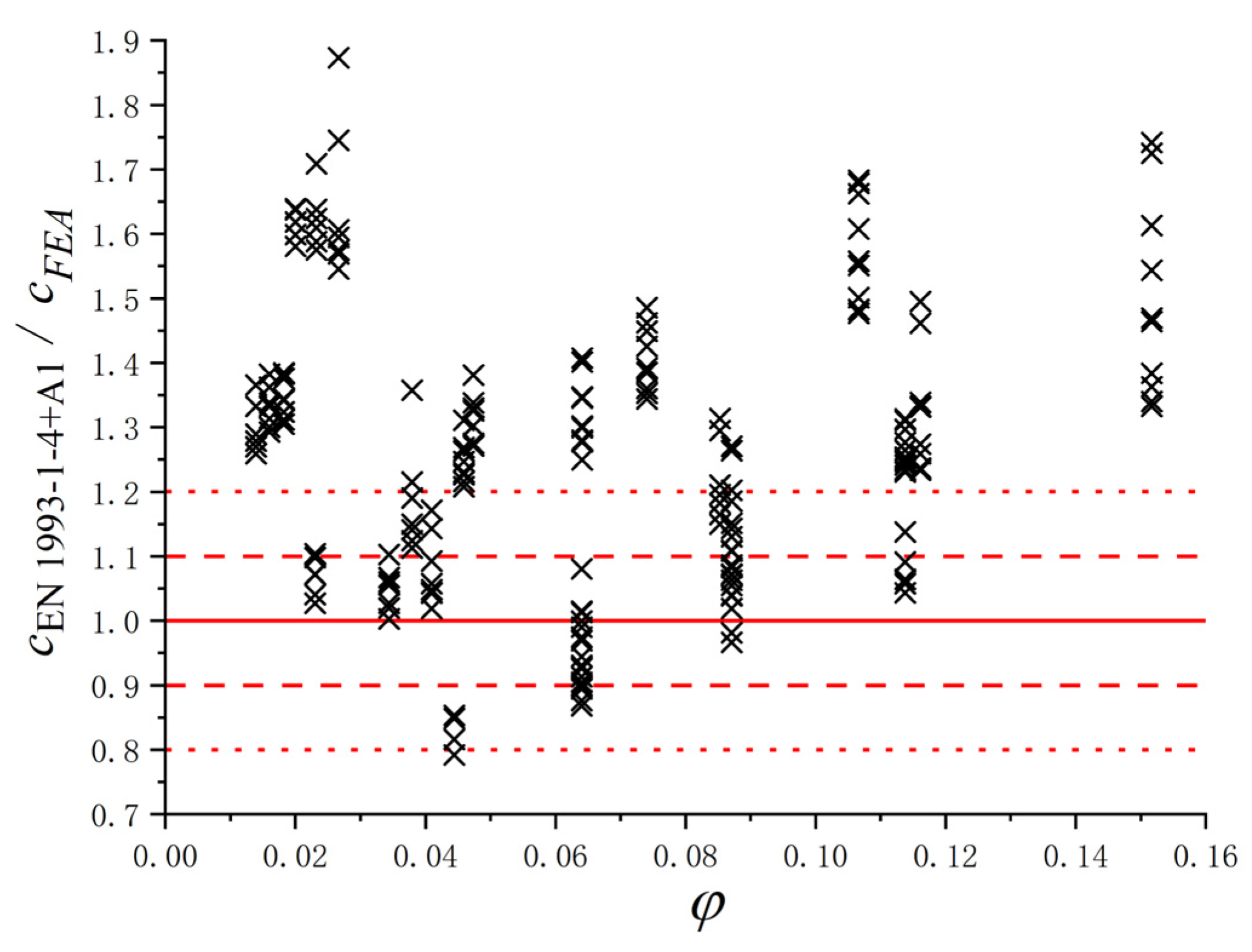
4.3. Verification of EN 1993-1-4+A1 Formula

Based on the parametric study, the results of c for the S600E sorbite SS plate girders with different geometric dimensions were obtained. To verify whether the design equation in EN 1993-1-4+A1 [32] could predict the c accurately, the results of FEA and EN 1993-1-4+A1 design equations were compared (see Figure 18). The red lines in Figure 18 were guidelines, which were used to clarify the difference in c between the numerical results and results from design equation. The points were cEN 1993-1-4+A1/cFEA with different φ. The φ in Figure 18 could be calculated by Equation (6). The results indicated that there were noteworthy errors between the FEA results and the results from Equation (5) in EN 1993-1-4+A1, especially when the φ was relatively large and small. Therefore, the design equation in EN 1993-1-4+A1 [32] could not be directly used to predict the distance between plastic hinges on the flange. Then, considering that the effects of c on the resistance from flange were significant, the Vbf.Rd of the S600E sorbite SS plate girders considering the post-buckling capacity could not be predicted precisely by the EN 1993-1-4+A1 design equations. To investigate the reason for the aforementioned error and propose the appropriate predictive equations, a parameter study was conducted in Section 4.4 and Section 4.5, which considered the hw/tw, a/hw, and MEd/Mf,k.
φ = b f t f 2 f y f / t w h w 2 f y w

4.4. Influence of the Depth Ratio hw/tw and Aspect Ratio a/hw

The original equation proposed by Höglund [38], Equation (4), was selected in this study to investigate the influence of the hw/tw. The results of FEA and Equation (4) were compared (see Figure 19). It is easy to see that the hw/tw had influenced the cFEA/cEq. (4). With increases in the hw/tw, the cFEA/cEq. (4) decreased correspondingly. A similar comparison was conducted to investigate the influence of the a/hw, as shown in Figure 20. It turns out that the effect of the a/hw on the cFEA/cEq. (4) could not be ignored. Therefore, to predict the c accurately, the influence of the hw/tw and a/hw should be considered. It is worth noting that the above values of cFEA were obtained through the method in Section 4.2.

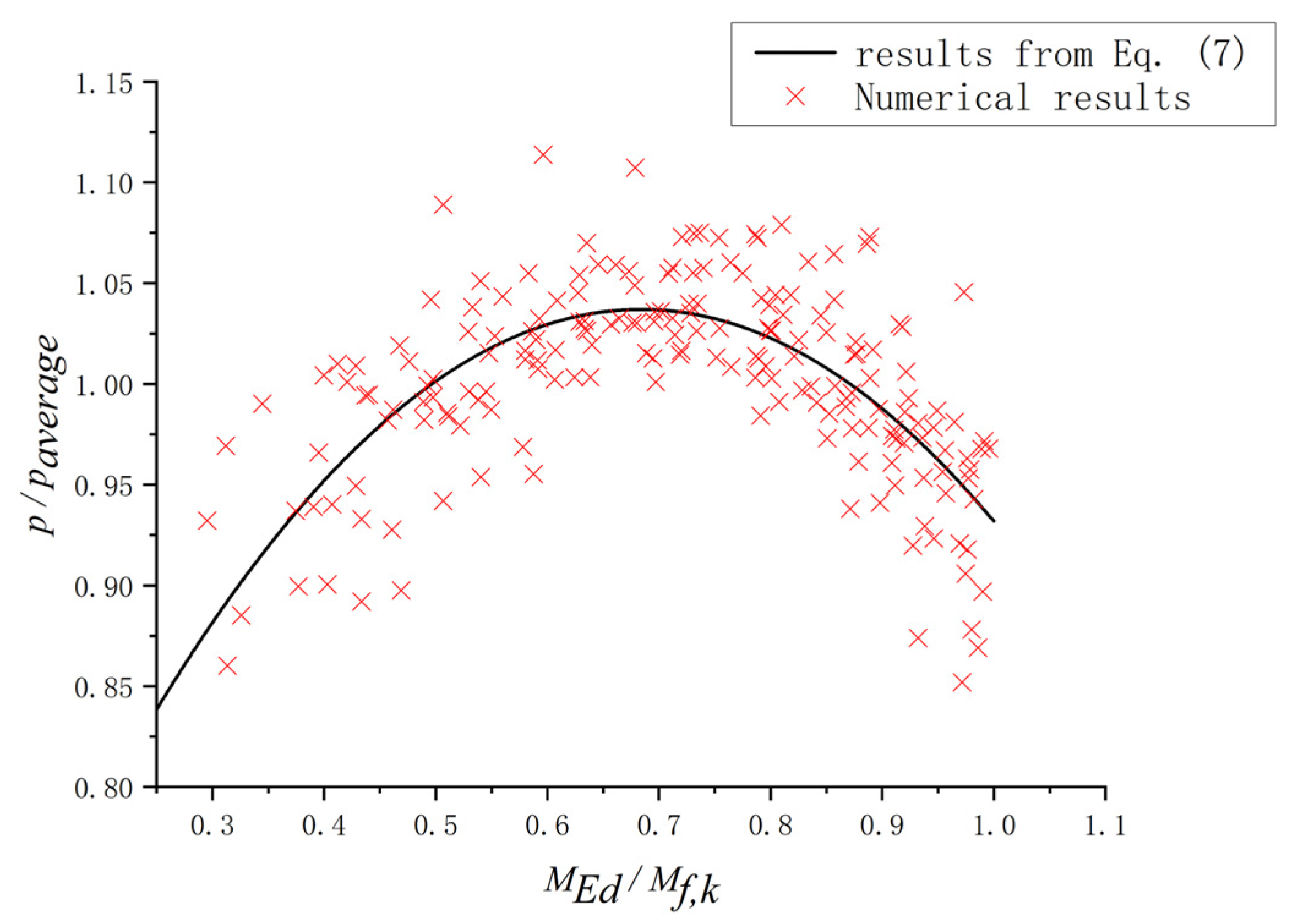
4.5. Influence of Ratio MEd/Mf,k

After the numerical analysis, it turned out that for the plate girders with the same section dimensions, the c changed with different bending moments and shear loadings. However, for EN 1993-1-4+A1 [32], the c was not influenced by the γ = MEd/Mf,k, as shown in Equation (5). The influence of the γ on the c should be included to predict the c more accurately. To study the effect of the γ on the p = c/a, α = p/paverage was selected to perform a non-dimensional treatment, where paverage was the mean value of the p for the plate girders in the same group. For the plate girders in the same group, the hw/tw, a/hw, and tf remained unchanged. Based on the parametric study conducted in this paper, the ratios p/paverage for plate girders with different ratios MEd/Mf,k are shown in Figure 21. The results indicated that there was a relationship between the α and γ. Then, a numerical fitting was performed to clarify the aforementioned relationship between the α and γ. Equation (7) was proposed to quantify the influence of the MEd/Mf,k.
α = 1.054 γ 2 + 1.442 γ + 0.544

5. Modification for Design Equation in EN 1993-1-4+A1

To predict the resistance from the flange accurately, the design equation in EN 1993-1-4+A1 for the c needed to be modified. Considering that the design equations in EN 1993-1-5 [37] and EN 1993-1-4+A1 [32] were all based on the rotated stress field theory proposed by Höglund [38], a new correction factor ρ for the original Equation (4) proposed by Höglund [38] was suggested in this study, as shown in Equation (8). Based on the parametric study conducted in this paper, the values of the c for the S600E sorbite SS plate girders with different hw/tw, a/hw, tf, and MEd/Mf,k were obtained. After the numerical fitting, the correction factor ρ could be estimated utilizing Equation (9), which included the influence of the hw/tw, a/hw, and MEd/Mf,k. It is worth noting that the effects of MEd/Mf,k could be reflected by α. To verify the accuracy, the FEA results, the results from Equation (5) in EN 1993-1-4+A1, and the new modified Equation (8) were compared, as shown in Figure 22. It could be found that the error associated with Equation (8) was basically controlled within 10%, which was obviously smaller than that of Equation (5). For Equation (8), the average ratio cEq. (8)/cFEA = 1.001 and the coefficient of variance Cv,Eq. (8) = 0.055. For Equation (5) in EN 1993-1-4+A1, cEq. (5)/cFEA = 1.262 and Cv,Eq. (5) = 0.217. Consequently, the new modified Equation (8) could predict the resistance from the flange more accurately.
c = a ( 0.25 + 1.6 b f t f 2 f y f t w h w 2 f y w ) ρ
ρ = ( 1.333 + 0.3465 a h w 0.0009074 h w t w 0.002583 a t w ) α

6. Conclusions

In the study, the S600E sorbite SS was introduced in the plate girder to increase its resistant properties and durability. The resistance from the flange of the S600E sorbite SS plate girders developing the post-buckling capacity was studied based on a numerical analysis. The main conclusions are as follows:
1. It is difficult to determine the distance between the plastic hinges accurately based merely on the failure behavior. Therefore, considering the theoretical basis of EN 1993-1-4+A1, a new method to determine the c was proposed to avoid the aforementioned error.
2. The failure behavior for the S600E sorbite SS plate girders with different a/hw was obtained. It indicated that with differences in the a/hw, the c/a changed correspondingly. The aforementioned influence was not included in the design equations in EN 1993-1-4+A1.
3. The results showed that the error between the numerical analysis and the EN 1993-1-4+A1 design equation should not be ignored. The design equation in EN 1993-1-4+A1 could not be directly selected to predict the resistance from the flange for the S600E sorbite SS plate girders with post-buckling capacity.
4. Based on the parametric study, the results indicated that the hw/tw, a/hw, and MEd/Mf,k had effects on the value of the c. After the numerical fitting, the correction factor ρ was proposed, which included the influence of the hw/tw, a/hw, and MEd/Mf,k.
Considering the advantage of the S600E sorbite SS, it could be widely used in structures in corrosive environments. The transverse patch loading was commonly applied on the plate girder, such as wheel load. The resistant properties of the S600E sorbite SS plate girder under patch loading should be investigated.

Author Contributions

Data curation, N.W. and J.L.; Investigation, X.X., N.W. and F.W.; Methodology, X.X., L.H. (Lepeng Huang) and Z.C.; Project administration, L.H. (Lepeng Huang); Software, L.H. (Letian Hai); Supervision, J.H.; Validation, J.H. and F.W.; Writing—original draft, X.X.; Writing—review & editing, L.H. (Lepeng Huang). All authors have read and agreed to the published version of the manuscript.

Funding

This research was funded by the National Natural Science Foundation of China (52108115).

Institutional Review Board Statement

Not applicable.

Acknowledgments

The authors wish to acknowledge the support of the National Natural Science Foundation of China (52108115).

Conflicts of Interest

The authors declare no conflict of interest.

References

  1. Baddoo, N.R. Stainless steel in construction: A review of research, applications, challenges and opportunities. J. Constr. Steel Res. 2008, 64, 1199–1206. [Google Scholar] [CrossRef]
  2. Estrada, I.; Real, E.; Mirambell, E. General behaviour and effect of rigid and non-rigid end post in stainless steel plate girders loaded in shear. Part I: Experimental study. J. Constr. Steel Res. 2007, 63, 970–984. [Google Scholar] [CrossRef]
  3. Liu, G.; Hua, J.; Wang, N.; Deng, W.; Xue, X. Material Alternatives for Concrete Structures on Remote Islands: Based on Life-Cycle-Cost Analysis. Adv. Civ. Eng. 2022, 2022, 7329408. [Google Scholar] [CrossRef]
  4. Wang, F.; Hua, J.; Xue, X.; Ding, Z.; Lyu, Y.; Liu, Q. Low-cycle fatigue performance of bimetallic steel bar considering the effect of inelastic buckling. Constr. Build. Mater. 2022, 351, 128787. [Google Scholar] [CrossRef]
  5. Hua, J.; Wang, F.; Xue, X.; Ding, Z.; Chen, Z. Residual monotonic mechanical properties of bimetallic steel bar with fatigue damage. J. Build. Eng. 2022, 55, 104703. [Google Scholar] [CrossRef]
  6. Hua, J.; Yang, Z.; Wang, F.; Xue, X.; Wang, N.; Huang, L. Relation between the Metallographic Structure and Mechanical Properties of a Bimetallic Steel Bar after Fire. J. Mater. Civ. Eng. 2022, 34, 04022193. [Google Scholar] [CrossRef]
  7. Hua, J.; Xue, X.; Huang, Q.; Shi, Y.; Deng, W. Post-fire performance of high-strength steel plate girders developing post-buckling capacity. J. Build. Eng. 2022, 52, 104442. [Google Scholar] [CrossRef]
  8. Shi, Y.; Luo, Z.; Zhou, X.; Xue, X.; Xiang, Y. Post-fire performance of bonding interface in explosion-welded stainless-clad bimetallic steel. J. Constr. Steel Res. 2022, 193, 107285. [Google Scholar] [CrossRef]
  9. Shi, Y.; Luo, Z.; Zhou, X.; Xue, X.; Li, J. Post-fire mechanical properties of titanium–clad bimetallic steel in different cooling approaches. J. Constr. Steel Res. 2022, 191, 107169. [Google Scholar] [CrossRef]
  10. Wang, F.; Hua, J.; Xue, X.; Wang, N.; Yao, Y. Effects of Polyoxymethylene Fiber on Mechanical Properties of Seawater Sea-Sand Concrete with Different Ages. Polymers 2022, 14, 3472. [Google Scholar] [CrossRef]
  11. Hua, J.; Yang, Z.; Xue, X.; Huang, L.; Wang, N.; Chen, Z. Bond properties of bimetallic steel bar in seawater sea-sand concrete at different ages. Constr. Build. Mater. 2022, 323, 126539. [Google Scholar] [CrossRef]
  12. Su, A.; Sun, Y.; Liang, Y.; Zhao, O. Material properties and membrane residual stresses of S690 high strength steel welded I-sections after exposure to elevated temperatures. Thin-Walled Struct. 2020, 152, 106723. [Google Scholar] [CrossRef]
  13. Arrayago, I.; Real, E.; Gardner, L. Description of stress–strain curves for stainless steel alloys. Mater. Des. 2015, 87, 540–552. [Google Scholar] [CrossRef]
  14. Zhou, F.; Young, B. Cold-Formed High-Strength Stainless Steel Tubular Sections Subjected to Web Crippling. J. Struct. Eng. 2007, 133, 368–377. [Google Scholar] [CrossRef]
  15. Zhou, F.; Li, L. Experimental study on hysteretic behavior of structural stainless steels under cyclic loading. J. Constr. Steel Res. 2016, 122, 94–109. [Google Scholar] [CrossRef]
  16. Zhou, F.; Chen, Y.; Young, B. Cold-formed high strength stainless steel cross-sections in compression considering interaction effects of constituent plate elements. J. Constr. Steel Res. 2013, 80, 32–41. [Google Scholar] [CrossRef]
  17. Hai, L.; Ban, H. Full-range stress-strain relation of stainless-clad bimetallic steel: Constitutive modelling. J. Build. Eng. 2022, 57, 104868. [Google Scholar] [CrossRef]
  18. Hua, J.; Wang, F.; Xiang, Y.; Yang, Z.; Xue, X.; Huang, L.; Wang, N. Mechanical properties of stainless-clad bimetallic steel bars exposed to elevated temperatures. Fire Saf. J. 2022, 127, 103521. [Google Scholar] [CrossRef]
  19. Hua, J.; Fan, H.; Yan, W.; Wang, N.; Xue, X.; Huang, L. Seismic resistance of the corroded bimetallic steel bar under different strain amplitudes. Constr. Build. Mater. 2022, 319, 126088. [Google Scholar] [CrossRef]
  20. Hua, J.; Wang, F.; Yang, Z.; Xue, X.; Huang, L.; Chen, Z. Low-cycle fatigue properties of bimetallic steel bars after exposure to elevated temperature. J. Constr. Steel Res. 2021, 187, 106959. [Google Scholar] [CrossRef]
  21. Hua, J.; Fan, H.; Xue, X.; Wang, F.; Chen, Z.; Huang, L.; Wang, N. Tensile and low-cycle fatigue performance of bimetallic steel bars with corrosion. J. Build. Eng. 2021, 43, 103188. [Google Scholar] [CrossRef]
  22. Hua, J.; Wang, F.; Huang, L.; Wang, N.; Xue, X. Experimental study on mechanical properties of corroded stainless-clad bimetallic steel bars. Constr. Build. Mater. 2021, 287, 123019. [Google Scholar] [CrossRef]
  23. Zhou, F.; Huang, L.; Li, H.-T. Cold-formed stainless steel SHS and RHS columns subjected to local-flexural interactive buckling. J. Constr. Steel Res. 2021, 188, 106999. [Google Scholar] [CrossRef]
  24. Zhou, F.; Long, G. Element interaction of cold-formed stainless steel cross-sections subjected to major axis bending. J. Constr. Steel Res. 2016, 118, 22–40. [Google Scholar] [CrossRef]
  25. Zhou, F.; Young, B. Web crippling behaviour of cold-formed duplex stainless steel tubular sections at elevated temperatures. Eng. Struct. 2013, 57, 51–62. [Google Scholar] [CrossRef] [Green Version]
  26. Zhou, F.; Ling, Y.; Huang, P. Tests of carbon fibre–reinforced polymer strengthened cold-formed stainless steel tubular sections subjected to web crippling. Adv. Struct. Eng. 2016, 19, 1755–1768. [Google Scholar] [CrossRef]
  27. Zheng, B.; Yang, S.; Jin, X.; Shu, G.; Dong, S.; Jiang, Q. Test on residual stress distribution of welded S600E high-strength stainless steel sections. J. Constr. Steel Res. 2020, 168, 105994. [Google Scholar] [CrossRef]
  28. Xue, X.Y.; Zhou, X.; Shi, Y.; Xiang, Y. Ultimate shear resistance of S600E high-strength stainless steel plate girders. J. Constr. Steel Res. 2021, 179, 106535. [Google Scholar] [CrossRef]
  29. Xiao, Y.; Xue, X.Y.; Sun, F.F.; Li, G.Q. Postbuckling shear capacity of high-strength steel plate girders. J. Constr. Steel Res. 2018, 150, 475–490. [Google Scholar] [CrossRef]
  30. Xiao, Y.; Xue, X.Y.; Sun, F.F.; Li, G.Q. Intermediate transverse stiffener requirements of high-strength steel plate girders considering postbuckling capacity. Eng. Struct. 2019, 196, 109289. [Google Scholar] [CrossRef]
  31. Saliba, N.; Gardner, L. Experimental study of the shear response of lean duplex stainless steel plate girders. Eng. Struct. 2013, 46, 375–391. [Google Scholar] [CrossRef]
  32. EN 1993–1–4: 2006+A1; Eurocode 3: Design of Steel Structures–Part 1.4: General Rules–Supplementary Rules for Stainless Steels. European Committee for Standardization: Brussels, Belgium, 2015.
  33. Kwon, Y.B.; Ryu, S.W. The shear strength of end web panels of plate girders with tension field action. Thin-Walled Struct. 2016, 98, 578–591. [Google Scholar] [CrossRef]
  34. Basler, K. Strength of plate girders in shear. J. Struct. Div. 1961, 128, 151–180. [Google Scholar] [CrossRef]
  35. Wilson, J.M. On Specifications for Strength of Iron Bridges. Trans. Am. Soc. Civ. Eng. 1886, 15, 389–414. [Google Scholar] [CrossRef]
  36. Zhou, F.; Young, B.; Lam, H.-C. Welded aluminum alloy plate girders subjected to shear force. J. Adv. Steel Constr. 2012, 8, 71–94. [Google Scholar] [CrossRef]
  37. EN 1993–1–5; Eurocode 3: Design of Steel Structures–Part 1.5: Plated Structural Elements. European Committee for Standardization: Brussels, Belgium, 2010.
  38. Höglund, T. Shear buckling resistance of steel and aluminium plate girders. Thin-Walled Struct. 1997, 29, 13–30. [Google Scholar] [CrossRef]
  39. Olsson, A. Stainless Steel Plasticity–Material Modelling and Structural Applications; Luleå University of Technology: Luleå, Sweden, 2001. [Google Scholar]
  40. Saliba, N.; Real, E.; Gardner, L. Shear design recommendations for stainless steel plate girders. Eng. Struct. 2014, 59, 220–228. [Google Scholar] [CrossRef]
  41. Mansour, W.; Sakr, M.A.; Seleemah, A.A.; Tayeh, B.A.; Khalifa, T.M. Bond behavior between concrete and prefabricated Ultra High-Performance Fiber-Reinforced Concrete (UHPFRC) plates. Struct. Eng. Mech. 2022, 81, 305–316. [Google Scholar] [CrossRef]
  42. Mansour, W. Numerical analysis of the shear behavior of FRP-strengthened continuous RC beams having web openings. Eng. Struct. 2020, 227, 111451. [Google Scholar] [CrossRef]
  43. Baraghith, A.T.; Mansour, W.; Behiry, R.N.; Fayed, S. Effectiveness of SHCC strips reinforced with glass fiber textile mesh layers for shear strengthening of RC beams: Experimental and numerical assessments. Constr. Build. Mater. 2022, 327, 127036. [Google Scholar] [CrossRef]
  44. Hamoda, A.; Emara, M.; Mansour, W. Behavior of steel I-beam embedded in normal and steel fiber reinforced concrete incorporating demountable bolted connectors. Compos. Part B Eng. 2019, 174, 106996. [Google Scholar] [CrossRef]
  45. Mansour, W.; Tayeh, B.A.; Tam, L.-H. Finite element analysis of shear performance of UHPFRC-encased steel composite beams: Parametric study. Eng. Struct. 2022, 271, 114940. [Google Scholar] [CrossRef]
  46. Hua, J.; Wang, F.; Xue, X. Study on fatigue properties of post-fire bimetallic steel bar with different cooling methods. Structures 2022, 40, 633–645. [Google Scholar] [CrossRef]
  47. Hua, J.; Wang, F.; Xue, X.; Fan, H.; Yan, W. Fatigue properties of bimetallic steel bar: An experimental and numerical study. Eng. Fail. Anal. 2022, 136, 106212. [Google Scholar] [CrossRef]
  48. Hua, J.; Wang, F.; Xue, X.; Ding, Z.; Sun, Y.; Xiao, L. Ultra-low cycle fatigue performance of Q690 high-strength steel after exposure to elevated temperatures. J. Build. Eng. 2022, 57, 104832. [Google Scholar] [CrossRef]
  49. Zhou, X.; Xue, X.; Shi, Y.; Xu, J. Post-fire mechanical properties of Q620 high-strength steel with different cooling methods. J. Constr. Steel Res. 2021, 180, 106608. [Google Scholar] [CrossRef]
  50. Hua, J.; Yang, Z.; Zhou, F.; Hai, L.; Wang, N.; Wang, F. Effects of exposure temperature on low–cycle fatigue properties of Q690 high–strength steel. J. Constr. Steel Res. 2022, 190, 107159. [Google Scholar] [CrossRef]
  51. Hassanein, M. Imperfection analysis of austenitic stainless steel plate girders failing by shear. Eng. Struct. 2010, 32, 704–713. [Google Scholar] [CrossRef]
  52. Choi, Y.S.; Kim, D.; Lee, S.C. Ultimate shear behavior of web panels of HSB800 plate girders. Constr. Build. Mater. 2015, 101, 828–837. [Google Scholar] [CrossRef]
  53. AASHTO/AWS, ANSI/AASHTO/AWS D1.5M/D1.5:2002; Bridge Welding Code. American Association of State Highway and Transportation Officials, Inc.: Washington, DC, USA; American Welding Society: Miami, FL, USA, 2002.
  54. Chen, X.; Yuan, H.; Real, E.; Du, X.; Schafer, B. Experimental behaviour of stainless steel plate girders under combined bending and shear. J. Constr. Steel Res. 2019, 166, 105900. [Google Scholar] [CrossRef]
  55. Dos Santos, G.; Gardner, L. Design recommendations for stainless steel I-sections under concentrated transverse loading. Eng. Struct. 2019, 204, 109810. [Google Scholar] [CrossRef]
  56. Xiao, L.; Hua, J.; Li, H.; Xue, X.; Wang, N.; Wang, F. Quantitative analysis on post–fire–resistant performance of high–strength steel plate girders using LSTM. J. Constr. Steel Res. 2022, 199, 107588. [Google Scholar] [CrossRef]
Figure 1. Corrosion in structural and reinforcing steels. (a) structural steel; (b) reinforcing steel.
Materials 15 08069 g001
Figure 2. Plate girder engineering application.
Materials 15 08069 g002
Figure 3. Comparison in stress–strain curves between stainless steel and carbon steel [27,29].
Materials 15 08069 g003
Figure 4. Structural form of plate girder model.
Materials 15 08069 g004
Figure 5. First buckling mode of the S600E sorbite SS plate girder.
Materials 15 08069 g005
Figure 6. Comparison between experimental [31] and numerical results for plate girder under low-moment high-shear loading.
Materials 15 08069 g006
Figure 7. Comparison between experimental [54] and numerical results for the plate girder under high-moment high-shear loading.
Materials 15 08069 g007
Figure 8. Failure behaviors comparison: (a) experiment specimen [54]; (b) FE model in this study.
Materials 15 08069 g008aMaterials 15 08069 g008b
Figure 9. Structure form of plate girder model.
Materials 15 08069 g009
Figure 10. Failure modes of S600E sorbite SS plate girders: (a) P1-1-150-40; (b) P11-1-150-40.
Materials 15 08069 g010
Figure 11. Schematic representation of numerical parameter study.
Materials 15 08069 g011
Figure 12. Effect of strain hardening on the resistance.
Materials 15 08069 g012
Figure 13. Failure behavior of the S30408 and S600E stainless steel plate girders.
Materials 15 08069 g013
Figure 14. Tension field mechanism for post-buckling stage.
Materials 15 08069 g014
Figure 15. Distribution range of flange plastic hinges.
Materials 15 08069 g015
Figure 16. Failure behaviors of the P1 plate girders for 1-150-35, 1.5-150-35, and 2-150-35.
Materials 15 08069 g016
Figure 17. FEA results of S600E sorbite SS plate girders under the different bending moments and shear loadings.
Materials 15 08069 g017
Figure 18. Comparison between the results from numerical analysis and the EN 1993-1-4+A1 design equations for S600E sorbite SS plate girders with post-buckling capacity.
Materials 15 08069 g018
Figure 19. Influence of the hw/tw on the cFEA/cEq. (4).
Materials 15 08069 g019
Figure 20. Influence of the a/hw on the cFEA/cEq. (4).
Materials 15 08069 g020
Figure 21. Comparison between numerical results and results from Equation (7).
Materials 15 08069 g021
Figure 22. Comparison between the results from FEA, the EN 1993-1-4+A1 design equation for stainless steel plate girders, and the new modified Equation (8).
Materials 15 08069 g022
Table 1. Chemical composition of different structural steels (wt. %).
TypeCSiMnPSCrNiAltMoTiCuNbV
S600E sorbite stainless steel0.090.470.790.0770.00413.431.46
S30408 austenitic stainless steel≤0.08≤0.75≤2.0≤0.045≤0.0318–208–10.5
Q235 mild steel0.160.140.530.0310.0260.0140.014
Q690 high-strength steel0.1480.271.230.0160.0040.170.010.380.1290.0170.010.020.001
Table 2. Geometric dimensions for S600E sorbite SS plate girders: a/hw = 1, hw/tw = 150.
NumberL/mmhw/mmbf/mma/hwN × e/mmts/mm
P1-1-150185075020010 × 37520
P2-1-150260075020012 × 37520
P3-1-150335075020014 × 37520
P4-1-150410075020016 × 37520
P5-1-150485075020018 × 37520
P6-1-1505600750200110 × 37520
P7-1-1506350750200112 × 37520
P8-1-1507100750200114 × 37520
P9-1-1507850750200116 × 37520
P10-1-1508600750200118 × 37520
P11-1-1509350750200120 × 37520
Table 3. Different tf for S600E sorbite SS plate girders.
Number tf/mm
P1-1-150~P11-1-15030/35/40
P1-1.5-150~P10-1.5-15030/35/40
P1-2-150~P9-2-15025/30/35
P1-1-200~P11-1-20030/35/40
P1-1.5-200~P10-1.5-20022/24/26
P1-2-200~P9-2-20018/20/22
P1-1-250~P11-1-25020/25/30
P1-1.5-250~P10-1.5-25014/15/16
P1-2-250~P9-2-25013/14/15
Table 4. Numerical results for S600E sorbite SS plate girders: 1.5-150-40.
NumberVb.Rd/kNMEd/Mf,kVbf.Rd/kNcFEA/mmcEq. (5)/mm
P1-1.5-150-401114.51 0.395 303.10 486.90 639.25
P2-1.5-150-401074.25 0.498 262.84 500.67 639.25
P3-1.5-150-401034.43 0.591 223.02 509.91 639.25
P4-1.5-150-40994.15 0.676 182.74 519.29 639.25
P5-1.5-150-40956.73 0.755 145.32 517.98 639.25
P6-1.5-150-40919.68 0.825 108.26 515.00 639.25
P7-1.5-150-40883.86 0.889 72.45 505.46 639.25
P8-1.5-150-40848.72 0.946 37.31 493.06 639.25
P9-1.5-150-40814.29 0.996 2.88 487.83 639.25
P10-1.5-150-40781.90 1.041 ---
Publisher’s Note: MDPI stays neutral with regard to jurisdictional claims in published maps and institutional affiliations.

