
The Influence of Graded Amount of Potassium Permanganate on Corrosion of Hot-Dip Galvanized Steel in Simulated Concrete Pore Solutions
 , , , and
Abstract
:1. Introduction
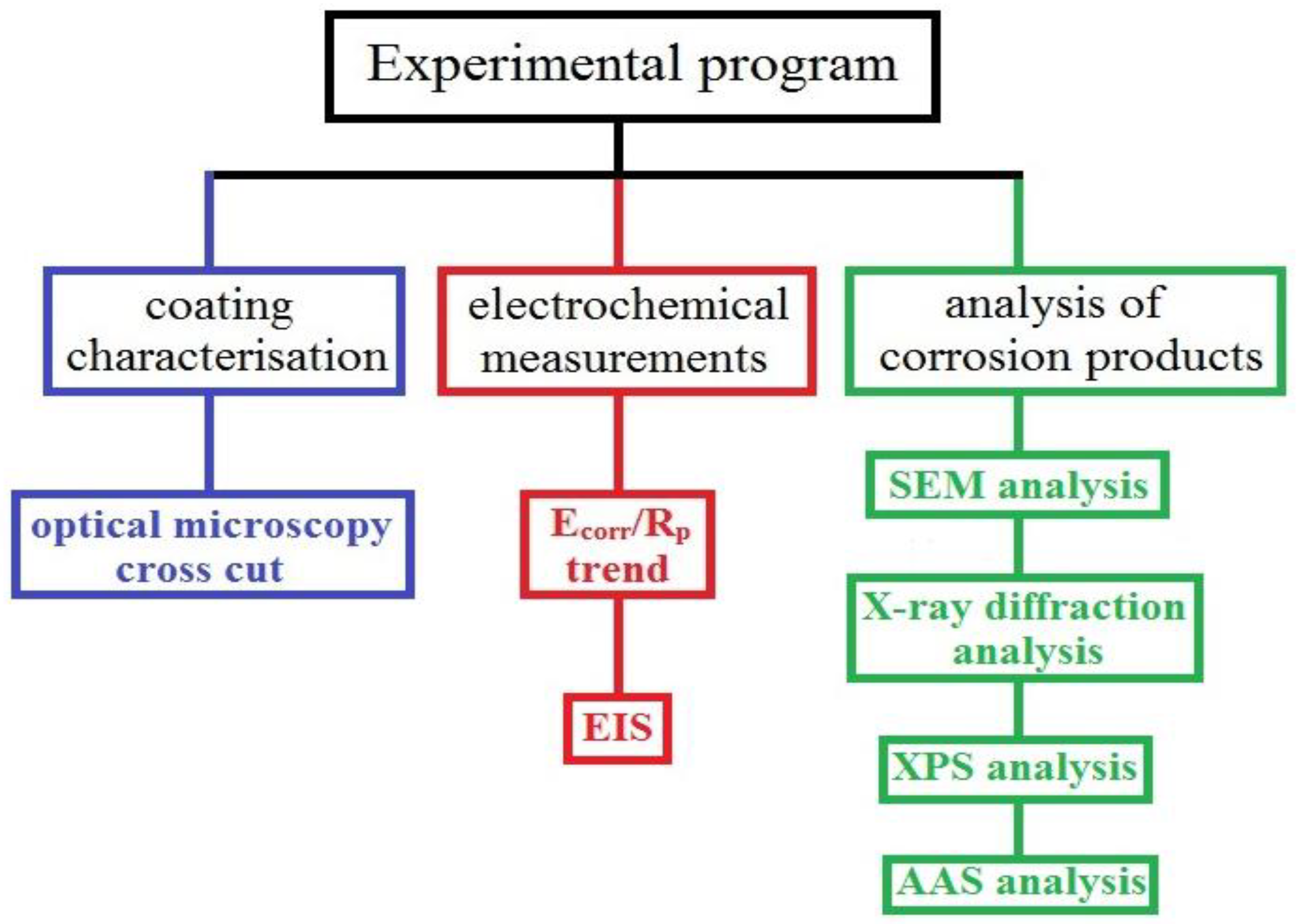
2. Materials and Methods
3. Results and Discussion
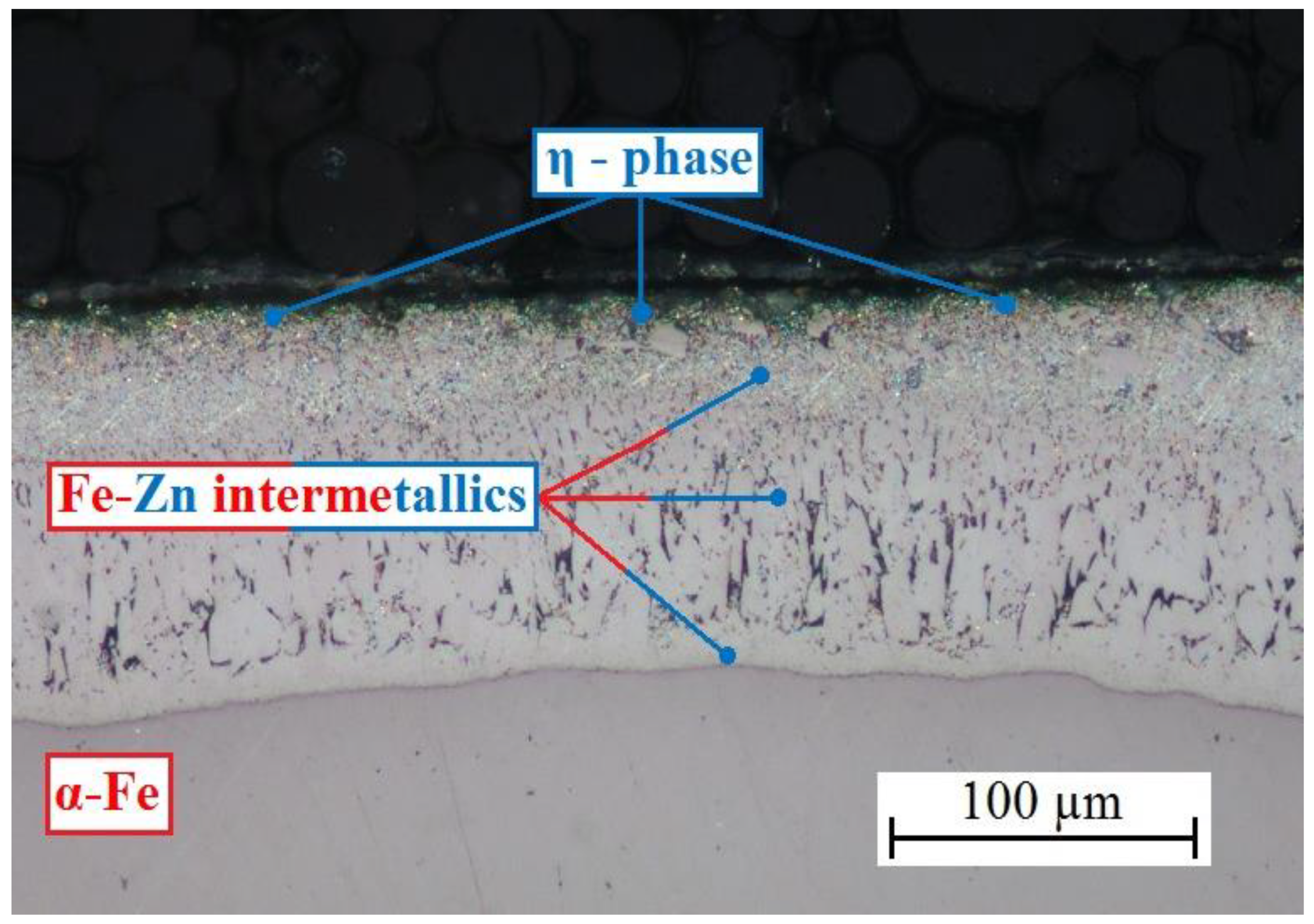
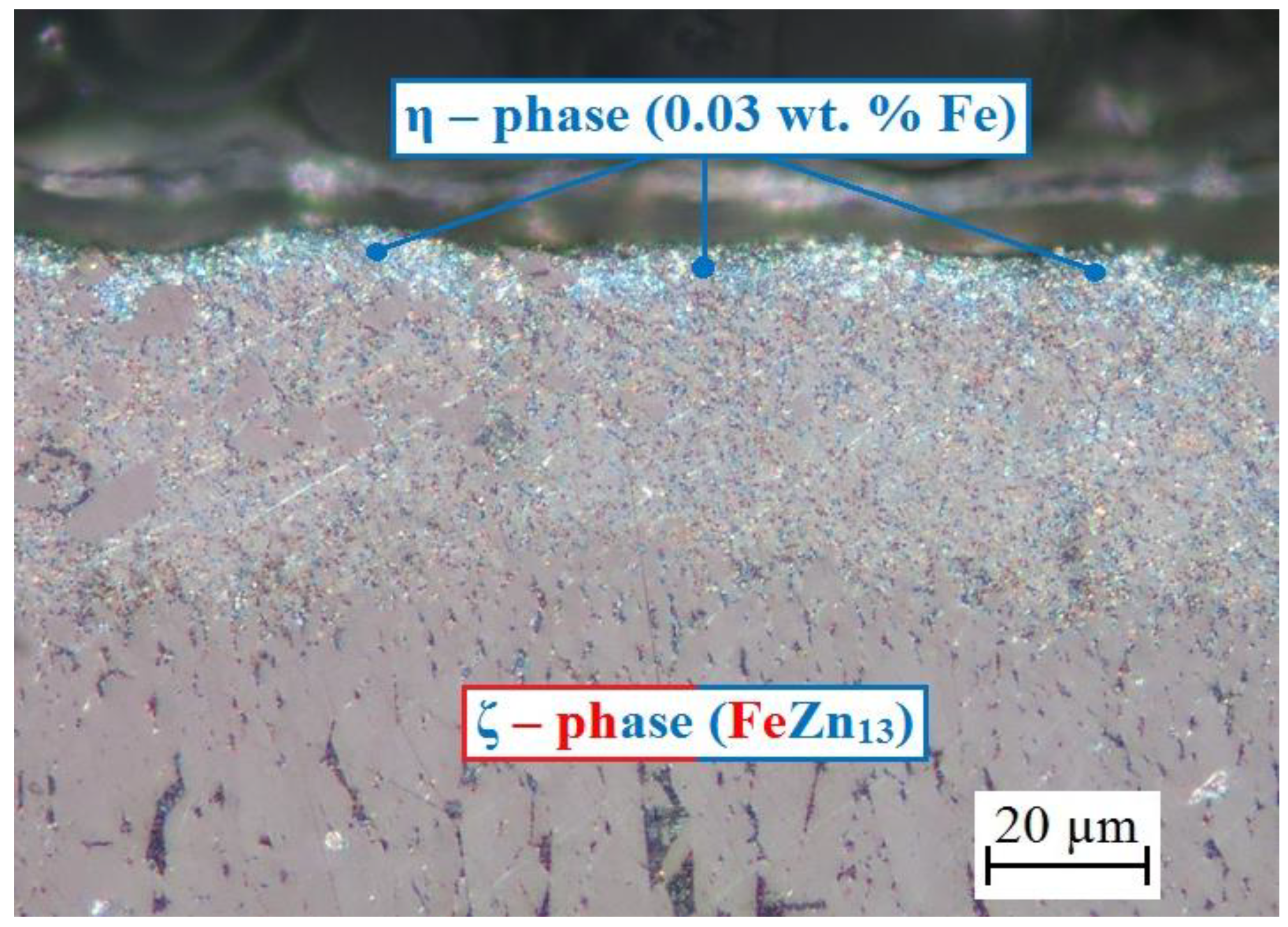
3.1. Structure of HDG Coating
3.2. Electrochemical Measurements
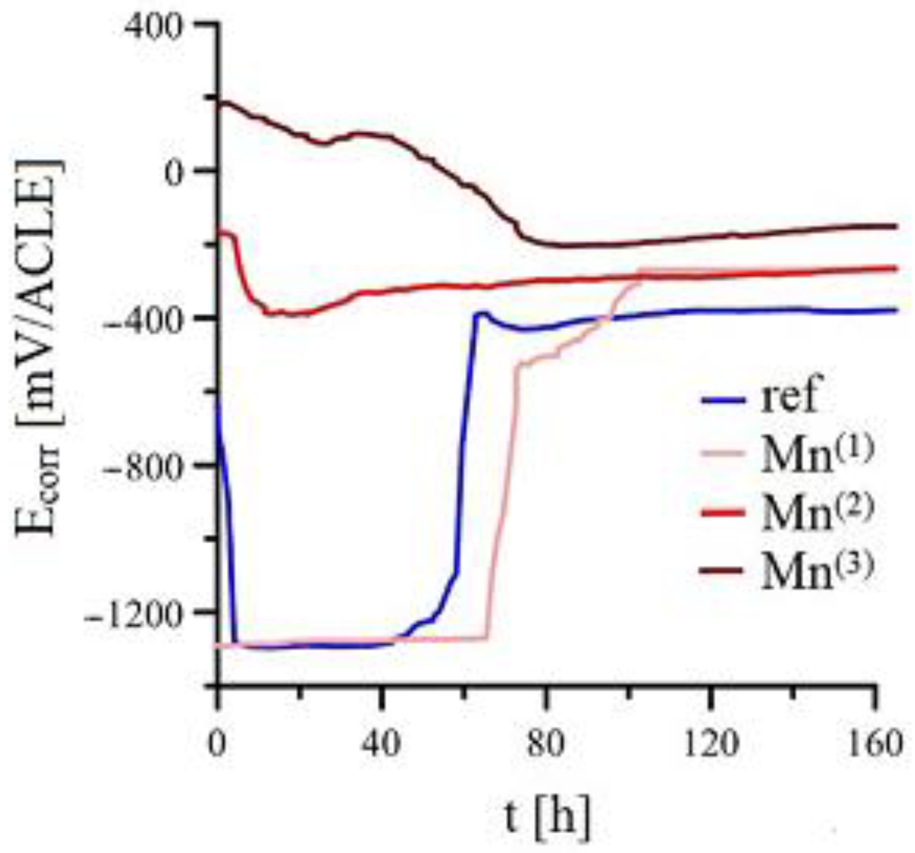
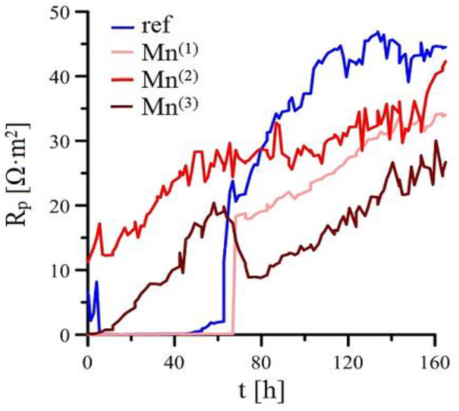
3.2.1. Ecorr/Rp Trend
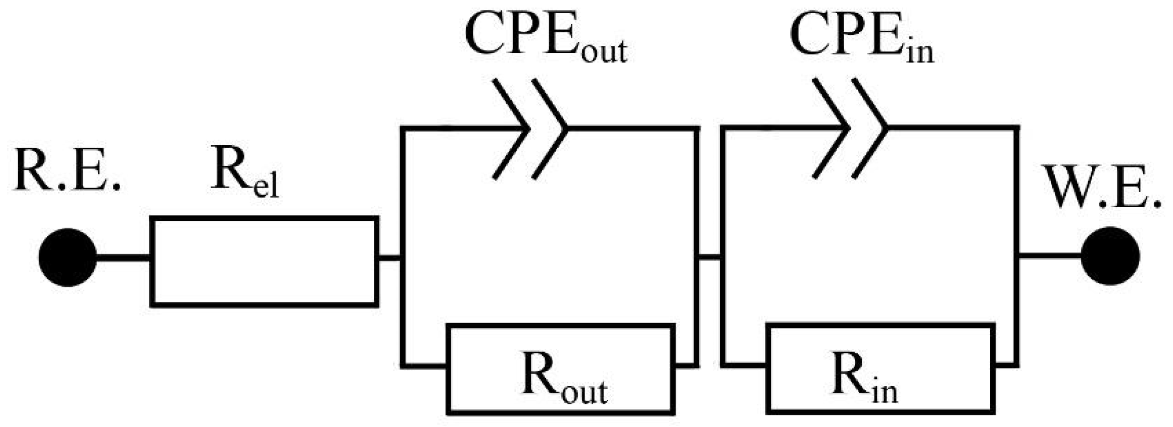
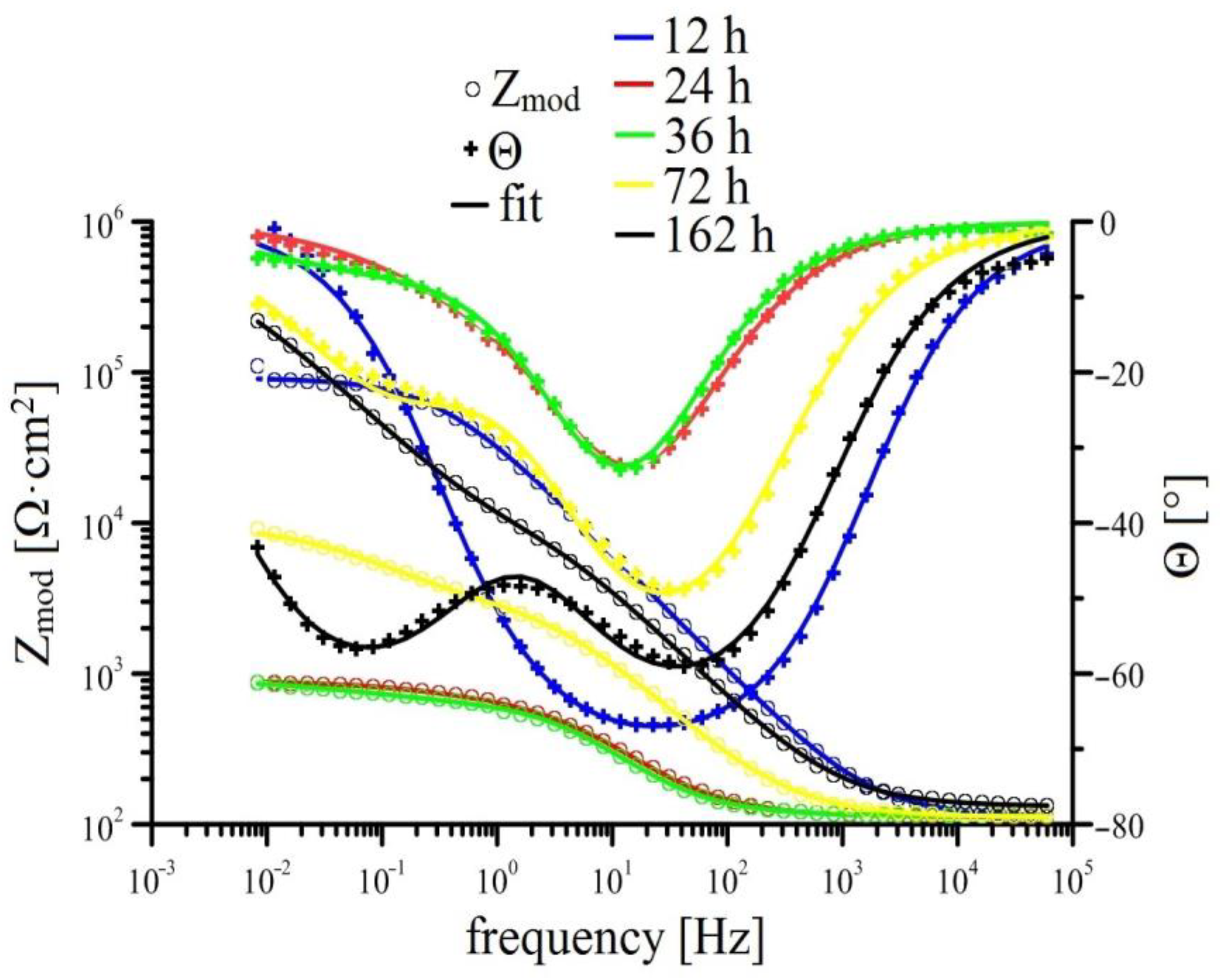
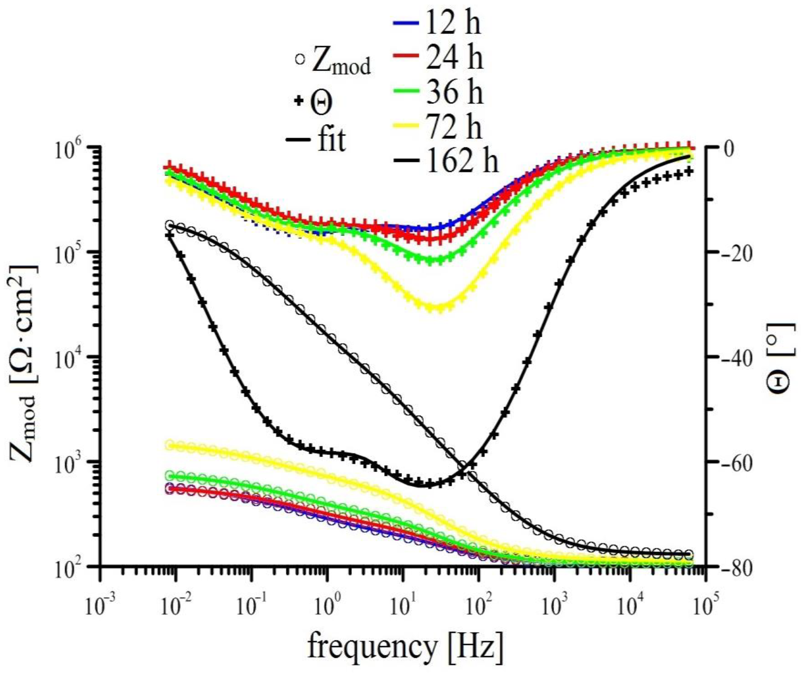
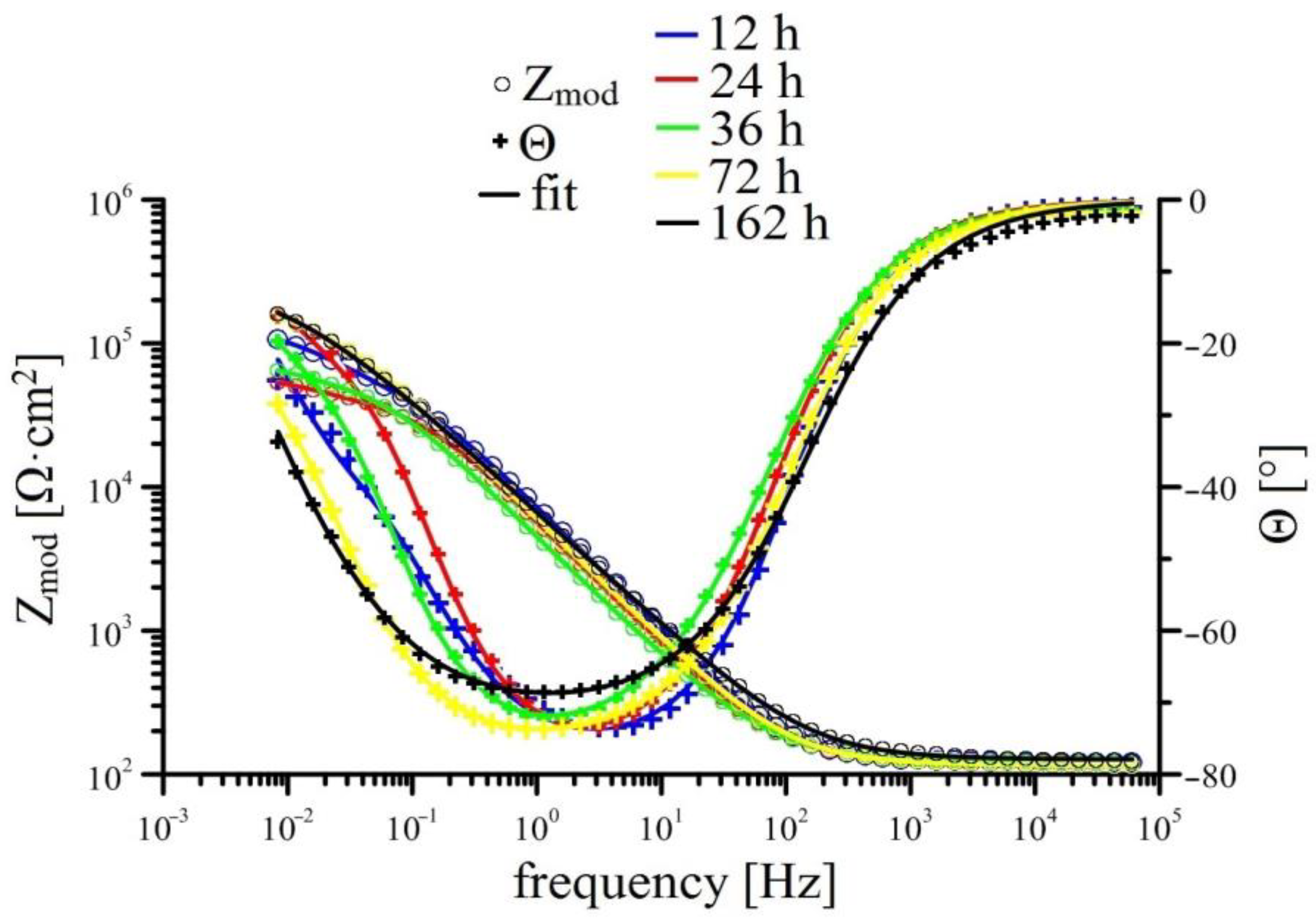
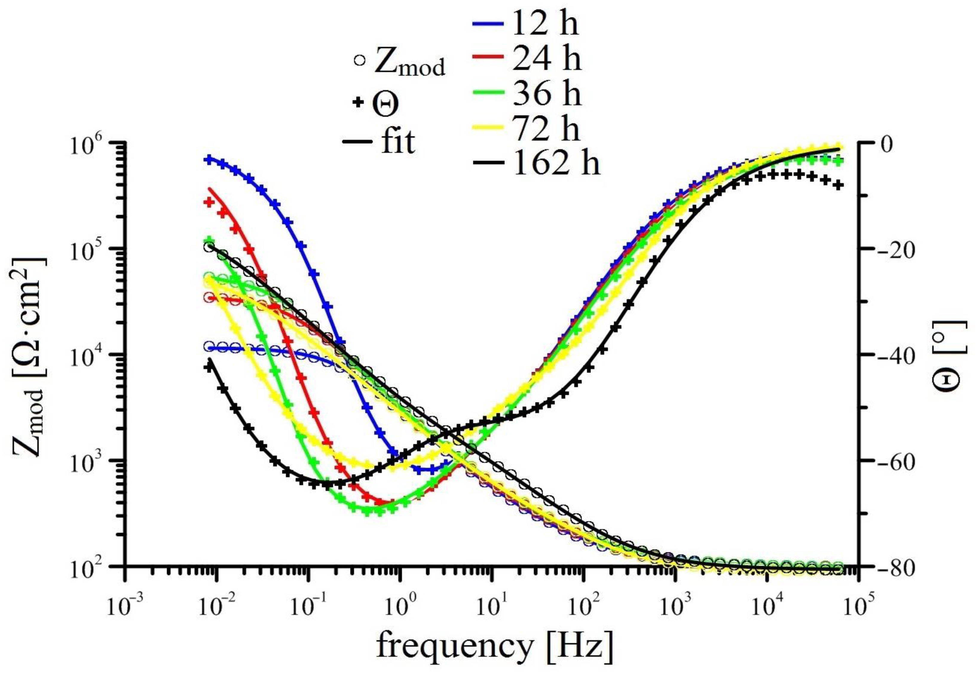
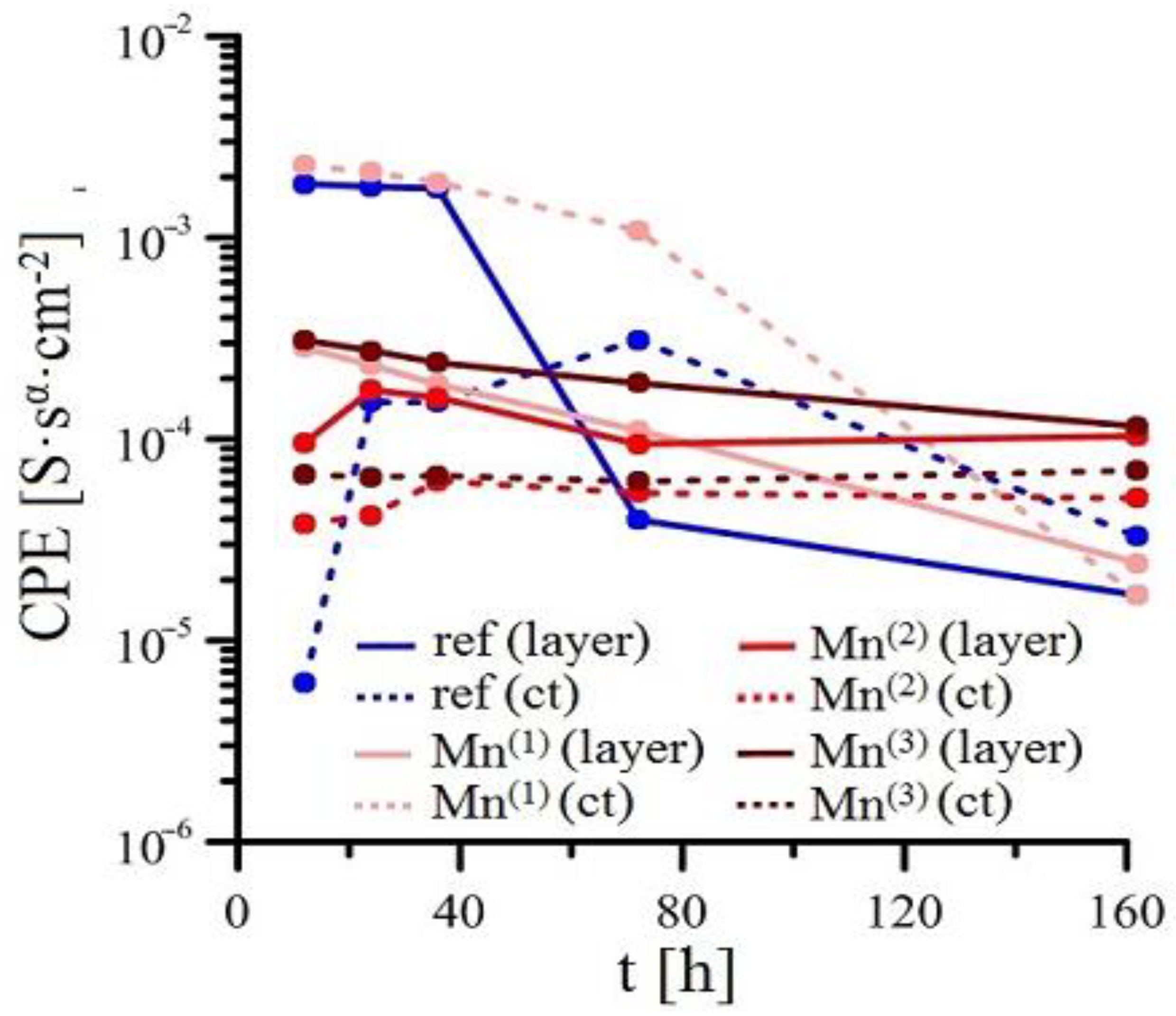
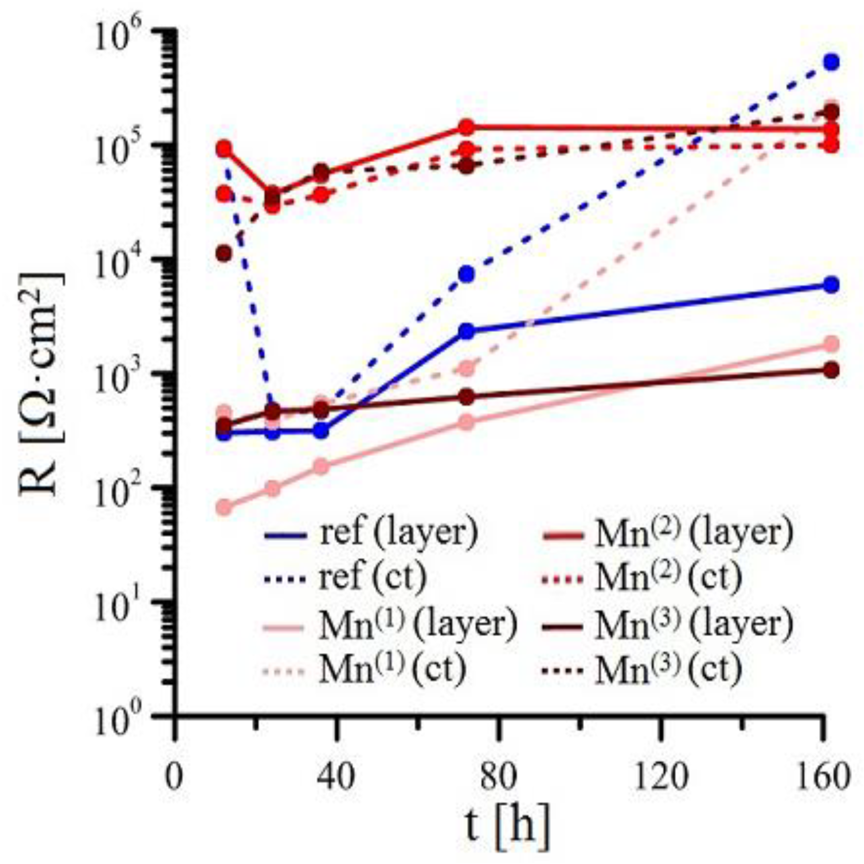
3.2.2. EIS
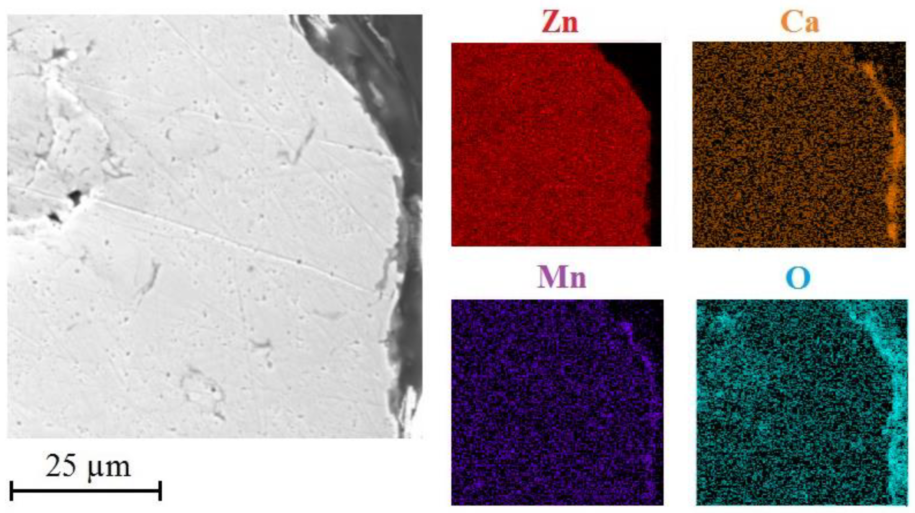
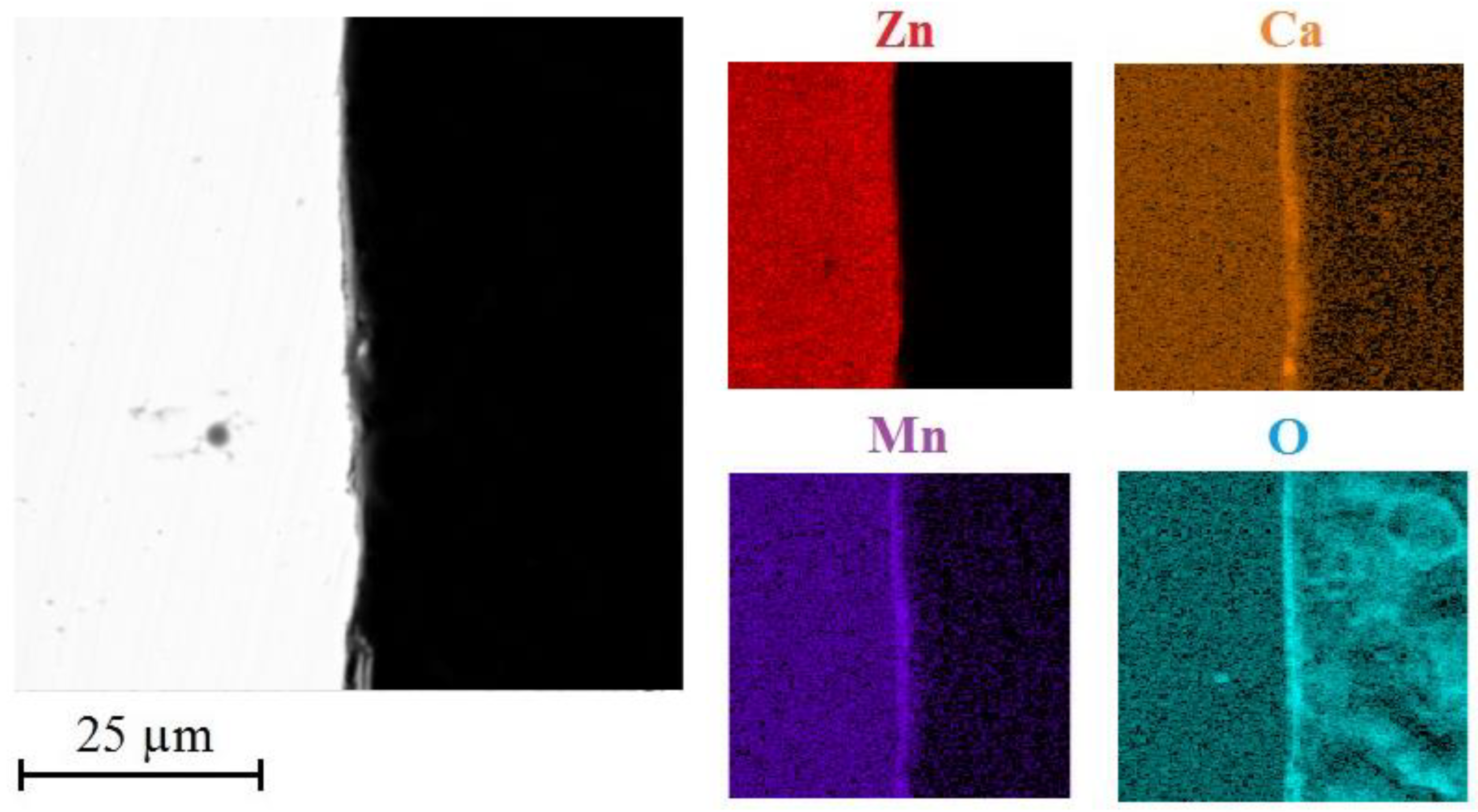
3.3. Analysis of Corrosion Products
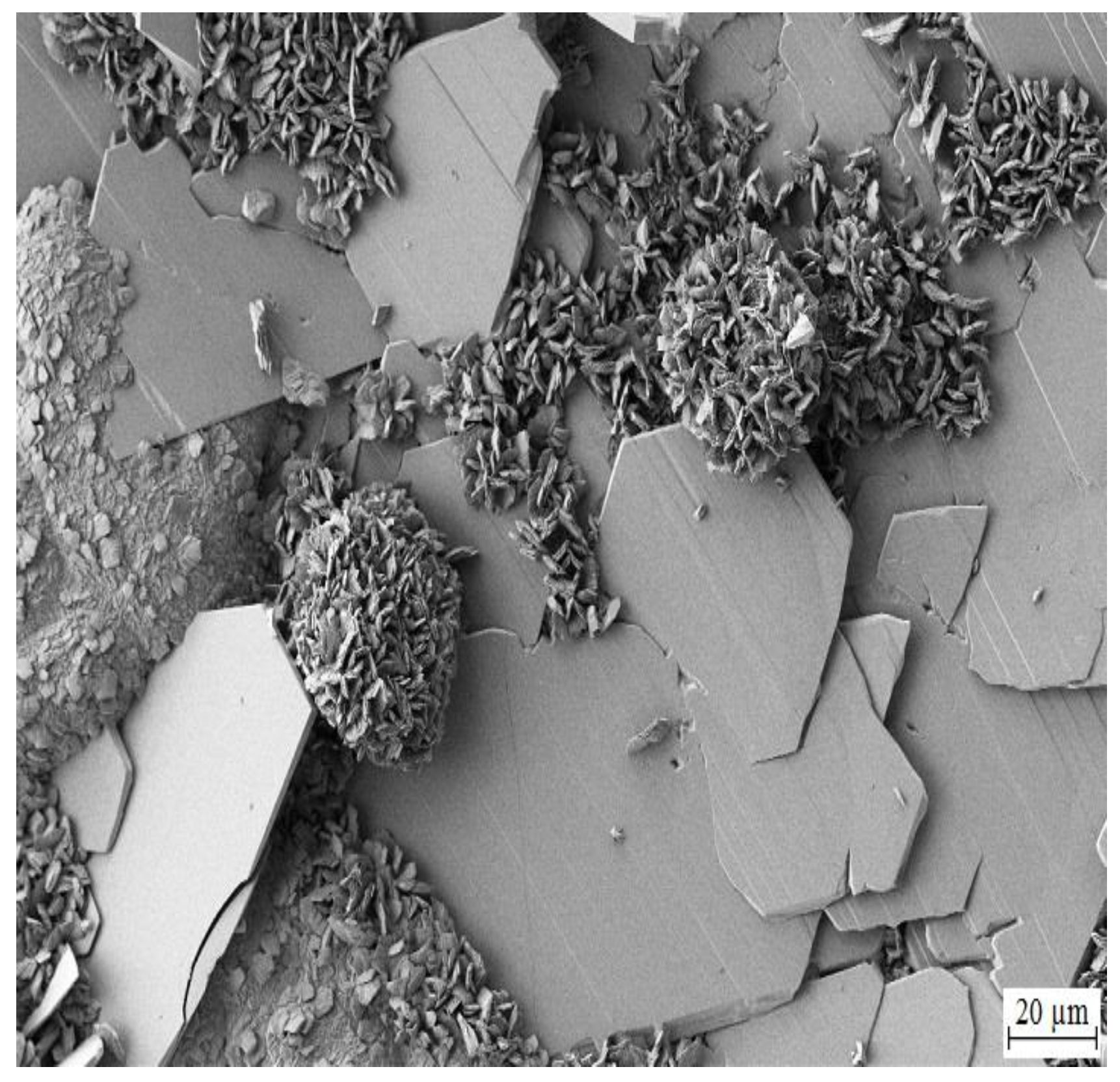
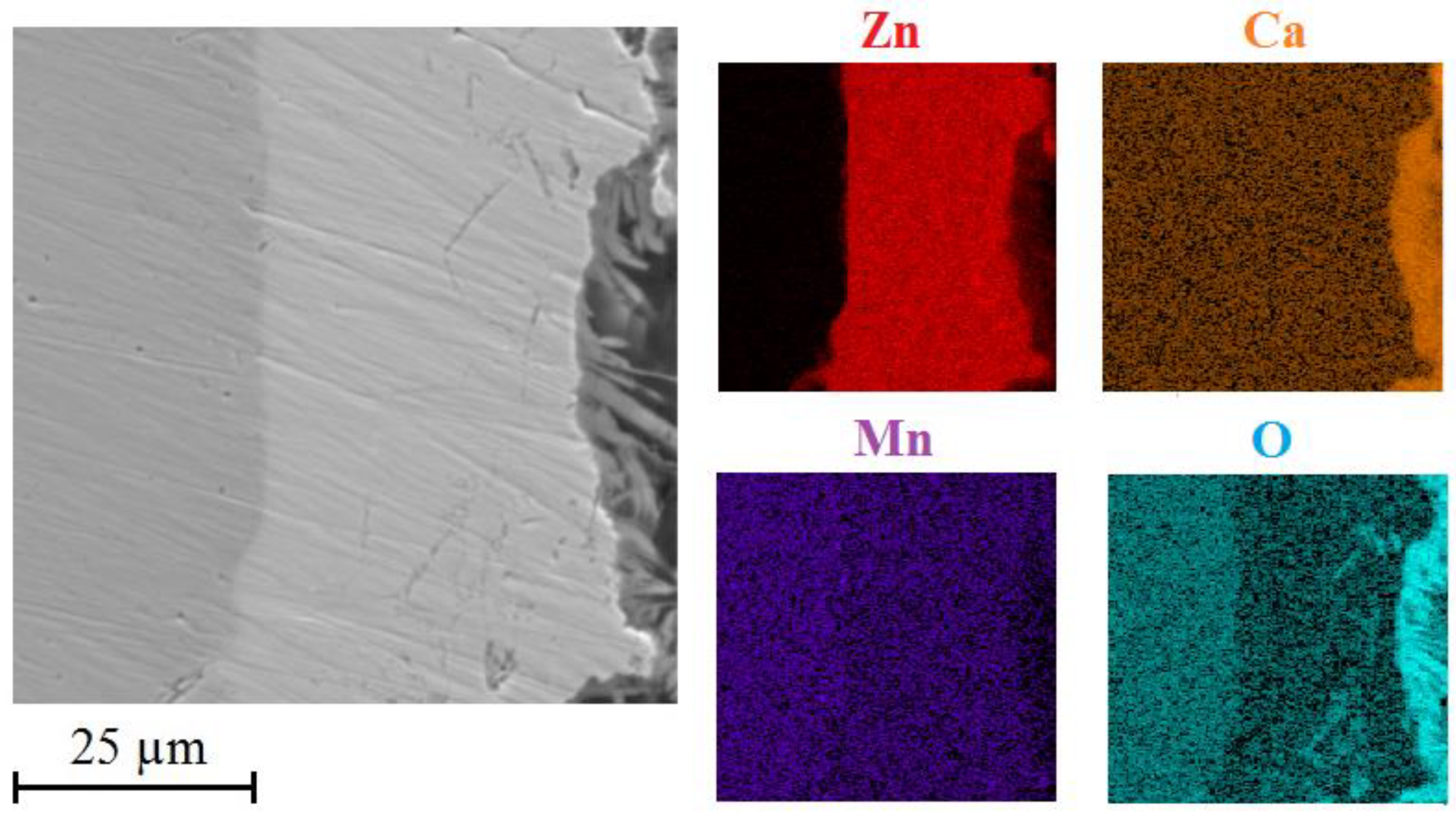
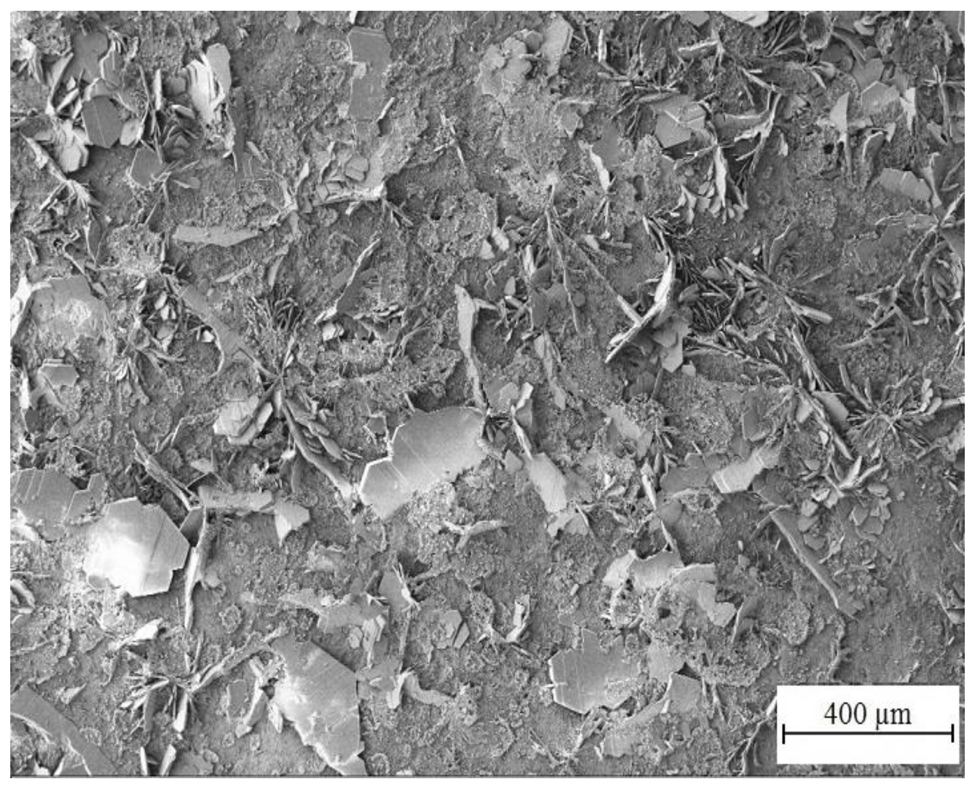
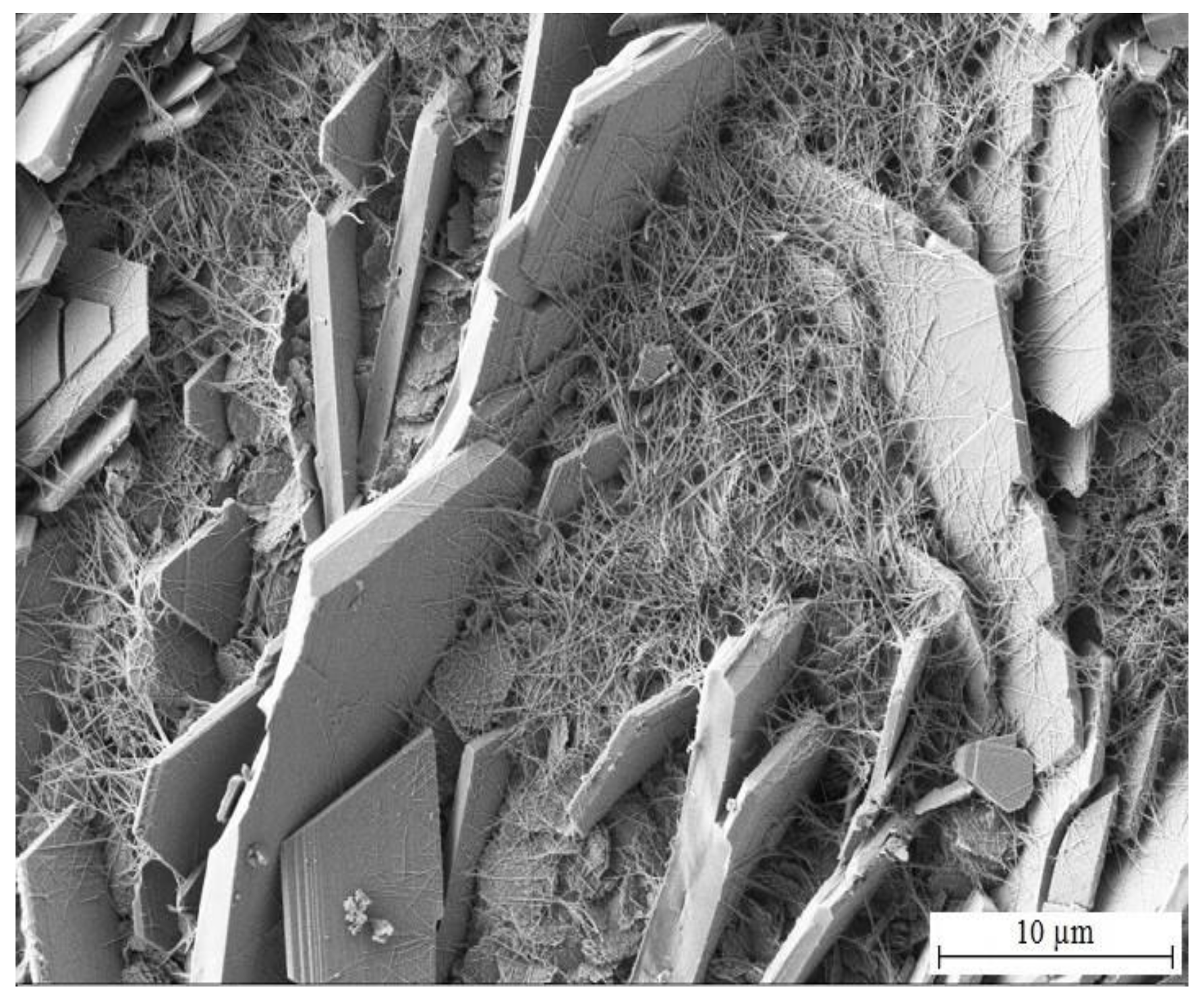
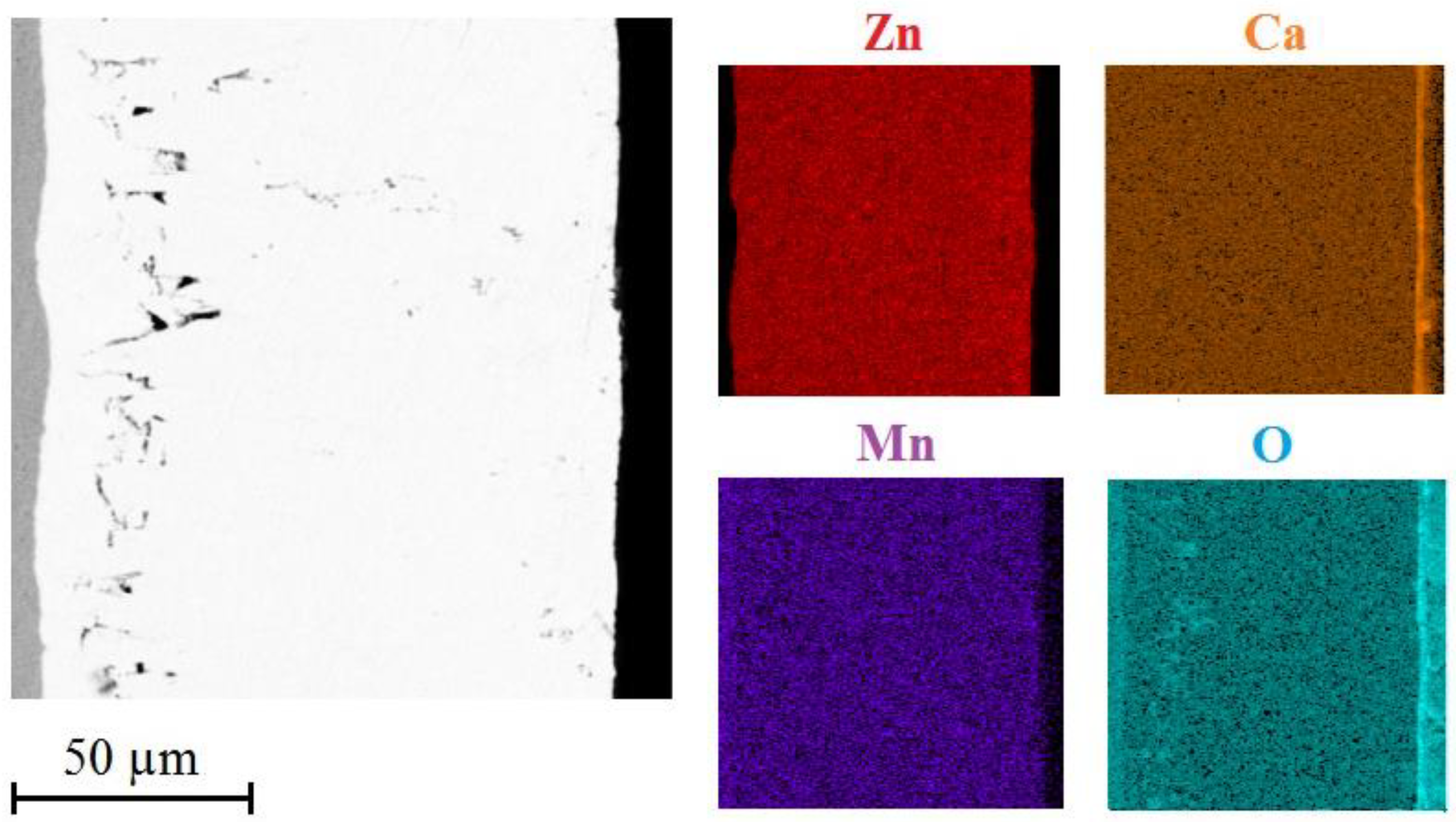
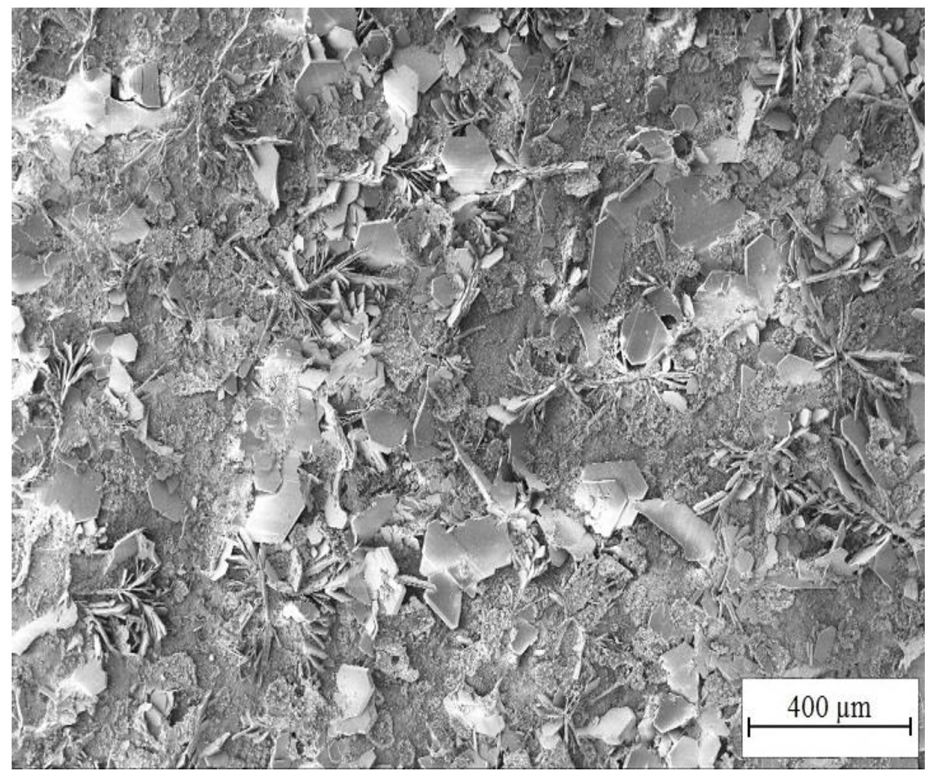
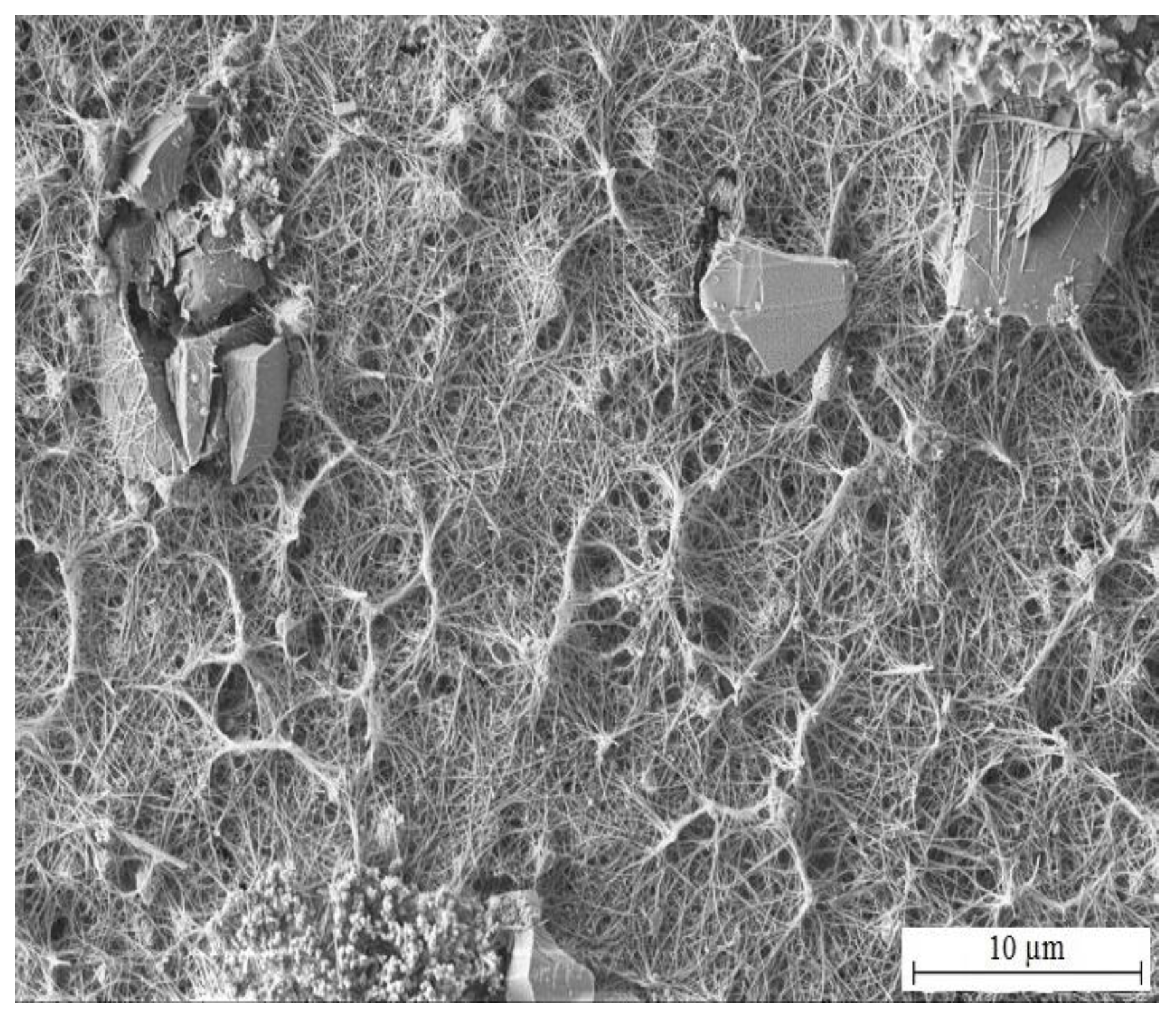
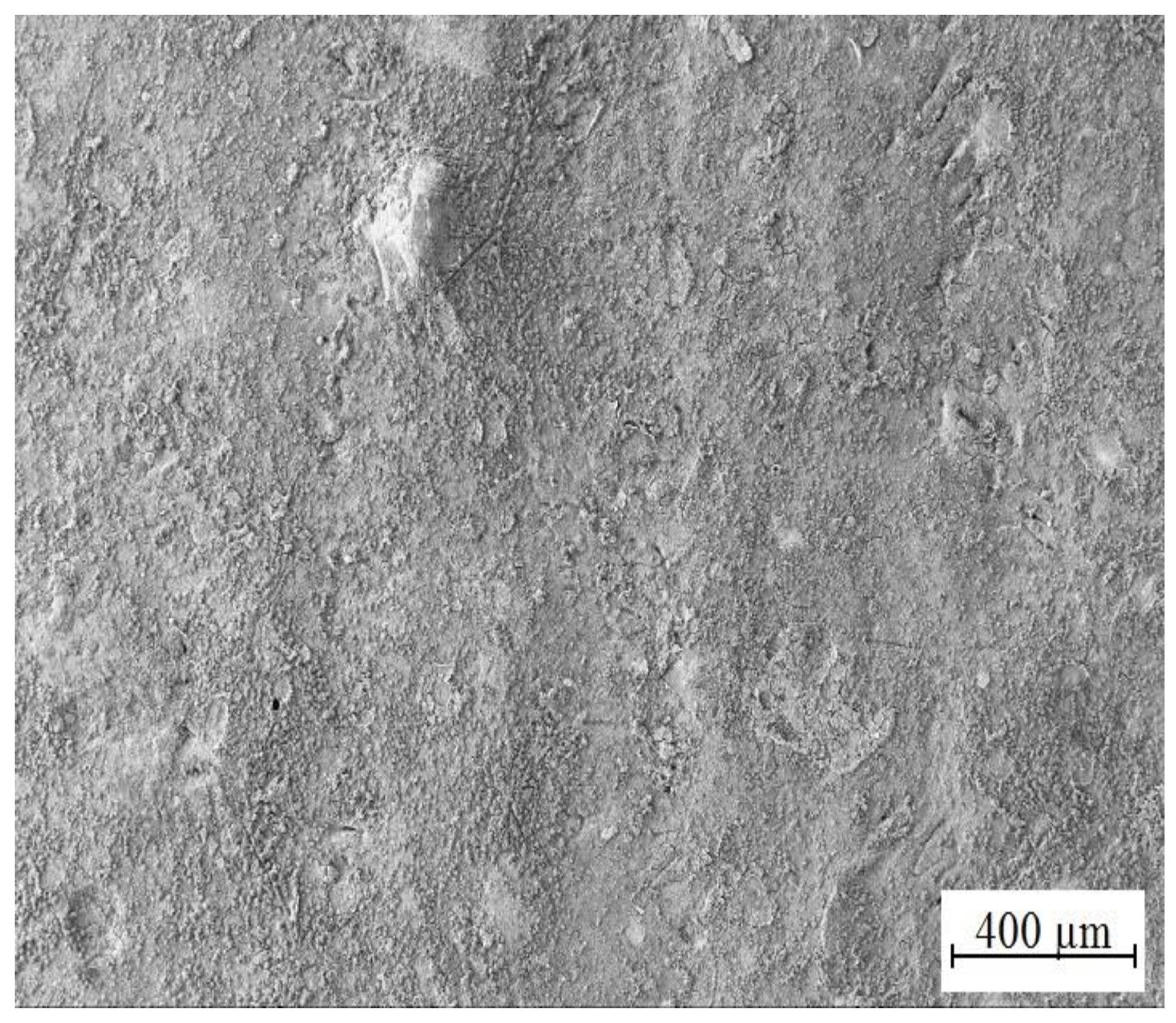
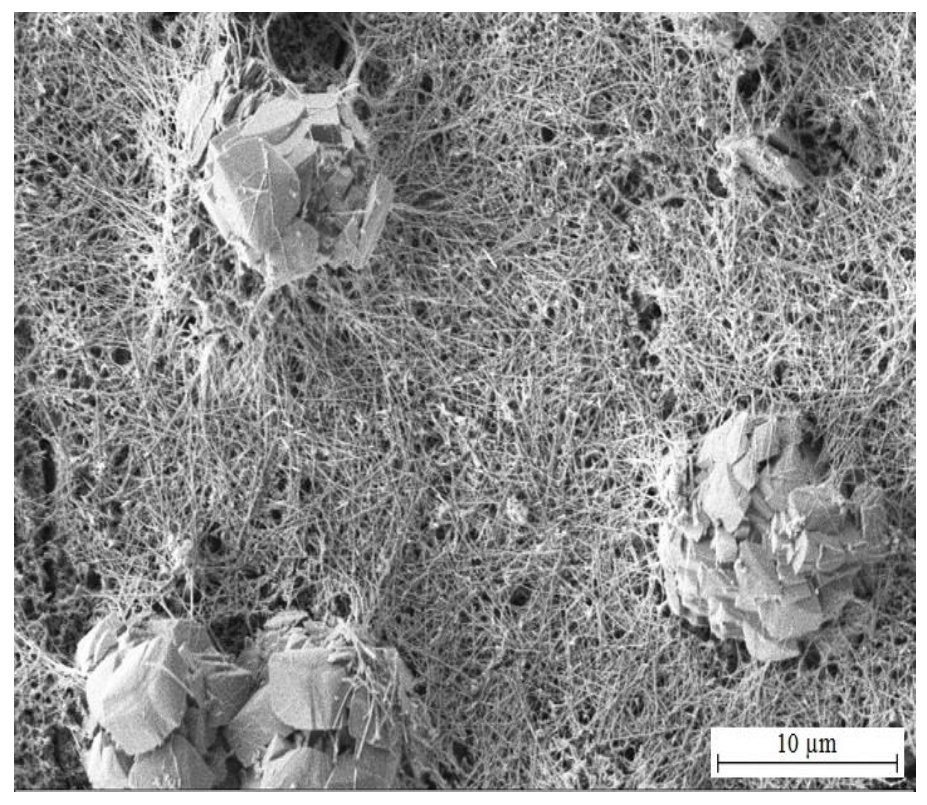
3.3.1. SEM Analysis
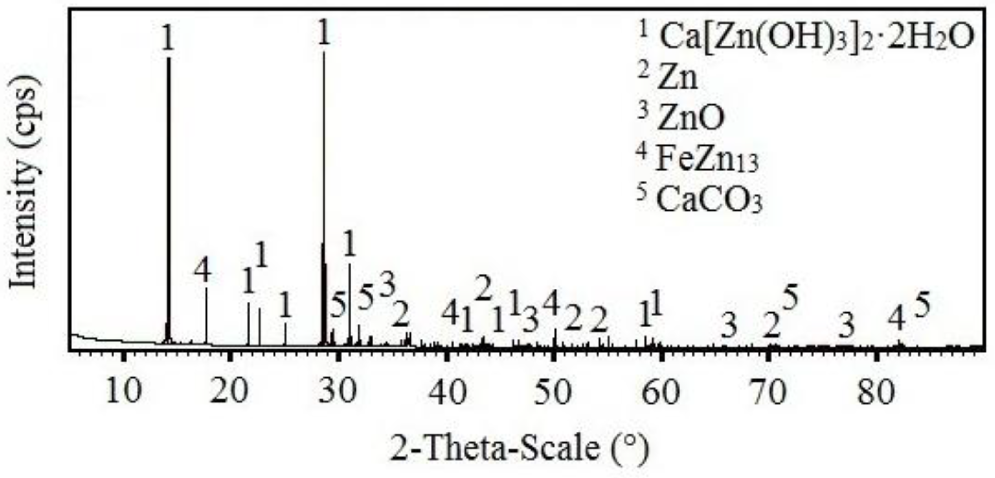
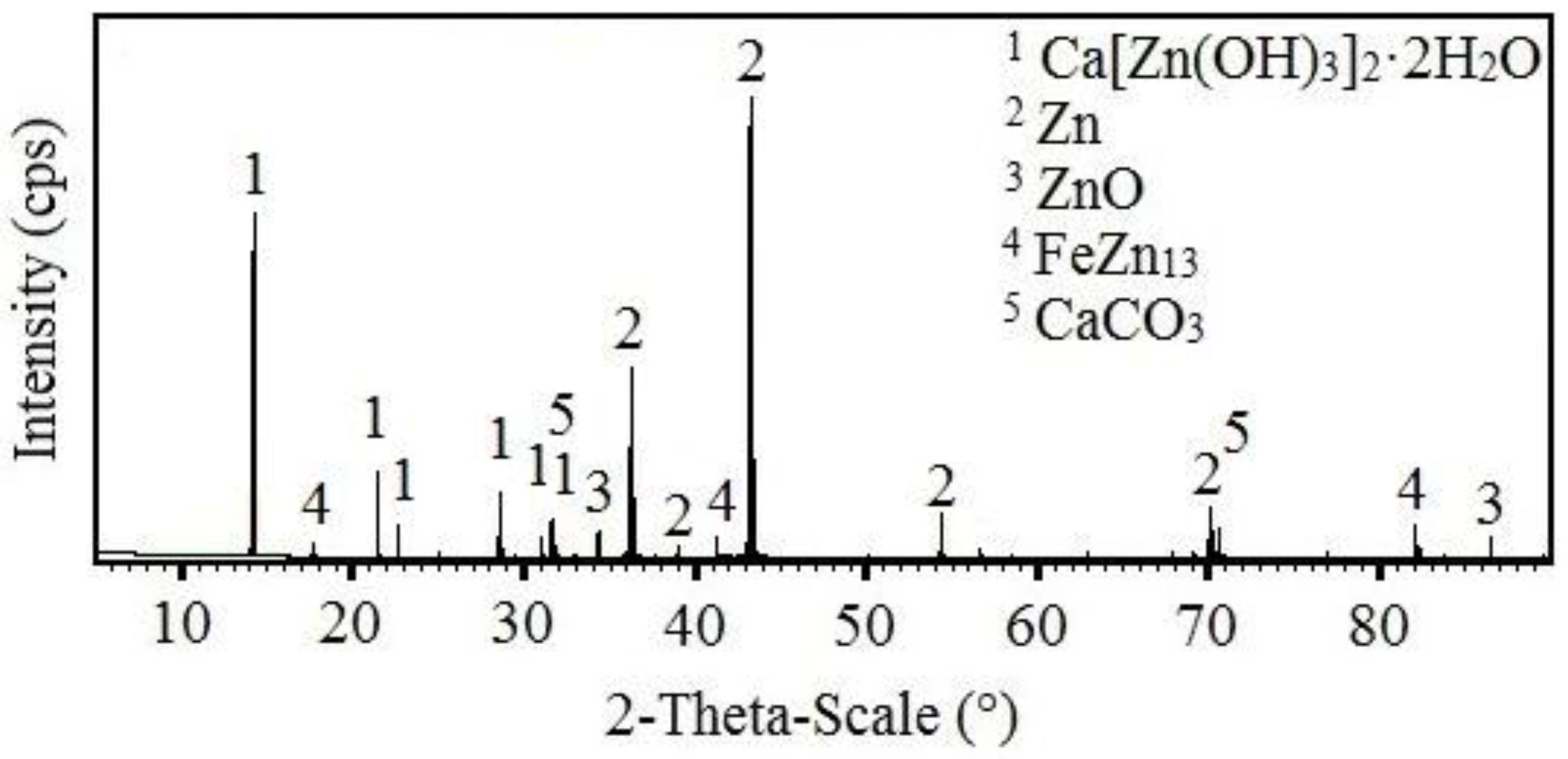
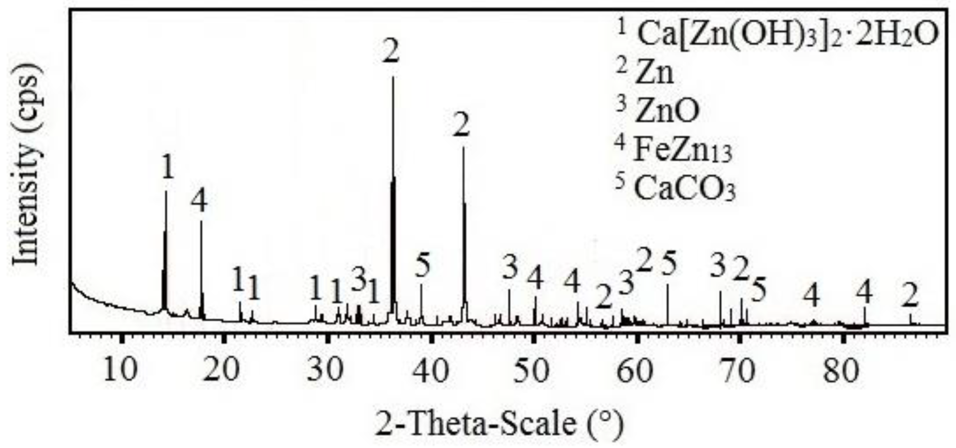
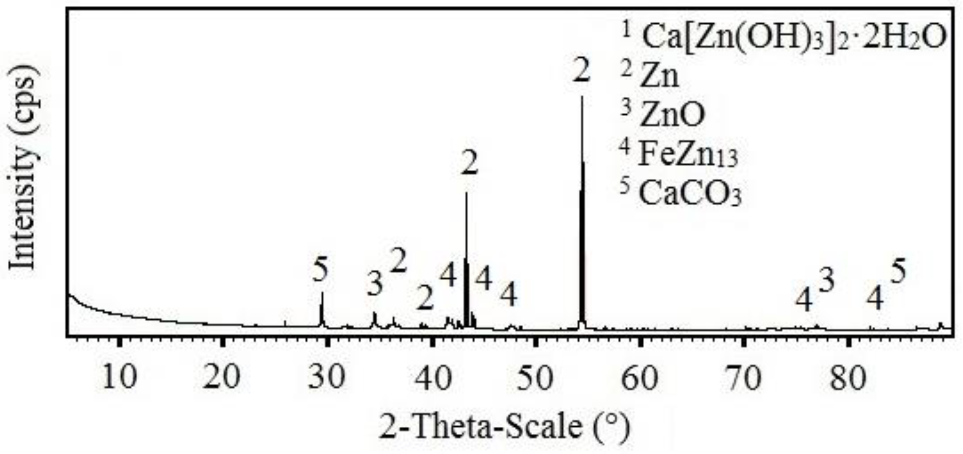
3.3.2. X-ray Diffraction Analysis
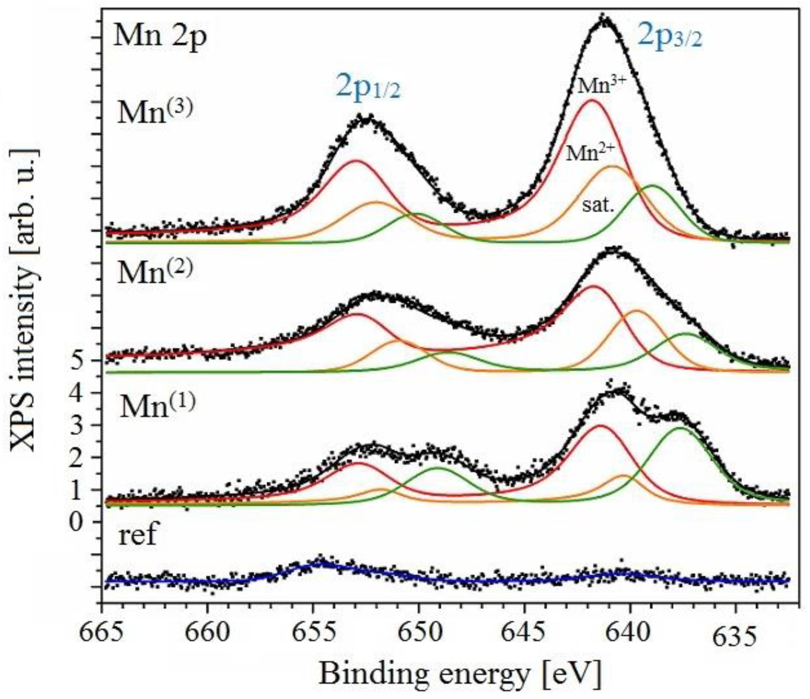
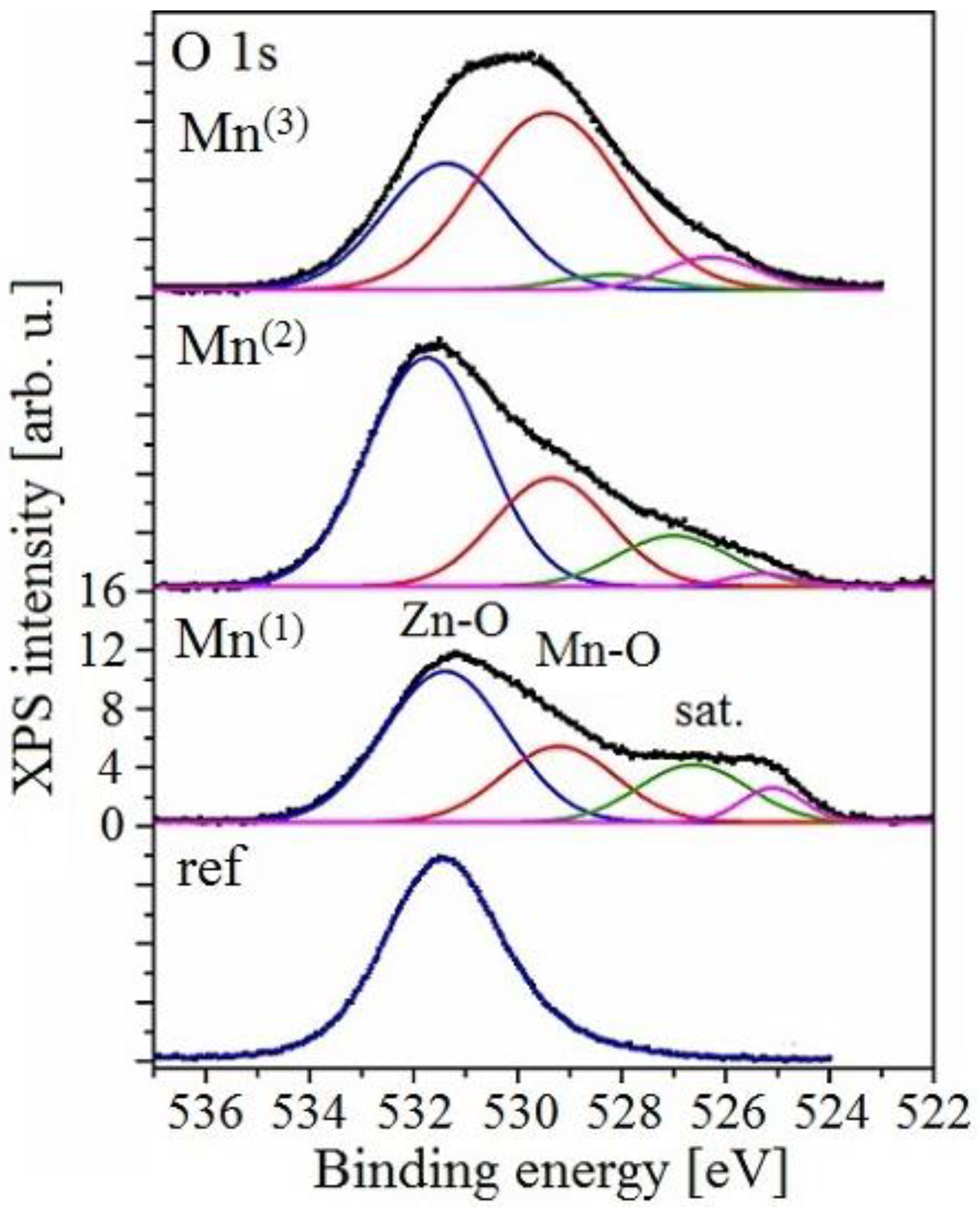
3.3.3. XPS Analysis
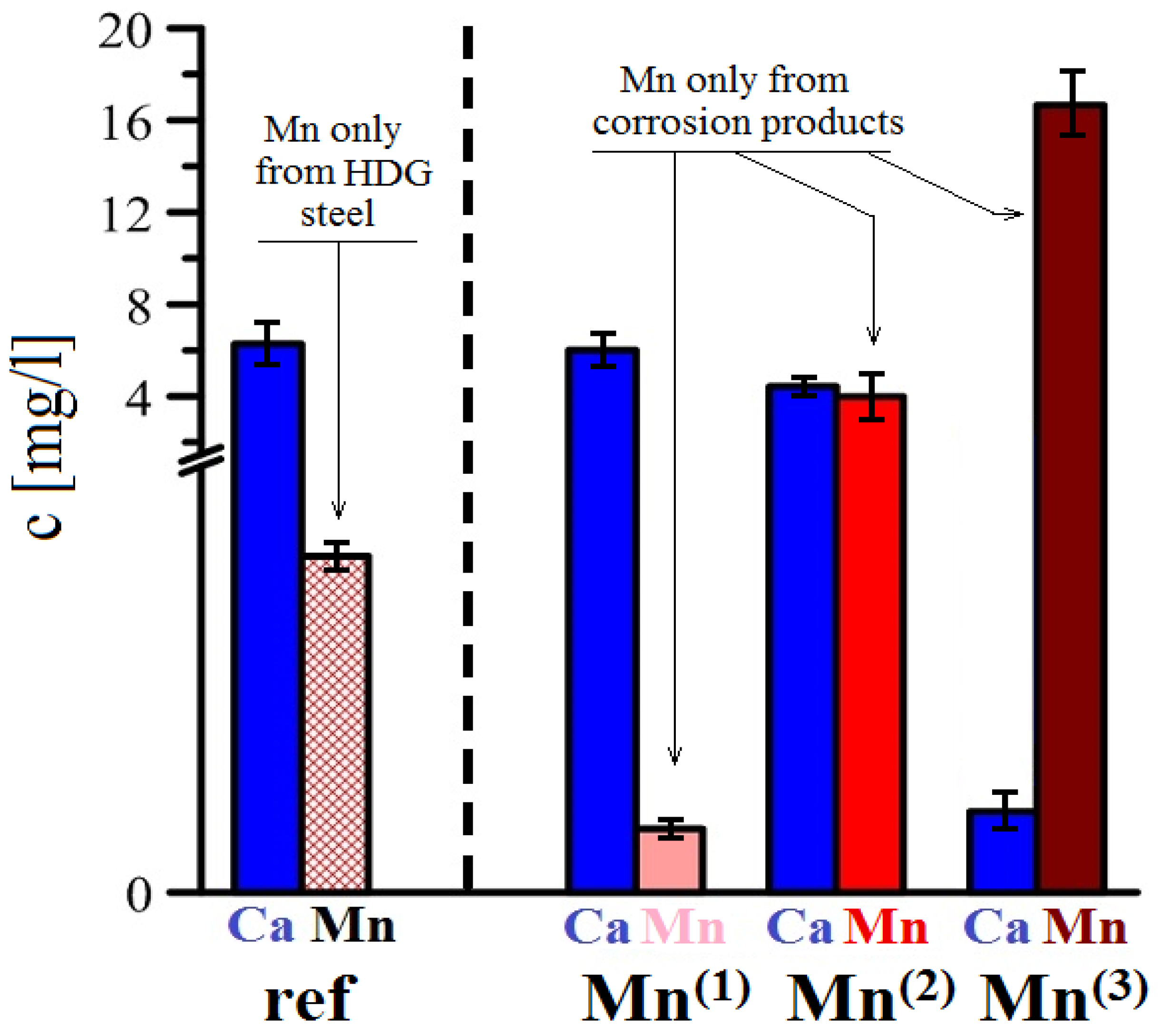
3.3.4. AAS Analysis
4. Conclusions
Author Contributions
Funding
Institutional Review Board Statement
Informed Consent Statement
Data Availability Statement
Conflicts of Interest
References
- Yeomans, S.R. Understanding the corrosion process for galvanized steel reinforcement in concrete. In International Conference on Understanding Corrosion Mechanism of Metals in Concrete; MIT: Boston MA, USA, 1997. [Google Scholar]
- Bowsher, B. Corrosion protection of reinforcing steels. In Technical Report Fib-Bulletin 49; IFSC: Lousanne, Switzerland, 2009. [Google Scholar]
- Yeomans, S.R. Galvanized reinforcing steel. Corr. Mange. 2002, 3–6. [Google Scholar]
- Yeomans, S.R. Galvanized steel reinforcement–a prespect view. In Real World Concrete–Symposium of R. N. Swamy; American Concrete Institute: Farmington Hills, MI, USA, 1995; pp. 55–70. [Google Scholar]
- Farina, S.B.; Duffó, G.S. Corrosion of zinc in simulated carbonated concrete pore solution. Electrochim. Acta 2007, 52, 5131–5139. [Google Scholar] [CrossRef]
- Vera, R.; Venegas, V.M.; Carvajal, A.M.; Corvo, F.; Pérez, T. Performance of carbon steel and galvanized steel in reinforced concrete structures after accelerated carbonation. J. Electrochem. Sci. 2012, 7, 10722–10734. [Google Scholar]
- Ramírez, E.; Gonzáles, J.A.; Bautista, A. The protective efficiency of galvanizing against corrosion of steel in mortar and in Ca(OH)2 saturated solutions containing chlorides. Cem. Concr. Res. 1996, 26, 1525–1536. [Google Scholar] [CrossRef]
- Bautista, A.; Gonzales, J.A. Analysis of the protective efficiency of galvanizing against corrosion of reinforcements embedded in chloride contaminated concrete. Cem. Concr. Res. 1996, 26, 215–223. [Google Scholar] [CrossRef]
- Pokorný, P.; Pernicová, R.; Tej, P.; Kolísko, J. Changes of bond strength properties of hot-dip galvanized plain bars with cement paste after 1 year of curing. Constr. Build. Mater. 2019, 226, 920–931. [Google Scholar] [CrossRef]
- Ghost, R.; Sign, D.D.N. Kinetics, mechanism and characterisation of passive film formed on hot dip galvanized coating exposed in simulated concrete pore solution. Surf. Coat. Technol. 2001, 16–17, 7346–7359. [Google Scholar]
- Zheng, H.; Dai, J.-G.; Hou, L.; Meng, G.; Poon, C.S.; Li, W. Enhanced passivation of galvanized steel bars in nano-silica modified cement mortars. Cem. Conc. Compos. 2020, 111, 103626. [Google Scholar] [CrossRef]
- Gallego, A. Comparison between concrete-black steel and concrete-galvanized steel bond via the pull-out test supplied with acoustic emission. In Proceedings of the European Working Group on Acoustic Emission, Berlin, Germany, 15–17 September 2004; pp. 761–767. [Google Scholar]
- Guklid, I.; Hofsøy, A. Hot Dip Galvanized Steel Reinforcement (Varmforsinket Armeringsstål); Teknisk Ukeblad Oslo: Oslo, Norway, 1965; pp. 37–43. [Google Scholar]
- Pokorný, P.; Kostelecká, M.; Prodanovic, N.; Sýkora, M. Effect of calcium hydroxyzincate on bond strength of hot-dip galvanized plain bars with normal strength concrete. Cem. Conc. Compos. 2022, 130, 104540. [Google Scholar] [CrossRef]
- Zheng, H.; Dai, J.-G.; Poon, C.S.; Li, W. Influence of calcium ion in concrete pore solution on the passivation of galvanized steel bars. Cem. Concr. Res. 2018, 108, 46–58. [Google Scholar] [CrossRef]
- Maeda, M.; Li, X.; Ooi, A.; Tada, E.; Nishikata, A. Passivation mechanism of galvanized steel rebar in fresh concrete. ISIJ Int. 2020, 60, 337–345. [Google Scholar] [CrossRef] [Green Version]
- Roventi, G.; Bellezze, T.; Giuliani, G.; Conti, C. Corrosion resistance of galvanized steel reinforcements in carbonated concrete: Effect of wet-dry cycles in tap water and in chloride solution on the passivating layer. Cem. Concr. Res. 2014, 65, 76–84. [Google Scholar] [CrossRef]
- Tittarelli, F.; Bellezze, T. Investigation of the major reduction reaction occurring during the passivation of galvanized steel rebars. Corros. Sci. 2010, 52, 978–983. [Google Scholar] [CrossRef]
- Tan, Z.Q.; Hansson, C.M. Effect of surface condition on the initial corrosion of galvanized reinforcing steel embedded in concrete. Corros. Sci. 2008, 50, 2512–2522. [Google Scholar] [CrossRef]
- Menzel, K. Zur Korrosion Von Verzinktem Stahl in Kontakt Mit Beton–IWB (Mitteilungen); Universität Stuttgart: Stuttgart, Germany, 1992. [Google Scholar]
- Wienerová, K.; Kouřil, M.; Stoulil, J. Koroze a ochrana zinkované oceli v prostředí betonu. Koroze A Ochr. Mater. 2010, 54, 148–154. [Google Scholar]
- Belaïd, F.; Arliguie, G.; Francois, R. Porous structure of ITZ around galvanized and ordinary steel reinforcements. Cem. Concr. Res. 2001, 31, 1561–1566. [Google Scholar] [CrossRef]
- Belaïd, F.; Arliguie, G.; Francois, R. Effect of bars properties on bond strength of galvanized reinforcement. J. Mater. Civ. Eng. 2001, 13, 454–458. [Google Scholar] [CrossRef]
- Yeomans, S.R. Comparative Studies of Galvanized and Epoxy Coated Steel Reinforcement in Concrete; Research Report No. R103; The University of New South Wales-Canberra: Sydney, Australia, 1991; pp. 1–15. [Google Scholar]
- Rovnaníková, P.; Bayer, P. Microstructure of hardened Portland cement paste in galvanized reinforcement sourroundings. In Proceedings: 9–The Association of Czech and Slovak Galvanizing; AČSZ: Ostrava, Czech Republic, 2003; pp. 57–62. [Google Scholar]
- Ryant, L.; Vorel, J.; Řepík, M. Kotvení Pozinkované Výztuže, Výzkumná Zpráva ze Středoškolské Odborné Činnosti. Ph.D. Thesis, Stavební Škola J. Gočára, Prague, Czech Republic, 2008. [Google Scholar]
- Rovnaníková, P.; Bayer, P. Study of the interfacial transition zone between cement paste and zinc coated steel reinforcement. In Proceedings of the 13th International Conference Corrosion of Underground Structures 2003, Košice, Slovakia, 27–28 May 2003; pp. 65–70. [Google Scholar]
- Figueira, R.B.; Silva, C.J.R.; Pereira, E.V.; Salta, M.M. Corrosion of hot-dip galvanized steel reinforcement. Corros. Prot. Mater. 2014, 33, 51–61. [Google Scholar]
- Zhang, G. Formation mechanisms of environmentally acceptable chemical conversion coatings for zinc: A review. J. Coat. Technol. Res. 2019, 16, 1–13. [Google Scholar]
- Fratesi, R.; Moriconi, G.; Coppola, L. The Influence of Steel Galvanization on Rebars Behaviour in Concrete, Corrosion of Reinforcement in Concrete Construction; The Royal Society of Chemistry: London, UK, 1996; pp. 630–640. [Google Scholar]
- Proctor, D.M.; Suh, M.; Campleman, S.L.; Thompson, C.M. Assessment of the mode of action for hexavalent chromium-induced lung cancer following inhalation exposures. Toxicology 2014, 325, 160–179. [Google Scholar] [CrossRef]
- Prošek, T. Konverzní a organické povlaky s chromem v oxidačním stavu VI a jejich alternativy. Koroze A Ochr. Mater. 2005, 49, 27–33. [Google Scholar]
- Kouřil, M. Koroze pozinkované oceli v modelovém pórovém roztoku betonu. In Proceedings: 9–The Association of Czech and Slovak Galvanizing; AČSZ: Ostrava, Czech Republic, 2003; pp. 23–30. [Google Scholar]
- La, D.; Jiang, Y.; Wang, Y.; Kong, G.; Che, C. Improved corrosion resistance of galvanized steel with a zinc phosphate coating in alkaline solution. Int. J. Electrochem. Sci. 2020, 15, 4853–4868. [Google Scholar] [CrossRef]
- Arenas, M.A.; Casado, C.; Nobel-Pujol, V.; de Damborene, J. Influence of the conversion coating on the corrosion of galvanized reinforcing steel. Cem. Conc. Compos. 2006, 28, 267–275. [Google Scholar] [CrossRef]
- Arenas, M.A.; de Damborene, J. Surface charactarisation of cerium layers on galvanised steel. Surf. Coat. Technol. 2004, 187, 320–325. [Google Scholar] [CrossRef]
- Burchett, K.R. Metal Treatment to Prevent Corrosion and Blemishes in Metal Reinforced Concrete Structures. U.S. Patent 3,619,441, 9 November 1971. [Google Scholar]
- Bailey, R.W.; Ridge, H.G. Corrosion of metals in buildings. Chem. Ind. 1957, 4, 1222–1227. [Google Scholar]
- Schikorr, G. Einige Zerstörungserscheinungen an Aluminium, Eisen und Zink in Mauerwerk. Wiss. Abh. Dtsch. Mater. 1941, 2, 51–54. [Google Scholar]
- Bird, C.E. The influence of minor constituents in Portland cement on the behavior of galvanized steel in concrete. Corros. Prev. Control. 1964, 2, 17–21. [Google Scholar]
- Yeoamns, S.R. Galvanized Steel Reinforcement in Concrete; Elsevier: Canberra, Australia, 2004. [Google Scholar]
- Mang, R.; Müller, R.H. Untersuchungen zur Anwendbarkeit feuerverzinkter Bevehrung im Stahlbeton-bau. Stahl Und Eisen 1982, 889–894. [Google Scholar]
- Corderoy, D.J.H.; Herzog, H. Passivation of Galvanized Reinforcement by Inhibitor Anions. Corrosion of Reinforcing Steel in Concrete; ASTM: West Conshohocken, PA, USA, 1978; pp. 142–159. [Google Scholar]
- Roberts, A.W.; Scott, O.J.; Leung, H.K. Bond Characteristics of Concrete Reinforcing Tendons Coated with Zinc; Project ZE 222-ILZRO; International Lead Zinc Research Orhanization: Durham, NC, USA; Research Triangle Park, NC, USA, 1978. [Google Scholar]
- Belleze, T.; Monosi, S.; Roventi, G.; Fratesi, R. Inhibition of Galvanized Rebars Active Corrosion in Fresh Concrete Using Hydrogen Peroxide; EUROCORR: Estoril, Portugal, 2012. [Google Scholar]
- Li, M.C.; Royer, M.; Stien, D.; Lecante, A.; Roos, C. Inhibitive effect of sodium eperuate on zinc corrosion in alkaline solutions. Corr. Sci. 2008, 50, 1975–1981. [Google Scholar] [CrossRef]
- Lambrechts, A.; Vanbrabant, J. Reinforced Structure Comprising a Cementitious Matrix and Zinc Coated Elements. U.S. Patent 2010/0021759A1, 28 January 2010. [Google Scholar]
- Błaszczak-Świątkiewicz, K.; Sikora, J.; Szymański, J.; Danilewicz, M.; Mikiciuk-Olasik, E. Biological evaluation of the toxicity and the cell cycle interruption by some benzimidazole derivatives. Tumor Biology 2016, 37, 11135–11145. [Google Scholar] [CrossRef] [Green Version]
- Mohareb, R.M.; Abdallah, A.E.M.; Mohamed, A.A. Synthesis of novel thiophene, thiazole and coumarin derivates based on benzimidazole nucleus and their cytotoxicity and toxicity evaluations. Chem. Pharm. Bull. 2018, 66, 309–318. [Google Scholar] [CrossRef] [PubMed]
- Wang, Y.; Kong, G. Corrosion inhibition of galvanized steel by MnO4- ion as a soluble inhibitor in simulated fresh concrete environment. Constr. Build. Mater. 2020, 257, 119532. [Google Scholar] [CrossRef]
- Wang, Z.; Liu, L.; Zhou, J.; Zhou, C. Impacts of potassium permanganate (KMnO4) catalyst on properties of hydrogen peroxide (H2O2) foamed porous cement slurry. Constr. Build. Mater. 2016, 111, 72–76. [Google Scholar] [CrossRef]
- Yin, K.; Li, F.; Wang, Y.; He, Q.; Deng, Y.; Chen, S.; Liu, C. Oxidative transformation of artificial sweetener acesulfame by permanganate: Reaction kinetics, transformation products and pathways, and ecotoxicity. J. Hazar. Mater. 2017, 330, 52–60. [Google Scholar] [CrossRef] [PubMed]
- Willhite, C.C.; Bhat, V.S.; Ball, G.L.; McLellan, C.J. Emergency do not consume/ do not use concentations for potassium permanganate in drinking water. Hum. Exp. Toxicol. 2013, 32, 275–298. [Google Scholar] [CrossRef]
- Česen, A.; Kosec, T.; Legat, A.; Boken-Bosiljkov, V. Corrosion properties of different forms of carbon steel in simulated concrete pore water. Mater. Technol. 2014, 48, 51–57. [Google Scholar]
- Li, L.; Sagüés, A.A.; Poor, N. In situ leaching investigation of pH and nitrite concentration in concrete pore solution. Cem. Concr. Res. 1999, 29, 315–321. [Google Scholar] [CrossRef]
- Baucke, F.G.K. The modern understanding of the glass electrode response. Fresenius J. Anal. Chem. 1994, 349, 582–596. [Google Scholar] [CrossRef]
- Camoes, M.F.G.F.C.; Covington, A.K. New procedure for calibrating glass electrodes. Anal. Chem. 1974, 46, 1547–1551. [Google Scholar] [CrossRef]
- Karlberg, B.; Johansson, G. Alkaline errors of glass electrodes in non-aqueous solvents. Talanta 1969, 16, 1545–1551. [Google Scholar] [CrossRef]
- Wikby, A. The surface resistance of glass electrodes in alkaline solutions. J. Electroanal. Chem. Interfacial Electrochem. 1972, 39, 103–109. [Google Scholar] [CrossRef]
- Yuana, T.; Wang, J.; Li, Z. Measurement and modelling of solubility for calcium sulfate dihydrate and calcium hydroxide in NaOH/KOH solutions. Fluid Phase Equilibria 2010, 297, 129–137. [Google Scholar] [CrossRef]
- Duchesne, J.; Reardon, E.J. Measurement and prediction of portlandite solubility in alkali solutions. Cem. Concr. Res. 1995, 25, 1043–1053. [Google Scholar] [CrossRef]
- Macphee, D.E.; Luke, K.; Glasser, F.P.; Lachowski, E.E. Solubility and aging of calcium siicate hydrates in alkalinesolutions at 25 °C. J. Am. Ceram. Soc. 1989, 72, 646–654. [Google Scholar] [CrossRef]
- Marder, A.R. The metallurgy of zinc-coated steel. Prog. Mater. Sci. 2000, 45, 191–271. [Google Scholar] [CrossRef]
- Nishimoto, A.; Inagaki, J.; Nakaoka, K. Effect of surface microstructure and chemical compositions of steels on formation of Fe-Zn componds during continuous galvanizing. Trans. ISIJ 1986, 26, 807–813. [Google Scholar] [CrossRef]
- Shibli, S.M.A.; Meena, B.N.; Remya, R. A review on recent approaches in the field of hot dip galvanizing process. Surf. Coat. Technol. 2015, 262, 210–215. [Google Scholar] [CrossRef]
- Yu, J.; Liu, J.; Zhou, W.; Zhang, J.; Wu, J. Cross-sectional TEM observation of iron-zinc intermetallic Γ and Γ1 phases in commercial galvannealed IF steel sheets. Mater. Des. 2007, 28, 249–253. [Google Scholar] [CrossRef]
- Okamoto, N.L.; Yasuhara, A.; Inui, H. Order-disorder structure of the δ1k phase in the Fe-Zn system determined by scanning transmission electron microscopy. Acta Mater. 2014, 81, 345–357. [Google Scholar] [CrossRef] [Green Version]
- Okamoto, N.L.; Tanaka, K. Structure refinement of the δ1p phase in the Fe-Zn system by single-crystal X-ray diffraction combined with scanning transmission electron microscopy. Acta Crystallogr. B 2014, 70, 275–282. [Google Scholar] [CrossRef] [Green Version]
- Belin, R.; Tillard, M.; Monconduit, L. Redetermination of the iron-zinc phase FeZn13. Acta Crystallogr. C 2000, 56, 267–268. [Google Scholar] [CrossRef] [PubMed]
- Okamoto, N.L.; Inomoto, M.; Adachi, H.; Takebayashi, H.; Inui, H. Micropillar compression deformation of single crystals of the intermetallic compound ζ–FeZn13. Acta Mater. 2014, 65, 229–239. [Google Scholar] [CrossRef]
- Chen, Y.; Zhu, Y.; Peng, H.; Ya, L.; Su, X.; Wang, J. Influence of phosphorus on the growth of Fe-Zn intermetallic compound in Zn/Fe diffusion couples. Surf. Coat. Technol. 2014, 240, 63–69. [Google Scholar] [CrossRef]
- Sepper, S.; Peetsalu, P.; Saarna, M. Methods for evaluating the appearance of hot dip galvanized coatings. Argonomy Res. 2011, 1, 229–236. [Google Scholar]
- Macias, A.; Andrade, C. Corrosion of galvanized steel reinforcements in alkaline solutions (Part 1: Electrochemical results). Br. Corros. J. 1987, 22, 113–118. [Google Scholar] [CrossRef]
- Macias, A.; Andrade, C. Stability of the calcium hydroxyzincate protective layer developer on galvanized reinforcements after a further increase of the pH value. Mater. Constr. 1986, 36, 19–28. [Google Scholar]
- Andrade, C.; Macias, A. Galvanized Reinforcement in Concrete; Wilson, D., Nicholson, J.W., Prosser, H.J., Eds.; Surface Coatings; Elsevier Applied Science Publishers Ltd.: Amsterdam, The Netherlands, 1998; Volume 2, pp. 137–182. [Google Scholar]
- Santos, P. Influencia de la Estructura Metalográfica y del Tipo de Cemento en la Corrosión de Armaduras Galvanizadas. Ph.D. Thesis, Universidad Autonóma de Madrid, Madrid, Spain, 1986. [Google Scholar]
- Sergi, G.; Short, N.R.; Page, C.L. Corrosion of galvanized and galvannealed steel in solutions of pH 9.0 to 14.0. Corrosion 1985, 41, 618–624. [Google Scholar] [CrossRef]
- Maahn, E.; Sorensen, B. The influence of microstructure on the corrosion properties of hot-dip galvanized reinforcement in concrete. Corrosion 1986, 42, 187–196. [Google Scholar] [CrossRef]
- Short, N.R.; Zhou, S.; Dennis, J.K. Electrochemical studies on the corrosion of a range of zinc alloy coated steel in alkaline solutions. Surf. Coat. Technol. 1996, 79, 218–224. [Google Scholar] [CrossRef]
- Schulz, W.D.; Thiele, M. Feueverzinken von Stückgut; Eugen G. Leuze Verlag GmbH & Co.: Bad Saulgau, Germany, 2008; ISBN 978-3-87480-258-1. [Google Scholar]
- Macias, A.; Andrade, C. Corrosion of galvanized steel reinforcements in alkaline solutions (Part 2: SEM study and identification of corrosion products). Br. Corros. J. 1987, 22, 119–130. [Google Scholar] [CrossRef]
- Blanco, M.T.; Macias, A.; Andrade, C. SEM study of the corrosion products of galvanized reinforcements immersed in solution in the pH range 12,6–13. Br. Corros. J. 1984, 19, 41–48. [Google Scholar] [CrossRef]
- Schwick, W.; Diehl, R.; Carpentier, C.-D. Corrosion of zinc in concrete. Nature 1971, 229, 184. [Google Scholar] [CrossRef]
- Andrade, C.; Holst, J.D.; Nürnberger, U.; Whiteley, J.D.; Woodman, N. Protection system for reinforcement (Chapter 2–Hot dip galvanizing), CEB Bull. D´Inf. 1992, 211, 9–15. [Google Scholar]
- Housecroft, C.E.; Sharpe, A.G. Inorganic chemistry, 4th ed.; Pearson Education Limited, Edinburg Gate: Harlow, UK, 2012. [Google Scholar]
- Chong, K.Z.; Shih, T.S. Conversion-coating treatment for magnesium alloys by a permanganate-phosphate solution. Mat. Chem. Phys. 2003, 80, 191–200. [Google Scholar] [CrossRef]
- Umehara, H.; Takaya, M.; Kojima, J. An investigation of the structure and corrosion resistance of permanganate conversion coatings on AZ91D magnesium alloy. Mater. Transac. 2001, 42, 1691–1699. [Google Scholar] [CrossRef]
- Pourbaix, M.; Franklin, J.A. Potential-pH Diagrams: Atlas of Electrochemical Equilibria in Aqueous Solutions; CEBELCOR: Brussels, Belgium; Pergamon: Elmsford, NY, USA, 1966. [Google Scholar]
- Bishoff, C.F.; Fitz, O.S.; Burns, J.; Bauer, M.; Gentischer, H.; Birke, K.P.; Henning, H.-M.; Biro, D. Revealing the local pH value changes of acidic aqueous zinc ion batteries with a manganese dioxide electrode during cycling. J. Electrochem. Soc. 2020, 167, 020545. [Google Scholar] [CrossRef]
- Zoski, C.G. Handbook of Electrochemistry; Elsevier: Amsterdam, The Netherlands, 2007. [Google Scholar]
- Rankin, D.W.H. CRC Handbook of Chemistry and Physics, 89th ed.; Lide, D.R., Ed.; Crystallography Reviews; CRC Press, LLC: London, UK, 2008; Volume 15, pp. 223–224. [Google Scholar] [CrossRef]
- Štulík, K.; Vohlídal, J.; Julák, A. Chemické a Analytické Tabulky; Grada Publishing: Praha, Czech Republic, 1999. [Google Scholar]
- Benarie, M.; Lipfert, F.L. A general corrosion function in terms of atmospheric pollutant concentracions and rain pH. Atmosph. Environ. 1986, 20, 1947–1958. [Google Scholar] [CrossRef]
- Volovitch, P.; Allely, C.; Ogle, K. Understanding corrosion via corrosion product characterization: I. Case study of the role of Mg alloying in Zn-Mg coating on steel. Corrosion. Sci. 2009, 51, 1251–1262. [Google Scholar] [CrossRef]
- Volovitch, P.; Vu, T.N.; Allély, C.; Abdel Aal, A.; Ogle, K. Understanding corrosion via corrosion products characterization: II. Role of alloying elements in improving the corrosion resistance of Zn-Al-Mg coating on steel. Corrosion. Sci. 2011, 53, 2437–2445. [Google Scholar] [CrossRef]
- Bellezze, T.; Timofeeva, D.; Giuliani, G.; Roventi, G. Effect of soluble inhibitors on the corrosion behaviour of galvanized steel in fresh concrete. Cem. Concr. Res. 2018, 107, 1–10. [Google Scholar] [CrossRef]
- Quraishil, M.A.; Nayak, D.K.; Kumar, R.; Kumar, V. Corrosion of reinforced steel in concrete and its control: An overview. J. Steel Struct. Constr. 2017, 3, 1000124. [Google Scholar]
- Fayala, I.; Dhouibi, L.; Nóvoa, X.R.; Ouezdou, M.B. Effect of inhibitors on the corrosion of galvanized steel and on mortar properties. Cem. Conc. Compos. 2013, 35, 181–189. [Google Scholar] [CrossRef]
- Kartsonakis, I.A.; Stanciub, S.G.; Matei, A.A.; Hristub, R.; Karantonis, A.; Charitidis, C.A. A comparative study of corrosion inhibitors on hot-dip galvanized steel. Corros. Sci. 2016, 112, 289–307. [Google Scholar] [CrossRef]
- Suedile, F.; Robert, F.; Roos, R.; Lebrini, M. Corrosion inhibition of zinc by Mansoa alliacea plant extract in sodium chloride media: Extraction, Characterization and Electrochemical Studies. Electrochimica Acta 2014, 133, 631–638. [Google Scholar] [CrossRef]
- El-Etre, A.Y.; Abdallah, M.; El-Tantawy, Z.E. Corrosion inhibition of some metals using lawsonia extract. Corros. Sci. 2005, 47, 385–389. [Google Scholar] [CrossRef]
- El Hosary, A.A.; Saleh, R.M.; Sharms El Din, A.M. Corrosion inhibition by naturally occurringsubstances–I. The effect of Hibiscus subdariffa (karkade) extract on the dissolution of Al and Zn. Corros. Sci. 1972, 12, 897–904. [Google Scholar] [CrossRef]
- Müller, B. Corrosin inhibition of aluminium and zinc pigments bysaccharides. Corros. Sci. 2002, 44, 1583–1591. [Google Scholar] [CrossRef]
- Goyal, A.; Ganjian, E.; Pouya, S.; Tyrer, M. Inhibitor efficiency of migratory corrosion inhibitors to reduce corrosion in reinforced concrete exposed to high chloride environment. Constr. Build. Mater. 2021, 303, 124461. [Google Scholar] [CrossRef]
- Ormellese, M.; Berra, M.; Bolzoni, F.; Pastore, T. Corrosion inhibitors for chlorides induced corrosion in reinforced concrete structures. Cem. Concr. Res. 2006, 36, 536–547. [Google Scholar] [CrossRef]
- Trépanier, S.M.; Hope, B.B.; Hansson, C.M. Corrosion inhibitors in concrete Part III. Effect on time to chloride-induced corrosion initiation and subsequent corrosion rates of steel in mortar. Cem. Concr. Res. 2001, 31, 713–718. [Google Scholar] [CrossRef]
- Kondratova, I.L.; Montes, P.; Bremner, T.W. Natural marine exposureresults for reinforced concrete slabs with corrosion inhibitors. Cem. Conc. Compos. 2003, 25, 483–490. [Google Scholar] [CrossRef] [Green Version]
- Hansson, C.M.; Mammoliti, L.; Hope, B.B. Corrosion inhibitors in concrete–Part I: The principles. Cem. Concr. Res. 1998, 28, 1775–1781. [Google Scholar] [CrossRef]
- Tittarelli, F.; Mobili, A.; Giosué, C.; Beli, A.; Bellezze, T. Corrosion behaviour of bare and galvanized steel in geopolymer and Ordinary Porland Cement based mortars with the same strength class exposed to chlorides. Corrosion Sci. 2018, 134, 64–77. [Google Scholar] [CrossRef]
- Lin, T.-C.; Mollah, M.Y.A.; Vampeti, R.K.; Cocke, D.L. Synthesis and characterization of calcium hydroxyzincate using X-ray diffraction, FT-IR spectroscopy, and scanning force microscopy. Chem. Mater. 1995, 7, 1974–1978. [Google Scholar] [CrossRef]
- Xavier, C.S.; Sczancoski, J.C.; Cavalcante, L.S.; Paiva-Santos, C.O.; Varela, J.A.; Longo, E.; Siu Li, M. A new processing method of CaZn2(OH)6·2H2O powders: Photoluminescence and growth mechanism. Sol. Stat. Chem. 2009, 11, 2173–2179. [Google Scholar] [CrossRef]
- Stahl, R.; Jacobs, H. Zur kristallstruktur von CaZn2(OH)6·2H2O. J. Inor. Gen. Chem. 1997, 623, 1287–1289. [Google Scholar]
- Huet, B.; L’Hostis, V.; Miserque, F.; Idrissi, H. Electrochemical behaviour of mild steel in concrete: Influence of pH and carbonate content of concrete pore solution. Electrochem. Acta 2005, 51, 172–180. [Google Scholar] [CrossRef]
- Moreno, M.; Morris, W.; Alvarez, M.G.; Duffó, G.S. Corrosion of reinforcing steel in simulated concrete pore solution: Effect of carbonation and chloride content. Corrosion Sci. 2004, 46, 2681–2699. [Google Scholar] [CrossRef]
- Kurdowski, W. Cement and Concrete Chemistry; Springer: London, UK, 2014. [Google Scholar]
- Pistofidis, N.; Vourlias, G.; Konidaris, S.; Pavlidou, E.; Stergiou, A.; Stergioudis, G. Microstructure of zinc hot-dip galvanized coatings used for corrosion protection. Mat. Lett. 2006, 60, 786–789. [Google Scholar] [CrossRef]
- Pistofidis, N.; Vourlias, G.; Konidaris, S.; Pavlidou, E.; Stergioudis, G.; Tsipas, D. The effect of preflux bath additives on the morphology and structure of the hot-dip galvanized coatings. Cryst. Res. Technol. 2006, 41, 759–765. [Google Scholar] [CrossRef]
- Asgari, H.; Toroghinejad, M.R.; Golozar, M.A. Effect of coating thickness on modifying the texture and corrosion performance of hot-dip galvanized coatings. Current Applied Physics 2009, 9, 59–66. [Google Scholar] [CrossRef]
- Belzile, N.; Chen, Y.-W.; Wang, Z. Oxidation of antimony (III) by amorphous iron and manganese oxyhydroxides. Chemical Geology 2001, 174, 379–387. [Google Scholar] [CrossRef]
- Devranche, M.; Bollinger, J.-C. Heavy metals desorption from synthesized and natural iron and manganese oxyhydroxides: Effect of reductive conditions. J. Colloid Interface Sci. 2000, 227, 531–539. [Google Scholar] [CrossRef] [PubMed]
- Zhang, D.; Peng, F.; Tan, J.; Liu, X. In-situ growth of layered double hydroxide films on biomedical magnesium alloy by transforming metal oxyhydroxide. Appl. Surf. Sci. 2019, 496, 143690. [Google Scholar] [CrossRef]
- Zhang, D.; Peng, F.; Qiu, J.; Tan, J.; Zhang, X.; Chen, S.; Qian, S.; Liu, X. Regulating corrosion reactions to enhance the anti-corrosion and self-healing abilities of PEO coating on magnesium. Corr. Sci. 2021, 192, 109840. [Google Scholar] [CrossRef]
- Biesinger, M.C.; Payne, B.P.; Grosvenor, A.P.; Lau, L.W.M.; Gerson, A.R.; Smart, R.S.C. Resolving surface chemical states in XPS analysis of first row transition metals, oxides and hydroxides: Cr, Mn, Fe, Co and Ni. Appl. Surf. Sci 2011, 257, 2717–2730. [Google Scholar] [CrossRef]
- Ilton, E.S.; Post, J.E.; Heaney, P.J.; Ling, F.T.; Kerisit, S.N. XPS determination of Mn oxidation states in Mn (hydr)oxides. Appl. Surf. Sci. 2016, 366, 475–485. [Google Scholar] [CrossRef] [Green Version]
- Nelson, A.J.; Reynolds, J.G. Core-level satellites and outer core-level multiplet splitting in Mn model compounds. J. Vac. Sci. Technol. A 2000, 18, 1072. [Google Scholar] [CrossRef] [Green Version]
- Apostol, N.G.; Stoflea, L.E.; Lungu, G.E.; Chirila, C.; Trupina, L.; Negrea, R.F.; Ghica, C.; Pintilie, L.; Teodorescu, C.R. Charge transfer and band bending at Au/Pb(Zr0.2Ti0.8)O3 interfaces investigated by photoelectron spectroscopy. Appl. Surf. Sci. 2013, 273, 415–425. [Google Scholar] [CrossRef]
- Grandhi, S.; Raja, V.S.; Parida, S. Effect of manganese addition on the appearance, morphology, corrosion resistance of hot-dip galvanized zinc coating. Surf. Coat. Technol. 2021, 421, 127377. [Google Scholar] [CrossRef]
- Asavapisit, S.; Fowler, G.; Cheeseman, C.R. Solution chemistry during cement hydration in the presence of metal hydroxide wastes. Cem. Concr. Res. 1997, 27, 1249–1260. [Google Scholar] [CrossRef]
- Pokorný, P.; Dobiáš, D.; Čítek, D. The influence of corrosion of zinc powder on mechanica properties of concrete. Ceramics-Silikáty 2016, 60, 195–199. [Google Scholar] [CrossRef]
- Tashiro, C.; Takahashi, H.; Kanaya, M.; Hirakida, I.; Yoshida, R. Hardening property of cement mortar adding heavy metal compound and solubility of heavy metal from hardenedmortar. Cem. Concr. Res. 1977, 7, 283–290. [Google Scholar] [CrossRef]
- Olmo Fernandéz, I.; Chacon, E.; Irabien, A. Influence of lead, zinc, iron (III) and chromium (III) oxides on the setting time and strength development of Portland cement. Cem. Concr. Res. 2001, 31, 1213–1219. [Google Scholar] [CrossRef]
- Barros, A.M.; Tenório, J.A.S.; Espinosa, D.C.R. Evaluation of the incorporation ratio of ZnO, PbO and CdO into cement clinker. J. Hazard. Mater. 2004, B112, 71–78. [Google Scholar] [CrossRef] [PubMed]
- Kolovos, K.G.; Barafaka, S.; Kakali, G.; Tsivilis, S. CuO and ZnO addition in the cement raw mix: Effect on clinkering process and cement hydration and properties. Ceramics-Silikáty 2005, 49, 205–212. [Google Scholar]
- Rashad, A.M. Effects of ZnO2, ZrO2 Cu2O3, SF, FA, cement and geothermal silica waste nanoparticles on properties of cementitious materials–A short guide for Civil Engineer. Constr. Build. Mater. 2013, 48, 1120–1133. [Google Scholar] [CrossRef]
- Luo, Y.; Zhou, S.; Wang, C.; Fang, Z. Effects of cation in sulfate on the thaumasite form of sulfate attack of cementitious materials. Constr. Build. Mater. 2019, 229, 116865. [Google Scholar] [CrossRef]
- Hobbs, D.W.; Taylor, M.G. Nature of the thaumasite sulfate attack mechanismin field concrete. Cem. Concr. Res. 2000, 30, 529–533. [Google Scholar] [CrossRef]
- Wu, M.; Zhang, Y.; Ji, Y.; She, W.; Yang, L.; Liu, G. A comparable study on the deterioration of limestone powder blended cement under sodium sulfate and magnesium sulfate attack at a low temperature. Constr. Build. Mater. 2020, 243, 118279. [Google Scholar] [CrossRef]
- Irassar, E.F.; Bonavetti, V.L.; González, M. Microstructural study of sulfate attack on ordinary and limestone Portland cements at ambient temperature. Cem. Concr. Res. 2003, 33, 31–41. [Google Scholar] [CrossRef]
- Anwar, T.; Rabbani, A. Utilization of green concrete in building construction for better sustainable environment. CPUH –Res. J. 2018, 3, 32–36. [Google Scholar]


| C | Al | Si | P | S | Cr | Mn | Cu | Ni | Fe |
|---|---|---|---|---|---|---|---|---|---|
| 0.10–0.14 | <0.1 | 0.18–0.22 | <0.03 | <0.03 | 0.1–0.3 | 0.40–1.20 | 0.25–0.45 | <0.3 | bal. |
| Solution Denomination | pH | Composition of Simulated Concrete Pore Solution |
|---|---|---|
| ref | 12.8 | saturated Ca(OH)2 + KOH |
| Mn(1) | 12.8 | saturated Ca(OH)2 + KOH + 10−4 mol·L−1 KMnO4 |
| Mn(2) | 12.8 | saturated Ca(OH)2 + KOH + 10−3 mol·L−1 KMnO4 |
| Mn(3) | 12.8 | saturated Ca(OH)2 + KOH + 10−2 mol·L−1 KMnO4 |
Publisher’s Note: MDPI stays neutral with regard to jurisdictional claims in published maps and institutional affiliations. |
© 2022 by the authors. Licensee MDPI, Basel, Switzerland. This article is an open access article distributed under the terms and conditions of the Creative Commons Attribution (CC BY) license (https://creativecommons.org/licenses/by/4.0/).
Share and Cite
Pokorný, P.; Vacek, V.; Prodanovic, N.; Zabloudil, A.; Fojt, J.; Johánek, V. The Influence of Graded Amount of Potassium Permanganate on Corrosion of Hot-Dip Galvanized Steel in Simulated Concrete Pore Solutions. Materials 2022, 15, 7864. https://doi.org/10.3390/ma15217864
Pokorný P, Vacek V, Prodanovic N, Zabloudil A, Fojt J, Johánek V. The Influence of Graded Amount of Potassium Permanganate on Corrosion of Hot-Dip Galvanized Steel in Simulated Concrete Pore Solutions. Materials. 2022; 15(21):7864. https://doi.org/10.3390/ma15217864
Chicago/Turabian StylePokorný, Petr, Vítězslav Vacek, Nikola Prodanovic, Adam Zabloudil, Jaroslav Fojt, and Viktor Johánek. 2022. "The Influence of Graded Amount of Potassium Permanganate on Corrosion of Hot-Dip Galvanized Steel in Simulated Concrete Pore Solutions" Materials 15, no. 21: 7864. https://doi.org/10.3390/ma15217864