
A Review of Radio Frequency Identification Sensing Systems for Structural Health Monitoring

Abstract
:1. Introduction
2. Method
3. Fundamentals of RFID Sensing System
4. Designs and Applications of RFID Sensor Tags in SHM
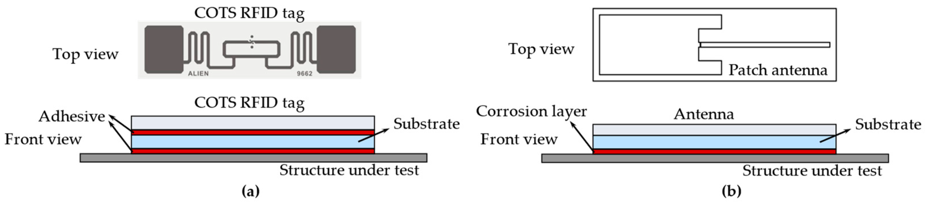
4.1. COTS RFID Tag
4.1.1. Backscatter Power
4.1.2. EMI Shielding Effect
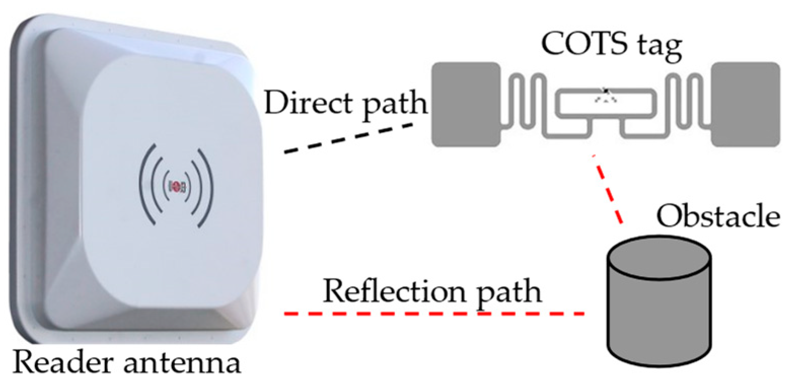
4.1.3. Multi Path Effect
4.1.4. Discussion
4.2. Antenna-Based RFID Sensor Tag
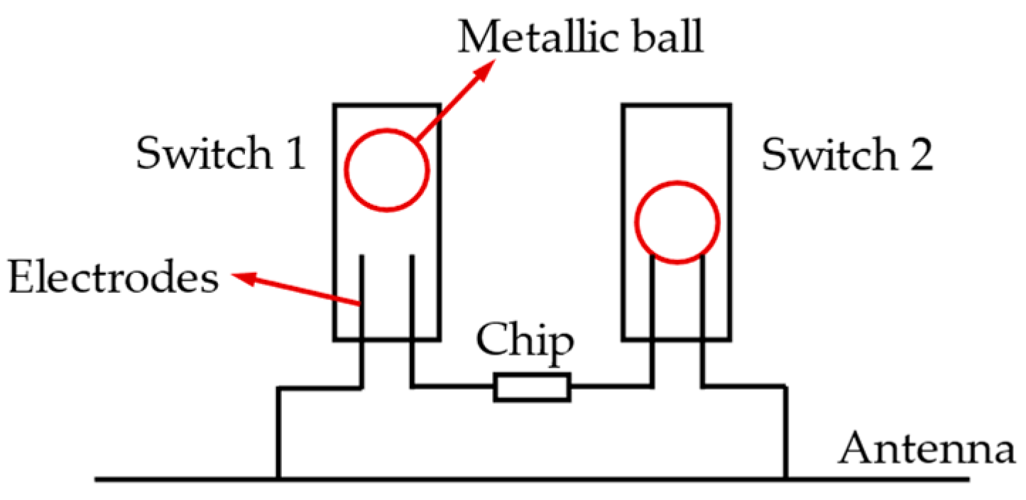
4.2.1. Switches
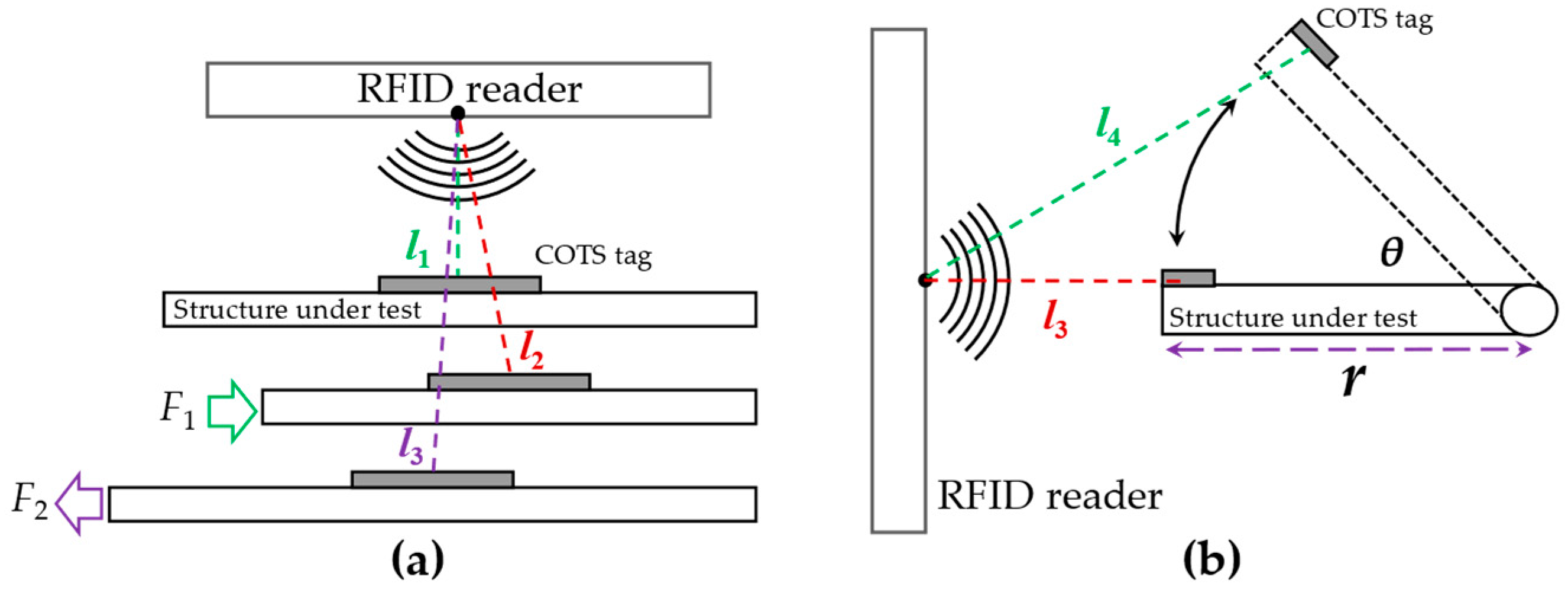
4.2.2. Deformations
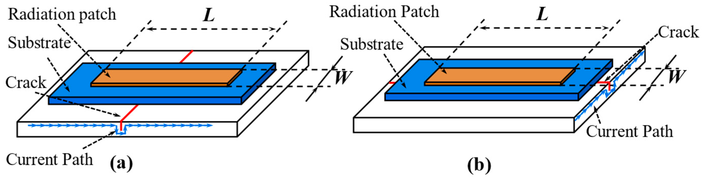
4.2.3. Current Path
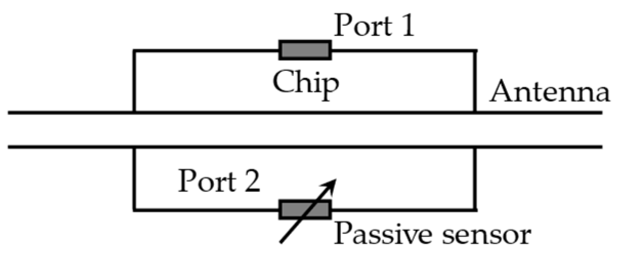
4.2.4. Inter-Antenna Coupling (Coupled Tags)
4.2.5. Discussion
4.3. Digitally Integrated RFID Sensor Tag
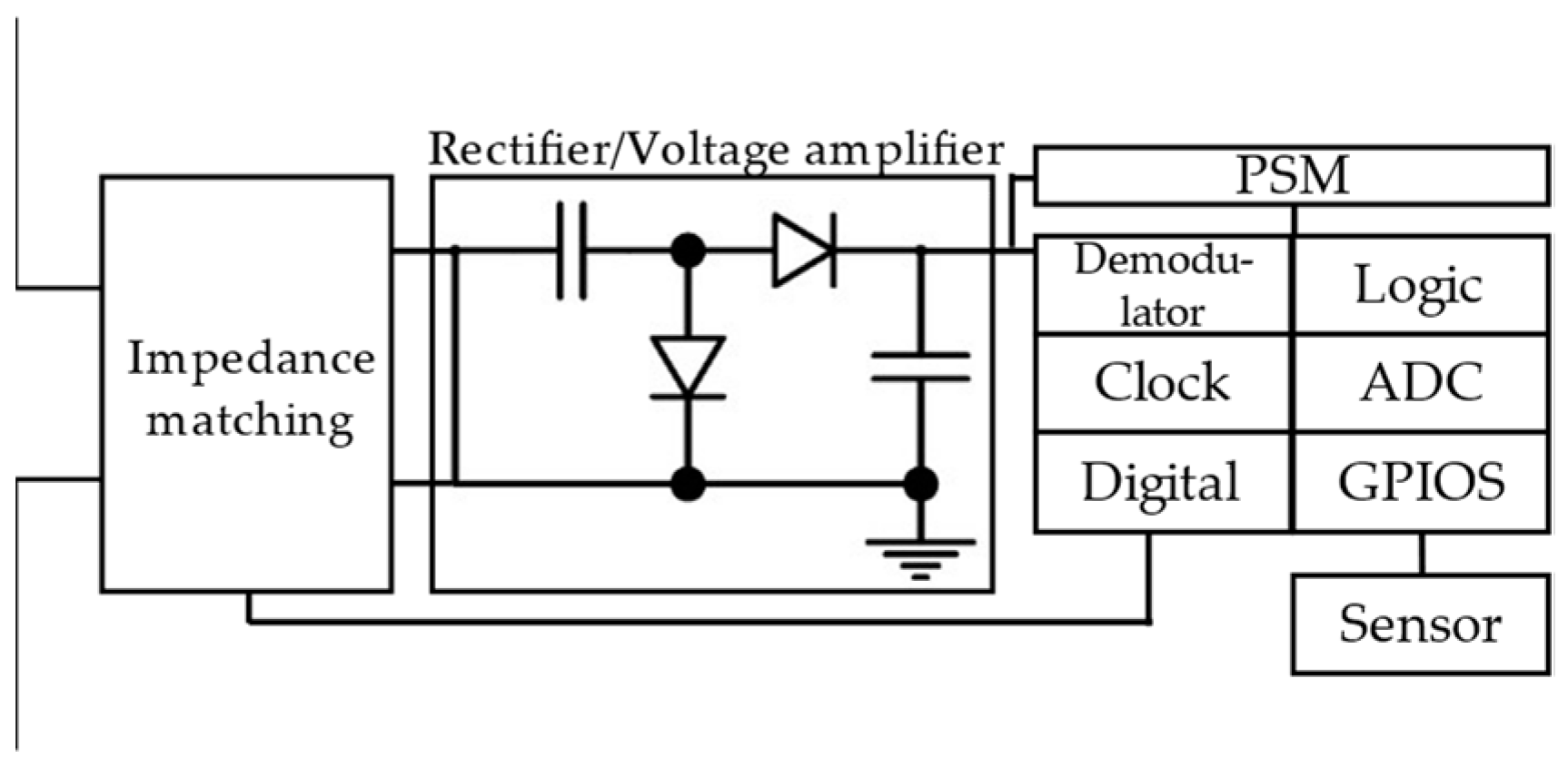
4.3.1. Architecture of Digitally Integrated RFID Sensor Tag
4.3.2. Discussion
4.4. Chipless RFID Sensor Tag
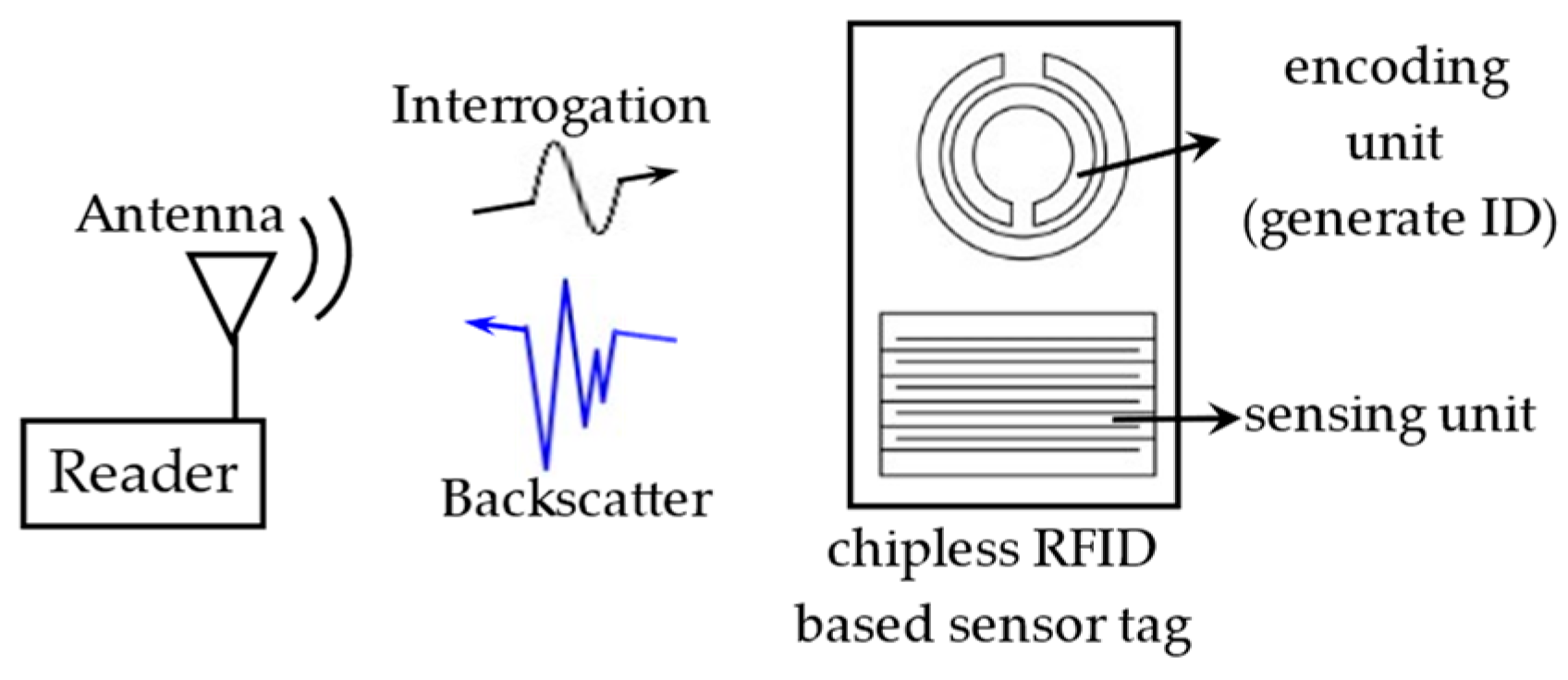
4.4.1. Architecture of Chipless RFID Sensor Tag
4.4.2. Discussion
5. Technical Challenges and Solutions
5.1. Antenna Design
5.1.1. Anti-Metal Performance
5.1.2. Miniaturization
5.2. Multi-Parameters Detection
5.3. Low Sampling Rate of RFID Sensing System
5.4. Communication and Sensing
5.5. Chipless RFID Sensing System
5.6. Printable and Flexible Sensor Tags
5.7. Structural Health Prognostics
6. Conclusions
Author Contributions
Funding
Institutional Review Board Statement
Informed Consent Statement
Data Availability Statement
Conflicts of Interest
References
- Abdulkarem, M.; Samsudin, K.; Rokhani, F.Z.; Rasid, M.F.A. Wireless sensor network for structural health monitoring: A contemporary review of technologies, challenges, and future direction. Struct. Health Monit. 2020, 19, 693–735. [Google Scholar] [CrossRef]
- Dhage, M.R.; Vemuru, S. Structural health monitoring of railway tracks using WSN. In Proceedings of the 2017 International Conference on Computing, Communication, Control and Automation (ICCUBEA), Pune, India, 17–18 August 2017; pp. 1–5. [Google Scholar]
- Mohsen, K.K.; Asedkhan, M.K. Structural health monitoring of oil pipeline using wireless sensor networks. In Proceedings of the 2022 International Congress on Human-Computer Interaction, Optimization and Robotic Applications (HORA), Ankara, Turkey, 9–11 June 2022; pp. 1–5. [Google Scholar]
- Alves, M.M.; Pirmez, L.; Rossetto, S.; Delicato, F.C.; de Farias, C.M.; Pires, P.F.; dos Santos, I.L.; Zomaya, A.Y. Damage prediction for wind turbines using wireless sensor and actuator networks. J. Netw. Comput. Appl. 2017, 80, 123–140. [Google Scholar] [CrossRef]
- Shen, Y.B.; Fu, W.W.; Luo, Y.Z.; Yun, C.B.; Liu, D.; Yang, P.C.; Yang, G.; Zhou, G.G. Implementation of SHM system for Hangzhou East Railway Station using a wireless sensor network. Smart Struct. Syst. 2021, 27, 19–33. [Google Scholar]
- Huang, C.; Huang, B.; Zhang, B.; Li, Y.; Zhang, J.; Wang, K. An Electromagnetically Induced Transparency Inspired Antenna Sensor for Crack Monitoring. IEEE Sens. J. 2021, 21, 651–658. [Google Scholar] [CrossRef]
- Huang, C.; Huang, B.; Zhang, B.; Li, Y.; Zhang, J.; Wang, K. An electromagnetically induced transparency inspired passive wireless sensor for crack monitoring. In Proceedings of the 2019 IEEE MTT-S International Wireless Symposium (IWS), Guangzhou, China, 19–22 May 2019; pp. 1–3. [Google Scholar]
- Chao, W.; Cong, W.; Wan, G.C.; Tong, M.S.; Guan, S.; Xie, L.Y. RFID Antenna Sensor for Quantitatively Monitoring Surface Crack Growth. In Proceedings of the 2019 IEEE International Conference on Computational Electromagnetics (ICCEM), Shanghai, China, 20–22 March 2019; p. 3. [Google Scholar]
- Wang, P.; Dong, L.; Wang, H.; Li, G.; Di, Y.; Xie, X.; Huang, D. Passive Wireless Dual-Tag UHF RFID Sensor System for Surface Crack Monitoring. Sensors 2021, 21, 882. [Google Scholar] [CrossRef] [PubMed]
- DiNatale, A.; DiCarlofelice, A.; DiGiampaolo, E. A Crack Mouth Opening Displacement Gauge Made With Passive UHF RFID Technology. IEEE Sens. J. 2022, 22, 174–181. [Google Scholar] [CrossRef]
- Zhao, A.; Zhang, J.; Tian, G.Y. Miniaturization of UHF RFID Tag Antenna Sensors for Corrosion Characterization. IEEE Sens. J. 2017, 17, 7908–7916. [Google Scholar] [CrossRef]
- Zhang, J.; Tian, G.Y. UHF RFID tag antenna-based sensing for corrosion detection & characterization using principal component analysis. IEEE Trans. Antennas Propag. 2016, 64, 4405–4414. [Google Scholar]
- Soodmand, S.; Zhao, A.; Tian, G.Y. UHF RFID system for wirelessly detection of corrosion based on resonance frequency shift in forward interrogation power. Iet Microw. Antennas Propag. 2018, 12, 1877–1884. [Google Scholar] [CrossRef]
- He, Y.; Li, M.M.; Wan, G.C.; Tong, M.S. A Passive and Wireless Sensor Based on RFID Antenna for Detecting Mechanical Deformation. IEEE Open J. Antennas Propag. 2020, 1, 426–434. [Google Scholar] [CrossRef]
- Li, D.; Wang, Y. Thermally Stable Wireless Patch Antenna Sensor for Strain and Crack Sensing. Sensors 2020, 20, 3835. [Google Scholar] [CrossRef] [PubMed]
- Kuhn, M.F.; Breier, G.P.; Dias, A.R.P.; Clarke, T.G.R. A Novel RFID-Based Strain Sensor for Wireless Structural Health Monitoring. J. Nondestruct. Eval. 2018, 37, 22. [Google Scholar] [CrossRef]
- Chakaravarthi, G.; Logakannan, K.P.; Philip, J.; Rengaswamy, J.; Ramachandran, V.; Arunachalam, K. Reusable Passive Wireless RFID Sensor for Strain Measurement on Metals. IEEE Sens. J. 2018, 18, 5143–5150. [Google Scholar] [CrossRef]
- Zhang, M.; Qiu, J.; Lan, Y.; Wu, J.; Yu, J.; Xu, Z.; Li, E. Detection of Strain Magnitude and Direction Based on an RFID Sensor Array. IEEE Trans. Instrum. Meas. 2022, 71, 8001913. [Google Scholar] [CrossRef]
- Yi, X.; Cho, C.; Cooper, J.; Wang, Y.; Tentzeris, M.M.; Leon, R.T. Passive wireless antenna sensor for strain and crack sensing—Electromagnetic modeling, simulation, and testing. Smart Mater. Struct. 2013, 22, 085009. [Google Scholar] [CrossRef]
- Junjie, Z.; Qiangzhi, F.; Lei, S.; Bian, W. High Sensitivity Stress Sensor Based on Chipless RFID Tag. In Proceedings of the 2021 International Applied Computational Electromagnetics Society (ACES-China) Symposium, Chengdu, China, 28–31 July 2021; p. 2. [Google Scholar]
- Min, S.-H.; Kim, H.-J.; Quan, Y.-J.; Kim, H.-S.; Lyu, J.-H.; Lee, G.-Y.; Ahn, S.-H. Stretchable chipless RFID multi-strain sensors using direct printing of aerosolised nanocomposite. Sens. Actuators A-Phys. 2020, 313, 112224. [Google Scholar] [CrossRef]
- Bruciati, B.; Jang, S.; Fils, P. RFID-Based Crack Detection of Ultra High-Performance Concrete Retrofitted Beams. Sensors 2019, 19, 1573. [Google Scholar] [CrossRef] [Green Version]
- Hao, W.; Qiang, L.; Liang, Z. Research on Passive RFID Tag Antenna Sensor for Metal Structure Strain Detection. In Proceedings of the 2021 Global Reliability and Prognostics and Health Management (PHM-Nanjing), Nanjing, China, 15–17 October 2021; p. 4. [Google Scholar]
- Teng, L.; Pan, K.; Nemitz, M.P.; Song, R.; Hu, Z.; Stokes, A.A. Soft Radio-Frequency Identification Sensors: Wireless Long-Range Strain Sensors Using Radio-Frequency Identification. Soft Robot. 2019, 6, 82–94. [Google Scholar] [CrossRef]
- Song, G.; Zhang, B.; Lyu, Y.; Wang, X.; Wu, B.; He, C.; Lee, Y.-C. Strain omnidirectional detection based on circular patch antenna. Sens. Actuators A Phys. 2020, 315, 112275. [Google Scholar] [CrossRef]
- Wan, G.; Li, M.; Zhang, M.; Kang, L.; Xie, L. A Novel Information Fusion Method of RFID Strain Sensor Based on Microstrip Notch Circuit. IEEE Trans. Instrum. Meas. 2022, 71, 8002610. [Google Scholar] [CrossRef]
- Zhang, J.; Tian, G.Y.; Marindra, A.M.J.; Sunny, A.I.; Zhao, A.B. A Review of Passive RFID Tag Antenna-Based Sensors and Systems for Structural Health Monitoring Applications. Sensors 2017, 17, 265. [Google Scholar] [CrossRef] [PubMed]
- Duan, K.-K.; Cao, S.-Y. Emerging RFID technology in structural engineering—A review. Structures 2020, 28, 2404–2414. [Google Scholar] [CrossRef]
- Deif, S.; Daneshmand, M. Multiresonant Chipless RFID Array System for Coating Defect Detection and Corrosion Prediction. IEEE Trans. Ind. Electron. 2020, 67, 8868–8877. [Google Scholar] [CrossRef]
- Buy RFID System Hardware, Barcoding Equipment & NFC Tracking Solutions Online—Atlas RFID Store. Available online: https://www.atlasrfidstore.com/ (accessed on 20 October 2022).
- Chen, H.; Chen, Y.; Yang, L. Intelligent early structural health prognosis with nonlinear system identification for RFID signal analysis. Comput. Commun. 2020, 157, 150–161. [Google Scholar] [CrossRef]
- Sunny, A.I.; Zhang, J.; Tian, G.Y.; Tang, C.; Rafique, W.; Zhao, A.; Fan, M. Temperature Independent Defect Monitoring Using Passive Wireless RFID Sensing System. IEEE Sens. J. 2019, 19, 1525–1532. [Google Scholar] [CrossRef] [Green Version]
- Rao, K.S.; Nikitin, P.V.; Lam, S.F. Antenna design for UHF RFID tags: A review and a practical application. IEEE Trans. Antennas Propag. 2005, 53, 3870–3876. [Google Scholar] [CrossRef]
- Martinez-Castro, R.E.; Jang, S.; Nicholas, J.; Bansal, R. Experimental assessment of an RFID-based crack sensor for steel structures. Smart Mater. Struct. 2017, 26, 085035. [Google Scholar] [CrossRef]
- Elena Martinez-Castro, R.; Jang, S.; Kim, J.; Wentworth, A. Experimental Evaluation of a Low-Cost RFID-Based Sensor to Crack Propagation. J. Aerosp. Eng. 2019, 32, 04019003. [Google Scholar] [CrossRef]
- Martinez-Castro, R.; Jang, S. Crack Sensor Using Commercial UHF RFID Technology for Metallic Structures. In Proceedings of the Structures Congress—Bridges, Nonbuilding and Special Structures, and Nonstructural Components, Orlando, FL, USA, 24–27 April 2019; pp. 68–77. [Google Scholar]
- Dey, S.; Salim, O.; Masoumi, H.; Karmakar, N.C. A Novel UHF RFID Sensor Based Crack Detection Technique for Coal Mining Conveyor Belt. IEEE J. Radio Freq. Identif. 2022, 6, 19–30. [Google Scholar] [CrossRef]
- Zhao, A.; Sunny, A.I.; Li, L.; Wang, T. Machine Learning-Based Structural Health Monitoring Using RFID for Harsh Environmental Conditions. Electronics 2022, 11, 1740. [Google Scholar] [CrossRef]
- Fils, P.; Jang, S.; Sherpa, R. Field implementation of low-cost RFID-based crack monitoring using machine learning. Struct. Monit. Maint. 2021, 8, 257–278. [Google Scholar]
- Pecho, P.; Hruz, M.; Novak, A.; Trsko, L. Internal Damage Detection of Composite Structures Using Passive RFID Tag Antenna Deformation Method: Basic Research. Sensors 2021, 21, 8236. [Google Scholar] [CrossRef] [PubMed]
- Zohra, F.T.; Salim, O.; Dey, S.; Masoumi, H.; Karmakar, N. A Novel Machine Learning Based Conveyor Belt Health Monitoring Incorporating UHF RFID Backscattered Power. In Proceedings of the 2021 IEEE 5th International Conference on Information Technology, Information Systems and Electrical Engineering (ICITISEE), Purwokerto, Indonesia, 24–25 November 2021; pp. 230–234. [Google Scholar]
- Salim, O.; Dey, S.; Masoumi, H.; Karmakar, N.C. Crack Monitoring System for Soft Rock Mining Conveyor Belt Using UHF RFID Sensors. IEEE Trans. Instrum. Meas. 2021, 70, 1–12. [Google Scholar] [CrossRef]
- Zohra, F.T.; Dey, S.; Salim, O.; Masoumi, H.; Karmakar, N. Design and Analysis of a UHF RFID Crack Sensor for Health Monitoring of Mining Conveyor Belt. In Proceedings of the 2020 27th International Conference on Telecommunications (ICT), Bali, Indonesia, 5–7 October 2020; p. 5. [Google Scholar]
- El Masri, I.; Lescop, B.; Talbot, P.; Nguyen Vien, G.; Becker, J.; Thierry, D.; Rioual, S. Development of a RFID sensitive tag dedicated to the monitoring of the environmental corrosiveness for indoor applications. Sens. Actuators B-Chem. 2020, 322, 128602. [Google Scholar] [CrossRef]
- Zhang, J.; Tian, G.Y.; Zhao, A.B. Passive RFID sensor systems for crack detection & characterization. Ndt E Int. 2017, 86, 89–99. [Google Scholar]
- Soodmand, S.; Tian, G.Y. Comments on “UHF RFID Tag Antenna-Based Sensing for Corrosion Detection and Characterization Using Principal Component Analysis”. IEEE Trans. Antennas Propag. 2018, 66, 6465. [Google Scholar] [CrossRef]
- He, Y. Wireless Corrosion Monitoring Sensors Based on Electromagnetic Interference Shielding of RFID Transponders. Corrosion 2020, 76, 411–423. [Google Scholar] [CrossRef] [Green Version]
- He, Y.; McLaughlin, S.; Lo, J.S.; Shi, C.; Lenos, J.; Vincelli, A. Radio frequency identification (RFID) based corrosion monitoring sensors Part 2–Application and testing of coating materials. Corros. Eng. Sci. Technol. 2014, 49, 695–704. [Google Scholar] [CrossRef]
- He, Y.; McLaughlin, S.; Lo, J.; Shi, C.; Lenos, J.; Vincelli, A. Radio frequency identification (RFID) based corrosion monitoring sensors Part 1–Component selection and testing. Corros. Eng. Sci. Technol. 2015, 50, 63–71. [Google Scholar] [CrossRef]
- Dante, J.F.; Friedersdorf, F.; Innovations, L. Low-cost wireless corrosivity sensors. In Proceedings of the 2007 Tri-Service Corrosion Conference, Denver, CO, USA, 11–15 March 2007. [Google Scholar]
- Yang, L.; Li, Y.; Lin, Q.; Jia, H.; Li, X.-Y.; Liu, Y. Tagbeat: Sensing mechanical vibration period with cots rfid systems. IEEE/ACM Trans. Netw. 2017, 25, 3823–3835. [Google Scholar] [CrossRef]
- Yang, P.; Feng, Y.; Xiong, J.; Chen, Z.; Li, X.-Y. RF-Ear: Contactless Multi-device Vibration Sensing and Identification Using COTS RFID. In Proceedings of the 39th IEEE International Conference on Computer Communications (IEEE INFOCOM), Electr Network, Toronto, ON, Canada, 6–9 July 2020; pp. 297–306. [Google Scholar]
- Binbin, X.; Jie, X.; Xiaojiang, C.; Dingyi, F. Exploring commodity RFID for contactless sub-millimeter vibration sensing. In Proceedings of the 18th Conference on Embedded Networked Sensor Systems, Virtual Event, Japan, 16–19 November 2020; pp. 15–27. [Google Scholar]
- Feng, Y.; Yang, P.; Zhang, Y.; Li, X.-Y.; Chen, Z.; Huang, G. Demo: The RFID Can Hear Your Music Play. In Proceedings of the 25th Annual International Conference on Mobile Computing and Networking (MobiCom), Los Cabos, Mexico, 21–25 October 2019. [Google Scholar]
- Feng, Y.; Chen, Z.; Huang, G.; Yan, Y.; Li, X.-Y.; Yang, P. RF-Recorder: A Contactless Music Play Recording System Using COTS RFID. In Proceedings of the 15th International Conference on Mobile Ad-Hoc and Sensor Networks (MSN), Shenzhen, China, 11–13 December 2019; pp. 37–42. [Google Scholar]
- Zhu, B.; Tian, L.; Wu, D.; Dong, M.; Gao, S.; Zhang, L.; Liu, S.; Li, D.-A.; Soc, I.C. RF-Vsensing: RFID-based Single Tag Contactless Vibration Sensing and Recognition. In Proceedings of the 17th IEEE International Conference on Mobility, Sensing and Networking (MSN), Exeter, UK, 13–15 December 2021; pp. 438–445. [Google Scholar]
- Li, P.; An, Z.; Yang, L.; Yang, P. Towards Physical-Layer Vibration Sensing with RFIDs. In Proceedings of the IEEE Conference on Computer Communications (IEEE INFOCOM), Paris, France, 29 April–2 May 2019; pp. 892–900. [Google Scholar]
- Su, D.; Tian, G.; Gao, B.; Zhang, J. UHF RFID Sensor Array for Bending stress assessment. In Proceedings of the IEEE Far East NDT New Technology and Application Forum (IEEE FENDT), Qingdao, China, 24–27 June 2019; pp. 120–124. [Google Scholar]
- Omer, M.; Tian, G.Y.; Gao, B.; Su, D. Passive UHF RFID Tag as a Sensor for Crack Depths. IEEE Sens. J. 2018, 18, 9867–9873. [Google Scholar] [CrossRef] [Green Version]
- Zhang, H.; Yang, R.; He, Y.; Wu, R. Characterisation of steel corrosion using high frequency RFID. In Proceedings of the IEEE Far East Forum on Nondestructive Evaluation/Testing–New Technology and Application (IEEE FENDT), Xi’an, China, 22–24 June 2017; pp. 127–132. [Google Scholar]
- Li, P.; An, Z.; Yang, L.; Yang, P.; Lin, Q. RFID Harmonic for Vibration Sensing. IEEE Trans. Mob. Comput. 2021, 20, 1614–1626. [Google Scholar] [CrossRef]
- Rahmadya, B.; Chen, X.; Takeda, S.; Kagoshima, K.; Umehira, M.; Kurosaki, W. Measurement of a UHF RFID-Based Battery-Less Vibration Frequency Sensitive Sensor Tag Using Tilt/Vibration Switches. IEEE Sens. J. 2020, 20, 9901–9909. [Google Scholar] [CrossRef]
- Dongfang, F.; Higuchi, T.; Kobayashi, Y.; Takeda, S.; Kagoshima, K.; Umehira, M. Measurement of a novel UHF RFID based battery-less vibration frequency sensing tag. In Proceedings of the 2018 International Symposium on Antennas and Propagation (ISAP), Busan, Korea, 23–26 October 2018; p. 2. [Google Scholar]
- Song, Z.; Sun, R.; Rahmadya, B.; Takeda, S. A Battery-Less RFID-Based Wireless Vibration and Physical-Shock Sensing System Using Edge Processing for Long-Term Measurements. In Proceedings of the 31st International Telecommunication Networks and Applications Conference (ITNAC), Univ New S Wales, Sydney, Australia, 24–26 November 2021; pp. 104–106. [Google Scholar]
- Tata, U.S. Study of Patch Antennas for Strain Measurement; IOS Press: Amsterdam, The Netherlands, 2008. [Google Scholar]
- Yi, X.; Cho, C.; Wang, Y.; Tentzeris, M.M. Battery-free slotted patch antenna sensor for wireless strain and crack monitoring. Smart Struct. Syst 2016, 18, 1217–1231. [Google Scholar] [CrossRef]
- Kangqian, X.; Liyue, X.; Songtao, X.; Ke, X.; Guochun, W. Influence of transverse deformation on resonant frequency of patch antenna. In Proceedings of the 2018 IEEE Sensors Applications Symposium (SAS), Seoul, Korea, 12–14 March 2018; p. 6. [Google Scholar]
- Xu, Y.; Dong, L.; Wang, H.; Xie, X.; Wang, P. Surface crack detection and monitoring in metal structure using RFID tag. Sens. Rev. 2020, 40, 81–88. [Google Scholar] [CrossRef]
- Xu, Y.; Dong, L.; Wang, H.; Di, Y.; Xie, X.; Wang, P.; Zhang, M. Reducing disturbance of crack location on crack depth-sensing tag. Sens. Rev. 2019, 39, 449–455. [Google Scholar] [CrossRef]
- Wang, P.; Dong, L.; Wang, H.; Li, G.; Di, Y.; Xie, X.; Huang, D. Investigation the influence of miniaturized RFID tag sensor on coupling effect. Sens. Rev. 2021, 41, 425–435. [Google Scholar] [CrossRef]
- Wang, P.; Dong, L.; Wang, H.; Li, G.; Xie, X. Passive Ultra High Frequency RFID sensor with reference tag for crack detection of aluminum alloy structure. J. Instrum. 2021, 16, P11018. [Google Scholar] [CrossRef]
- Caizzone, S.; DiGiampaolo, E.; Marrocco, G. Constrained pole-zero synthesis of phase-oriented RFID sensor antennas. IEEE Trans. Antennas Propag. 2015, 64, 496–503. [Google Scholar] [CrossRef]
- Caizzone, S.; DiGiampaolo, E. Wireless passive RFID crack width sensor for structural health monitoring. IEEE Sens. J. 2015, 15, 6767–6774. [Google Scholar] [CrossRef] [Green Version]
- Caizzone, S.; DiGiampaolo, E.; Marrocco, G. Wireless crack monitoring by stationary phase measurements from coupled RFID tags. IEEE Trans. Antennas Propag. 2014, 62, 6412–6419. [Google Scholar] [CrossRef] [Green Version]
- Sample, A.P.; Yeager, D.J.; Powledge, P.S.; Mamishev, A.V.; Smith, J.R. Design of an RFID-Based Battery-Free Programmable Sensing Platform. IEEE Trans. Instrum. Meas. 2008, 57, 2608–2615. [Google Scholar] [CrossRef]
- Sample, A.P.; Smith, J.R. The wireless identification and sensing platform. In Wirelessly Powered Sensor Networks and Computational RFID; Springer: Berlin/Heidelberg, Germany, 2013; pp. 33–56. [Google Scholar]
- Li, P.; Long, Z.; Yang, Z. RF Energy Harvesting for Batteryless and Maintenance-Free Condition Monitoring of Railway Tracks. IEEE Internet Things J. 2021, 8, 3512–3523. [Google Scholar] [CrossRef]
- Rennane, A.; Benmahmoud, F.; Abdelnour, A.; Fonseca, N.; Kaddour, D.; Touhami, R.; Tedjini, S. Passive UHF RFID Bending and Absolute Force Strain Gauge Based Sensors. In Proceedings of the Mediterranean Microwave Symposium (MMS), Marseille, France, 28–30 November 2017. [Google Scholar]
- DiGiampaolo, E.; DiCarlofelice, A.; Gregori, A. An RFID-Enabled Wireless Strain Gauge Sensor for Static and Dynamic Structural Monitoring. IEEE Sens. J. 2017, 17, 286–294. [Google Scholar] [CrossRef]
- Gregori, A.; Di Giampaolo, E.; Di Carlofelice, A.; Castoro, C. Presenting a New Wireless Strain Method for Structural Monitoring: Experimental Validation. J. Sens. 2019, 2019, 5370838. [Google Scholar] [CrossRef] [Green Version]
- Jayawardana, D.; Liyanapathirana, R.; Zhu, X. RFID-Based Wireless Multi-Sensory System for Simultaneous Dynamic Acceleration and Strain Measurements of Civil Infrastructure. IEEE Sens. J. 2019, 19, 12389–12397. [Google Scholar] [CrossRef]
- Ximeng, C.; Yating, Y.; Lei, W.; Cheng, S.; Guiyun, T. Wireless stress measurement on metal surface based on passive integrated RFID sensor tag. In Proceedings of the 2021 IEEE International Instrumentation and Measurement Technology Conference (I2MTC), Glasgow, UK, 17–20 May 2021; p. 6. [Google Scholar]
- Wang, T.; He, Y.; Shi, T.; Li, B. Transformer Incipient Hybrid Fault Diagnosis Based on Solar-Powered RFID Sensor and Optimized DBN Approach. IEEE Access 2019, 7, 74103–74110. [Google Scholar] [CrossRef]
- Zhang, C.; He, Y.; Jiang, S.; Wang, T.; Yuan, L.; Li, B. Transformer Fault Diagnosis Method Based on Self-Powered RFID Sensor Tag, DBN, and MKSVM. IEEE Sens. J. 2019, 19, 8202–8214. [Google Scholar] [CrossRef]
- Wang, T.; He, Y.; Li, B.; Shi, T. Transformer Fault Diagnosis Using Self-Powered RFID Sensor and Deep Learning Approach. IEEE Sens. J. 2018, 18, 6399–6411. [Google Scholar] [CrossRef]
- Wang, T.; He, Y.; Luo, Q.; Deng, F.; Zhang, C. Self-Powered RFID Sensor Tag for Fault Diagnosis and Prognosis of Transformer Winding. IEEE Sens. J. 2017, 17, 6418–6430. [Google Scholar] [CrossRef]
- Lu, L.; He, Y.; Ruan, Y.; Yuan, W. Wind Turbine Planetary Gearbox Condition Monitoring Method Based on Wireless Sensor and Deep Learning Approach. IEEE Trans. Instrum. Meas. 2021, 70, 3503016. [Google Scholar] [CrossRef]
- Mutlu, F.; Demir, M.A.; Ergul, O. Improved Fonts for Chipless Radio-Frequency-Identification Tags Based on Letters. In Proceedings of the 2018 18th Mediterranean Microwave Symposium (MMS), Istanbul, Turkey, 31 October 2018–2 November 2018; pp. 247–250. [Google Scholar]
- Pereira, F.; Correia, R.; Jordao, M.; Carvalho, N.B. Chipless Strain Sensor using Phase Modulation. In Proceedings of the IEEE Wireless Power Transfer Conference (WPTC), Electr Network, Seoul, Korea, 15–19 November 2020; pp. 420–423. [Google Scholar]
- Ni, Y.z.; Huang, X.d.; Lv, Y.p.; Cheng, C.h. Hybrid coding chipless tag based on impedance loading. IET Microw. Antennas Propag. 2017, 11, 1325–1331. [Google Scholar] [CrossRef]
- Kumar, C.S.; Patre, S.R. Compass-shaped RFID Sensor Tag for Metal Crack Detection. In Proceedings of the 2021 2nd International Conference for Emerging Technology (INCET), Belagavi, India, 21–23 May 2021; p. 4. [Google Scholar]
- Javed, N.; Azam, M.A.; Amin, Y. Chipless RFID Multisensor for Temperature Sensing and Crack Monitoring in an IoT Environment. IEEE Sens. Lett. 2021, 5, 6001404. [Google Scholar] [CrossRef]
- Mc Gee, K.; Anandarajah, P.; Collins, D. Proof of Concept Novel Configurable Chipless RFID Strain Sensor. Sensors 2021, 21, 6224. [Google Scholar] [CrossRef]
- Mengue, P.; Paulmier, B.; Hage-Ali, S.; Floer, C.; M’Jahed, H.; Shvetsov, A.; Zhgoon, S.; Elmazria, O. SAW-RFID temperature and strain sensors on metallic substrates. In Proceedings of the 20th IEEE Sensors Conference, Electr Network, 31 October–4 November 2021. [Google Scholar]
- Marindra, A.M.J.; Sutthaweekul, R.; Tian, G.Y. Depolarizing Chipless RFID Sensor Tag for Characterization of Metal Cracks Based on Dual Resonance Features. In Proceedings of the 10th Annual International Conference on Information Technology and Electrical Engineering (ICITEE), Kuta, Indonesia, 24–26 July 2018; pp. 73–78. [Google Scholar]
- Dey, S.; Kalansuriya, P.; Karmakar, N.C. Novel Chipless RFID High Resolution Crack Sensor Based on SWB Technology. IEEE Sens. J. 2021, 21, 2908–2920. [Google Scholar] [CrossRef]
- Dey, S.; Amin, E.M.; Karmakar, N.C. Paper based chipless RFID leaf wetness detector for plant health monitoring. IEEE Access 2020, 8, 191986–191996. [Google Scholar] [CrossRef]
- Wan, G.; Kang, W.; Wang, C.; Li, W.; Li, M.; Xie, L.; Chen, L. Separating strain sensor based on dual-resonant circular patch antenna with chipless RFID tag. Smart Mater. Struct. 2021, 30, 015007. [Google Scholar] [CrossRef]
- Marindra, A.M.J.; Tian, G.Y. Chipless RFID Sensor Tag for Metal Crack Detection and Characterization. IEEE Trans. Microw. Theory Tech. 2018, 66, 2452–2462. [Google Scholar] [CrossRef]
- Marindra, A.M.J.; Tian, G.Y. Chipless RFID sensor for corrosion characterization based on frequency selective surface and feature fusion. Smart Mater. Struct. 2020, 29, 125010. [Google Scholar] [CrossRef]
- Caldero, P.; Zoeke, D. Multi-Channel Real-Time Condition Monitoring System Based on Wideband Vibration Analysis of Motor Shafts Using SAW RFID Tags Coupled with Sensors. Sensors 2019, 19, 5398. [Google Scholar] [CrossRef]
- Caldero, P.; Zoeke, D. Real-Time Wireless Vibration Monitoring Using SAW RFID Tags Coupled with Sensors. In Proceedings of the 15th European Radar Conference (EuRAD), Madrid, Spain, 26–28 September 2018; pp. 118–121. [Google Scholar]
- Tata, U.; Huang, H.; Carter, R.; Chiao, J. Exploiting a patch antenna for strain measurements. Meas. Sci. Technol. 2008, 20, 015201. [Google Scholar] [CrossRef]
- Mohammad, I.; Huang, H. Shear sensing based on a microstrip patch antenna. Meas. Sci. Technol. 2012, 23, 105705. [Google Scholar] [CrossRef]
- Wan, G.C.; Li, M.M.; Yang, Y.L.; Xie, L.; Chen, L. Patch-Antenna-Based Structural Strain Measurement Using Optimized Energy Detection Algorithm Applied on USRP. IEEE Internet Things J. 2021, 8, 7476–7484. [Google Scholar] [CrossRef]
- Zhiping, L.; Runfa, L.; Jianming, Y.; Hanjin, Y. Research on weld surface notch monitoring based on microstrip antenna sensor array. Meas. Sci. Technol. 2019, 31, 035102. [Google Scholar] [CrossRef]
- Daliri, A.; Galehdar, A.; Rowe, W.S.; Ghorbani, K.; John, S. Utilising microstrip patch antenna strain sensors for structural health monitoring. J. Intell. Mater. Syst. Struct. 2012, 23, 169–182. [Google Scholar] [CrossRef]
- Chompoosawat, W.; Boonpoonga, A.; Akkaraekthalin, P.; Bannawat, L.; Lertwiriyaprapa, T. Single-layer Chipless RFID Sensor for Metal Crack Detection. In Proceedings of the 2021 9th International Electrical Engineering Congress (iEECON), Pattaya, Thailand, 10–12 March 2021; pp. 575–578. [Google Scholar]
- Kumar, C.S.; Patre, S.R. Array of chipless RFID sensor tag for wireless detection of crack on large metallic surface. In Proceedings of the IEEE International Conference on RFID Technology and Applications (IEEE RFID-TA), Delhi, India, 6–8 October 2021; pp. 142–144. [Google Scholar]
- Clementi, G.; Fortino, N.; Dauvignac, J.-Y. A novel low profile Tapered Slot Antenna with absorbing material for radar imaging system. In Proceedings of the 2013 7th European Conference on Antennas and Propagation (EuCAP), Gothenburg, Sweden, 8–12 April 2013; pp. 2891–2895. [Google Scholar]
- Gao, B.; Yuen, M.M. Passive UHF RFID packaging with electromagnetic band gap (EBG) material for metallic objects tracking. IEEE Trans. Compon. Packag. Manuf. Technol. 2011, 1, 1140–1146. [Google Scholar] [CrossRef]
- Fallahpour, M.; Zoughi, R. Antenna miniaturization techniques: A review of topology-and material-based methods. IEEE Antennas Propag. Mag. 2017, 60, 38–50. [Google Scholar] [CrossRef]
- Wan, G.C.; Li, M.M.; Wang, C.; Tong, M.S.; Xie, L. Simulation Analysis of Dual Band Microstrip Antenna Strain Sensor Based on RFID. In Proceedings of the 2019 IEEE International Conference on Computational Electromagnetics (ICCEM), Shanghai, China, 20–22 March 2019. [Google Scholar]
- Wang, T.; Dai, S.; Liu, Y.; Ye, T.T. Battery-Less Sensing of Body Movements Through Differential Backscattered RFID Signals. IEEE Sens. J. 2022, 22, 8490–8498. [Google Scholar] [CrossRef]
- Sievenpiper, D.F.; Dawson, D.C.; Jacob, M.M.; Kanar, T.; Kim, S.; Long, J.; Quarfoth, R.G. Experimental validation of performance limits and design guidelines for small antennas. IEEE Trans. Antennas Propag. 2011, 60, 8–19. [Google Scholar] [CrossRef]
- El Khamlichi, M.; Alvarez Melcon, A.; El Mrabet, O.; Ennasar, M.A.; Hinojosa, J. Flexible UHF RFID tag for blood tubes monitoring. Sensors 2019, 19, 4903. [Google Scholar] [CrossRef] [Green Version]
- Zhang, J.; Huang, H.; Huang, C.; Zhang, B.; Li, Y.; Wang, K.; Su, D.; Tian, G.Y. A configurable dielectric resonator-based passive wireless sensor for crack monitoring. IEEE Trans. Antennas Propag. 2019, 67, 5746–5749. [Google Scholar] [CrossRef]
- Tang, L.Y.; Xia, Z.W.; Wan, G.C.; Tong, M.S. A Dynamic Detection Method for RFID Strain Sensor Tag Antenna Based on USRP X300. In Proceedings of the Progress in Electromagnetics Research Symposium (PIERS-Toyama), Toyama, Japan, 1–4 August 2018; pp. 2061–2065. [Google Scholar]
- Zhang, M.X.; Wan, G.C.; Tong, M.S. A Spectrum Sensing Scheme Based on Second-order Variable Step Energy Detection for Detecting 3bit Passive Wireless RFID Tag Antenna. In Proceedings of the Photonics and Electromagnetics Research Symposium—Fall (PIERS—Fall), Xiamen, China, 17–20 December 2019; pp. 1685–1690. [Google Scholar]
- Khaliel, M.; El-Awamry, A.; Fawky, A.; Kaiser, T. Long reading range for the frequency coded Chipless RFID system based on reflectarray antennas. Int. J. Microw. Wirel. Technol. 2018, 10, 187–195. [Google Scholar] [CrossRef] [Green Version]
- Nappi, S.; Marrocco, G. Inkjet-Printed RFID-Skins for the Detection of Surface Defects. In Proceedings of the 2018 2nd URSI Atlantic Radio Science Meeting (AT-RASC), Gran Canaria, Spain, 28 May–1 June 2018; p. 4. [Google Scholar]
- Nappi, S.; Gargale, L.; Valentini, P.P.; Marrocco, G. RF Detection of Micro-cracks in Orthopedic Implants by Conformal Space Filling Curves. In Proceedings of the IEEE International Conference on RFID Technology and Applications (RFID-TA), Pisa, Italy, 25–27 September 2019. [Google Scholar]
- Nappi, S.; Marrocco, G. Space-Filling Electromagnetic Skins for the Wireless Monitoring of Surface Defects. IEEE Sens. J. 2019, 19, 11535–11543. [Google Scholar] [CrossRef]
- Nappi, S.; Valentini, P.P.; Marrocco, G. Conformal space-filling electromagnetic skins for the wireless monitoring of 3D object integrity. In Proceedings of the 2019 13th Eur. Conf. Antennas Propag. (EuCAP), Krakow, Poland, 31 March 2019–05 April 2019; p. 4. [Google Scholar]
- Nappi, S.; Gargale, L.; Naccarata, F.; Valentini, P.P.; Marrocco, G. A Fractal-RFID Based Sensing Tattoo for the Early Detection of Cracks in Implanted Metal Prostheses. IEEE J. Electromagn. Rf Microw. Med. Biol. 2022, 6, 29–40. [Google Scholar] [CrossRef]
- Wang, Z.; Yang, X.; Zhou, X.; Su, P.; Wang, J. A Flexible Sensor Tag for Surface Crack Detection of Curved Film-Coated Metals. IEEE Sens. J. 2022, 22, 5662–5668. [Google Scholar] [CrossRef]
- Rizwan, M.; Khan, M.W.A.; He, H.; Virkki, J.; Sydanheimo, L.; Ukkonen, L. Flexible and stretchable 3D printed passive UHF RFID tag. Electron. Lett. 2017, 53, 1054–1055. [Google Scholar] [CrossRef]
- Khan, S.; Yairi, T. A review on the application of deep learning in system health management. Mech. Syst. Signal Process. 2018, 107, 241–265. [Google Scholar] [CrossRef]
- Zhou, F.; Gao, Y.; Wen, C. A novel multimode fault classification method based on deep learning. J. Control Sci. Eng. 2017, 2017, 3583610. [Google Scholar] [CrossRef]


| Database | Web of Science |
|---|---|
| Topic for retrieval | (radio frequency identification or RFID) and (sensing or sensor) and (structural health monitoring or SHM) |
| Publication years | 2017–2022 |
| Document types | exclude patents |
| Categories for refinement | strain or stress, crack or corrosion, and vibration in SHM |
| Frequency Band | LF (30~300 kHz) | HF (3~30 MHz) | UHF (300~3000 MHz) | |
|---|---|---|---|---|
| Primary frequency | 125~134 kHz | 13.56 MHz | 433 MHz; 860~960 MHz; 2.45 GHz | |
| Power source | passive (RF energy) | passive (RF energy) | passive (RF energy) | semi-passive/battery |
| Read Range | shorter than 10 cm | shorter than 30 cm | shorter than 25 m | longer than 30 m |
| Applications | animal tracking, access control; car key-fob; application with high-density liquids and metals | identification (ID) cards; near-field communication (NFC) application; library books | supply chain tracking; manufacturing; pharmaceuticals; electronic tolling; inventory tracking; race timing; asset tracking | vehicle tracking; auto manufacturing, mining; construction, asset tracking |
| Pros | high performance near water and metal; global standards | larger memory options, global standards; NFC global protocols | long read range; low cost per tag; wide variety of tag sizes and shapes; global standards; high data transmission rates | very long read range; lower infrastructure cost (vs. passive RFID), large memory capacity; high data transmission rates |
| Cons | low data rate; short read range; limited quantity of memory | low data rate; short read range | high equipment costs; moderate memory capacity; high interference from metal and liquids | shipping restrictions (due to batteries); complex software may be required; high interference from metal and liquids; few global standards |
| Tag | Sensing Parameters | Sensing Variables | Sensitivity | Application Notes | Ref. |
|---|---|---|---|---|---|
| IMPINJ H47 tags | bending stress assessment | active power | n/a |
| [58] |
| Alien Technology ALN-9662 short Inlay tag | steel structures crack | RSSI | n/a |
| [34,35,36] |
| various COTS tags | slot cracks of carbon steel and stainless steel | power/phase, machine learning | accuracy of crack feature extraction: 84.4% in width and 78.7% in depth. |
| [38] |
| commercial tag (n/a) | crack depth | RSSI | n/a |
| [59] |
| Texas instrument HF tag (RF-HDT-DVBB-N2-TAG) | corrosion time | transient response | n/a |
| [60] |
| ALN-9654 from Alien technologies with a Higgs-3 chip | corrosion | RSSI | 0.4 dB/mm |
| [44] |
| commercial RFID tags | corrosion | RSSI/threshold transmitted power | n/a |
| [47] |
| AZ9662 H3 commercial RFID tags | composite structures internal damage detection | n/a | n/a |
| [40] |
| Alien technology ALN-9662 short Inlay tag | concrete cracks | RSSI | n/a |
| [22,39] |
| Alien tags | vibration | backscatter power | vibration period relative error of 0.03% and mean accuracy of 0.36 ms |
| [51] |
| commercial tags | vibration | phase | frequency up to 400 Hz with a mean error of 0.2% |
| [52,54,55] |
| COTS RFID tags (ImpinJ and Alien) | vibration | base band signal | mean error: 0.37 Hz (<100 Hz); mean error: 4.2 Hz (~2500 Hz) |
| [57,61] |
| COTS tags | vibration | phase | vibration amplitude: 0.5 mm |
| [53] |
| Tag Design | Sensing Parameters | Sensing Variables | Sensitivity | Application Notes | Ref. |
|---|---|---|---|---|---|
| the microstrip antenna and FR4 substrate | strain of metal structures | phase | mean phased difference about 12°/2 cm |
| [23] |
| planar inverted-F antenna and CTC13001 chip on N9220 substrate | strain of aluminum sheet | reading range | 550 Hz/με |
| [16] |
| meandered dipole antenna and Higgs-4 chip on RO4350 substrate | strain measurement on metals | RSSI | n/a |
| [17] |
| short stub feed patch antenna on FR4 substrate | strain of metal structures | s-parameters | horizontal strain: −873.91 Hz/με; vertical strain: 57.28 Hz/με |
| [18] |
| folded-patch antenna and SL3S1013 chip on RT/duroid 6202 substrate | strain and crack sensing | interrogation power | −599 Hz/με |
| [15] |
| 3D-antenna | crack depth and corrosion progression | backscatter power/phase | n/a |
| [12,45,46] |
| electromagnetically induced transparency inspired antenna | slot crack depth and width | turn on power | crack depth: 2.73 MHz/mm2; crack width: 2.75 MHz/mm2 |
| [6,7] |
| rectangular patch antenna on FR4 substrate | crack depth and length | read threshold transmitted power | n/a |
| [9,68,69,70,71] |
| T-shape folded antenna and Monza-4 chip | corrosion exposed time | threshold power | 45 kHz/μm |
| [11] |
| two-port UHF RFID tag | crack opening displacement | phase | Phase shift: 16 °/mm. Maximum measurement range: 5 mm |
| [10] |
| antenna, tilt/vibration sensors, and RFID chip | vibration | read interval or read rate | n/a |
| [62,63,64] |
| Tag Design | Sensor | Energy Source | Reading Distance | Performance | Ref. |
|---|---|---|---|---|---|
| Rocky100 RFID chip and MSP430FR2433 | semiconductor strain transducer | RF energy | 60 cm. (ImpinJ R420 reader, Seattle, WA, USA) |
| [82] |
| SL900A tag | strain gauges | RF energy | n/a |
| [78] |
| commercial NXP G2iL chip-based tag | strain gauges | RF energy or battery assisted | longer than 20 m |
| [79,80] |
| ImpinJ Monza-X chip-based tag | strain gauges and acceleration sensor | RF energy and battery | 1.5 m |
| [81] |
| Monza X-8K RFID unit | ADXL372/ADXL345 accelerometer sensor | solar power/RF energy | up to 17 m |
| [83,84,85,86] |
| nRF24L01 | ADXL345 accelerometer sensor | piezoelectric energy harvester/vibration energy | 13 m |
| [87] |
| CC430F5137 wireless transceiver | ADXL362 accelerometer | RF energy | 2.3 m |
| [77] |
| Encoding Methods | Principle | Pros | Cons |
|---|---|---|---|
| shape-based | the electromagnetic (EM) signature of a specific shape | simple | low coding density |
| time domain | the duration and interval of the reflected signal | long reading distance; low energy demand | coding capacity and coding density are small; high requirement for readers |
| frequency domain | encoding data into spectrum using different resonant structures | large storge potentials; high coding density | large spectrum and wideband dedicated reader required |
| amplitude/phase domain | phase or amplitude modulation of the RCS can be achieved by changing the impedance of the tag antenna | occupy small spectrum resources; simple structure | small coding capacity; additional components required |
| hybrid | using more than one domain in coding | the data capacity can be greatly increased | complex design |
| Tag Design | Sensing Parameters | Sensing Variables | Sensitivity | Application Notes | Ref. |
|---|---|---|---|---|---|
| circular patch antenna on RT/duroid 5880 substrate | strain | S-parameters | 0°: −1.218 kHz/με; 15°: −1.064 kHz/με; 30°: −0.881 kHz/με; 45°: −0.375 kHz/με; 60°: −0.054 kHz/με; 75°: 0.068 kHz/με; 90°: 0.415 kHz/με |
| [25] |
| rectangular loop with finger capacitor on flexible polydimethylsiloxane (PDMS) substrate | strain | RCS | n/a |
| [21] |
| dual-resonant CMPA on RT/duroid 5880 substrate | strain | RCS | horizontal strain: 528 Hz/με; vertical strain: 384 Hz/με |
| [98] |
| CMPA and tip loaded dipoles on Taconic CER-10-0500 laminate | crack | RCS | horizontal crack: 13.43 MHz/0.1 mm; vertical crack: 6.67 MHz/0.1 mm |
| [99] |
| CMPA and six inverted “U” and “L” shaped resonators on Rogers RT/duroid 5880 | temperature and crack width | RCS | −58.8 MHz/0.1 mm |
| [92] |
| frequency selective surface | the increase of corrosion layer thickness | S-parameters | 17.6 MHz/month; 1.34 MHz/μm |
| [100] |
| surface acoustic wave RFID tag with modulator circuit | vibration | time domain signals | n/a |
| [101,102] |
| For frequency = start 902: step 0.5: end 928MHz. |
| For power = start 5: step 0.5: end 30dBm. |
| Query: reader sent request. |
| If tag respond: |
| Save the received data. |
| End if. |
| End Query. |
| Next power. |
| Next frequency. |
Publisher’s Note: MDPI stays neutral with regard to jurisdictional claims in published maps and institutional affiliations. |
© 2022 by the authors. Licensee MDPI, Basel, Switzerland. This article is an open access article distributed under the terms and conditions of the Creative Commons Attribution (CC BY) license (https://creativecommons.org/licenses/by/4.0/).
Share and Cite
Zhang, M.; Liu, Z.; Shen, C.; Wu, J.; Zhao, A. A Review of Radio Frequency Identification Sensing Systems for Structural Health Monitoring. Materials 2022, 15, 7851. https://doi.org/10.3390/ma15217851
Zhang M, Liu Z, Shen C, Wu J, Zhao A. A Review of Radio Frequency Identification Sensing Systems for Structural Health Monitoring. Materials. 2022; 15(21):7851. https://doi.org/10.3390/ma15217851
Chicago/Turabian StyleZhang, Muchao, Zhaoting Liu, Chuan Shen, Jianbo Wu, and Aobo Zhao. 2022. "A Review of Radio Frequency Identification Sensing Systems for Structural Health Monitoring" Materials 15, no. 21: 7851. https://doi.org/10.3390/ma15217851