
Influences of the Contact State between Friction Pairs on the Thermodynamic Characteristics of a Multi-Disc Clutch

Abstract
:1. Introduction
2. Numerical Model
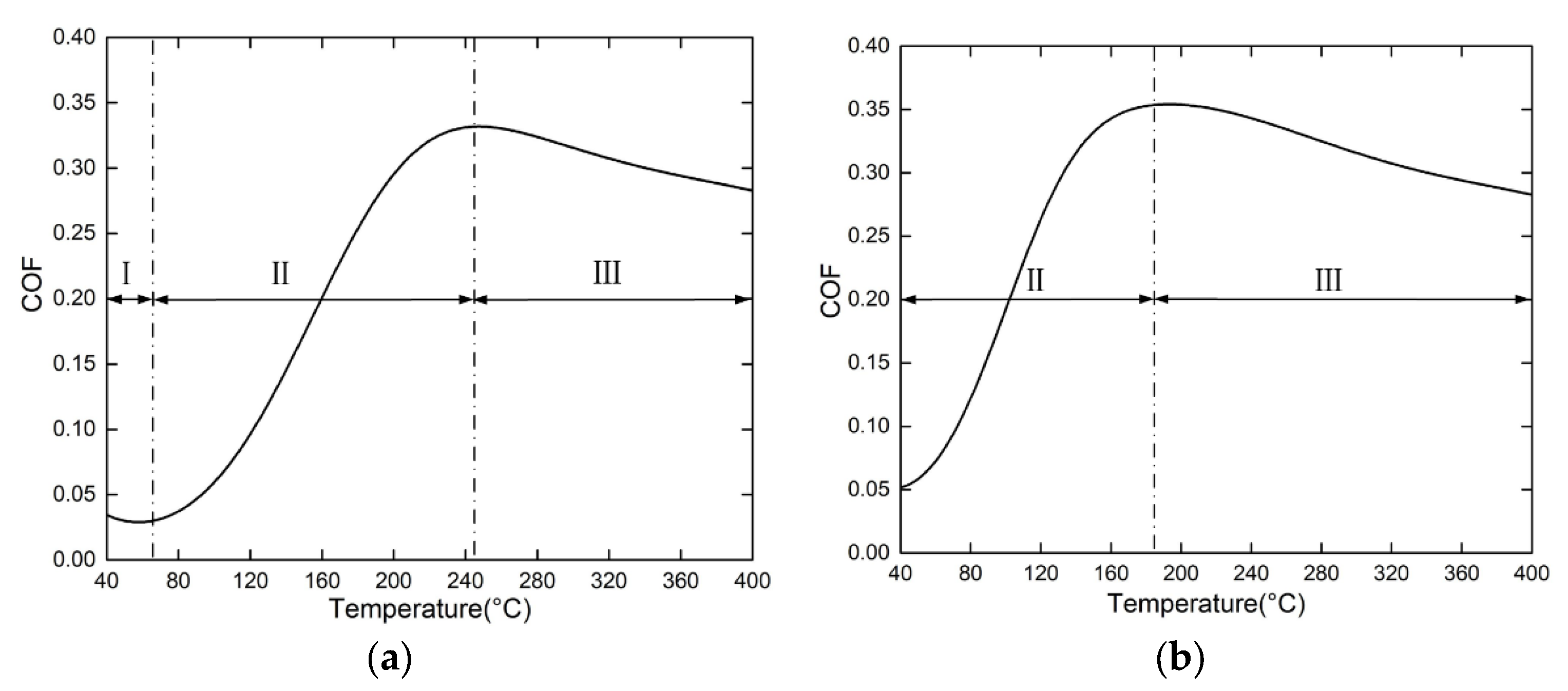
2.1. COF Model
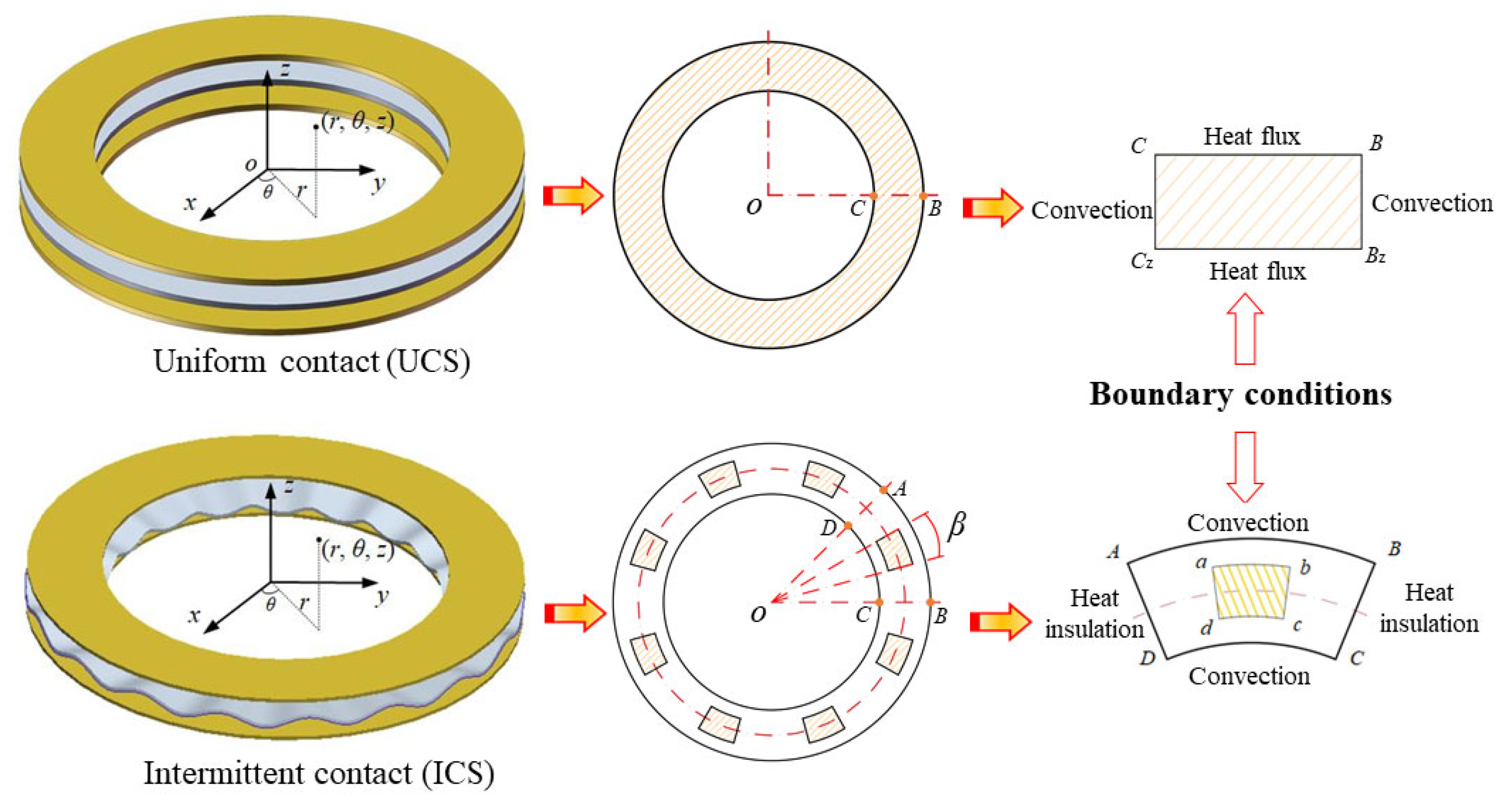
2.2. Thermodynamic Model
3. Experimental Method
4. Results and Discussion
4.1. Simulation Results
4.1.1. COF
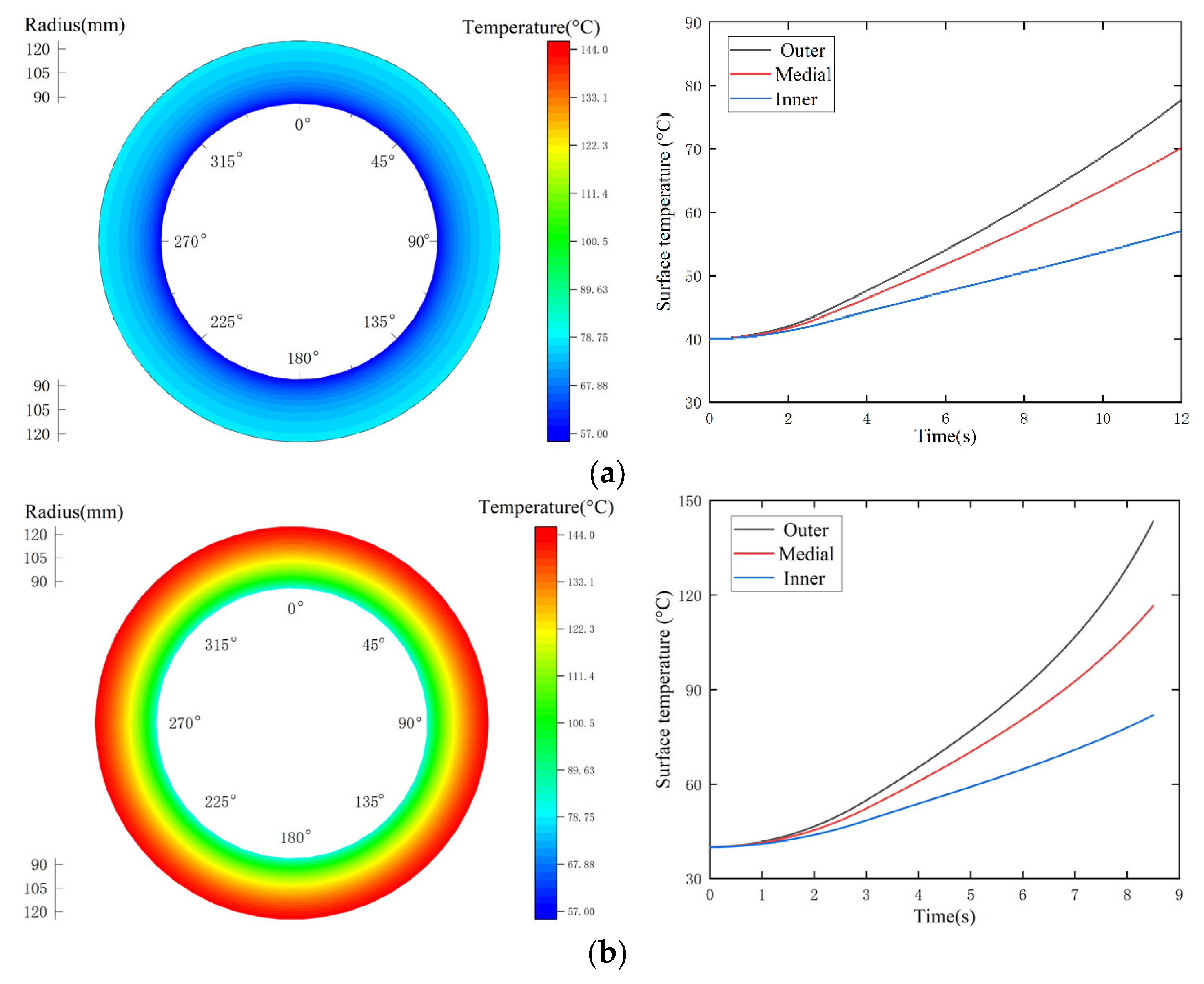
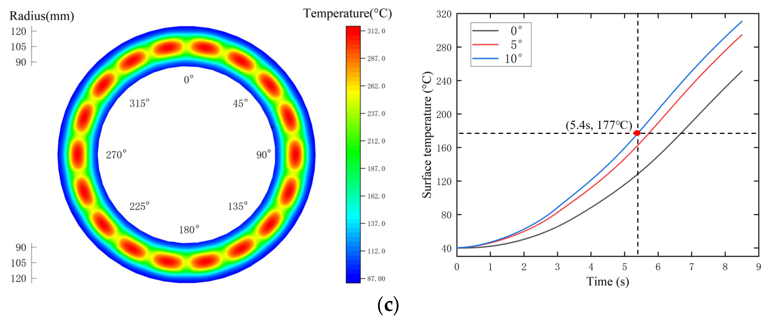
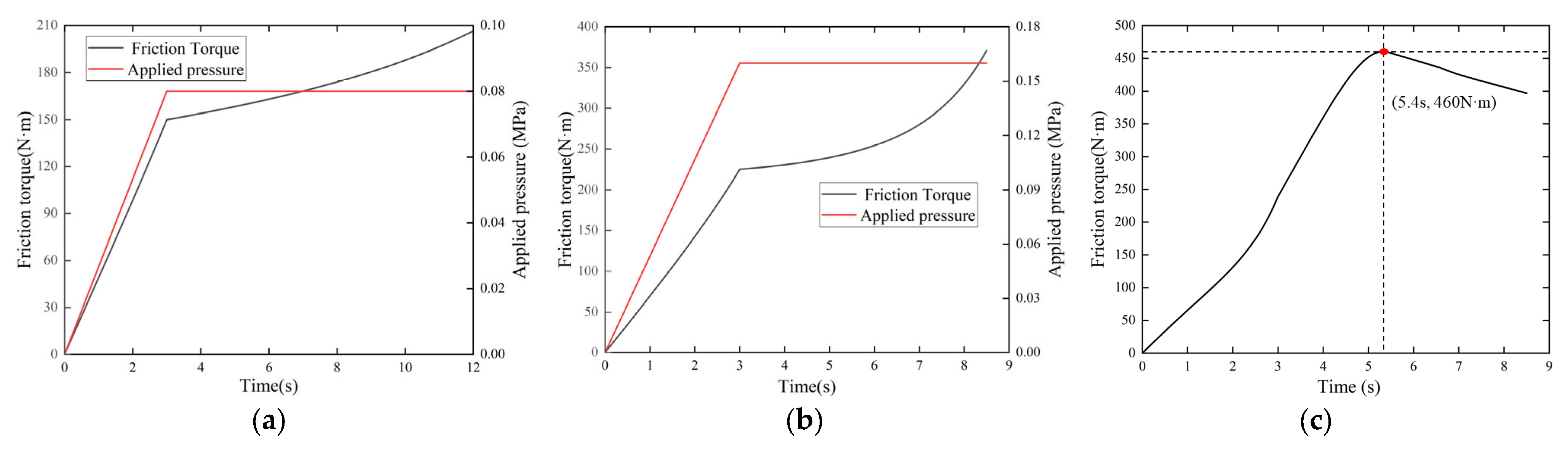
4.1.2. Thermodynamic Properties
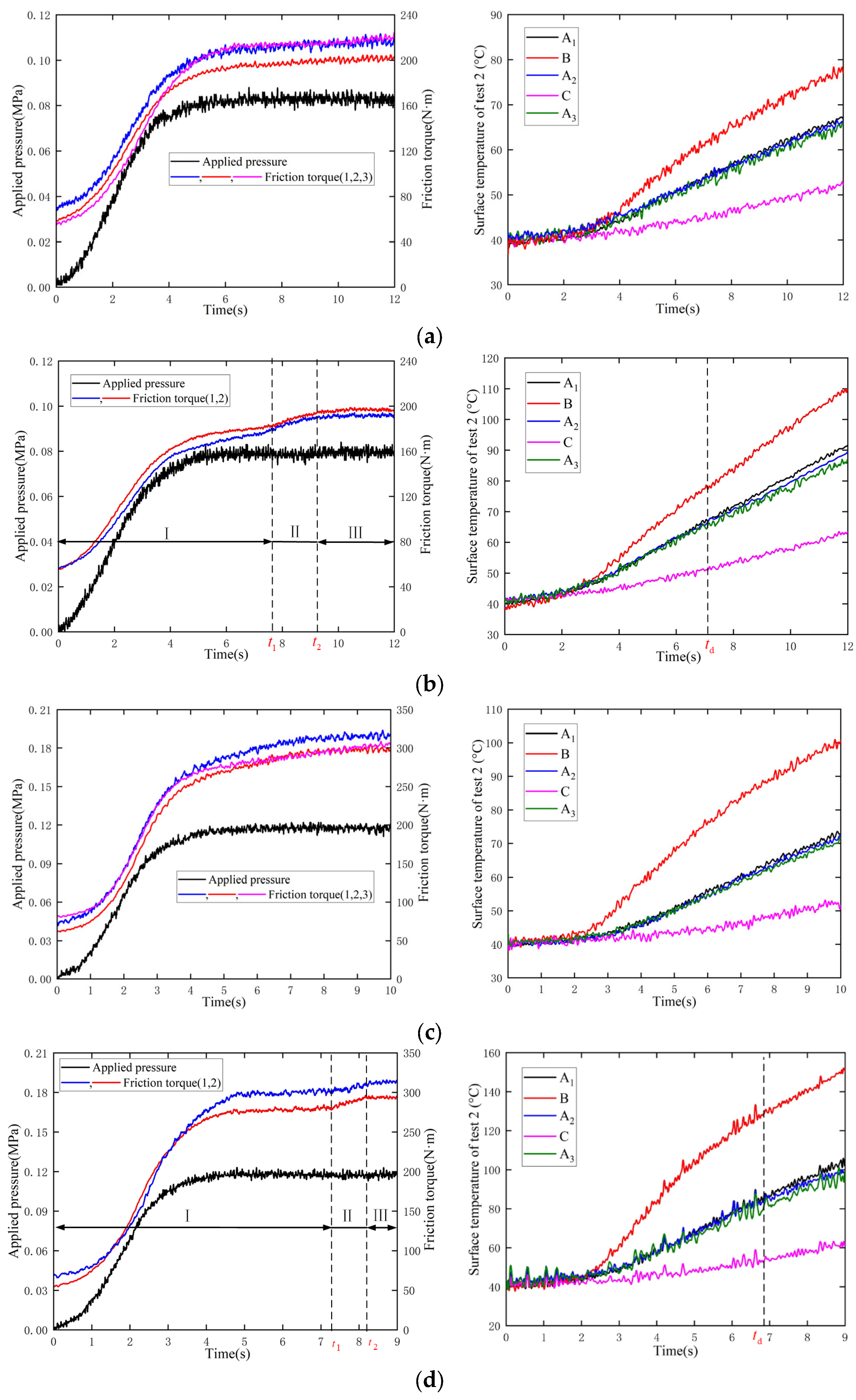
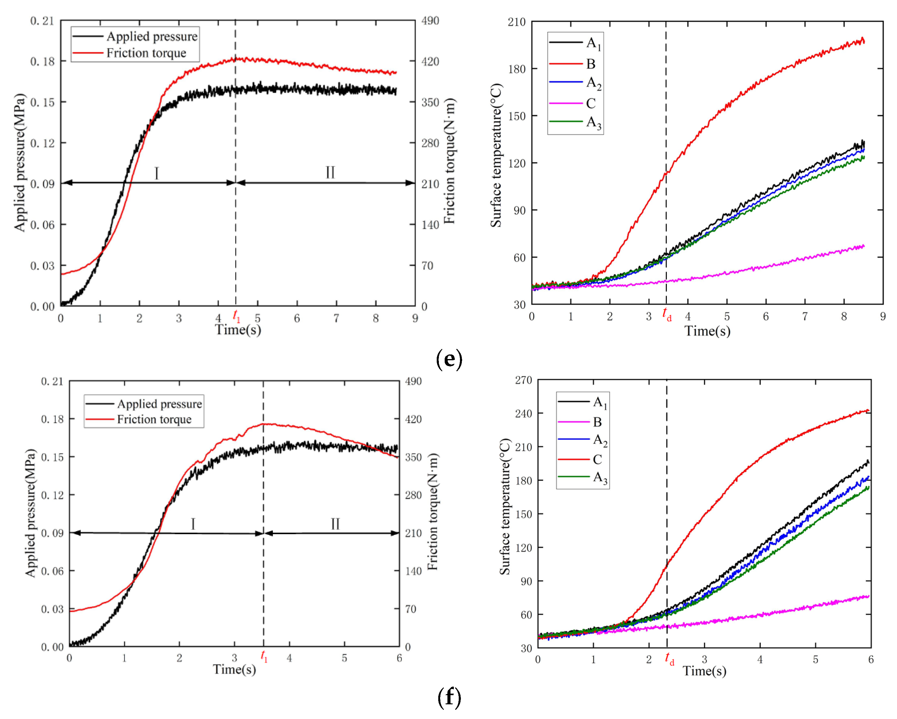
4.2. Experimental Results
5. Conclusions
- When the friction pairs are in the UCS, an increase in temperature causes the ATF film to gradually decrease, and thus friction torque shows a progressive increase trend;
- When the contact state changes from the UCS to the ICS, the local contact pressure and COF increase significantly, bringing about a step increase in friction torque. Subsequently, the circumferential and radial temperature differences of friction components expand dramatically;
- As the surface temperature increases in the ICS, the ATF film becomes difficult to form and gradually decreases, resulting in dry friction. Therefore, friction torque decays directly, and the surface temperature differences increase rapidly, leading to clutch failure.
Author Contributions
Funding
Institutional Review Board Statement
Informed Consent Statement
Data Availability Statement
Conflicts of Interest
Abbreviations
| Notation | Greek Symbols | ||
| c | specific heat (J/(kg·°C)) | α | relative oil film loss |
| h | thickness (mm) | β | central angle of contact zone (rad) |
| M | friction torque (N·m) | γ | heat partition factor |
| n | contact period | ε | adsorption heat |
| p | contact pressure (MPa) | θ | angular displacement (rad) |
| q | heat flux(J/(m2·s)) | κ | convection coefficient (W/(m2·°C)) |
| R | gas constant | λ | thermal conductivity (W/(m·°C)) |
| r | radius position (mm) | η | contact ratio |
| T | temperature (°C) | μ | coefficient of friction |
| t | time (s) | ρ | density (kg/m3) |
| z | axial position (mm) | ω | relative angular velocity (rad/s) |
| Subscript | |||
| f | friction disc | s | separate plate |
| i | inner radius | o | outer radius |
References
- Yevtushenko, A.; Grzes, P.; Ilyushenko, A.; Liashok, A. An Effect of a Carbon-Containing Additive in the structure of a friction material on temperature of the wet clutch disc. Materials 2022, 15, 464. [Google Scholar] [CrossRef] [PubMed]
- Schmiedt, M.; He, P.; Rinderknecht, S. Target state optimization: Drivability improvement for vehicles with dual clutch transmissions. Appl. Sci. 2022, 12, 10283. [Google Scholar] [CrossRef]
- Ganesh, K.C.; Dhanasekaran, K.; Saravanan, P.; Panda, R. Failure analysis of multi plate wet-clutch used in off-highway transmission. Eng. Fail. Anal. 2021, 127, 105534. [Google Scholar] [CrossRef]
- Sharifzadeh, M.; Pisaturo, M.; Senatore, A. Real-time identification of dry-clutch frictional torque in automated transmissions at launch condition. Proc. Inst. Mech. Eng. Part D J. Automob. Eng. 2020, 234, 586–598. [Google Scholar] [CrossRef]
- Šabík, V.; Futáš, P.; Pribulová, A. Failure analysis of a clutch wheel for wind turbines with the use of casting process simulation. Eng. Fail. Anal. 2022, 135, 106159. [Google Scholar] [CrossRef]
- Wu, Y.; Liu, Y.; Chen, H.; Chen, Y.; Xie, D. An investigation into the failure mechanism of severe abrasion of high-speed train brake discs on snowy days. Eng. Fail. Anal. 2019, 101, 121–134. [Google Scholar] [CrossRef]
- Audebert, N.; Barber, J.R.; Zagrodzki, P. Buckling of automatic transmission clutch plates due to thermoelastic/plastic residual stresses. J. Therm. Stresses 1998, 21, 309–326. [Google Scholar] [CrossRef]
- Xiong, C.; Ma, B.; Li, H.; Zhang, F.; Wu, D. Experimental study and thermal analysis on the buckling of friction components in multi-disc clutch. J. Therm. Stresses 2015, 38, 1323–1343. [Google Scholar]
- Li, M.; Ma, B.; Li, H.; Li, H.; Yu, L. Analysis of the thermal buckling of annular disks in clutches under the condition of radial temperature gradient. J. Therm. Stresses 2017, 40, 1275–1284. [Google Scholar] [CrossRef]
- Abdullah, O.I.; Akhtar, M.J.; Schlattmann, J. Investigation of thermo-elastic behavior of multidisk clutches. J. Tribol. 2015, 137, 011703. [Google Scholar] [CrossRef]
- Abdullah, O.I.; Schlattmann, J.; Senatore, A.; Sabri, L.A.; Al-Sahb, W.S.A. Effect of sliding speed on the thermal stresses of single-disk friction clutches. J. Fail. Anal. Prev. 2020, 20, 1534–1540. [Google Scholar] [CrossRef]
- Zhao, E.; Ma, B.; Li, H. The tribological characteristics of Cu-based friction pairs in a wet multidisk clutch under nonuniform contact. J. Tribol. 2018, 140, 11401. [Google Scholar] [CrossRef]
- Yu, L.; Ma, B.; Chen, M.; Li, H.; Liu, J.; Li, M. Investigation on the failure mechanism and safety mechanical-thermal boundary of a multi-disc clutch. Eng. Fail. Anal. 2019, 103, 319–334. [Google Scholar] [CrossRef]
- Thakur, M.K.; Sarkar, C. Lubrication performance of magnetorheological fluid in shear mode magnetorheological clutch with and without groove. Proc. Inst. Mech. Eng. Part J J. Eng. Tribol. 2022, 236, 338–355. [Google Scholar] [CrossRef]
- Yang, L.; Ma, B.; Ahmadian, M.; Li, H.; Vick, B. Pressure distribution of a multidisc clutch suffering frictionally induced thermal load. Tribol. T. 2016, 59, 983–992. [Google Scholar] [CrossRef]
- Gong, Y.; Wang, P.; Ge, W.; Yi, Y.B. Numerical simulation and mechanism analysis on the concave deformation of automotive dry clutch pressure plate. Appl. Sci. 2019, 9, 5017. [Google Scholar] [CrossRef] [Green Version]
- Farfan-Cabrera, L.I.; Gallardo-Hernández, E.A.; Pérez-González, J.; Marín-Santibáñez, B.M.; Lewis, R.; González-Lamas, A.K. Evaluation of thermo-oxidized Jatropha bio-oil in lubrication of actual wet clutch materials. Proc. Inst. Mech. Eng. Part J J. Eng. Tribol. 2021, 235, 2021–2033. [Google Scholar] [CrossRef]
- Hansen, E.; Frohnapfel, B.; Codrignani, A. Sensitivity of the Stribeck curve to the pin geometry of a pin-on-disc tribometer. Tribol. Int. 2020, 151, 106488. [Google Scholar] [CrossRef]
- Neupert, T.; Bartel, D. High-resolution 3D CFD multiphase simulation of the flow and the drag torque of wet clutch discs considering free surfaces. Tribol. Int. 2019, 129, 283–296. [Google Scholar] [CrossRef]
- Yao, S.; Liu, Q.; Cui, H.; Feng, S. An improved method for evaluating the rotational speed stability of a hydro-viscous clutch in mixed lubrication. Friction 2015, 3, 47–55. [Google Scholar] [CrossRef] [Green Version]
- Pisaturo, M.; Senatore, A. Simulation of engagement control in automotive dry-clutch and temperature field analysis through finite element model. Appl. Therm. Eng. 2016, 93, 958–966. [Google Scholar] [CrossRef]
- Thakur, M.K.; Sarkar, C. Investigation of different groove profile effects on torque transmission in shear mode magnetorheological clutch: Numerical simulation and experimental study. J. Tribol. 2021, 143, 091801. [Google Scholar] [CrossRef]
- Kong, J.; Jang, S. Temperature analysis of wet clutch surfaces during clutch engagement processes based on friction pad patterns. Int. J. Automot. Technol. 2020, 21, 813–822. [Google Scholar] [CrossRef]
- Bao, H.; Huang, W.; Lu, F. Investigation of engagement characteristics of a multi-disc wet friction clutch. Tribol. Int. 2021, 159, 106940. [Google Scholar]
- Cui, J.; Hou, P.; Zhang, B.; Zhao, X. Investigation of flow between deformed disks in hydro-viscous drive. Tribol. Int. 2018, 121, 287–301. [Google Scholar] [CrossRef]
- Martin, J.M.; Ohmae, N. Principles and Applications of Tribology, 2nd ed.; Elsevier: Amsterdam, The Netherlands, 2008. [Google Scholar]
- Li, M.; Ma, B.; Li, H.; Zhao, E.H.; Du, Q.; Li, H. The influence of local contact of Cu-based friction pairs on friction coefficient. Trans. Beijing Inst. Technol. 2019, 39, 53–57. [Google Scholar]
- Zhao, E.; Ma, B.; Li, H. Wear and lubrication behaviors of Cu-based friction pairs with asperity contacts: Numerical and experimental studies. Tribol. Lett. 2017, 65, 69. [Google Scholar] [CrossRef]
- Yu, L.; Ma, B.; Chen, M.; Li, H.; Liu, J. Investigation on the thermodynamic characteristics of the deformed separate plate in a multi-disc clutch. Eng. Fail. Anal. 2020, 110, 104385. [Google Scholar] [CrossRef]
- Bao, H.; Kong, W.; Hou, X.; Zhu, R. Analysis on temperature field of friction pair of aviation friction clutch based on different groove shapes of friction disk. J. Mech. Sci. Technol. 2021, 35, 3735–3742. [Google Scholar] [CrossRef]
- Xiao, J.K.; Xiao, S.X.; Chen, J.; Zhang, C. Wear mechanism of Cu-based brake pad for high-speed train braking at speed of 380 km/h. Tribol. Int. 2020, 150, 106357. [Google Scholar] [CrossRef]


| Parameters | Value |
|---|---|
| Viscosity grade | SAE 15 W–40 |
| Flash point | 255 °C |
| Molar mass (Mmol) | 310 g/mol |
| Gas constant (R) | 8.3 |
| Critical temperature (Tcr) | 353.15 K |
| Adsorption heat (ε) | 31,425 J/mol |
| Variable | Friction Core | Friction Lining | Separate Plate |
|---|---|---|---|
| Density, kg/m3 | 7800 | 5500 | 7800 |
| Specific heat, J/(kg·°C) | 487 | 460 | 487 |
| Thermal conductivity, W/(m·°C) | 45.9 | 9.3 | 45.9 |
| Radius, mm | 86/125 | 86/125 | 86/125 |
| Test | 1 | 2 | 3 | 4 | 5 | 6 |
|---|---|---|---|---|---|---|
| Applied pressure (MPa) | 0.08 | 0.08 | 0.12 | 0.12 | 0.16 | 0.16 |
| Rotating speed (rpm) | 150 | 300 | 150 | 300 | 300 | 600 |
| Sliding time (s) | 12 | 12 | 10 | 9 | 8.5 | 5.96 |
| Repeated times | 3 | 2 | 3 | 2 | 1 | 1 |
Publisher’s Note: MDPI stays neutral with regard to jurisdictional claims in published maps and institutional affiliations. |
© 2022 by the authors. Licensee MDPI, Basel, Switzerland. This article is an open access article distributed under the terms and conditions of the Creative Commons Attribution (CC BY) license (https://creativecommons.org/licenses/by/4.0/).
Share and Cite
Yu, L.; Zheng, C.; Wang, L.; Wu, J.; Jia, R. Influences of the Contact State between Friction Pairs on the Thermodynamic Characteristics of a Multi-Disc Clutch. Materials 2022, 15, 7758. https://doi.org/10.3390/ma15217758
Yu L, Zheng C, Wang L, Wu J, Jia R. Influences of the Contact State between Friction Pairs on the Thermodynamic Characteristics of a Multi-Disc Clutch. Materials. 2022; 15(21):7758. https://doi.org/10.3390/ma15217758
Chicago/Turabian StyleYu, Liang, Changsong Zheng, Liyong Wang, Jianpeng Wu, and Ran Jia. 2022. "Influences of the Contact State between Friction Pairs on the Thermodynamic Characteristics of a Multi-Disc Clutch" Materials 15, no. 21: 7758. https://doi.org/10.3390/ma15217758