
Topology Optimization for Hybrid Lattice Compliant Mechanisms with Multiple Microstructures


Abstract
:1. Introduction
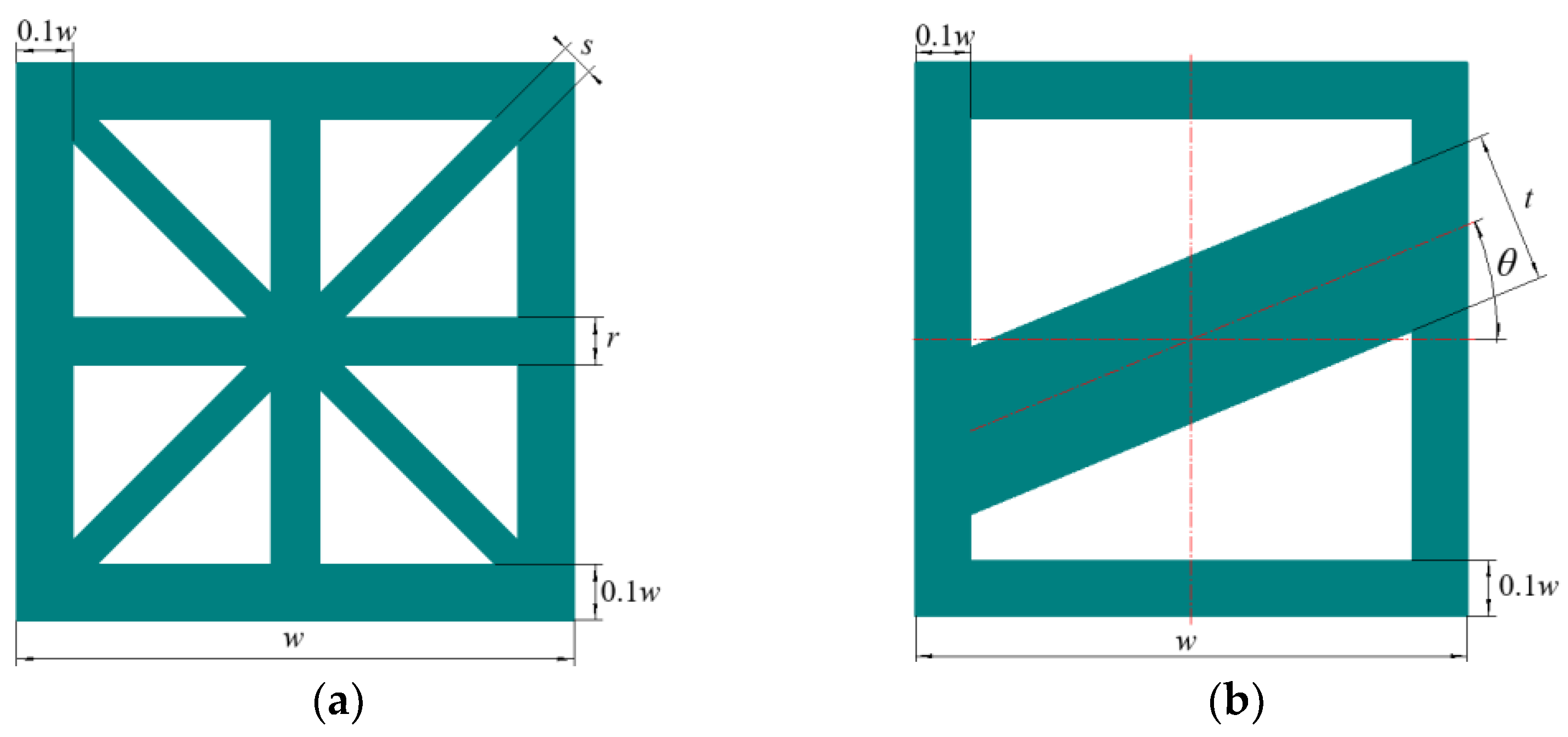
2. Effective Elastic Properties of Multiple Lattice Microstructures
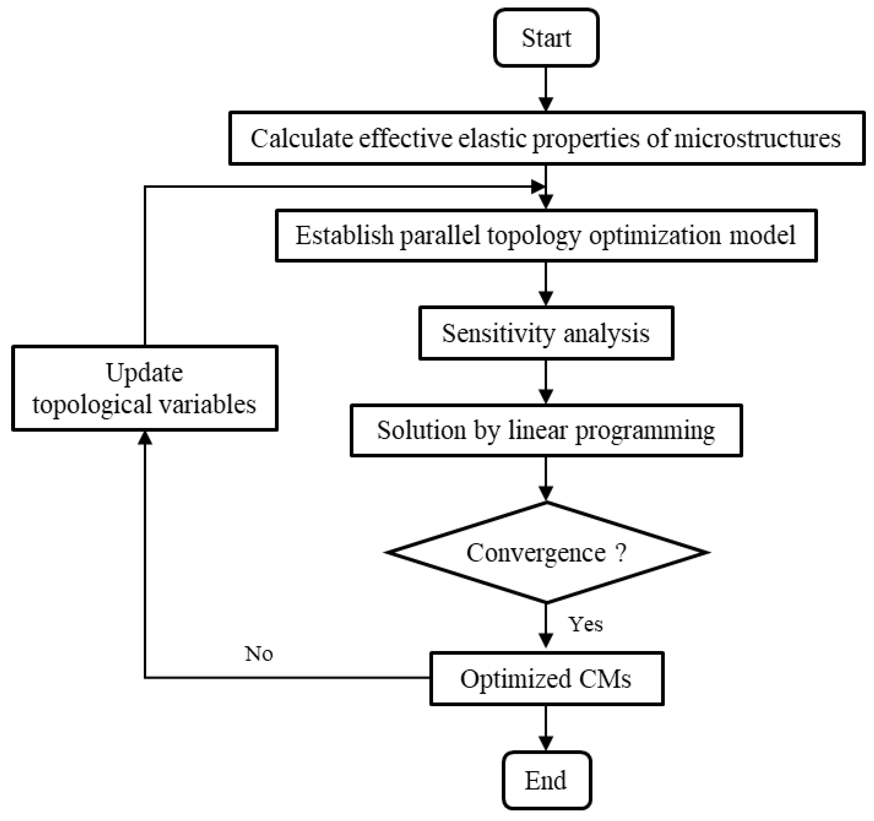
3. Parallel Topology Optimization Formulations for HLCMs
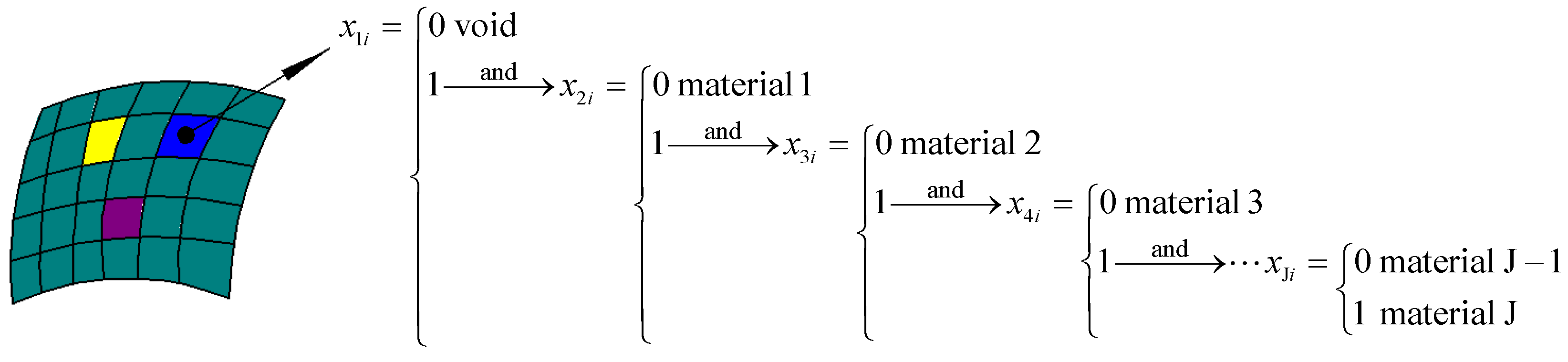
3.1. Parallel Topology Optimization Model
3.2. Sensitivity Analysis and Solution
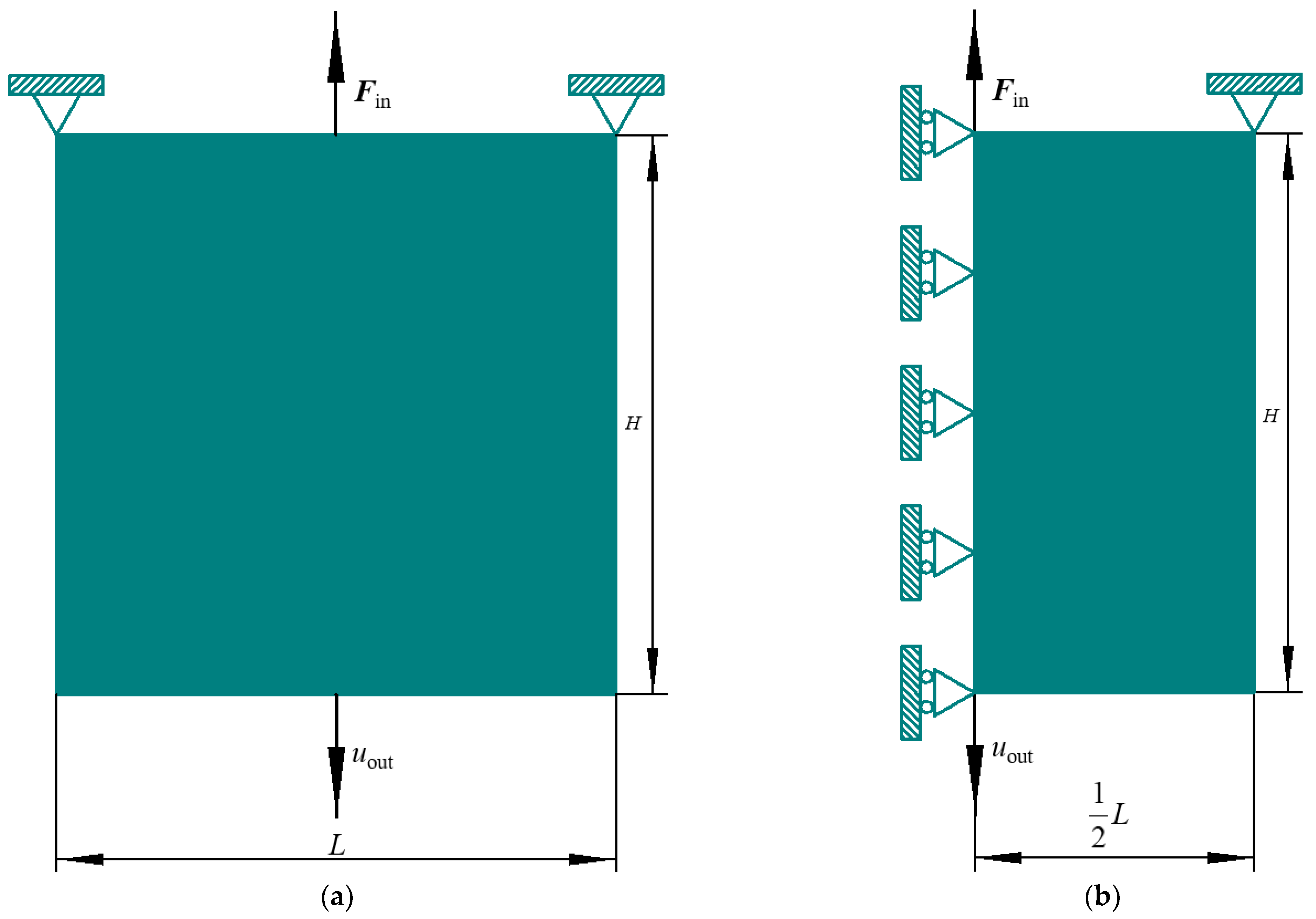
4. Numerical Examples
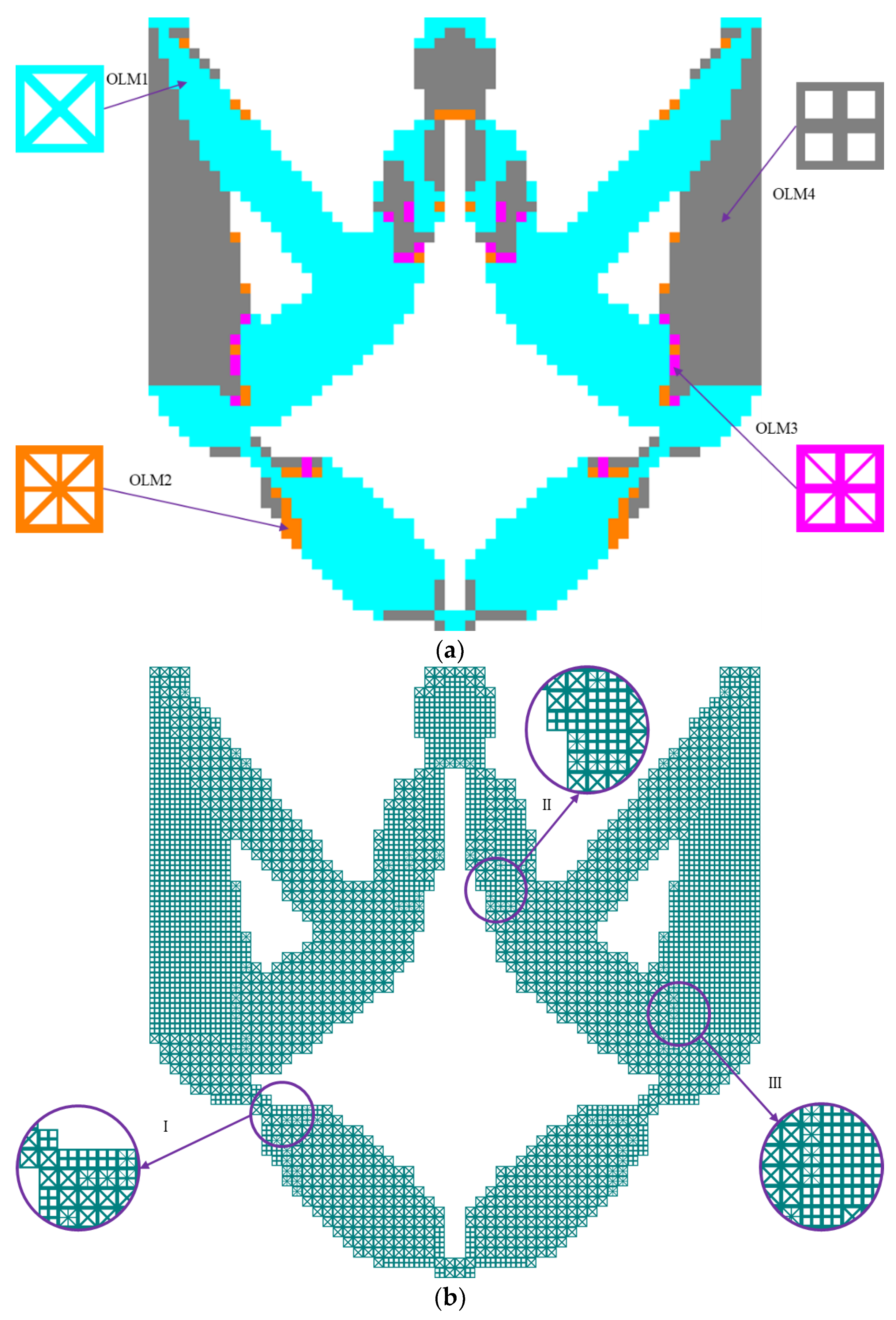
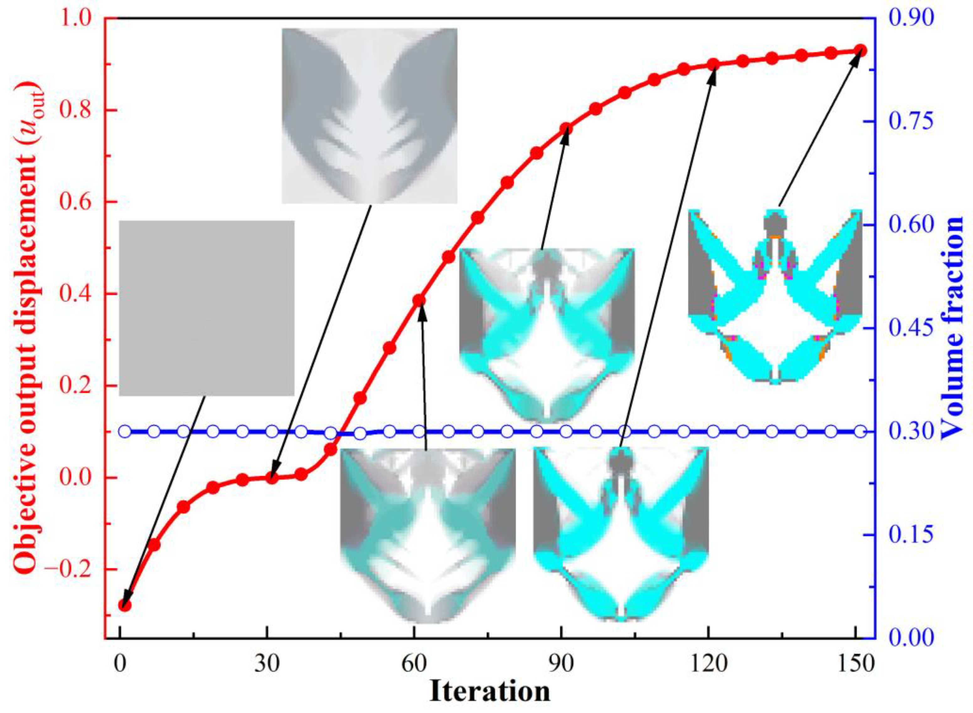
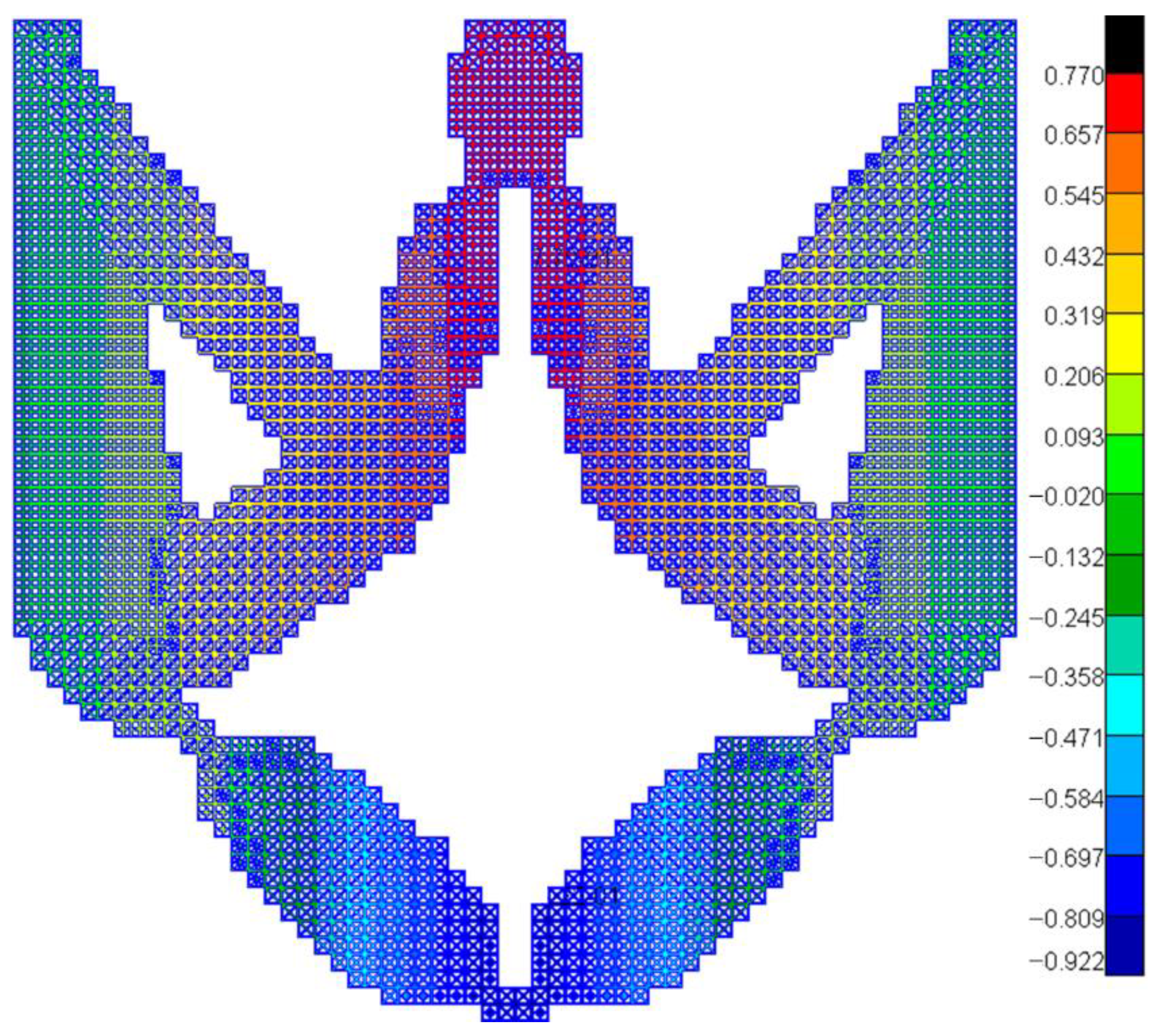
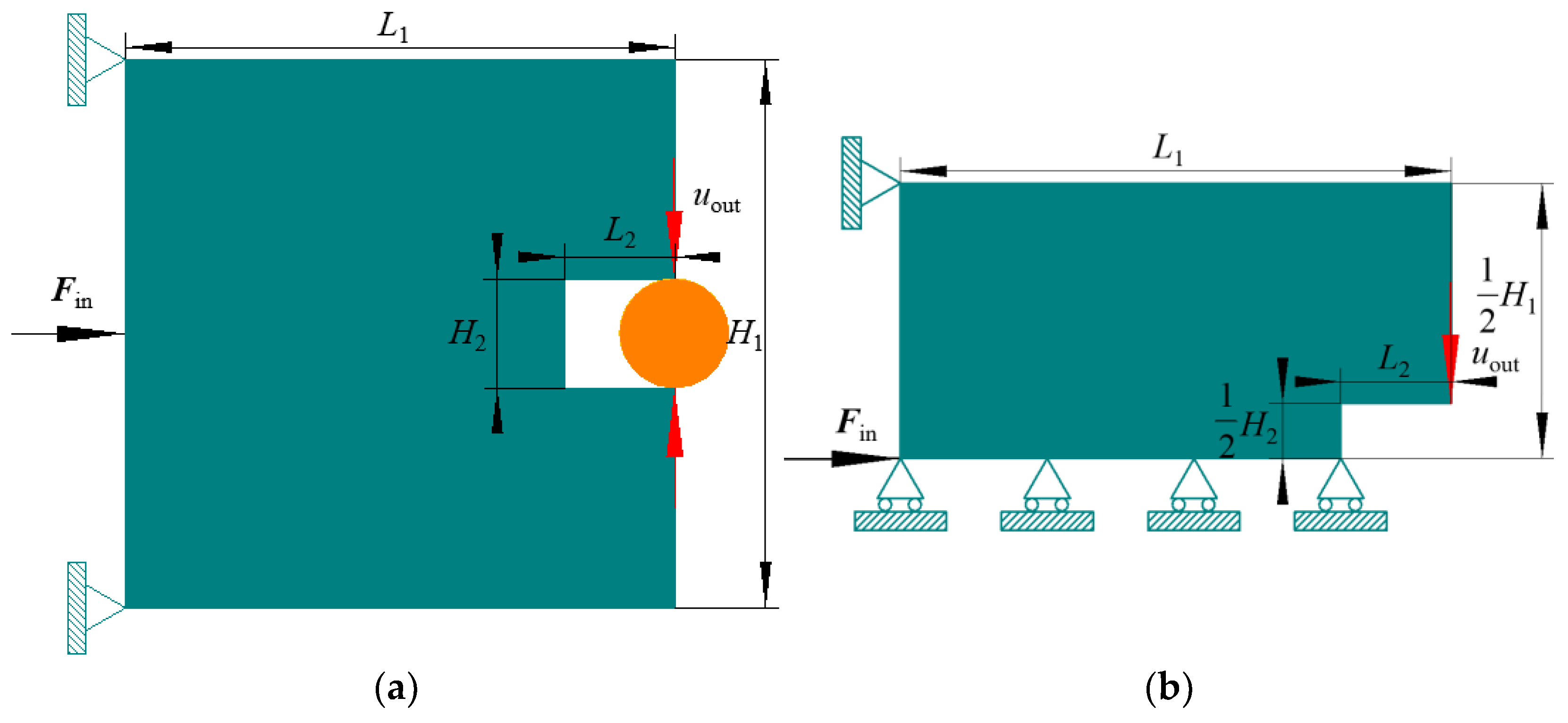
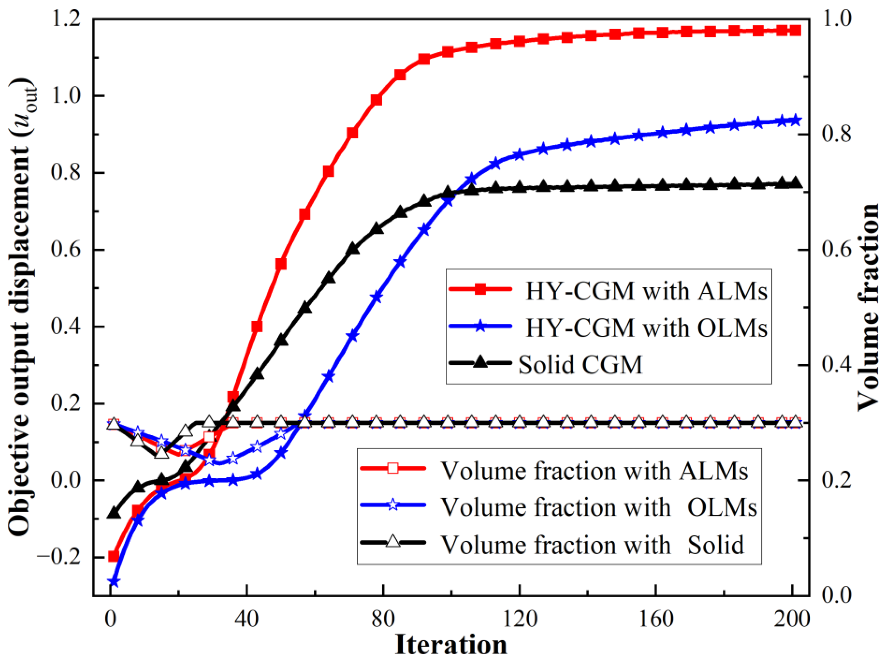
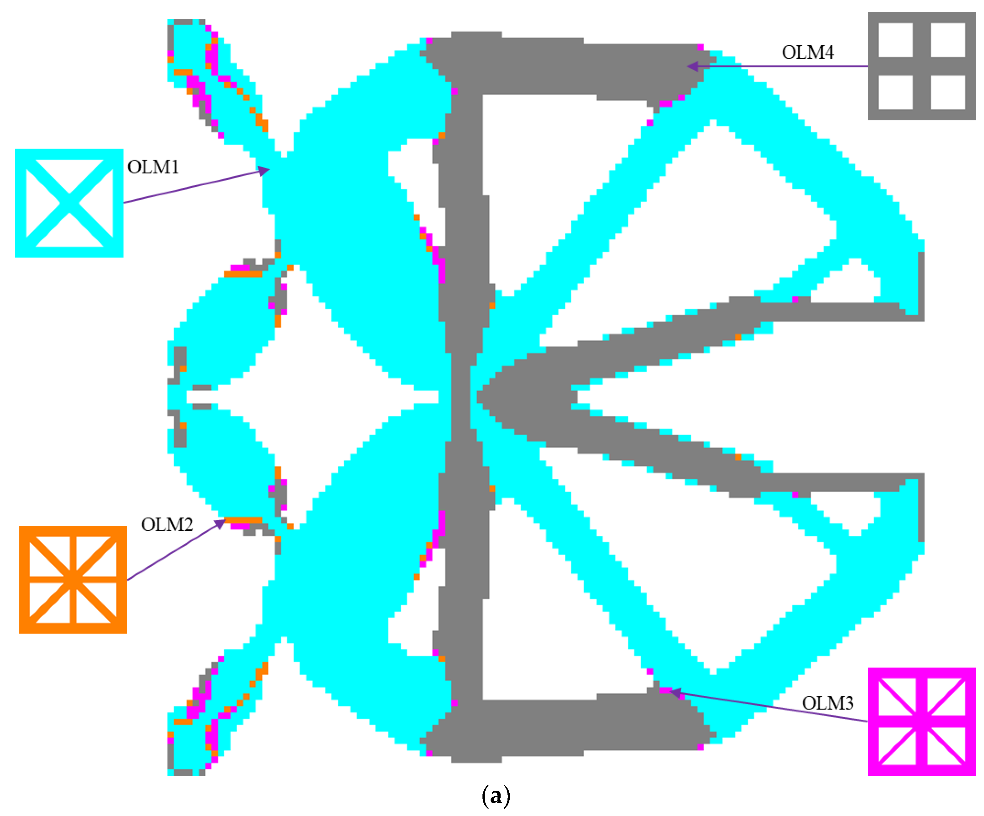
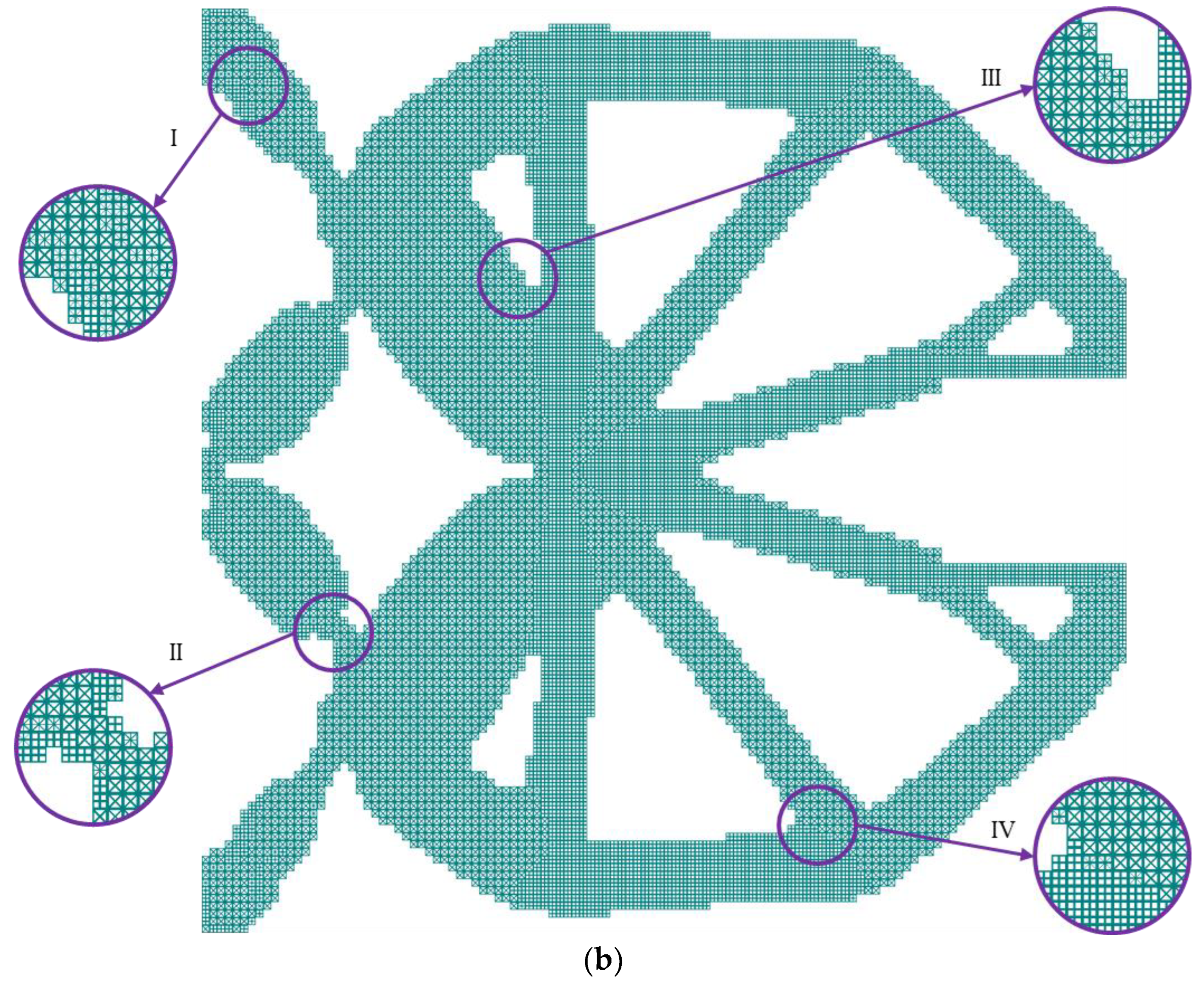
4.1. Displacement Inverter Mechanism
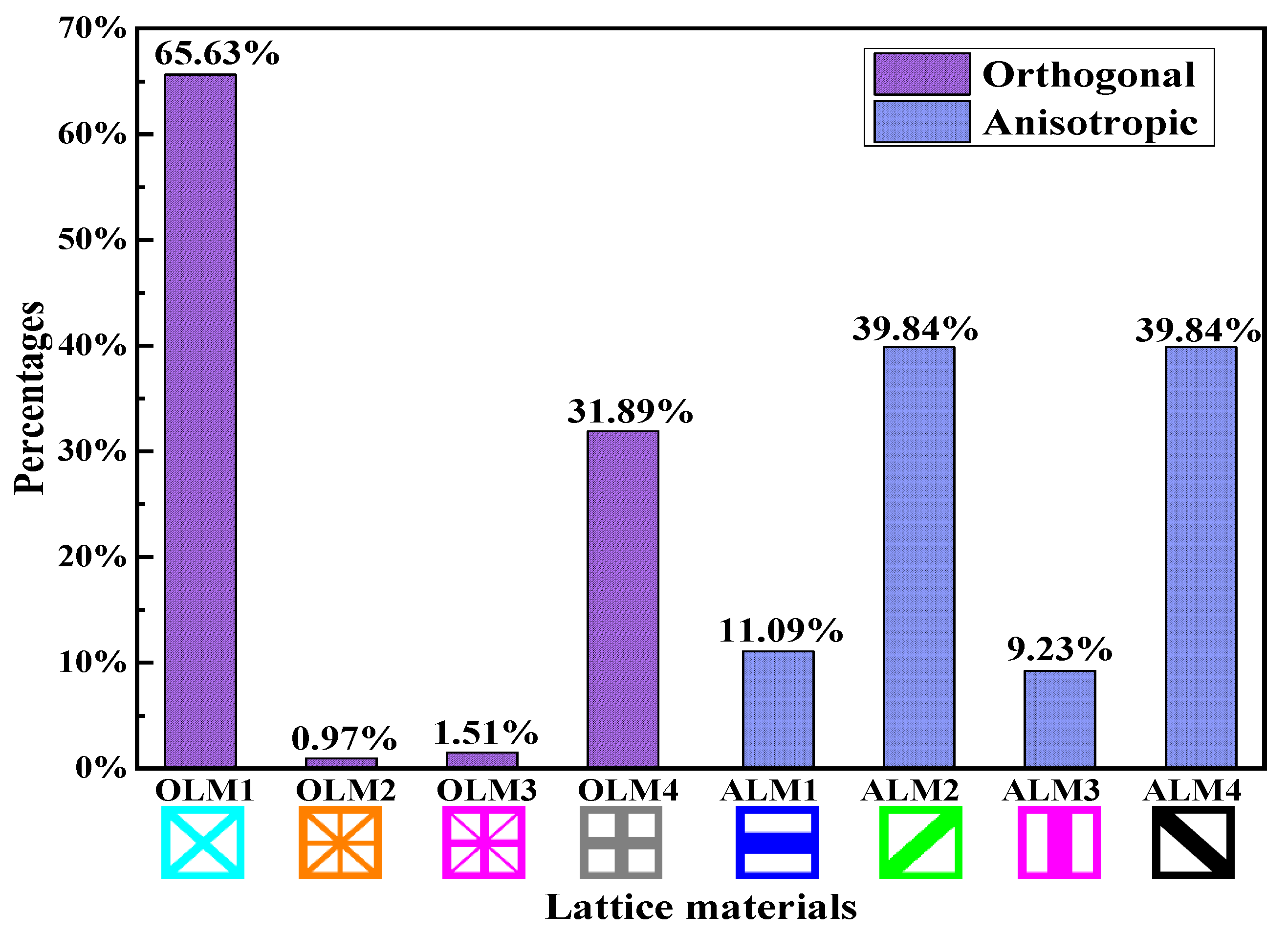
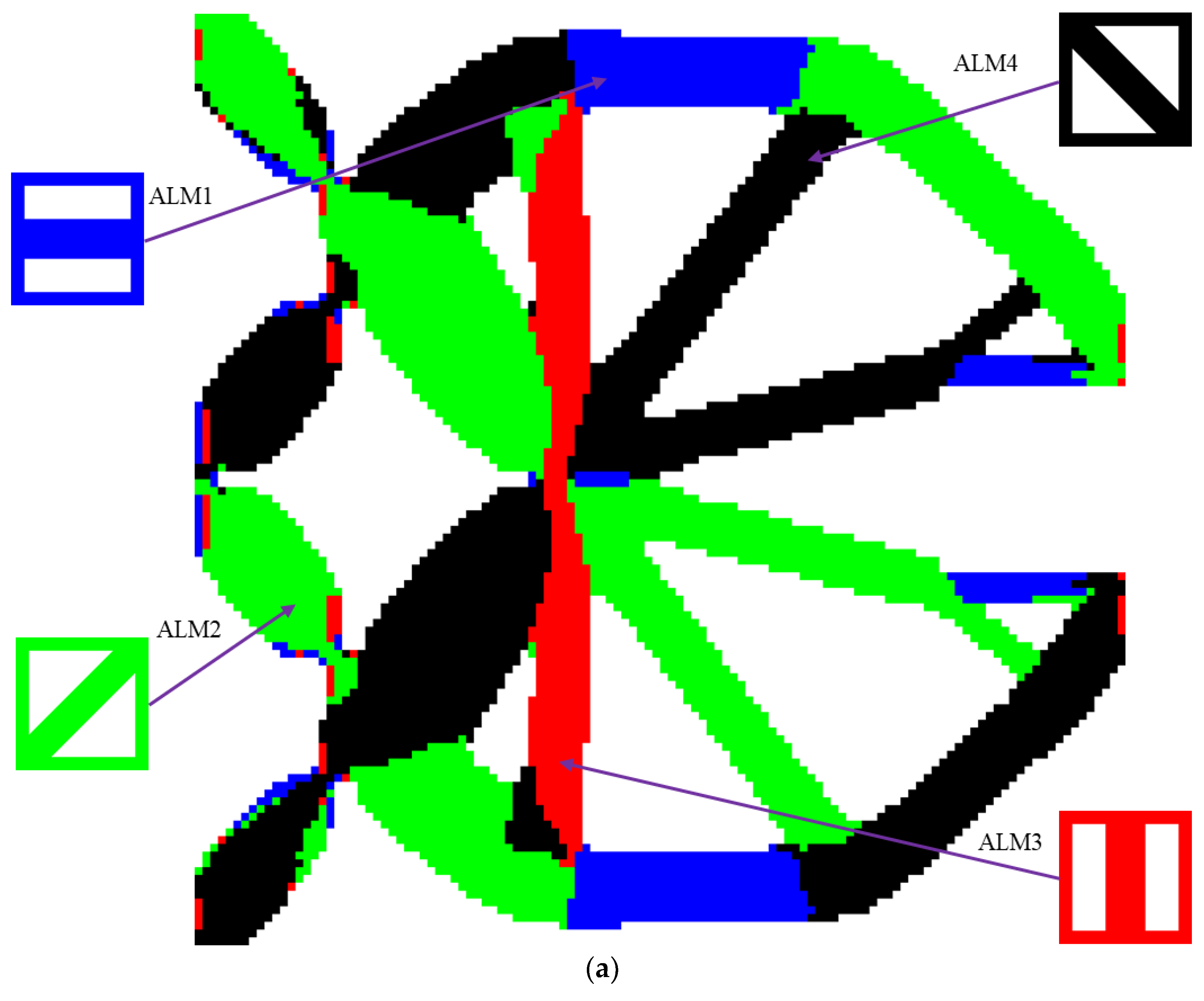
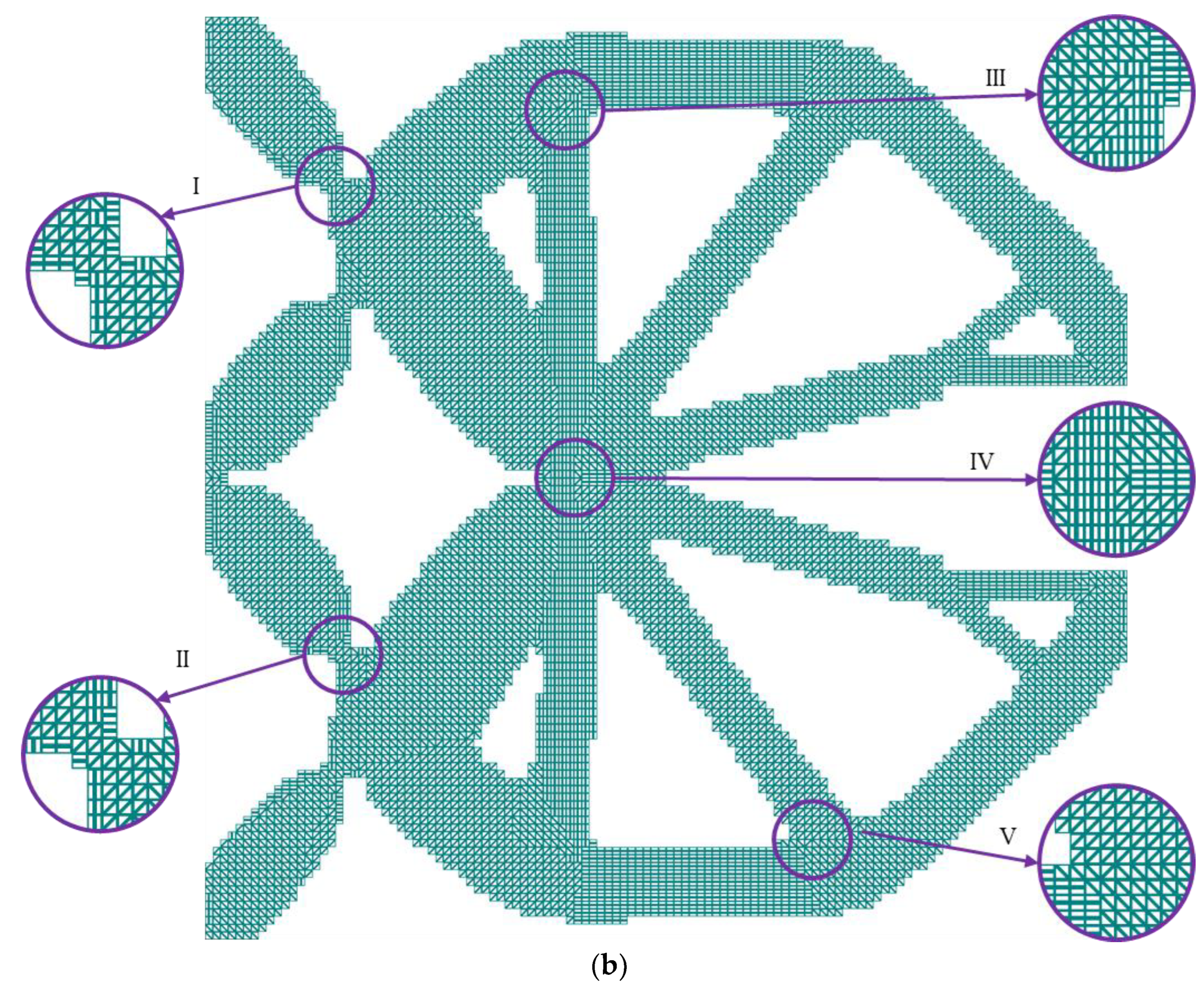
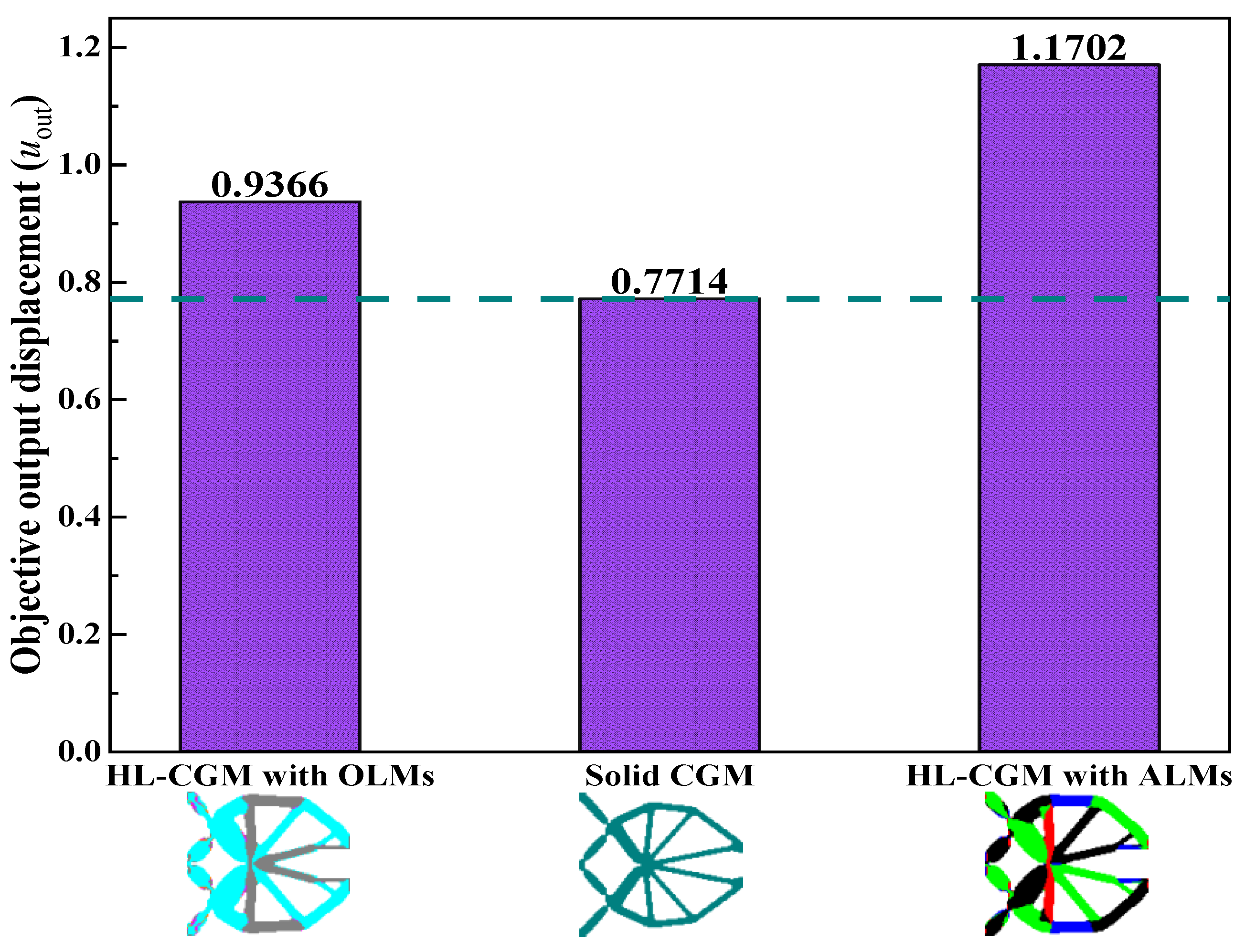
4.2. Compliant Gripper Mechanism
5. Conclusions
Author Contributions
Funding
Institutional Review Board Statement
Informed Consent Statement
Data Availability Statement
Conflicts of Interest
References
- Zhu, B.; Zhang, X.; Zhang, H.; Liang, J.; Zang, H.; Li, H.; Wang, R. Design of Compliant Mechanisms Using Continuum Topology Optimization: A Review. Mech. Mach. Theory 2020, 143, 103622. [Google Scholar] [CrossRef]
- Verotti, M.; Berselli, G.; Bruzzone, L.; Baggetta, M.; Fanghella, P. Design, Simulation and Testing of an Isotropic Compliant Mechanism. Precis. Eng. 2021, 72, 730–737. [Google Scholar] [CrossRef]
- Liu, Y.; Zhang, Y.; Xu, Q. Design and Control of a Novel Compliant Constant-Force Gripper Based on Buckled Fixed-Guided Beams. IEEE/ASME Trans. Mechatron. 2017, 22, 476–486. [Google Scholar] [CrossRef]
- Tian, Y.; Zhang, D.; Shirinzadeh, B. Dynamic Modelling of a Flexure-Based Mechanism for Ultra-Precision Grinding Operation. Precis. Eng. 2011, 35, 554–565. [Google Scholar] [CrossRef]
- Ando, B.; Baglio, S.; L’Episcopo, G.; Trigona, C. Investigation on Mechanically Bistable Mems Devices for Energy Harvesting From Vibrations. J. Microelectromech. Syst. 2012, 21, 779–790. [Google Scholar] [CrossRef]
- Cirelli, M.; Cera, M.; Pennestrì, E.; Valentini, P.P. Nonlinear Design Analysis of Centrifugal Pendulum Vibration Absorbers: An Intrinsic Geometry-Based Framework. Nonlinear Dyn. 2020, 102, 1297–1318. [Google Scholar] [CrossRef]
- Zhao, H.; Zhao, C.; Ren, S.; Bi, S. Analysis and Evaluation of a Near-Zero Stiffness Rotational Flexural Pivot. Mech. Mach. Theory 2019, 135, 115–129. [Google Scholar] [CrossRef]
- Dearden, J.; Grames, C.; Orr, J.; Jensen, B.D.; Magleby, S.P.; Howell, L.L. Cylindrical Cross-Axis Flexural Pivots. Precis. Eng. 2018, 51, 604–613. [Google Scholar] [CrossRef]
- Krishnan, G.; Kim, C.; Kota, S. An Intrinsic Geometric Framework for the Building Block Synthesis of Single Point Compliant Mechanisms. J. Mech. Robot. 2011, 3, 011001. [Google Scholar] [CrossRef]
- Kim, C.J.; Moon, Y.; Kota, S. A Building Block Approach to the Conceptual Synthesis of Compliant Mechanisms Utilizing Compliance and Stiffness Ellipsoids. J. Mech. Des. 2008, 130, 022308. [Google Scholar] [CrossRef]
- Sigmund, O. On the Design of Compliant Mechanisms Using Topology Optimization. Mech. Struct. Mach. Int. J. 1997, 25, 493–524. [Google Scholar] [CrossRef]
- Tran, A.V.; Zhang, X.; Zhu, B. The Development of a New Piezoresistive Pressure Sensor for Low Pressures. IEEE Trans. Ind. Electron. 2018, 65, 6487–6496. [Google Scholar] [CrossRef]
- Cao, L.; Dolovich, A.T.; Chen, A.; Zhang, W.C. Topology Optimization of Efficient and Strong Hybrid Compliant Mechanisms Using a Mixed Mesh of Beams and Flexure Hinges with Strength Control. Mech. Mach. Theory 2018, 121, 213–227. [Google Scholar] [CrossRef]
- Wu, J.; Sigmund, O.; Groen, J.P. Topology Optimization of Multi-Scale Structures: A Review. Struct. Multidiscip. Optim. 2021, 63, 1455–1480. [Google Scholar] [CrossRef]
- Bendsøe, M.P. Optimal Shape Design as a Material Distribution Problem. Struct. Optim. 1989, 1, 193–202. [Google Scholar] [CrossRef]
- Groen, J.P.; Langelaar, M.; Sigmund, O.; Ruess, M. Higher-Order Multi-Resolution Topology Optimization Using the Finite Cell Method. Int. J. Numer. Meth. Eng. 2017, 110, 903–920. [Google Scholar] [CrossRef] [Green Version]
- Bendsøe, M.P.; Kikuchi, N. Generating Optimal Topologies in Structural Design Using a Homogenization Method. Comput. Method. Appl. M. 1988, 2, 197–224. [Google Scholar] [CrossRef]
- Ye, M.; Gao, L.; Wang, F.; Li, H. A Novel Design Method for Energy Absorption Property of Chiral Mechanical Metamaterials. Materials 2021, 14, 5386. [Google Scholar] [CrossRef]
- Zheng, J.; Luo, Z.; Jiang, C.; Gao, J. Robust Topology Optimization for Concurrent Design of Dynamic Structures Under Hybrid Uncertainties. Mech. Syst. Signal Process. 2019, 120, 540–559. [Google Scholar] [CrossRef]
- Wang, M.Y.; Wang, X.; Guo, D. A Level Set Method for Structural Topology Optimization. Comput. Methods Appl. Mech. Eng. 2003, 192, 227–246. [Google Scholar] [CrossRef]
- Sun, Z.; Song, Z.; Song, J.; Li, H.; Guo, X. Structural Optimization of Fiber-Reinforced Material Based On Moving Morphable Components (Mmcs). Acta Mech. Solida Sin. 2022, 35, 632–646. [Google Scholar] [CrossRef]
- Guo, X.; Zhang, W.; Zhong, W. Doing Topology Optimization Explicitly and Geometrically—A New Moving Morphable Components Based Framework. J. Appl. Mech. 2014, 81, 081009. [Google Scholar] [CrossRef]
- Xie, Y.M.; Steven, G.P. A Simple Evolutionary Procedure for Structural Optimization. Comput. Struct. 1993, 49, 885–896. [Google Scholar] [CrossRef]
- Xue, L.; Wen, G.; Wang, H.; Liu, J. Eigenvectors-Guided Topology Optimization to Control the Mode Shape and Suppress the Vibration of the Multi-Material Plate. Comput. Method Appl. Mech. Eng. 2022, 391, 114560. [Google Scholar] [CrossRef]
- Carraturo, M.; Rocca, E.; Bonetti, E.; Hömberg, D.; Reali, A.; Auricchio, F. Graded-Material Design Based On Phase-Field and Topology Optimization. Comput. Mech. 2019, 64, 1589–1600. [Google Scholar] [CrossRef] [Green Version]
- Takezawa, A.; Nishiwaki, S.; Kitamura, M. Shape and Topology Optimization Based On the Phase Field Method and Sensitivity Analysis. J. Comput. Phys. 2010, 229, 2697–2718. [Google Scholar] [CrossRef] [Green Version]
- Zhang, X.; Ye, H.; Wei, N.; Tao, R.; Luo, Z. Design Optimization of Multifunctional Metamaterials with Tunable Thermal Expansion and Phononic Bandgap. Mater. Des. 2021, 209, 109990. [Google Scholar] [CrossRef]
- Wei, N.; Ye, H.; Zhang, X.; Wang, W.; Sui, Y. Lightweight Topology Optimization of Graded Lattice Structures with Displacement Constraints Based On an Independent Continuous Mapping Method. Acta Mech. Sin. 2022, 38, 421352. [Google Scholar] [CrossRef]
- Nishiwaki, S.; Frecker, M.I.; Min, S.; Kikuchi, N. Topology Optimization of Compliant Mechanisms Using the Homogenization Method. Int. J. Numer. Meth. Eng. 1998, 42, 535–559. [Google Scholar] [CrossRef]
- Larsen, U.D.; Sigmund, O.; Bouwstra, S. Design and Fabrication of Compliant Micromechanisms and Structures with Negative Poisson’s Ratio. J. Microelectromech. Syst. 1997, 6, 99–106. [Google Scholar] [CrossRef]
- Sigmund, O. Design of Multiphysics Actuators Using Topology Optimization—Part II: Two-Material Structures. Comput. Methods Appl. Mech. Eng. 2001, 190, 6605–6627. [Google Scholar] [CrossRef]
- Wang, N.F.; Hu, K.; Zhang, X.M. Hierarchical Optimization for Topology Design of Multi-Material Compliant Mechanisms. Eng. Optimiz. 2017, 49, 2013–2035. [Google Scholar] [CrossRef]
- Gaynor, G.T.; Meisel, N.A.; Williams, C.B.; Guest, J.K. Multiple-Material Topology Optimization of Compliant Mechanisms Created Via Polyjet Three-Dimensional Printing. J. Manuf. Sci. Eng. 2014, 136, 061015. [Google Scholar] [CrossRef] [Green Version]
- Zuo, W.; Saitou, K. Multi-Material Topology Optimization Using Ordered Simp Interpolation. Struct. Multidiscip. Optim. 2017, 55, 477–491. [Google Scholar] [CrossRef]
- Chu, S.; Gao, L.; Xiao, M.; Luo, Z.; Li, H. Stress-Based Multi-Material Topology Optimization of Compliant Mechanisms. Int. J. Numer. Meth. Eng. 2018, 113, 1021–1044. [Google Scholar] [CrossRef]
- Wang, Y.; Wang, M.Y.; Chen, F. Structure-Material Integrated Design by Level Sets. Struct. Multidiscip. Optim. 2016, 54, 1145–1156. [Google Scholar] [CrossRef]
- Liu, L.; Yan, J.; Cheng, G. Optimum Structure with Homogeneous Optimum Truss-Like Material. Comput. Struct. 2008, 86, 1417–1425. [Google Scholar] [CrossRef]
- Rodrigues, H.; Guedes, J.M.; Bendsoe, M.P. Hierarchical Optimization of Material and Structure. Struct. Multidiscip. Optim. 2002, 24, 1–10. [Google Scholar] [CrossRef]
- Xia, L.; Breitkopf, P. Multiscale Structural Topology Optimization with an Approximate Constitutive Model for Local Material Microstructure. Comput. Methods Appl. Mech. Eng. 2015, 286, 147–167. [Google Scholar] [CrossRef]
- Sivapuram, R.; Dunning, P.D.; Kim, H.A. Simultaneous Material and Structural Optimization by Multiscale Topology Optimization. Struct. Multidiscip. Optim. 2016, 54, 1267–1281. [Google Scholar] [CrossRef]
- Vu-Huu, T.; Phung-Van, P.; Nguyen-Xuan, H.; Abdel Wahab, M. A Polytree-Based Adaptive Polygonal Finite Element Method for Topology Optimization of Fluid-Submerged Breakwater Interaction. Comput. Math. Appl. 2018, 76, 1198–1218. [Google Scholar] [CrossRef]
- Hoang, V.; Pham, T.; Tangaramvong, S.; Bordas, S.P.A.; Nguyen-Xuan, H. Robust Adaptive Topology Optimization of Porous Infills Under Loading Uncertainties. Struct. Multidiscip. Optim. 2021, 63, 2253–2266. [Google Scholar] [CrossRef]
- Hoang, V.; Pham, T.; Ho, D.; Nguyen-Xuan, H. Robust Multiscale Design of Incompressible Multi-Materials Under Loading Uncertainties. Eng. Comput. Ger. 2022, 38, 875–890. [Google Scholar] [CrossRef]
- Ngoc, N.M.; Hoang, V.; Lee, D. Concurrent Topology Optimization of Coated Structure for Non-Homogeneous Materials Under Buckling Criteria. Eng. Comput. Ger. 2022. [Google Scholar] [CrossRef]
- Merriam, E.G.; Tolman, K.A.; Howell, L.L. Integration of Advanced Stiffness-Reduction Techniques Demonstrated in a 3D-Printable Joint. Mech. Mach. Theory 2016, 105, 260–271. [Google Scholar] [CrossRef]
- Merriam, E.G.; Howell, L.L. Lattice Flexures: Geometries for Stiffness Reduction of Blade Flexures. Precis. Eng. 2016, 45, 160–167. [Google Scholar] [CrossRef]
- Arredondo-Soto, M.; Cuan-Urquizo, E.; Gómez-Espinosa, A. A Review On Tailoring Stiffness in Compliant Systems, Via Removing Material: Cellular Materials and Topology Optimization. Appl. Sci. 2021, 11, 3538. [Google Scholar] [CrossRef]
- Lee, J.; Kim, D.; Nomura, T.; Dede, E.M.; Yoo, J. Topology Optimization for Continuous and Discrete Orientation Design of Functionally Graded Fiber-Reinforced Composite Structures. Compos. Struct. 2018, 201, 217–233. [Google Scholar] [CrossRef]
- Conlan-Smith, C.; Bhattacharyya, A.; James, K.A. Optimal Design of Compliant Mechanisms Using Functionally Graded Materials. Struct. Multidiscip. Optim. 2018, 57, 197–212. [Google Scholar] [CrossRef]
- Tong, X.; Ge, W.; Zhang, Y. Optimal Fiber Orientation and Topology Design for Compliant Mechanisms with Fiber-Reinforced Composites. Proc. Inst. Mech. Eng. Part C J. Mech. Eng. Sci. 2017, 231, 2302–2312. [Google Scholar] [CrossRef]
- Liu, Z.; Xia, L.; Xia, Q.; Shi, T. Data-Driven Design Approach to Hierarchical Hybrid Structures with Multiple Lattice Configurations. Struct. Multidiscip. Optim. 2020, 61, 2227–2235. [Google Scholar] [CrossRef]
- Da, D.; Xia, L. Design of Heterogeneous Mesostructures for Nonseparated Scales and Analysis of Size Effects. Int. J. Numer. Meth. Eng. 2021, 122, 1333–1351. [Google Scholar] [CrossRef]
- Panettieri, E.; Boissin, E.; Montemurro, M.; Catapano, A.; Jalocha, D. On the Accuracy of a Homogenized Continuum Model of Lattice Structures in Modal Analyses. Mech. Adv. Mater. Struc. 2021. [Google Scholar] [CrossRef]
- Zhang, H.; Wu, W.; Kang, Z.; Feng, X. Topology Optimization Method for the Design of Bioinspired Self-Similar Hierarchical Microstructures. Comput. Methods Appl. Mech. Eng. 2020, 372, 113399. [Google Scholar] [CrossRef]
- Andreassen, E.; Andreasen, C.S. How to Determine Composite Material Properties Using Numerical Homogenization. Comp. Mater. Sci. 2014, 83, 488–495. [Google Scholar] [CrossRef] [Green Version]
- Ye, H.; Dai, Z.; Wang, W.; Sui, Y. ICM Method for Topology Optimization of Multimaterial Continuum Structure with Displacement Constraint. Acta Mech. Sin. 2019, 35, 552–562. [Google Scholar] [CrossRef]
- Wei, N.; Ye, H.; Zhang, X.; Li, J.; Sui, Y. Topology Optimization for Design of Hybrid Lattice Structures with Multiple Microstructure Configurations. Acta Mech. Solida Sin. 2022, 35, 367–383. [Google Scholar] [CrossRef]
- Deng, H.; Vulimiri, P.S.; To, A.C. An Efficient 146-Line 3D Sensitivity Analysis Code of Stress-Based Topology Optimization Written in Matlab. Optim. Eng. 2022, 23, 1733–1757. [Google Scholar] [CrossRef]
- Chen, F.; Zhu, J.; Du, X.; Zhang, R.; Zhang, W. Shape Preserving Topology Optimization for Structural Radar Cross Section Control. Chin. J. Aeronaut. 2022, 35, 198–210. [Google Scholar] [CrossRef]


| OLMs | r | s | Configurations | Effective Elastic Tensor DH |
|---|---|---|---|---|
| OLM1 | 0 | 0.12 w |  | |
| OLM2 | 0.06 w | 0.08 w |  | |
| OLM3 | 0.11 w | 0.04 w |  | |
| OLM4 | 0.17 w | 0 |  |
| ALMs | t | θ (o) | Configurations | Effective Elastic Tensor DH |
|---|---|---|---|---|
| ALM1 | 0.30 w | 0 |  | |
| ALM2 | 0.24 w | 45 |  | |
| ALM3 | 0.30 w | 90 |  | |
| ALM4 | 0.24 w | 135 |  |
| x1i | x2i | x3i | x4i | Selection |
|---|---|---|---|---|
| 0.0001 | - | - | - | void |
| 1 | 0 | - | - | OLM1 |
| 1 | 1 | 0 | - | OLM2 |
| 1 | 1 | 1 | 0 | OLM3 |
| 1 | 1 | 1 | 1 | OLM4 |
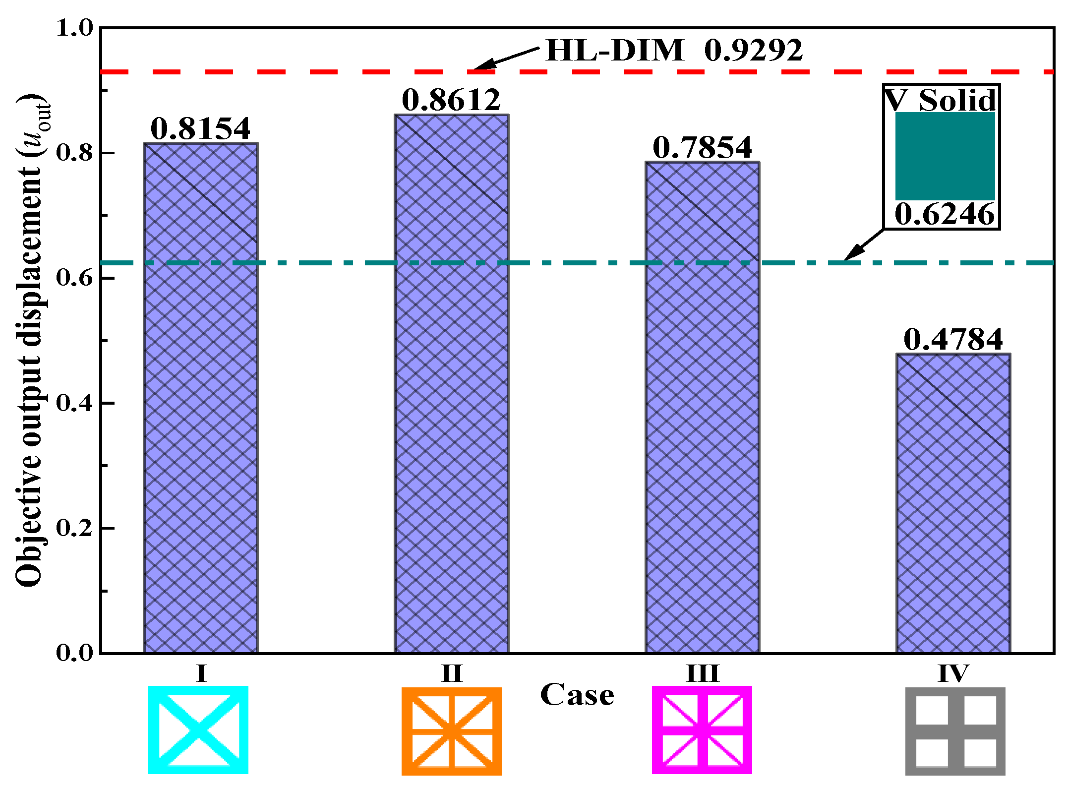
| Case | Material | Microstructures | DIM | Objective Displacement uout |
|---|---|---|---|---|
| I | OLM1 |  |  | 0.8154 |
| II | OLM2 |  |  | 0.8612 |
| III | OLM3 |  |  | 0.7854 |
| IV | OLM4 |  |  | 0.4784 |
| V | Solid |  |  | 0.6246 |
| Case | Material | Microstructures | CGM | Objective Displacement uout |
|---|---|---|---|---|
| I | ALM1 |  |  | 0.7509 |
| II | ALM2 + ALM4 |  |  | 0.8866 |
| III | ALM3 |  |  | 0.6133 |
| IV | ALM4 + ALM2 |  |  | 0.8580 |
Publisher’s Note: MDPI stays neutral with regard to jurisdictional claims in published maps and institutional affiliations. |
© 2022 by the authors. Licensee MDPI, Basel, Switzerland. This article is an open access article distributed under the terms and conditions of the Creative Commons Attribution (CC BY) license (https://creativecommons.org/licenses/by/4.0/).
Share and Cite
Wei, N.; Ye, H.; Wang, W.; Li, J.; Tian, F.; Sui, Y. Topology Optimization for Hybrid Lattice Compliant Mechanisms with Multiple Microstructures. Materials 2022, 15, 7321. https://doi.org/10.3390/ma15207321
Wei N, Ye H, Wang W, Li J, Tian F, Sui Y. Topology Optimization for Hybrid Lattice Compliant Mechanisms with Multiple Microstructures. Materials. 2022; 15(20):7321. https://doi.org/10.3390/ma15207321
Chicago/Turabian StyleWei, Nan, Hongling Ye, Weiwei Wang, Jicheng Li, Fuwei Tian, and Yunkang Sui. 2022. "Topology Optimization for Hybrid Lattice Compliant Mechanisms with Multiple Microstructures" Materials 15, no. 20: 7321. https://doi.org/10.3390/ma15207321