
Feedstock Development for Material Extrusion-Based Printing of Ti6Al4V Parts
 ,
,
Abstract
:1. Introduction
- A simple processing technique from polymer melt processing;
- Almost identical machine setups for polymers and polymer matrix composites;
- Professional and reliable FFF printers;
- Open-source FFF printers suitable for combined material–process development.
- The selection of a suitable binder system enabling good flow properties in a wide temperature range, ideally spherical fillers, and surfactants with pronounced impacts on viscosity reduction fulfilling the special needs in FFF as low pressure and a low shear-shaping method.
- Feedstock compounding with at least 50 vol% (ceramic) or 60 vol% (metal) solid loading.
- Different extrusion printing methods: filament-based FFF or pellet-based fused feedstock deposition (FFD) and derived techniques.
- Greenbody postprocessing: debinding and sintering.
2. Materials and Methods
2.1. Material Selection: Feedstock Composition
- (a)
- Stearic acid (SA, Carl Roth GmbH, Karlsruhe, Germany) as used previously;
- (b)
- PAT-77/P (E. u. P. Wuertz GmbH & Co. KG, Bingen, Germany), recommended by the vendor for MIM;
- (c)
- PAT-659/CB (E. u. P. Wuertz GmbH & Co. KG, Bingen, Germany), recommended by the vendor for MIM.
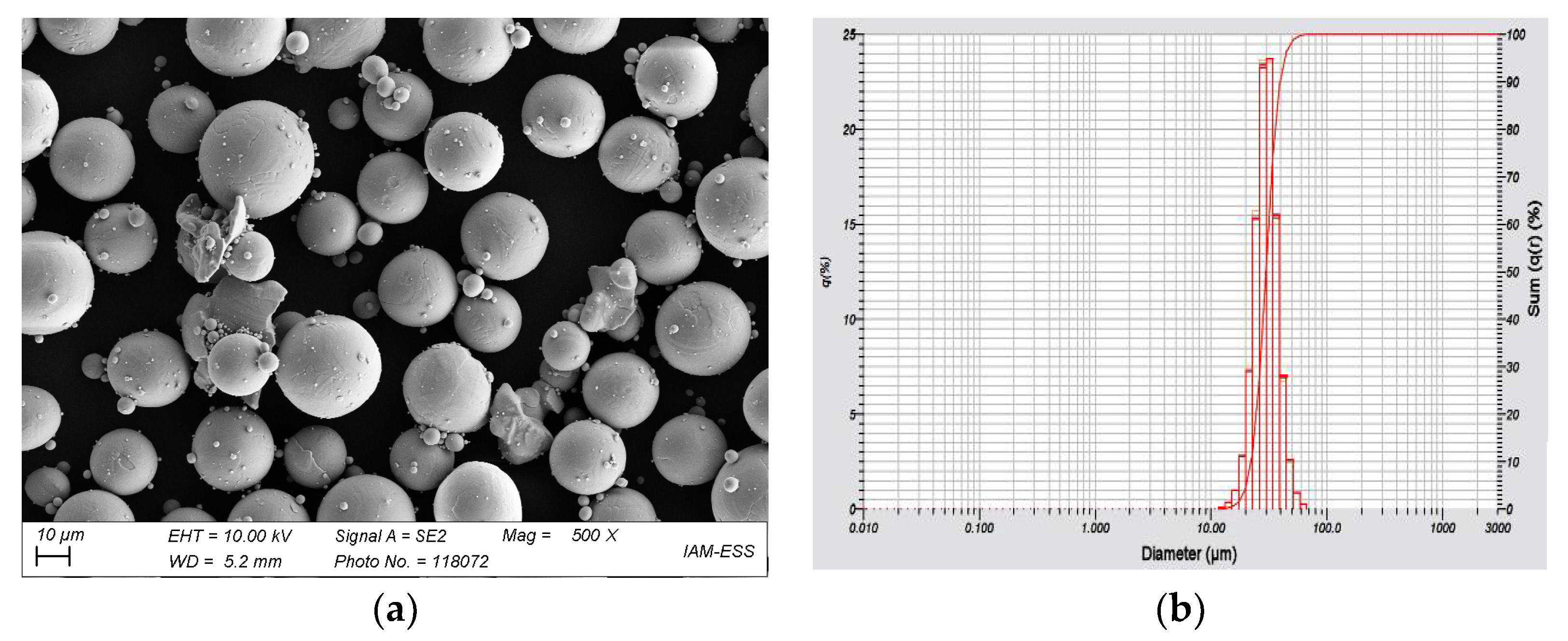
- Particle size distribution by laser diffraction (LA-950 Horiba Ltd., Kyoto, Japan);
- SSA via the BET method (Gemini VII 2390, Micromeritics Instr. Corp., Norcross, GA, USA);
- Particle density via Helium pycnometry (Pycnomatic ATC, Porotec, Germany);
- Particle morphology: SEM Supra 55 (Zeiss, Oberkochen, Germany).
2.2. Compounding
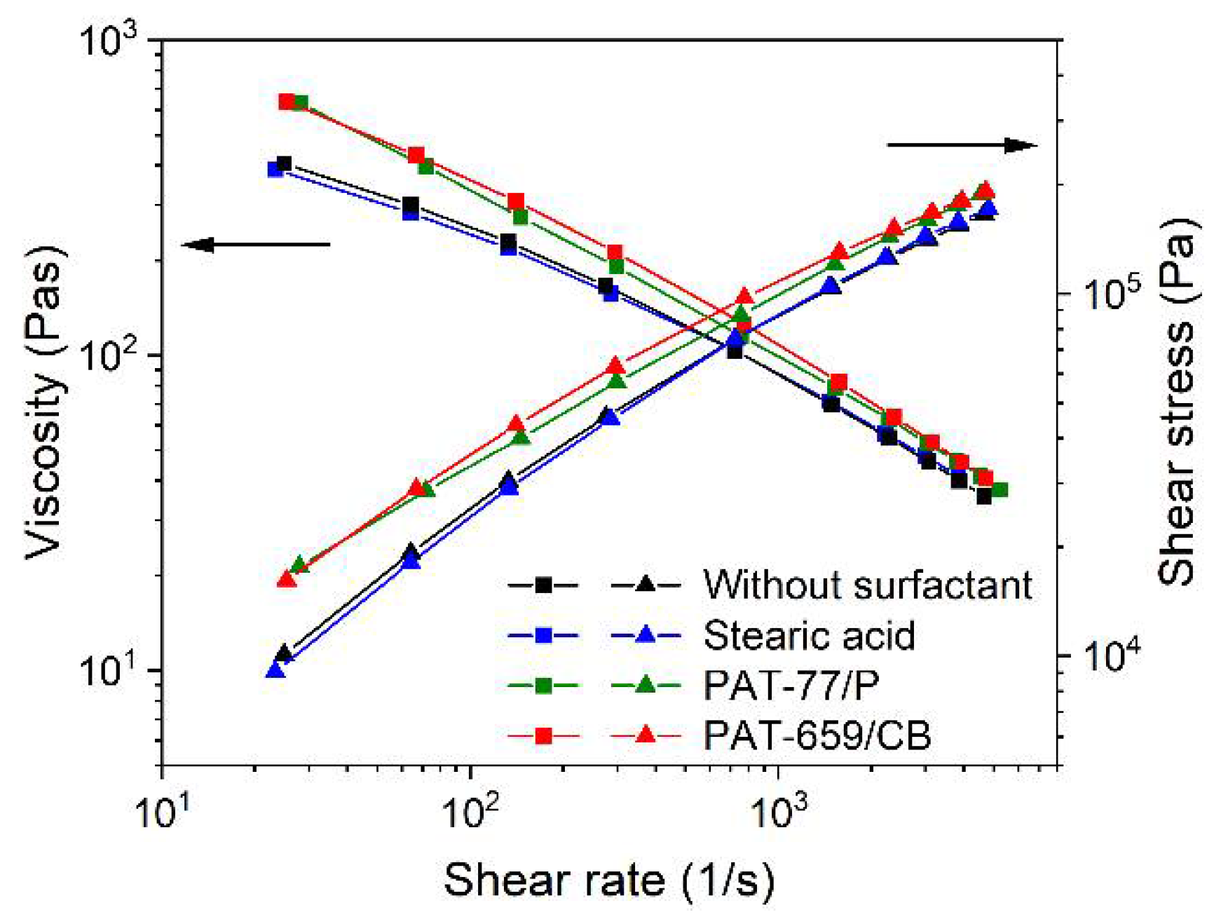
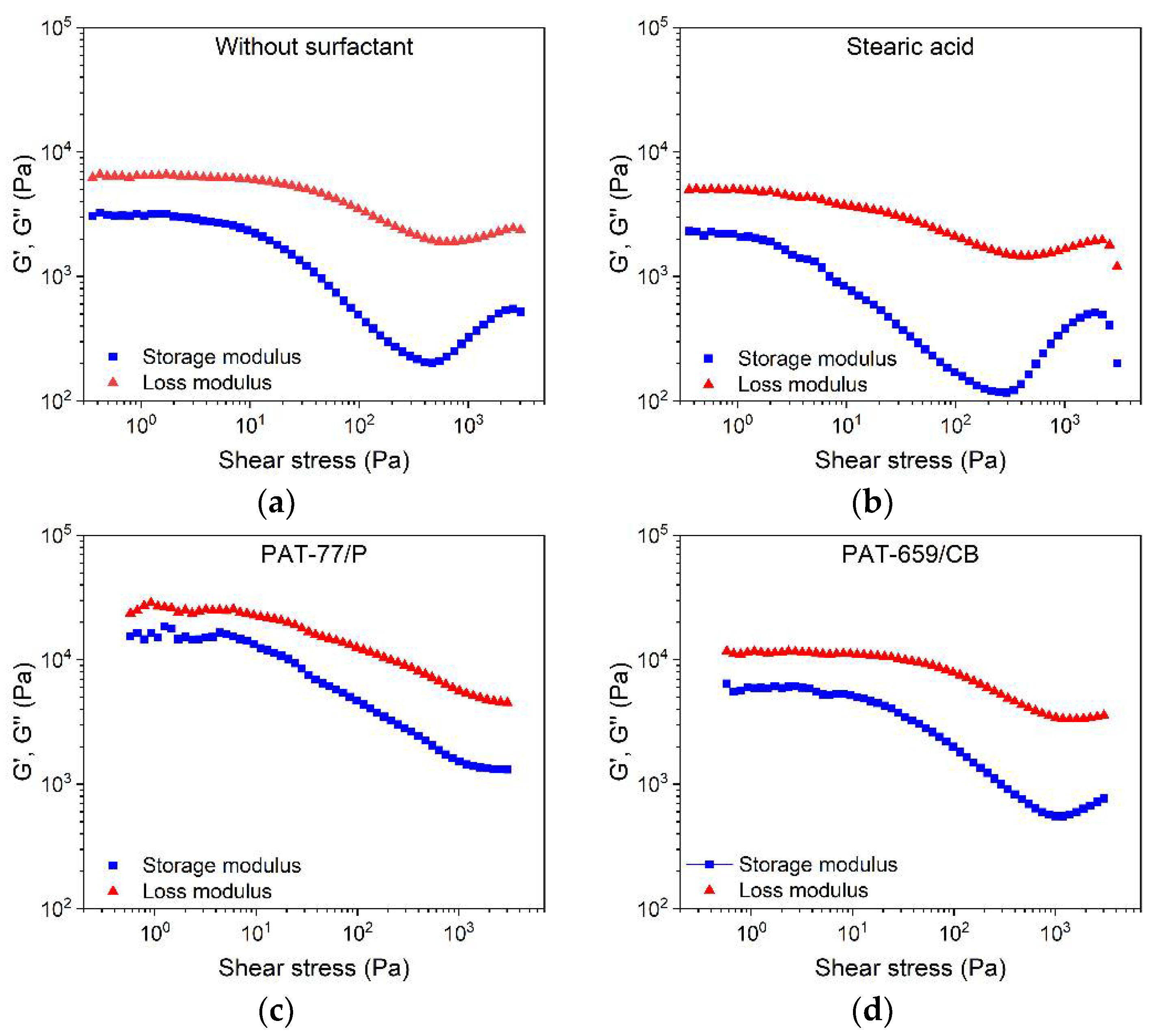
2.3. Flow Behavior
- Measuring temperature: 160 °C;
- Capillary length and diameter: 30 and 1 mm;
- Shear rate range: 1 to 5000 1/s.
- Measuring temperature: 160, 180, 200 °C;
- Shear stress: 0.01–50,000 (Pa);
- Frequency: 1 Hz;
- Pre-shearing: 0.2 1/s.
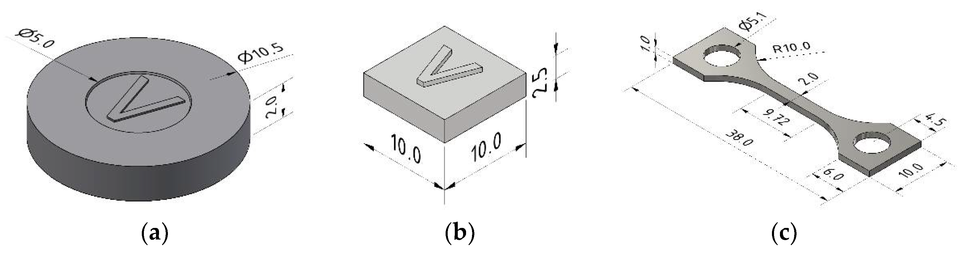
2.4. Extrusion-Based Shaping
- FFF: LDPE/wax; HDPE/LDPE/wax;
- FFD: HDPE/wax, HDPE/LDPE/wax;
- Injection molding: HDPE/wax.
2.4.1. Fused Filament Fabrication (FFF)
- Printhead: increase of the filament diameter from 1.75 to 2.85 mm;
- Installation of additional part surface ventilation;
- Covering the platform with PE-coating spring steel for better part adhesion while printing and part removal after printing;
- Usage of the Ultimaker slicer software Ultimaker Cura (V 4.10.0).
2.4.2. Fused Feedstock Deposition (FFD)
2.4.3. Metal Injection Molding
2.5. Thermal Postprocessing
2.6. Characterization
3. Results and Discussion
3.1. Material Characterization
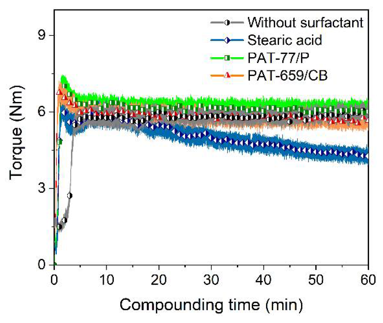
3.2. Compounding
3.2.1. LDPE/wax Binder System
- Filling phase (addition of all components into the mixing chamber);
- Mixing phase (agglomerate disruption and particle wetting);
- Equilibrium phase (the stationary state with simultaneous wetting and dewetting).
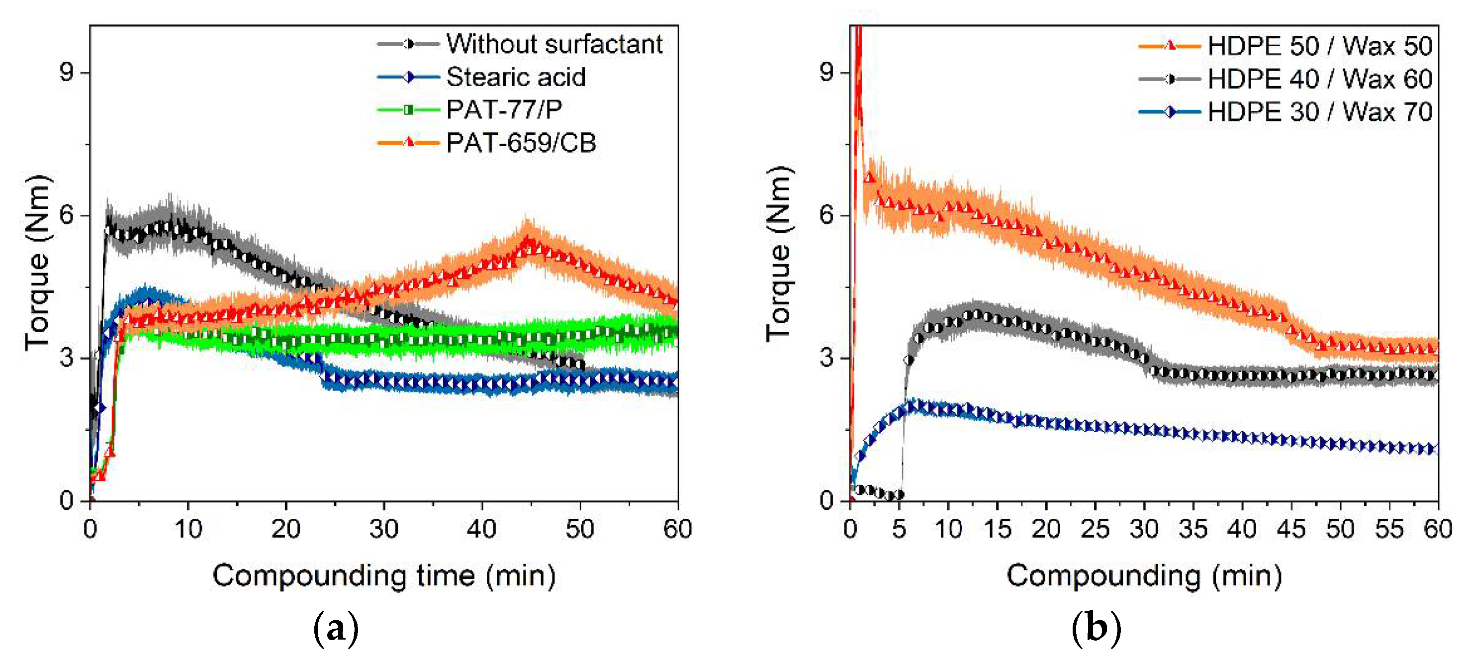
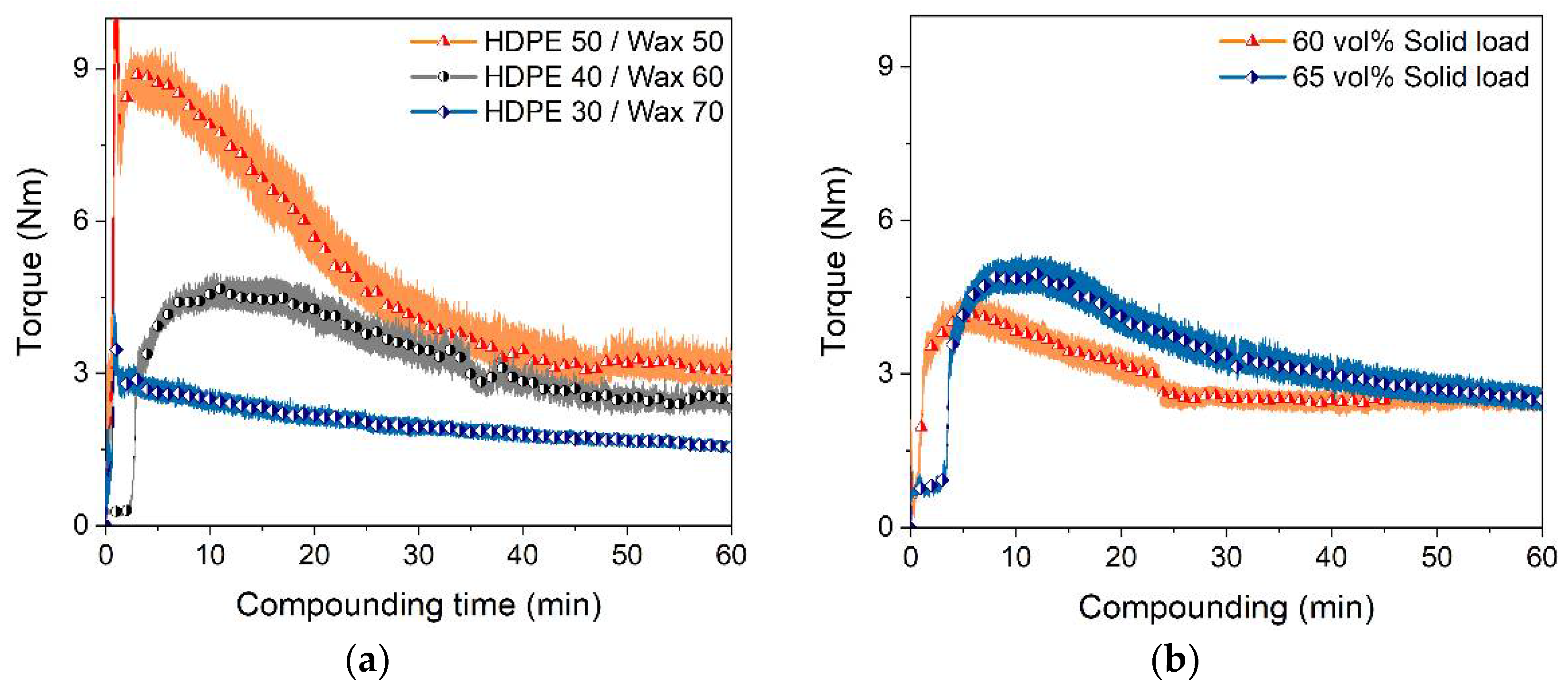
3.2.2. HDPE/Wax Binder System
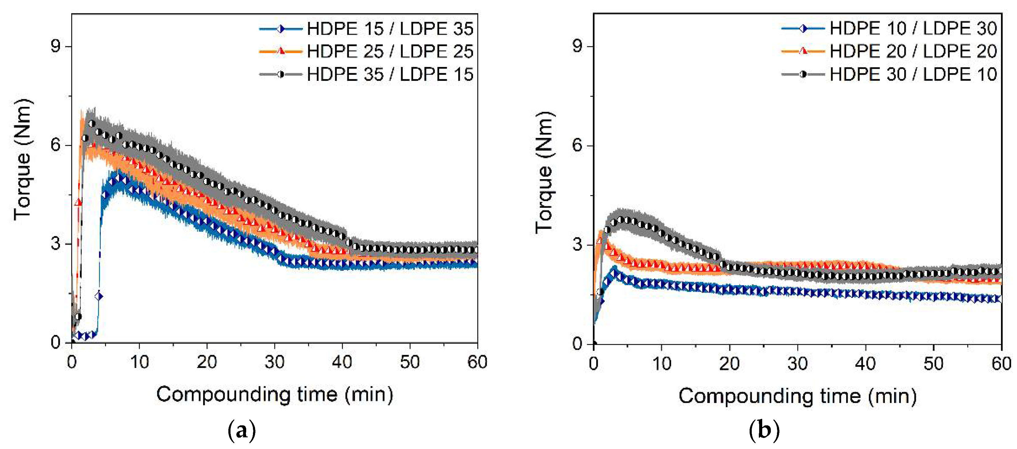
3.2.3. HDPE/LDPE/Wax Binder Systems
3.2.4. Solid Load Variation
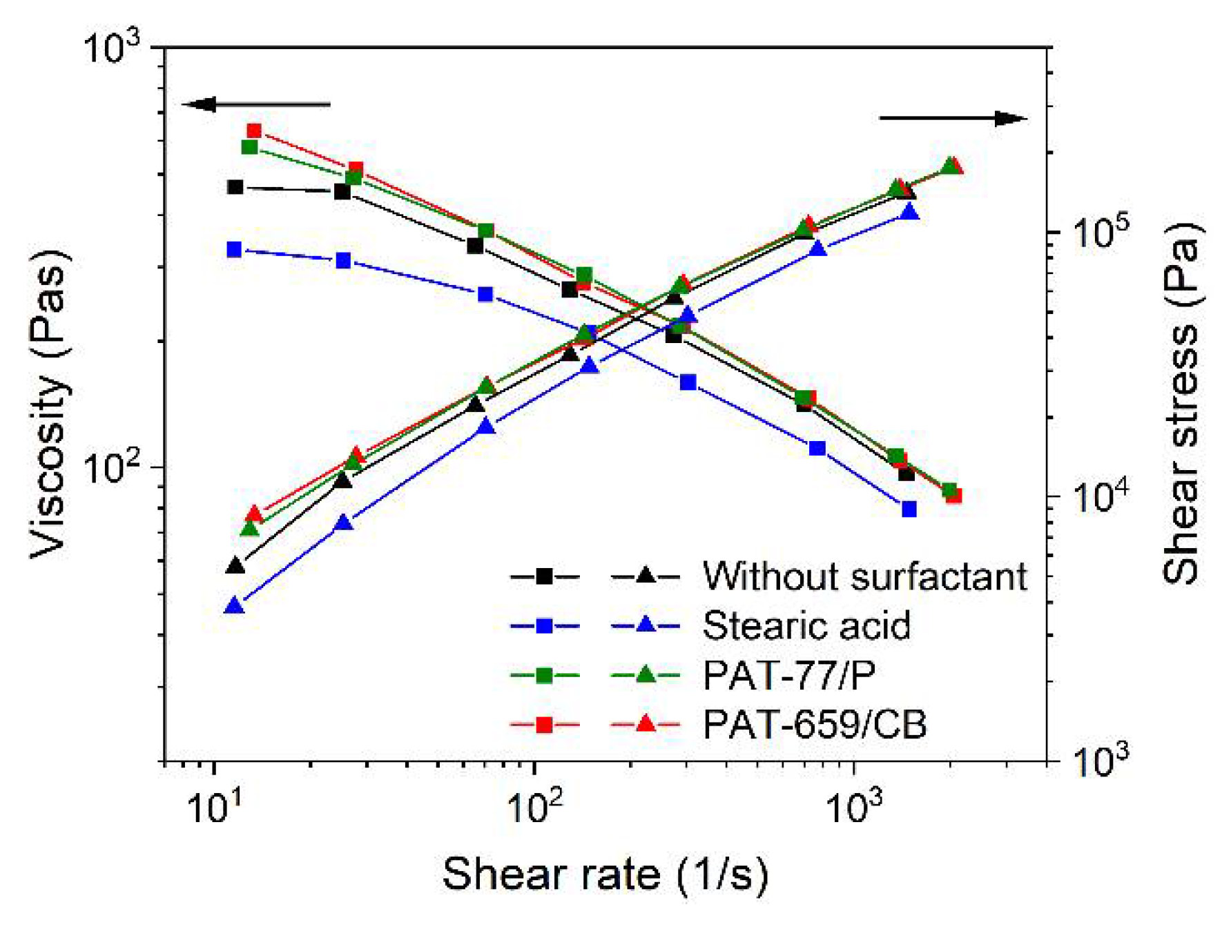
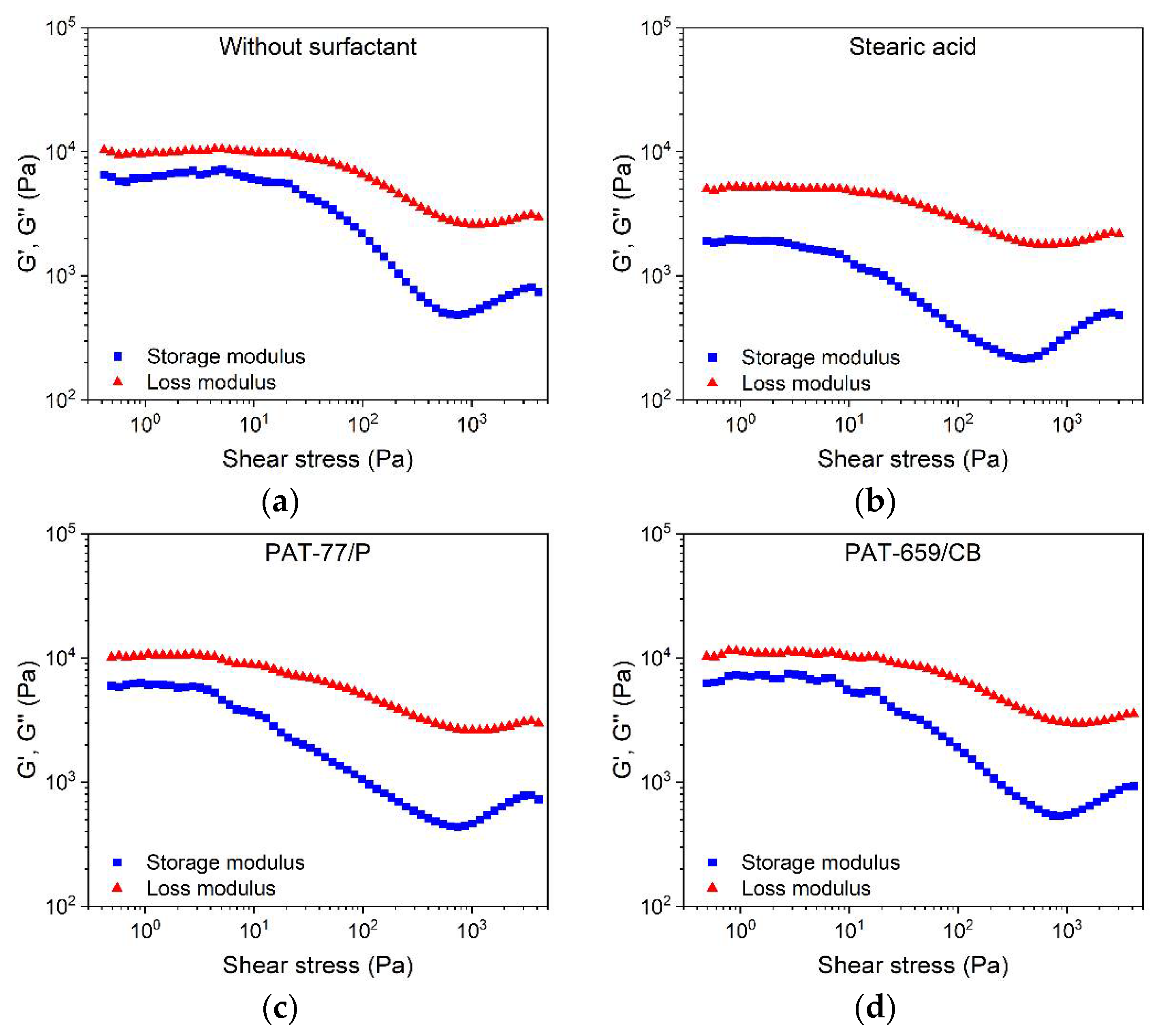
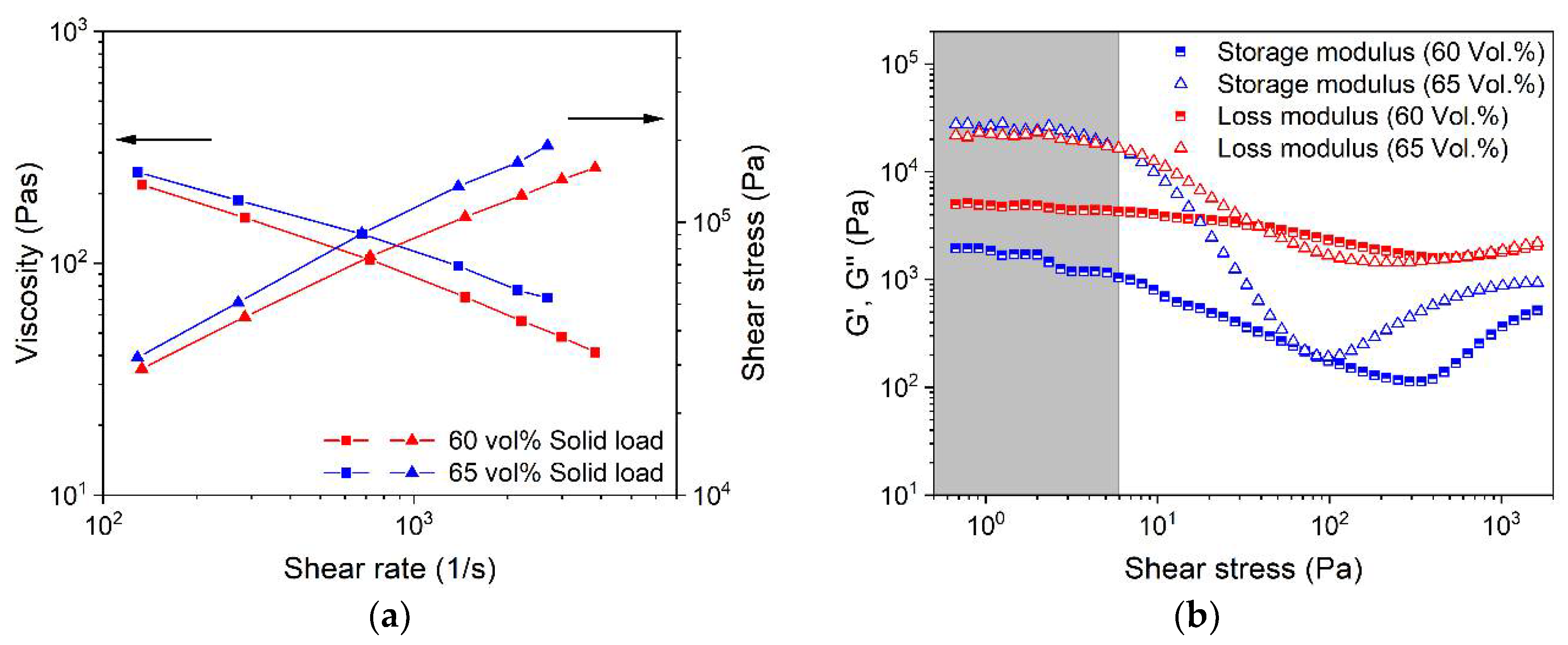
3.3. Flow Behavior
3.3.1. LDPE/Wax Binder System
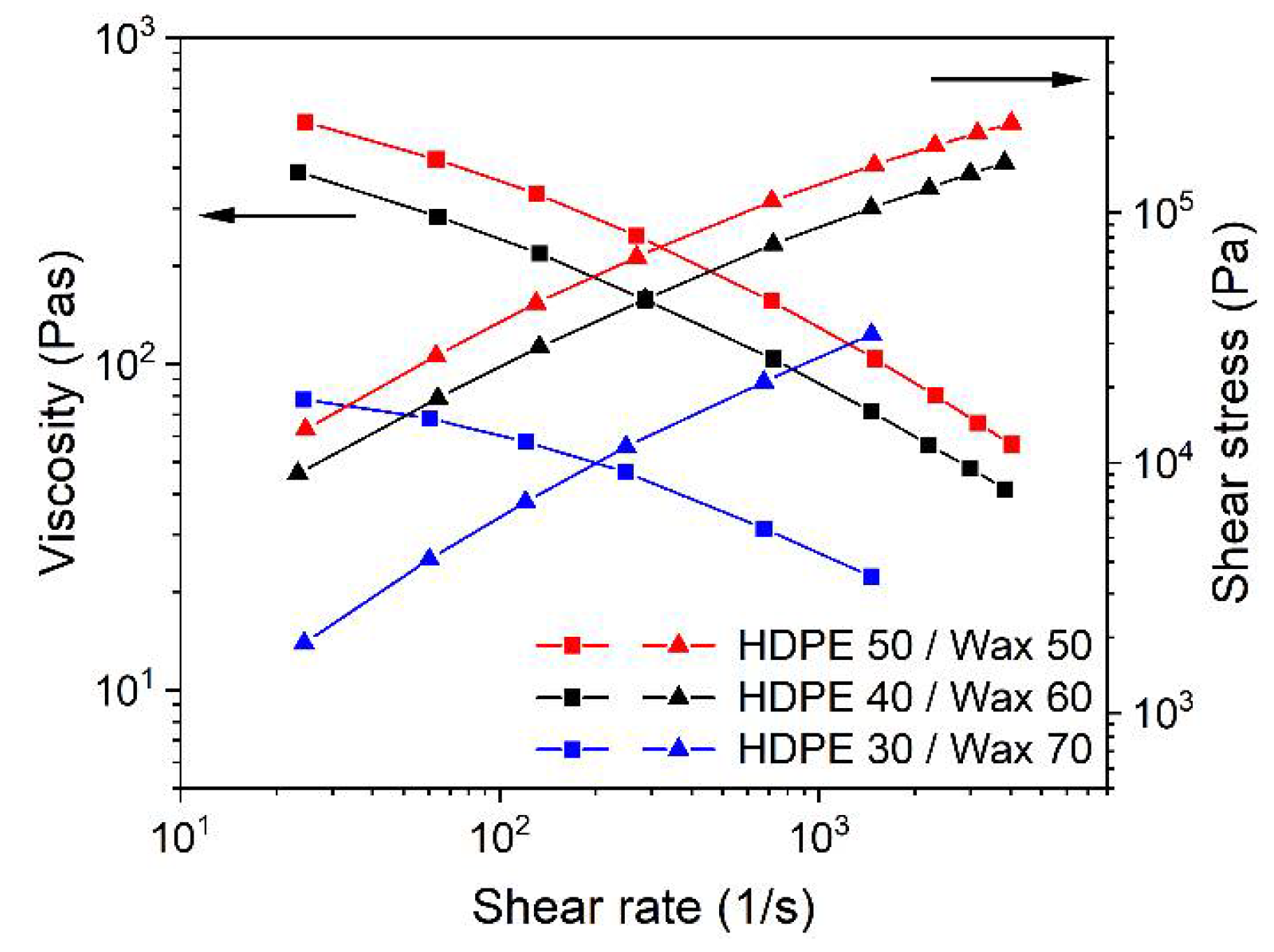
3.3.2. HDPE/Wax Binder System
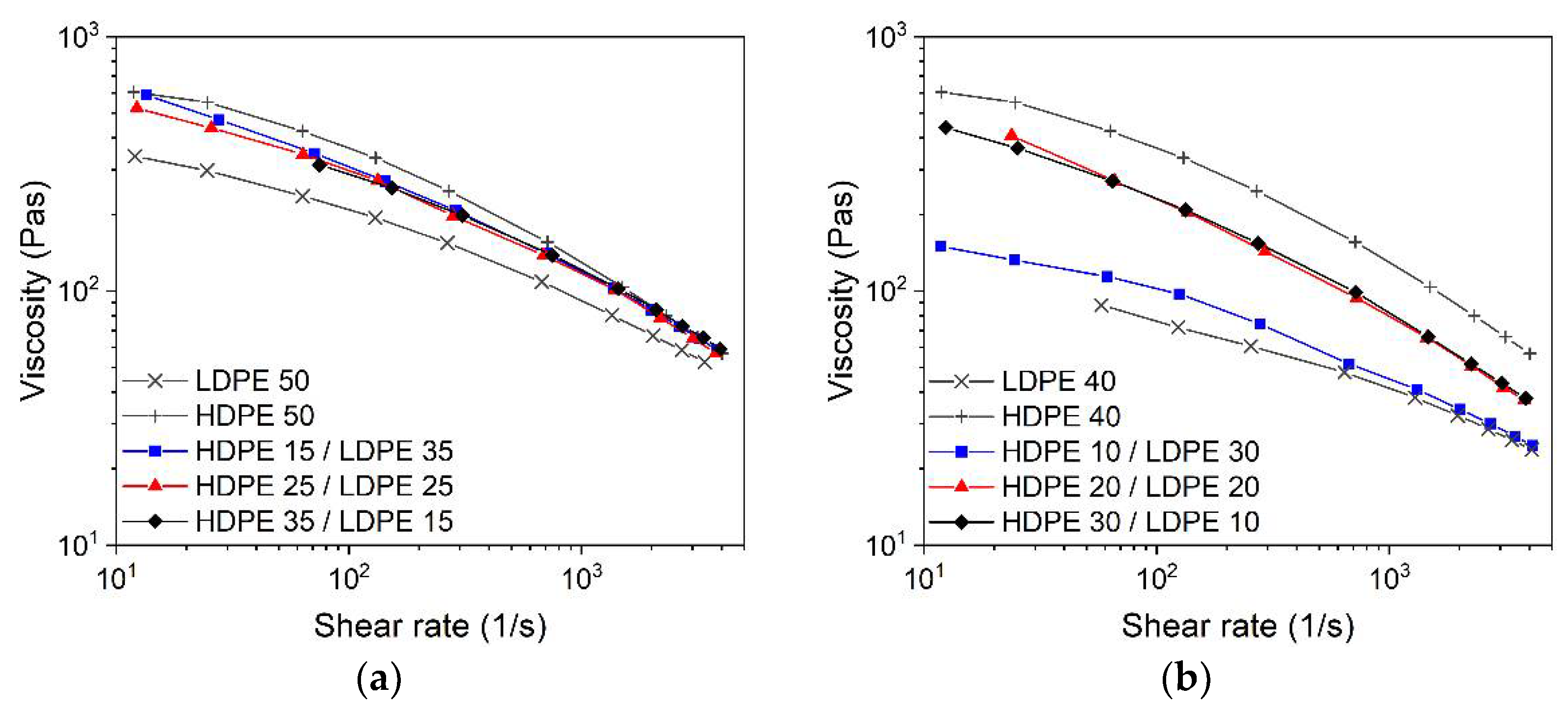
3.3.3. HDPE/LDPE/Wax Binder System
3.3.4. Solid Load Variation
3.4. Extrusion-Based Shaping
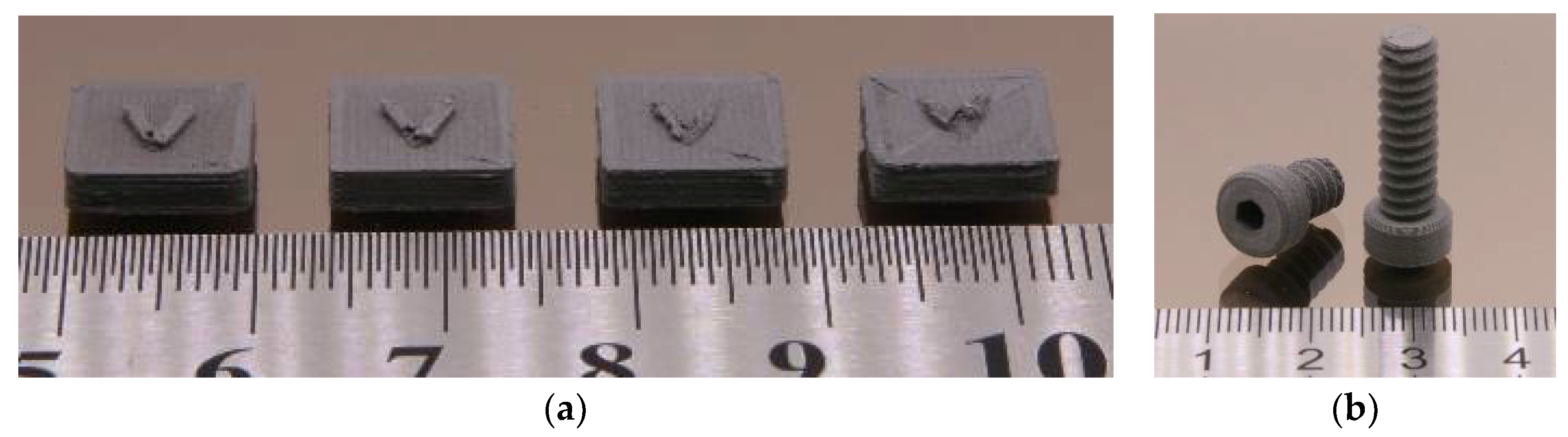
3.4.1. Fused Filament Fabrication (FFF)
- Increasing HDPE amounts led to higher extrusions temperatures;
- Huge LDPE amounts required a smaller extrusion nozzle diameter due to pronounced die swelling;
- Feedstock without LDPE could not be extruded due to enhanced brittleness;
- All feedstocks contained only SA (5 wt%) as surfactant.
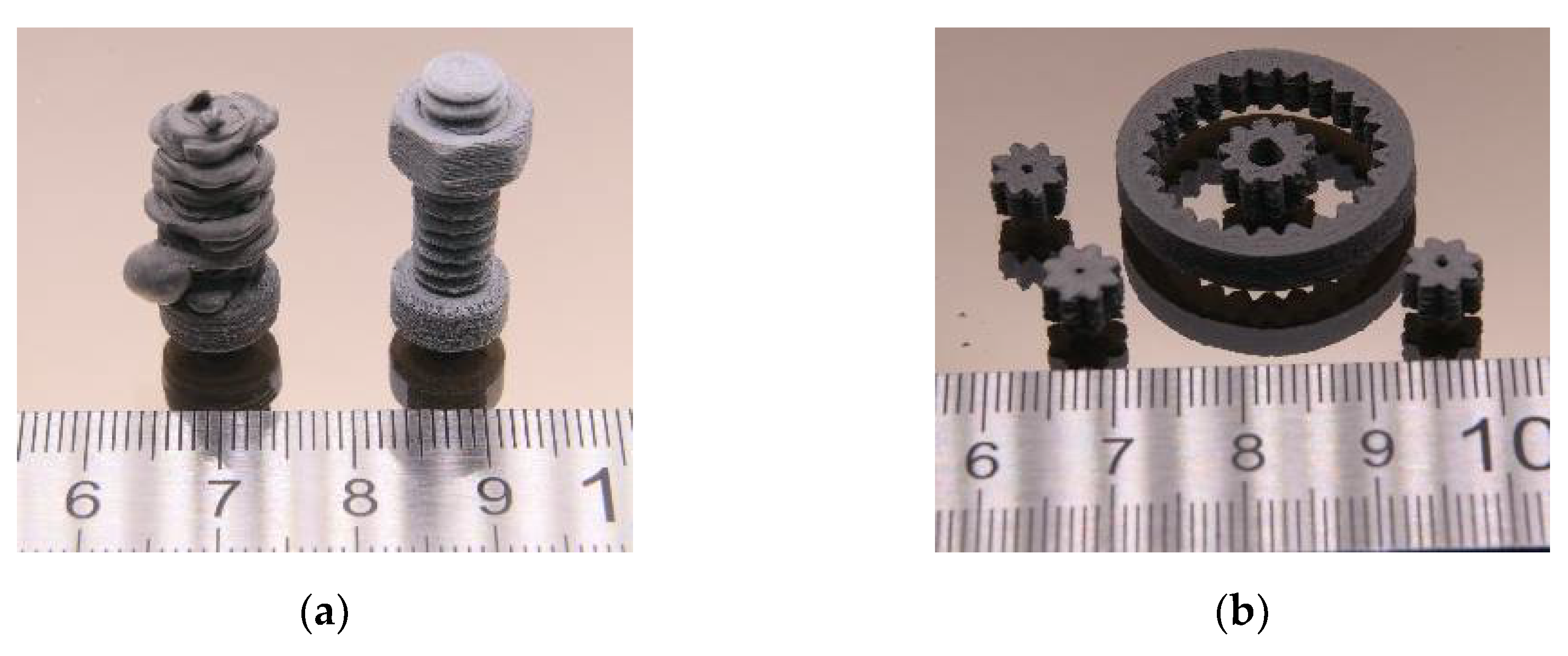
3.4.2. Fused Feedstock Deposition (FFD)
3.4.3. Metal Injection Molding
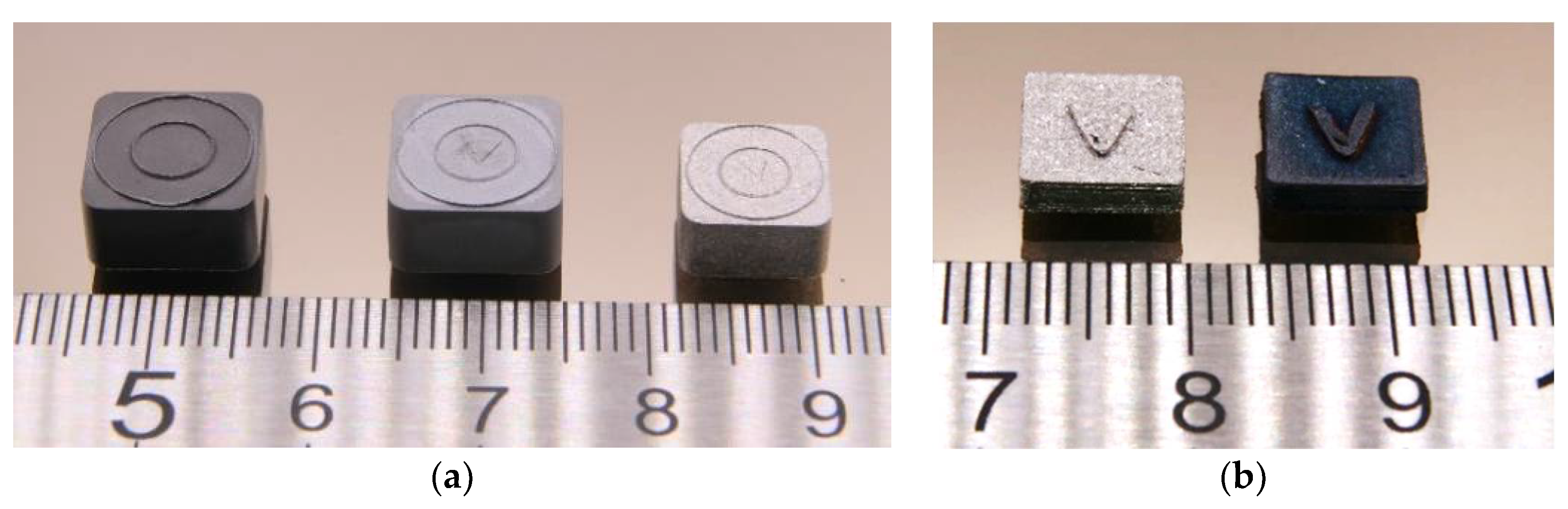
3.5. Debinding and Sintering
3.6. Characterization of Sintered Parts
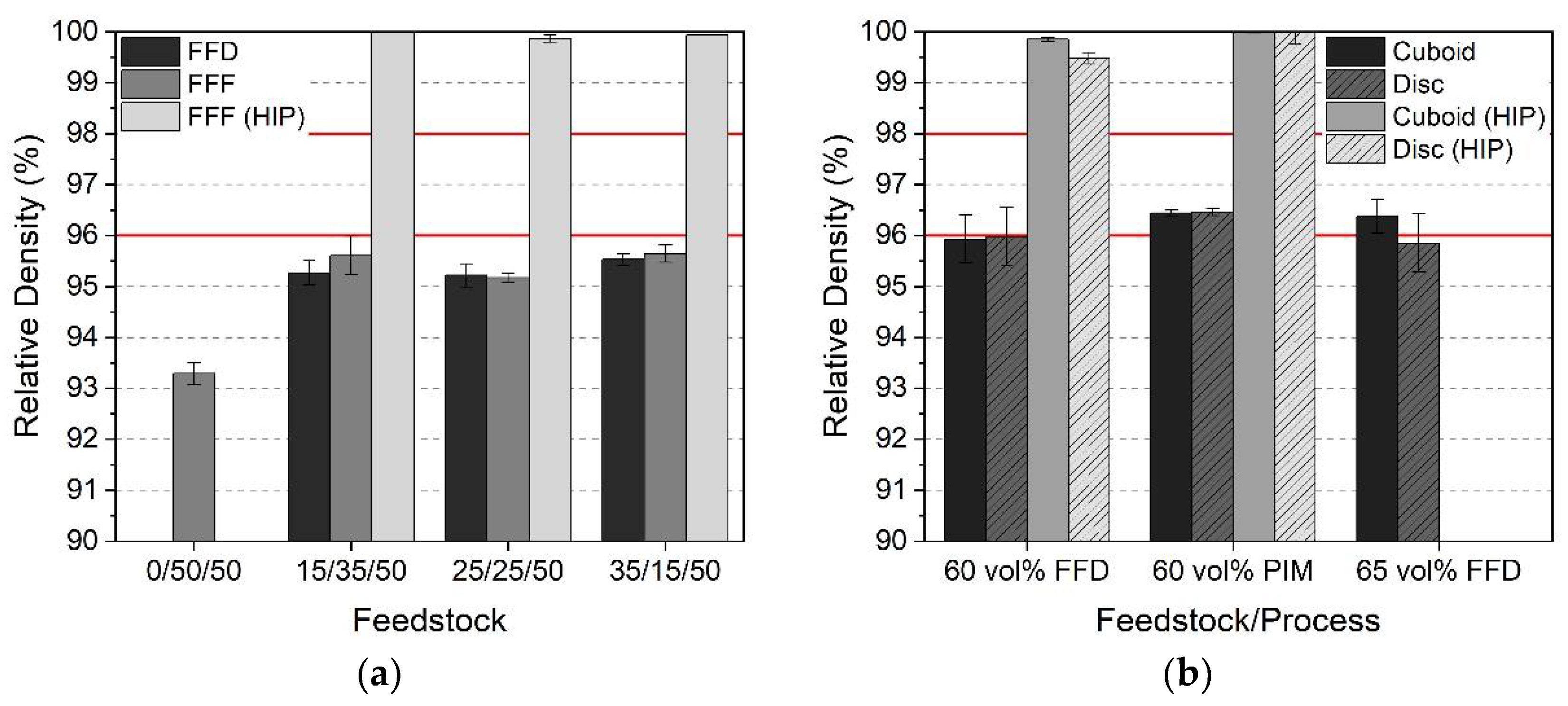
3.6.1. Part Density and Shrinkage
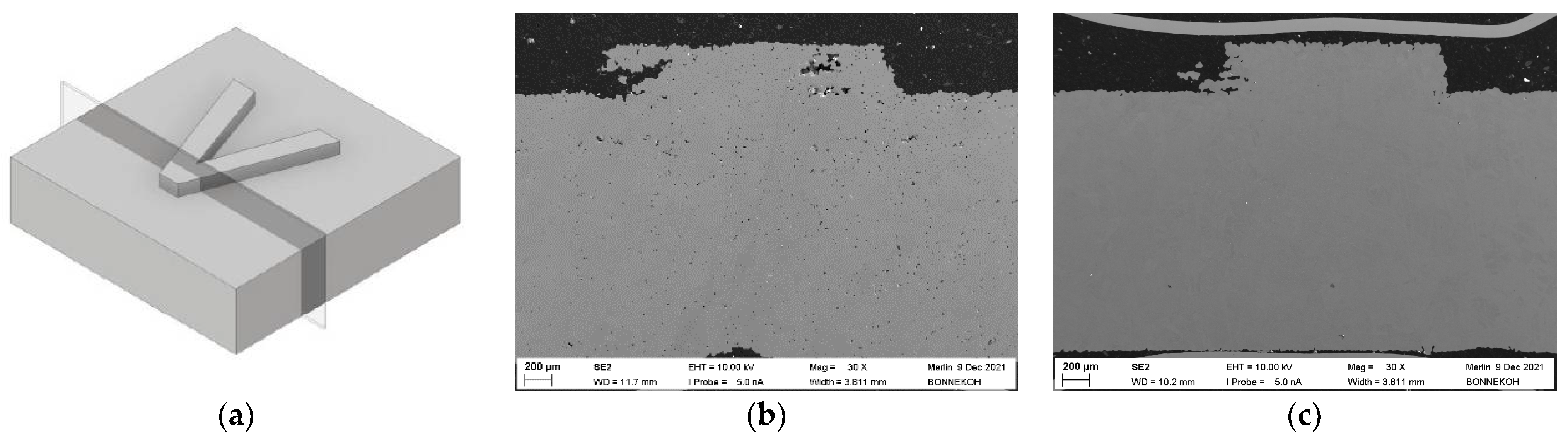
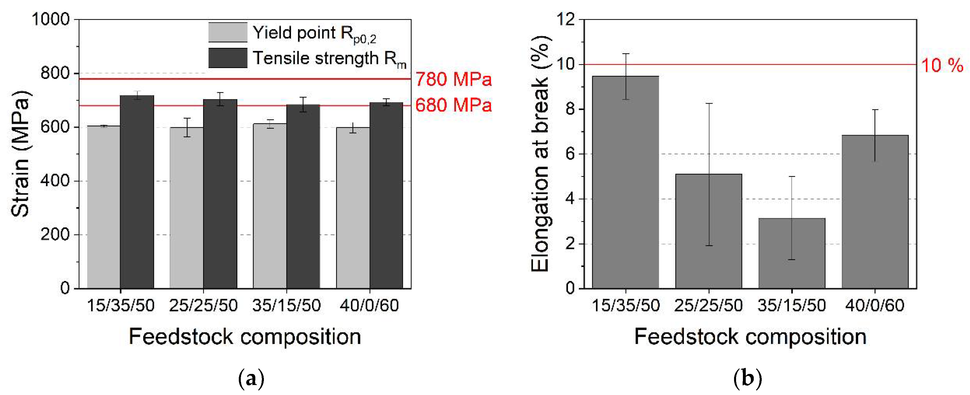
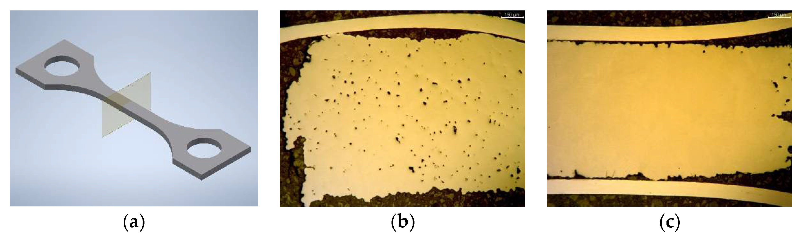
3.6.2. Microstructure and Mechanical Properties
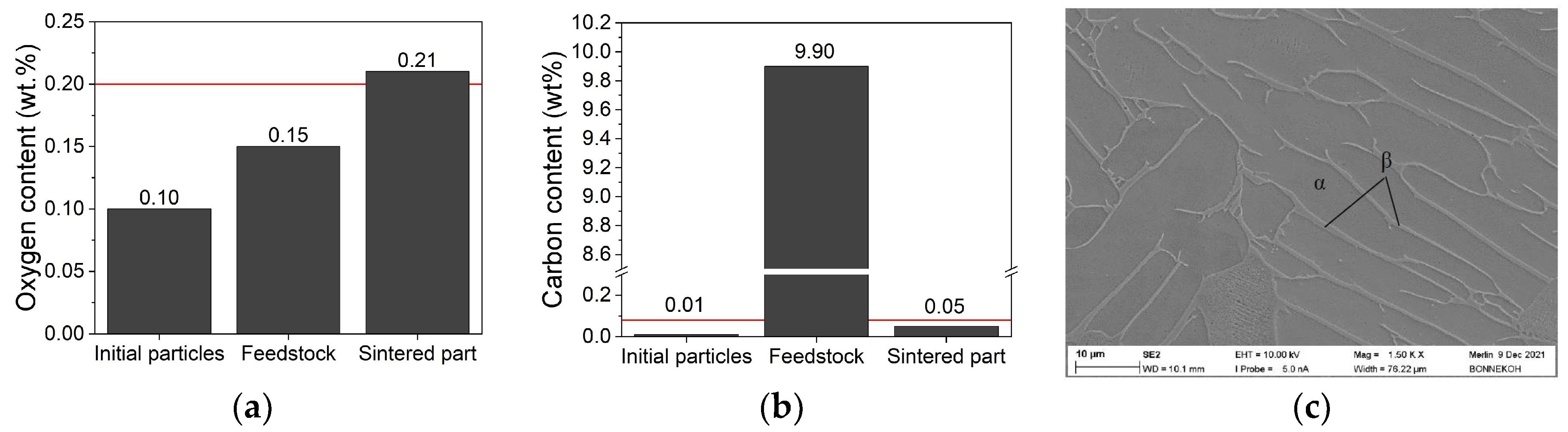
3.6.3. Elemental Analysis and Microstructure
4. Conclusions and Outlook
Author Contributions
Funding
Institutional Review Board Statement
Informed Consent Statement
Data Availability Statement
Acknowledgments
Conflicts of Interest
References
- Sarabia-Vallejos, M.A.; Rodríguez-Umanzor, F.E.; González-Henríquez, C.M.; Rodríguez-Hernández, J. Innovation in Additive Manufacturing Using Polymers: A Survey on the Technological and Material Developments. Polymers 2022, 14, 1351. [Google Scholar] [CrossRef]
- Ranjan, R.; Kumar, D.; Kundu, M.; Chandra Moi, S. A critical review on Classification of materials used in 3D printing process. Mater. Today Proc. 2022, 61, 43–49. [Google Scholar] [CrossRef]
- Cramer, C.L.; Ionescu, E.; Graczyk-Zajac, M.; Nelson, A.T.; Katoh, Y.; Haslam, J.J.; Wondraczek, L.; Aguirre, T.G.; LeBlanc, S.; Wang, H.; et al. Additive manufacturing of ceramic materials for energy applications: Road map and opportunities. J. Eur. Ceram. Soc. 2022, 42, 3049–3088. [Google Scholar] [CrossRef]
- Blakey-Milner, B.; Gradl, P.; Snedden, G.; Brooks, M.; Pitot, J.; Lopez, E.; Leary, M.; Berto, F.; du Plessis, A. Metal additive manufacturing in aerospace: A review. Mater. Des. 2021, 209, 110008. [Google Scholar] [CrossRef]
- Yadav, A.; Srivastav, A.; Singh, A.; Mushtaque, M.D.; Khan, S.A.; Kumar, H.; Arora, P.K. Investigation on the materials used in additive manufacturing: A study. Mater. Today Proc. 2021, 43, 154–157. [Google Scholar] [CrossRef]
- Saleh Alghamdi, S.; John, S.; Roy Choudhury, N.; Dutta, N.K. Additive Manufacturing of Polymer Materials: Progress, Promise and Challenges. Polymers 2021, 13, 753. [Google Scholar] [CrossRef] [PubMed]
- Pazhamannil, R.V.; Govindan, P. Current state and future scope of additive manufacturing technologies via vat photopolymerization. Mater. Today Proc. 2021, 43, 130–136. [Google Scholar] [CrossRef]
- Lakhdar, Y.; Tuck, C.; Binner, J.; Terry, A.; Goodridge, R. Additive manufacturing of advanced ceramic materials. Prog. Mater. Sci. 2021, 116, 100736. [Google Scholar] [CrossRef]
- Wang, Y.; Zhou, Y.; Lin, L.; Corker, J.; Fan, M. Overview of 3D additive manufacturing (AM) and corresponding AM composites. Compos. Part A Appl. Sci. Manuf. 2020, 139, 106114. [Google Scholar] [CrossRef]
- Singh, B.; Kumar, R.; Singh Chohan, J. Polymer matrix composites in 3D printing: A state of art review. Mater. Today Proc. 2020, 33, 1562–1567. [Google Scholar] [CrossRef]
- Yuan, S.; Shen, F.; Chua, C.K.; Zhou, K. Polymeric composites for powder-based additive manufacturing: Materials and applications. Prog. Polym. Sci. 2019, 91, 141–168. [Google Scholar] [CrossRef]
- Quanjin, M.; Rejab, M.R.M.; Idris, M.S.; Kumar, N.M.; Abdullah, M.H.; Reddy, G.R. Recent 3D and 4D intelligent printing technologies: A comparative review and future perspective. Procedia Comput. Sci. 2020, 167, 1210–1219. [Google Scholar] [CrossRef]
- Clemens, F.J.; Kerber, A. FDM/FFF an Alternative to CIM Manufacturing of Prototype and Small Quantities of Ceramic Part? Ceram Appl. 2020, 8, 27–31. [Google Scholar]
- Noetzel, D.; Eickhoff, R.; Hanemann, T. Fused Filament Fabrication of Small Ceramic Components. Materials 2018, 11, 1463. [Google Scholar] [CrossRef]
- Noetzel, D.; Hanemann, T. New Feedstock System for Fused Filament Fabrication of Sintered Alumina Parts. Materials 2020, 13, 4461. [Google Scholar] [CrossRef] [PubMed]
- Eickenscheidt, M.; Langenmair, M.; Dbouk, A.; Noetzel, D.; Hanemann, T.; Stieglitz, T. 3D-Printed Hermetic Alumina Housings. Materials 2021, 14, 200. [Google Scholar] [CrossRef]
- Cano, S.; Gonzalez-Gutierrez, J.; Sapkota, J.; Spoerk, M.; Arbeiter, F.; Schuschnigg, S.; Holzer, C.; Kukla, C. Additive manufacturing of zirconia parts by fused filament fabrication and solvent debinding: Selection of binder formulation. Addit. Manuf. 2019, 26, 117–128. [Google Scholar] [CrossRef]
- Kataoka, Y.; Yokota, K. Fabrication of Three-dimensional Zirconia Ceramics by Material Extrusion. J. Soc. Powder Technol. Jpn. 2020, 57, 520–525. [Google Scholar] [CrossRef]
- He, Q.; Jiang, J.; Yang, X.; Zhang, L.; Zhou, Z.; Zhong, Y.; Shen, Z. Additive manufacturing of dense zirconia ceramics by fused deposition modeling via screw extrusion. J. Eur. Ceram. Soc. 2021, 41, 1033–1040. [Google Scholar] [CrossRef]
- Hadian, A.; Koch, L.; Koberg, P.; Sarraf, F.; Liersch, A.; Sebastian, T.; Clemens, F. Material Extrusion Based Additive Manufacturing of Large Zirconia Structures Using Filaments with Ethylene Vinyl Acetate Based Binder Composition. Addit. Manuf. 2021, 47, 102227. [Google Scholar] [CrossRef]
- Noetzel, D.; Eickhoff, E.; Pfeifer, C.; Hanemann, T. Printing of Zirconia Parts via Fused Filament Fabrication. Materials 2021, 14, 5467. [Google Scholar] [CrossRef] [PubMed]
- Kukla, C.; Cano, S.; Moritz, T.; Müller-Köhn, A.; Courtney, P.; Hampel, S.; Holzer, C. Multimaterial Components by Material Extrusion-Fused Filament Fabrication (ME-FFF)—Production of an Infrared Heater. CFI/Ber. DKG 2019, 3, E1–E5. [Google Scholar]
- Lieberwirth, C.; Harder, A.; Seitz, H. Extrusion Based Additive Manufacturing of Metal Parts. J. Mech. Eng. Autom. 2017, 7, 79–83. [Google Scholar] [CrossRef]
- Masood, S.H.; Song, W.Q. Development of new metal/polymer materials for rapid tooling using Fused deposition modelling. Mater. Des. 2004, 25, 587–594. [Google Scholar] [CrossRef]
- Gonzalez-Gutierrez, J.; Cano, S.; Schuschnigg, S.; Kukla, C.; Sapkota, J.; Holzer, C. Additive Manufacturing of Metallic and Ceramic Components by the Material Extrusion of Highly-Filled Polymers: A Review and Future Perspectives. Materials 2018, 11, 840. [Google Scholar] [CrossRef]
- Singh, G.; Missiaen, J.-M.; Bouvard, D.; Chaix, J.-M. Copper extrusion 3D printing using metal injection moulding feedstock: Analysis of process parameters for green density and surface roughness optimization. Addit. Manuf. 2021, 38, 101778. [Google Scholar] [CrossRef]
- Kukla, C.; Gonzalez-Gutierrez, J.; Burkhardt, C.; Holzer, C. The Production of Magnets by FFF-Fused Filament Fabrication. In Proceedings of the Euro PM2017 Congress & Exhibition, Milano, Italy, 1–5 October 2017; European Powder Metallurgy Association: Chantilly, France, 2017. [Google Scholar]
- Parenti, P.; Puccio, D.; Colosimo, B.M.; Semeraro, Q. A new solution for assessing the printability of 17-4 PH gyroids produced via extrusion-based metal AM. J. Manuf. Processes 2022, 74, 557–572. [Google Scholar] [CrossRef]
- Riaz, A.; Töllner, P.; Ahrend, A.; Springer, A.; Milkereit, B.; Seitz, H. Optimization of composite extrusion modeling process parameters for 3D printing of low-alloy steel AISI 8740 using metal injection moulding feedstock. Mater. Des. 2022, 219, 110814. [Google Scholar] [CrossRef]
- ASTM F2885-17; Standard Specification for Metal Injection Molded Titanium-6Aluminum-4Vanadium Components for Surgical Implant Ap-plications. American Society for Testing and Materials International: West Conshohocken, PA, USA, 2017.
- Zhang, G.; Lu, X.; Li, J.; Chen, J.; Lin, X.; Wang, M.; Tan, H.; Huang, W. In-situ grain structure control in directed energy deposition of Ti6Al4V. Addit. Manuf. 2022, 55, 102865. [Google Scholar] [CrossRef]
- Li, H.; Yu, Y.; Li, Y.; Lin, F. Effects of the higher accelerating voltage on electron beam powder-bed based additive manufacturing of Ti6Al4V alloy. Addit. Manuf. 2022, 50, 102579. [Google Scholar] [CrossRef]
- Damon, J.; Czink, S.; Schüßler, P.; Antusch, S.; Klein, A.; Send, S.; Dapprich, D.; Dietrich, S.; Schulze, V. Mechanical surface treatment of EBM Ti6Al4V components: Effects of the resulting surface layer state on fatigue mechanisms and service life. Mater. Sci. Eng. A 2022, 849, 143422. [Google Scholar] [CrossRef]
- Zhang, F.; Wang, K.; Li, Y.; Chen, Y.; Yang, M.; Wang, M.; Clare, A.T. Composition fine-tuning for directed energy deposition of Ti-6Al-4V. J. Mater. Process. Technol. 2022, 299, 117321. [Google Scholar] [CrossRef]
- Thompson, Y.; Polzer, M.; Gonzalez-Gutierrez, J.; Kasian, O.; Heckl, J.P.; Dalbauer, V.; Kukla, C.; Felfer, P.J. Fused Filament Fabrication-Based Additive Manufacturing of Commercially Pure Titanium. Adv. Eng. Mater. 2021, 23, 2100380. [Google Scholar] [CrossRef]
- Singh, P.; Balla, V.K.; Atre, S.V.; German, R.M.; Kate, K.H. Factors affecting properties of Ti-6Al-4V alloy additive manufactured by metal fused filament fabrication. Powder Technol. 2021, 386, 9–19. [Google Scholar] [CrossRef]
- Singh, P.; Balla, V.K.; Tofangchi, A.; Atre, S.V.; Kate, K.H. Printability studies of Ti-6Al-4V by metal fused filament fabrication (MF3). Int. J. Refract. Met. Hard Mater. 2020, 91, 105249. [Google Scholar] [CrossRef]
- Gloeckle, C.; Konkol, T.; Jacobs, O.; Limberg, W.; Ebel, T.; Handge, U.A. Processing of Highly Filled Polymer-Metal Feedstocks for Fused Filament Fabrication and the Production of Metallic Implants. Materials 2020, 13, 4413. [Google Scholar] [CrossRef]
- Bek, M.; Gonzalez-Gutierrez, J.; Kukla, C.; Pušnik Črešnar, K.; Maroh, B.; Slemenik Perše, L. Rheological Behaviour of Highly Filled Materials for Injection Moulding and Additive Manufacturing: Effect of Particle Material and Loading. Appl. Sci. 2020, 10, 7993. [Google Scholar] [CrossRef]
- Rueda, M.M.; Auscher, M.-C.; Fulchiron, R.; Périé, T.; Martin, G.; Sonntag, P.; Cassagnau, P. Rheology and applications of highly filled polymers: A review of current understanding. Prog. Polym. Sci. 2017, 66, 22–53. [Google Scholar] [CrossRef]
- Mezger, T.G. The Rheology Handbook, 4th ed.; Vincentz Network: Hanover, Germany, 2014; ISBN 3-86630-650-4. [Google Scholar]
- Weber, O.; Hanemann, T. Micromanufacturing using eco-friendly metal powder injection moulding. In Proceedings of the 7th International Conference on MicroManufacturing (ICOMM 2012), Evanston, IL, USA, 11–14 March 2012. [Google Scholar]
- Piotter, V.; Hanemann, T.; Heldele, R.; Mueller, T.; Plewa, K.; Ruh, A. Metal and Ceramic Parts fabricated by Microminiature powder injection molding. Int. J. Powder Metall. 2010, 43, 21–28. [Google Scholar]
- Metal Powder Ti6Al4V, Data Sheet, Heraeus. Available online: https://www.heraeus.com/media/media/group/doc_group/products_1/additivemanufacturing/datasheets_en/Ti6Al4V.pdf (accessed on 18 July 2022).
- Clemens, H.; Mayer, S.; Heilmaier, M. Pulvermetallurgische Herstellung von innovativen Hochtemperaturwerkstoffen. BHM Berg-Und Hüttenmännische Mon. 2018, 5, 1–7. [Google Scholar] [CrossRef]
- Hanemann, T.; Heldele, R. Modern Alchemy: Ceramic Feedstock Optimization by Surfactant Screening. CFI/Ber. DKG 2010, 87, E38–E40. [Google Scholar]
- Hayat, M.D.; Wen, G.; Zulkifli, M.F.; Cao, P. Effect of PEG molecular weight on rheological properties of Ti-MIM feedstocks and water debinding behaviour. Powder Technol. 2015, 270, 293–301. [Google Scholar] [CrossRef]
- Hasib, A.G.; Niauzorau, S.; Xu, W.; Niverty, S.; Kublik, N.; Williams, J.; Chawla, N.; Song, K.; Azeredo, B. Rheology scaling of spherical metal powders dispersed in thermoplastics and its correlation to the extrudability of filaments for 3D printing. Addit. Manuf. 2021, 41, 101967. [Google Scholar] [CrossRef]
- Gregor-Svetec, D.; Leskovšek, M.; Vrabič Brodnjak, U.; Stankovič Elesini, U.; Muck, D.; Urbas, R. Characteristics of HDPE/cardboard dust 3D printable composite filaments. J. Mater. Process. Technol. 2020, 275, 116379. [Google Scholar] [CrossRef]
- Gonzalez-Gutierrez, J.; Duretek, I.; Kukla, C.; Poljšak, A.; Bek, M.; Emri, I.; Holzer, C. Models to Predict the Viscosity of Metal Injection Molding Feedstock Materials as Function of Their Formulation. Metals 2016, 6, 129. [Google Scholar] [CrossRef]
- Zhao, M.; Qiao, L.; Zheng, J.; Ying, Y.; Yu, J.; Li, W.; Che, S. Investigation of the solvent debinding in the injection molding of ZrO2 ceramics using LDEP, HDPE and wax binders. Ceram. Int. 2019, 45, 3894–3901. [Google Scholar] [CrossRef]
- German, R.M. Progress in Titanium Metal Powder Injection Molding. Materials 2013, 6, 3641–3662. [Google Scholar] [CrossRef]
- Suwanpreecha, C.; Alabort, E.; Tang, Y.T.; Panwisawas, C.; Reed, R.C.; Manonukul, A. A novel low-modulus titanium alloy for biomedical applications: A comparison between selective laser melting and metal injection moulding. Mater. Sci. Eng. A 2021, 812, 141081. [Google Scholar] [CrossRef]
- Scott Weil, K.; Nyberg, E.; Simmons, K. A new binder for powder injection molding titanium and other reactive metals. J. Mater. Processing Technol. 2006, 176, 205–209. [Google Scholar] [CrossRef]
- Chen, G.; Cao, P.; Wen, G.; Edmonds, N. Debinding behaviour of a water soluble PEG/PMMA binder for Ti metal injection moulding. Mater. Chem. Phys. 2013, 139, 557–565. [Google Scholar] [CrossRef]
- ASTM F3001-14. Standard Specification for Additive Manufacturing Titanium-6 Aluminum-4 Vanadium ELI (Extra Low Interstitial) with Powder Bed Fusion. American Society for Testing and Materials International: West Conshohocken, PA, USA, 2021.
- DIN EN ISO 5832-3:2020-11. Implants for surgery–Metallic materials–Part 3: Wrought titanium 6-aluminium 4-vanadium alloy (ISO/DIS 5832-3:2020-11). DIN: Berlin, Germany, 2020.


| Ti6Al4V | Density (g/cm³) | d10 (µm) | d50 (µm) | d90 (µm) | SSA (m²/g) |
|---|---|---|---|---|---|
| Measured | 4.4 | 22.1 | 29.9 | 39.7 | 0.15 |
| Vendors certificate | n.a. | 21.3 | 31.5 | 42.9 | n.a. |
| Feedstock Composition: HDPE/LDPE/Wax (%) | Nozzle Diameter (mm) | Extrusion Temperature (°C) |
|---|---|---|
| 0/50/50 | 2.7 | 135 |
| 15/35/50 | 2.7 | 135 |
| 25/25/50 | 2.7 | 150 |
| 35/15/50 | 2.8 | 160 |
| 50/0/50 | n.a. | n.a. |
| Printing Parameter | 0/50/50 | 15/35/50 | 25/25/50 | 35/15/50 |
|---|---|---|---|---|
| Temperature (°C) | 170 | 170 | 170 | 180 |
| Platform temperature (°C) | 60 | 60 | 60 | 60 |
| Speed (mm/s) | 5–10 | 5–10 | 5–10 | 5–10 |
| Speed first layer (mm/s) | 5 | 5 | 5 | 5 |
| Nozzle diameter (mm) | 0.3 | 0.3 | 0.3 | 0.3 |
| Infill (%) | 105 | 105 | 105 | 105 |
| Printing Parameter | 15/35/50 | 25/25/50 | 35/15/50 | 40/0/60 | 40/0/60 1 |
|---|---|---|---|---|---|
| Printing temperature (°C) Pellet preheating temperature (°C) | 160 120 | 160 120 | 170 120 | 180 120 | 190 120 |
| Platform temperature (°C) | 70 | 70 | 70 | 65 | 70 |
| Speed (mm/s) | 10 | 10 | 7.5 | 5 | 5 |
| Speed first layer (mm/s) | 2.5 | 2.5 | 2.5 | 3 | 3 |
| Nozzle diameter (mm) | 0.4 | 0.4 | 0.4 | 0.4 | 0.4 |
| Infill (%) | 105 | 105 | 105 | 105 | 105 |
| Composition | Filament (%) | Disk (%) | Cuboid (%) | Tensile Specimen (%) |
|---|---|---|---|---|
| 0/50/50 | 97.5 ± 0.3 | 96.4 ± 1.1 | 96.6 ± 1.2 | - |
| 15/35/50 | 96.8 ± 0.4 | 95.6 ± 0.8 | 95.4 ± 0.4 | 94.4 ± 0.9 |
| 25/25/50 | 95.6 ± 0.4 | 95.4 ± 0.9 | 96.1 ± 0.9 | 93.1 ± 1.7 |
| 35/15/50 | 94.3 ± 1.7 | 94.5 ± 0.7 | 94.3 ± 1.3 | 92.6 ± 1.0 |
| 40/0/60 | - | 78.1 ± 2.6 | 82.8 ± 5.2 | 71.7 ± 2.2 |
| 40/0/60 1 | - | 84.0 ± 2.3 | 90.5 ± 5.6 | 90.1 ± 6.8 |
| 40/0/60 2 | - | 88.6 ± 0.9 | 81.8 ± 0.7 | - |
Publisher’s Note: MDPI stays neutral with regard to jurisdictional claims in published maps and institutional affiliations. |
© 2022 by the authors. Licensee MDPI, Basel, Switzerland. This article is an open access article distributed under the terms and conditions of the Creative Commons Attribution (CC BY) license (https://creativecommons.org/licenses/by/4.0/).
Share and Cite
Eickhoff, R.; Antusch, S.; Baumgärtner, S.; Nötzel, D.; Hanemann, T. Feedstock Development for Material Extrusion-Based Printing of Ti6Al4V Parts. Materials 2022, 15, 6442. https://doi.org/10.3390/ma15186442
Eickhoff R, Antusch S, Baumgärtner S, Nötzel D, Hanemann T. Feedstock Development for Material Extrusion-Based Printing of Ti6Al4V Parts. Materials. 2022; 15(18):6442. https://doi.org/10.3390/ma15186442
Chicago/Turabian StyleEickhoff, Ralf, Steffen Antusch, Siegfried Baumgärtner, Dorit Nötzel, and Thomas Hanemann. 2022. "Feedstock Development for Material Extrusion-Based Printing of Ti6Al4V Parts" Materials 15, no. 18: 6442. https://doi.org/10.3390/ma15186442