Article

Mechanical Properties Enhancement of Dissimilar AA6061-T6 and AA7075-T651 Friction Stir Welds Coupled with Deep Rolling Process

by
Pisit Kaewkham
1,2,
Wasawat Nakkiew
2,3,* and
Adirek Baisukhan
2,3
1
Graduate Program in Industrial Engineering, Faculty of Engineering, Chiang Mai University, Chiang Mai 50200, Thailand
2
Department of Industrial Engineering, Faculty of Engineering, Chiang Mai University, Chiang Mai 50200, Thailand
3
Advanced Manufacturing and Management Technology Research Center (AM2Tech), Department of Industrial Engineering, Faculty of Engineering, Chiang Mai University, Chiang Mai 50200, Thailand
*
Author to whom correspondence should be addressed.
Materials 2022, 15(18), 6275; https://doi.org/10.3390/ma15186275
Submission received: 19 July 2022 / Revised: 29 August 2022 / Accepted: 6 September 2022 / Published: 9 September 2022
(This article belongs to the Special Issue Manufacturing Technology, Materials and Methods)

Abstract

:
The main purpose of this research was to enhance the mechanical properties of friction stir welds (FSW) in the dissimilar aluminum alloys 6061-T6 and 7075-T651. The welded workpiece has tensile residual stress due to the influence of the thermal conductivity of dissimilar materials, resulting in crack initiation and less fatigue strength. The experiment started from the FSW process using the 2k full factorial with the response surface methodology (RSM) and central composite design (CCD) to investigate three factors. The experiment found that the optimal rotation speed and feed rate values were 979 and 65 mm/min, respectively. Then, the post-weld heat treatment process (PWHT) was applied. Following this, the 2k full factorial was used to investigate four factors involved in the deep rolling process (DR). The experiment found that the optimal deep rolling pressure and deep rolling offset values were 300 bar and 0.2 mm, respectively. Moreover, mechanical property testing was performed with a sequence of four design types of workpieces: FSW, FSW-PWHT, FSW-DR, and FSW-PWHT-DR. It was found that the FSW-PWHT-DR workpiece had an increase in tensile strength of up to 26.29% and increase in fatigue life of up to 129.47% when compared with the FSW workpieces, as well as a maximum compressive residual stress of −414 MPa.

1. Introduction

Friction stir welding (FSW) is a method of joining aluminum alloys. It is referred to as solid-state welding because it fuses metals at temperatures lower than the melting point. FSW has strong metallurgical characteristics compared to other welding methods. There is no loss of mixed materials [1,2]. Furthermore, the technique also does not emit toxic fumes or any forms of radiation that are hazardous to operators. Currently, friction stir welding can efficiently weld the same type of aluminum alloy, which can thoroughly solve the welding quality issue, such as welds of AA6061-T6 [3], AA2024 [4], AA7075-T651 [5], AA5754 [6], etc. This is beneficial to the automotive and aerospace industries, where there is an increasing demand for AA6061 and AA7075 due to their lightweight properties relative to their strength [5,7].
However, dissimilar aluminum alloy welding is required to control the factors of the welding process accordingly. Changes in the mechanical properties and structure of metals are influenced by the heat conductivity of dissimilar materials. Throughout the weld, an uneven strength mechanism arises [8]. The workpiece has tensile residual stress because of the shrinkage following quick quenching. This represents the beginning and expansion of crack initiation and propagation. As a result, the fatigue strength performance of the workpiece is reduced [9,10]. Therefore, optimization of the welding process factor, post-weld heat treatment processes to relieve tensile residual stress, and mechanical surface treatment to increase fatigue strength are required.
A mechanical surface treatment, such as shot peening, laser shock peening, and deep rolling, is used to prevent fatigue and extend the life of a workpiece because it creates compressive residual stress on the workpiece surface due to plastic deformation. The surface structure better resists the tensile stress from the outside, which can reduce or retard the fatigue life of materials [11,12,13,14]. However, the literature revealed that the shot peening technique produces uneven roughness on the workpiece surface [15]. Laser shock peening techniques, resulting in the residual stress of asymmetrically distributed compression, have been proposed [16]. When the effectiveness of mechanical surface treatment processes is compared, deep rolling creates less surface roughness than the shot peening and laser shock peening techniques [17]. Furthermore, the deep rolling procedure generates a deeper and larger residual stress than other methods [18,19]. As a result, the deep rolling procedure is generally acknowledged and used to treat fatigue issues.
However, the deep rolling process requires precise parameter control, especially for dissimilar AA6061-T6 and AA7075-T651 welded by FSW due to differences in material properties. At present, no research has applied the FSW process followed by post-weld heat treatment and the deep rolling process to improve the mechanical properties of dissimilar AA6061-T6 and AA7075-T651 aluminum welded alloys. As a result, this research combined the friction stir welding process, post-weld heat treatment, and deep rolling process to improve the mechanical surface properties of dissimilar 6061-T6 and 7075-T651 aluminum alloys to increase the workpiece fatigue resistance and prolong the fatigue life.

2. Materials and Methods

This research used AA6061-T6 and AA7075-T651 aluminum alloys, and the chemical composition measured by the energy-dispersive X-ray fluorescence (EDXRF) method using JEOL model JSX3400R (all units in % w/w) is shown in Table 1.

2.1. Friction Stir Welding Process

From the literature review [20,21,22], the following factors in FSW are often studied: tool pin profile, welding speed, tool rotational speed, axial load, tool tilt angle, and tool material. This research chose the significant factors that directly affect the weld quality for further investigation: rotation speed, feed rate, and type of stirring tool, through the design of the 2k full factorial experiment with RSM in conjunction with CCD to find out the optimal conditions, which are shown in Table 2. The designated response was the tensile strength (MPa).
This research designated the AA6061-T6 aluminum alloy as the advancing side and the AA7075-T651 aluminum alloy as the retreating side [20]. The stirring tool rotated in a counterclockwise direction. The stirring tool was cylindrically threaded with three flat faces (3L) and a cylindrical groove (CG) made of hardened SKD61 steel, as shown in Figure 1. This research used the following aluminum plate dimensions: 3 mm thickness, 100 mm length, and 100 mm width, as shown in Figure 2. This FSW process used the Bridgeport Computer Numerical Control (CNC) machine, model VMC500, as shown in Figure 3.

2.2. Post-Weld Heat Treatment Process

Post-weld heat treatment (PWHT) was used to relieve residual stress. In the PWHT process, we used the FSW workpiece with the optimal conditions of the friction stir welding process. From the literature review [23], by studying the mechanical properties of welds of 6061-T6 and 7075-T6 aluminum alloys using a PWHT temperature of 530 °C for 4 h with aging at 140 °C for 6 h, it was discovered that the heat-treated material released residual stress, and the hardness values were evenly distributed throughout the area. Furthermore, in [7,24], the post-weld treatment process could improve the micro hardness of the fusion zone (FZ) and heat affected zone (HAZ) to the level of the original base metal (BM), and the joint strength and ductility. This research used a heat treatment furnace, model TN1000D.

2.3. Deep Rolling Process

In the deep rolling process, the FSW-PWHT workpiece was used with the optimal FSW condition. In total, 20 workpieces were designed for this experiment. From the literature review [25,26,27], the following factors in the deep rolling process are often studied: force, ball diameter, number of passes, feed rate, and rolling offset. This research chose the significant factors that are congruent with the research objectives for investigation: pressure, speed, offset, and direction, through the design of the 2k full factorial experiment, which are shown in Table 3. The designated response was the tensile strength (MPa).
The dimensions of the deep rolling area were 50 mm in width and 80 mm in length, with 2 directions of deep rolling: transverse direction, as shown in Figure 4a, and longitudinal direction, as shown in Figure 4b. An example of the deep rolling process is shown in Figure 5.

2.4. Preparing the Workpiece for Testing

Photographs of the workpiece are shown in Figure 6. The optimal parameters of the FSW and DR processes were used to create three new workpieces for each design in the sequence, as follows:
  • Only FSW was applied (FSW);
  • FSW was applied, followed by PWHT (FSW-PWHT);
  • FSW was applied, followed by the DR process (FSW-DR);
  • FSW was applied, followed by PWHT, and then the DR process (FSW-PWHT-DR).
Figure 6. Photographs of the workpieces: (a) FSW; (b) FSW-PWHT; (c) FSW-DR; (d) FSW-PWHT-DR.
Materials 15 06275 g006

2.5. Tensile Strength Testing

Tensile strength testing was conducted using a machine from LLOYD Instruments, model LR50K, at a room temperature of about 25 °C, set up with default parameters. The tensile strength workpieces were prepared according to ASTM E8. The main dimensions for this test were a 3 mm thickness, a 57 mm gauge length, and a 19 mm width.

2.6. Residual Stress Measurement

Residual stress measurement by X-ray diffraction was conducted using the cos α method. This research used a Pulstec model μ-x360. Residual stress measurement parameters are shown in Table 4. The measurement position of the residual stress was at a distance of 0, ±5, and ±20 mm from the center of the weld, as shown in Figure 7.

2.7. Fatigue Testing

According to the ASTM D6272 standard, when undertaking the four-point bending test, the workpiece used a support span of 105 mm, and the loading span was 1/3 of the support span at a distance of 35 mm, as shown in Figure 8, with a bending stress of 410 MPa [28]. The workpiece dimensions were 200 mm in length, 3 mm in thickness, and 20 mm in width, as shown in Equation (1). This research used a test frequency of 3 Hz at a room temperature of 25 °C, with a stress ratio R = 0.
σ = F L b d 2
where
  • σ = bending stress on the outer side (MPa);
  • F = load at defined point on the load deflection curve (N);
  • L = length of support span (mm);
  • b = width of test workpiece (mm);
  • d = thickness of test workpiece (mm).
Figure 8. Test workpiece details of ASTM D6272.
Materials 15 06275 g008

3. Results and Discussion

3.1. Friction Stir Welding Results

This research used the 2k full factorial with the response surface methodology (RSM) in conjunction with the central composite design (CCD) method to find out the optimal conditions. The tensile strength testing results of the workpieces are shown in Table 5.
The factors had significant effects on the tensile strength, with two main effect factors: rotation speed (R) and feed rate (F), with p-values of 0.005 and 0.001, respectively, and one interaction effect factor: rotation speed and feed rate (R*F), with a p-value of 0.003 and an R-sq of 92.31%, as shown in Figure 9 and Table 6.
This research used a regression equation in uncoded units with an R-sq (pred) of 83.19% to predict the tensile strength of the friction stir welded workpieces, as shown in Equations (2) and (3):
T = −1; Tensile = 218.66 − 1.85R + 2.46F − 8.102R*R − 7.537F*F + 3.65R*F
T = 1; Tensile = 216.42 − 2.85R + 3.80F − 8.102R*R − 7.537F*F + 3.65R*F
where
  • R = rotation speed (rpm);
  • F = feed rate (mm/min);
  • T = type of stirring tool.
This research used the response optimizer function to find out the optimal condition using the designated maximum tensile strength, as shown in Figure 10. The optimal values were a rotation speed of 979 rev/min and a feed rate of 65 mm/min, with any type of stirring tool. The maximum tensile strength of the workpiece predicted with desirability at 0.815265 was 218.9096 MPa. After that, we confirmed the optimal condition of the five workpieces and found that the tensile strength test average was 218.201 MPa.

3.2. Deep Rolling Results

This research used the 2k full factorial to find out the optimal conditions for the deep rolling process. The tensile strength testing results of the workpieces are shown in Table 7.
The factors had significant effects on the tensile strength, with two main effect factors—deep rolling pressure (P) and deep rolling offset (O)—with p-values of 0.002 and 0.003, respectively, and one interaction effect factor—deep rolling pressure and deep rolling offset (P*O)—with a p-value of 0.012 and an R-sq of 96.31%, as shown in Figure 11 and Table 8.
This research used a regression equation in uncoded units with an R-sq (pred) of 82.39% to predict the tensile strength of the deep-rolled workpieces, as shown in Equation (4):
Tensile = 234.70 + 15.66P + 14.86O + 3.01P*F + 9.85P*O − 1.85P*D − 1.43F*D + 1.76O*D + 1.89P*F*O + 3.06P*F*D − 1.33P*O*D − 1.59F*O*D + 2.10P*F*O*D − 5.06Ct Pt
where
  • P = deep rolling pressure (bar);
  • F = deep rolling speed (mm/min);
  • O = deep rolling offset (mm);
  • D = deep rolling direction.
This research used the response optimizer function to find out the optimal conditions for the deep rolling process using the designated maximum tensile strength, as shown in Figure 12. The optimal values were a deep rolling pressure of 300 bar and deep rolling speed of 1400 mm/min; any values can be used for the deep rolling offset and deep rolling direction. The maximum tensile strength of the workpiece predicted with desirability at 0.98594 was 280.6858 Mpa. After that, we confirmed the optimal condition of the five workpieces and found that the tensile strength test average was 275.567 MPa.

3.3. Tensile Strength Testing Results

A sequence of four workpiece designs was used to compare the tensile strengths, as shown in Figure 13. It was found that the tensile strength was 312.838 MPa for the 6061-T6 workpiece, 545.077 MPa for the 7075-T651 workpiece, 218.201 MPa for the FSW workpiece, 203.256 MPa for the FSW-PWHT workpiece, 228.663 MPa for the FSW-DR workpiece, and 275.567 MPa for the FSW-PWHT-DR workpiece, increasing the tensile strength by up to 26.29% when compared to the FSW workpieces that did not undergo any improvement procedures. The stress–strain curves of the workpieces are shown in Figure 14, and photographs and micrographs of the broken workpieces from tensile testing are shown in Figure 15 and Figure 16, respectively. A comparison of the tensile strengths of the workpieces is shown in Table 9. From the literature review [20,29], by investigating the tensile strength of dissimilar materials in friction stir welded joints, it was found that the tool pin profile, feed rate, and tool rotational speed were the most influential factors with significant effects on the tensile strength. The parameterization depends on the mechanical properties of the material. Rotational speeds and feed rates that are too high tend to negatively affect the welding quality, which causes the material to break quickly. On the other hand, heat-treated parts tend to have increased ductility. Following heat treatment, the deep rolling process can be applied. From the literature review [30,31], it was found that the scale of the load and the ball diameter have a significant influence on the tensile strength. In addition, Ref. [32] applied the heat treatment process in combination with the rolling process and found that the AA6056 workpiece had increased ductility and tensile strength. The generation of compressive residual stress in the stir zone (SZ) and thermo-mechanically affected zone (TMAZ) after the PWHT process tends to increase ductility and tensile strength.

3.4. Residual Stress Measurement Results

The residual stress measurement for each point and direction (transverse and longitudinal) is shown in Figure 17. Each measurement point was measured in both the transverse and longitudinal directions. The residual stress measurement results in the transverse direction are shown in Figure 18. It was found that the FSW workpiece had a maximum tensile residual stress (positive value) of +38 MPa at a distance of −20 mm from the center of the weld. When the workpiece was heat-treated and deep-rolled (FSW-PWHT-DR), the workpiece had a maximum compressive residual stress (negative value) of −414 MPa at a distance of +20 mm from the center of the weld, in addition to the remaining compressive residual stress along the entire length of the surface. The residual stress in the longitudinal direction is shown in Figure 19. It was found that the FSW-PWHT-DR workpiece had a maximum compressive residual stress of −57 MPa at a distance of −5 mm from the center of the weld, and the trend of residual stress was the same as in the transverse direction, where the compressive residual stress remained along the entire length of the surface. From the literature review [18,26,33], it was found that the tensile residual stress in the weld area remained after the welding process. This caused the workpiece to initiate a crack. When the workpiece was heated after welding, it was found that the surface residual stress was relieved, and there was a consistent distribution of residual stress throughout the weld. When the workpiece was deep-rolled (FSW-PWHT-DR), it was found that the deep rolling technique resulted in the workpiece having compressive residual stress.

3.5. Fatigue Life Results

Photographs and micrographs of the broken workpieces from fatigue life testing are shown in Figure 20 and Figure 21, respectively. The fatigue life test with a bending stress of 410 MPa is shown in Figure 22. The fatigue life was 2304 cycles for the FSW workpiece, 2534 cycles for the FSW-PWHT workpiece, 3129 cycles for the FSW-DR workpiece, and 5287 cycles for the FSW-PWHT-DR workpiece. The FSW-PWHT-DR workpiece can increase the fatigue life by up to 129.47% when compared with the FSW workpieces that did not undergo any improvement processes. A comparison of the fatigue life of the workpieces is shown in Table 10. The increase in compressive residual stress had a significant influence on the fatigue life. After the FSW process, the welded area had tensile residual stress that tended to result in low fatigue resistance. After the PWHT and DR processes, it was found that the FSW-PWHT-DR workpiece had compressive residual stress that tended to result in high fatigue resistance. In addition, the deep-rolled workpiece’s surface hardness, its surface roughness was uniformly smooth, increasing the fatigue strength [25,34,35]. The compressive residual stress produced by deep rolling tended to result in higher fatigue resistance [18,19].

3.6. Microstructure

The optical micrograph of the workpieces is shown in Figure 23. The TMAZ-AS and TMAZ-RS of the FSW, FSW-PWHT, FSW-DR, FSW-PWHT-DR, as shown in Figure 23a,c,d,f,g,i,j,l, respectively, exhibited smaller grain sizes and uniform distributions of precipitates and coarse grain size compared to SZ. The SZ of the FSW, FSW-DR, as shown in Figure 23b,h, respectively, exhibited a layer due to the different types of materials. Furthermore, the SZ of the FSW-PWHT, FSW-PWHT-DR, as shown in Figure 23e,k, respectively exhibited a marginal reduction layer due to the PWHT process. Moreover, the SZ of the FSW, FSW-PWHT, FSW-DR, FSW-PWHT-DR exhibited an equal and fine-grain size for both AA6061-T6 and AA7075-T651, as shown in Figure 24.

4. Conclusions

The main purpose of this research was to enhance the mechanical properties of friction stir welds (FSW) in the dissimilar aluminum alloys 6061-T6 and 7075-T651. Therefore, the improvement sequence started from the experiment on the optimal factor for the FSW process. After welding, the workpiece was passed through the PWHT process, and then the DR process experiment was performed on the workpiece to find out the optimal factor. Moreover, the optimal parameters of the FSW and DR processes were used to create a sequence of four design types (FSW, FSW-PWHT, FSW-DR, and FSW-PWHT-DR) for mechanical property testing. The main findings are summarized below:
  • In the friction stir welding process, it was found that the rotation speed and feed rate had significant effects on the tensile strength. The optimal values were a rotation speed of 979 rev/min and a feed rate of 65 mm/min, and any type of stirring tool can be used.
  • In the deep rolling process, it was found that the deep rolling pressure and deep rolling offset had significant effects on the tensile strength. The optimal values were a deep rolling pressure of 300 bar and deep rolling offset of 0.2 mm; the deep rolling speed and deep rolling direction can use any value.
  • The workpiece was subjected to the FSW process, followed by the PWHT process and the DR process (FSW-PWHT-DR). It had a tensile strength of 275.567 MPa and a fatigue life of 5287 cycles, which represent increases of up to 26.29% and up to 129.47%, respectively, when compared with the FSW workpieces that did not undergo any improvement processes. Additionally, the residual stress was converted to compressive residual stress in both the transverse and longitudinal directions.

Author Contributions

Conceptualization, P.K. and W.N.; methodology and experimental, P.K.; writing—original draft preparation, P.K.; writing—review and editing, W.N. and A.B.; supervision, W.N. All authors have read and agreed to the published version of the manuscript.

Funding

This research was funded by Graduate Research Scholarships (Student ID: 620631083), Chiang Mai University, Thailand and CMU Mid-Career Research Fellowship program, Chiang Mai University, Thailand, and supported by Chiang Mai University (CMU), Thailand.

Institutional Review Board Statement

Not applicable.

Informed Consent Statement

Not applicable.

Data Availability Statement

Not applicable.

Acknowledgments

The authors would like to thank the Graduate School, Chiang Mai University, Chiang Mai, Thailand, for financial support.

Conflicts of Interest

The authors declare no conflict of interest.

References

  1. Firouzdor, V.; Kou, S. Al-to-Cu Friction Stir Lap Welding. Metall. Mater Trans. A 2011, 43, 303–315. [Google Scholar] [CrossRef]
  2. Genevois, C.; Girard, M.; Huneau, B.; Sauvage, X.; Racineux, G. Interfacial Reaction during Friction Stir Welding of Al and Cu. Metall. Mater Trans. A 2011, 42, 2290–2295. [Google Scholar] [CrossRef]
  3. Jamshidi, A.H.; Serajzadeh, S. A study on natural aging behavior and mechanical properties of friction stir-welded AA6061-T6 plates. Int. J. Adv. Manuf. Technol. 2013, 71, 933–941. [Google Scholar] [CrossRef]
  4. Zhang, Z.H.; Li, W.Y.; Li, J.L.; Chao, Y.J. Effective predictions of ultimate tensile strength, peak temperature and grain size of friction stir welded AA2024 alloy joints. Int. J. Adv. Manuf. Technol. 2013, 73, 1213–1218. [Google Scholar] [CrossRef]
  5. Dong, P.; Liu, Z.; Zhai, X.; Yan, Z.; Wang, W.; Liaw, P.K. Incredible improvement in fatigue resistance of friction stir welded 7075-T651 aluminum alloy via surface mechanical rolling treatment. Int. J. Fatigue 2019, 124, 15–25. [Google Scholar] [CrossRef]
  6. Kulekci, M.K.; Şik, A.; Kaluç, E. Effects of tool rotation and pin diameter on fatigue properties of friction stir welded lap joints. Int. J. Adv. Manuf. Technol. 2006, 36, 877–882. [Google Scholar] [CrossRef]
  7. Jiwen, C.; Zhaodong, Z.; Xiaonan, D.; Gang, S.; Liming, L. A novel post-weld composite treatment process for improving the mechanical properties of AA 6061-T6 aluminum alloy welded joints. J. Manuf. Proc. 2022, 22, 15–22. [Google Scholar]
  8. Al-Moussawi, M.; Smith, A.J. Defects in Friction Stir Welding of Steel. Metal. Micro. Analy. 2018, 7, 194–202. [Google Scholar] [CrossRef]
  9. Wagner, L. Mechanical surface treatments on titanium, aluminum and magnesium alloys. Mater Sci. Eng. A 1999, 263, 210–216. [Google Scholar] [CrossRef]
  10. Baisukhan, A.; Nakkiew, W.; Pitjamit, S. Design of Experiment for Predicting Residual Stresses in Gas Tungsten Arc Welding Process. Ind. Eng. Manag. Sci. Appl. 2015, 349, 77–84. [Google Scholar]
  11. Delgado, P.; Cuesta, I.I.; Alegre, J.M.; Díaz, A. State of the art of Deep Rolling. Precision Eng. 2013, 46, 1–10. [Google Scholar] [CrossRef]
  12. Bahl, S.; Suwas, S.; Ungàr, T.; Chatterjee, K. Elucidating microstructural evolution and strengthening mechanisms in nanocrystalline surface induced by surface mechanical attrition treatment of stainless steel. Acta Mater. 2017, 122, 138–151. [Google Scholar] [CrossRef]
  13. Schulze, V. Modern Mechanical Surface Treatment, 1st ed.; Wiley-VCH: Weinheim, Germany, 2005. [Google Scholar]
  14. Hatamleh, O.; Lyons, J.; Forman, R. Laser and shot peening effects on fatigue crack growth in friction stir welded 7075-T7351 aluminum alloy joints. Int. J. Fatigue 2007, 29, 421–434. [Google Scholar] [CrossRef]
  15. Luong, H.; Hill, M.R. The effects of laser peening and shot peening on high cycle fatigue in 7050-T7451 aluminum alloy. Mater Sci. Eng. A 2010, 527, 699–707. [Google Scholar] [CrossRef]
  16. Zhan, Y.; Li, Y.; Zhang, E.; Ge, Y.; Liu, C. Laser ultrasonic technology for residual stress measurement of 7075 aluminum alloy friction stir welding. Appl. Acous. 2019, 145, 52–59. [Google Scholar] [CrossRef]
  17. Juijerm, P.; Altenberger, I. Fatigue Performance Enhancement of Steels using Mechanical Surface Treatments. J. Met. Mater Miner. 2007, 17, 59–65. [Google Scholar]
  18. Zhuang, W.; Liu, Q.; Djugum, R.; Sharp, P.K.; Paradowska, A. Deep surface rolling for fatigue life enhancement of laser clad aircraft aluminium alloy. Appl. Surf. Sci. 2014, 320, 558–562. [Google Scholar] [CrossRef]
  19. Majzoobi, G.H.; Azadikhah, K.; Nemati, J. The effects of deep rolling and shot peening on fretting fatigue resistance of Aluminum-7075-T6. Mater Sci. Eng. A 2009, 516, 235–247. [Google Scholar] [CrossRef]
  20. Raturi, M.; Garg, A.; Bhattacharya, A. Joint strength and failure studies of dissimilar AA6061-AA7075 friction stir welds: Effects of tool pin, process parameters and preheating. Eng. Fail Anal. 2019, 96, 570–588. [Google Scholar] [CrossRef]
  21. Jafari, H.; Mansouri, H.; Honarpisheh, M. Investigation of residual stress distribution of dissimilar Al-7075-T6 and Al-6061-T6 in the friction stir welding process strengthened with SiO2 nanoparticles. J. Manuf. Proc. 2019, 43, 145–153. [Google Scholar] [CrossRef]
  22. Elatharasan, G.; Kumar, V. An Experimental Analysis and Optimization of Process Parameter on Friction Stir Welding of AA 6061-T6 Aluminum Alloy using RSM. Procedia Eng. 2013, 64, 1227–1234. [Google Scholar] [CrossRef]
  23. İpekoğlu, G.; Çam, G. Effects of Initial Temper Condition and Postweld Heat Treatment on the Properties of Dissimilar Friction-Stir-Welded Joints between AA7075 and AA6061 Aluminum Alloys. Metall. Mater Trans. A 2014, 45, 3074–3087. [Google Scholar] [CrossRef]
  24. Cheng, J.; Song, G.; Zhang, Z.; Khan, M.S.; Liu, Z.; Liu, L. Improving heat-affected zone softening of aluminum alloys by in-situ cooling and post-weld rolling. J. Manuf. Proc. 2022, 306, 117639. [Google Scholar] [CrossRef]
  25. Baisukhan, A.; Nakkiew, W. Sequential Effects of Deep Rolling and Post-Weld Heat Treatment on Surface Integrity of AA7075-T651 Aluminum Alloy Friction Stir Welding. Materials 2019, 12, 3510. [Google Scholar] [CrossRef]
  26. Zapata, J.; Toro, M.; López, D. Residual stresses in friction stir dissimilar welding of aluminum alloys. J. Mater Process. Technol. 2016, 229, 121–127. [Google Scholar] [CrossRef]
  27. Beghini, M.; Bertini, L.; Monelli, B.D.; Santus, C.; Bandini, M. Experimental parameter sensitivity analysis of residual stresses induced by deep rolling on 7075-T6 aluminium alloy. Surf. Coat Technol. 2014, 254, 175–186. [Google Scholar] [CrossRef]
  28. Zhang, T.; Zhang, T.; He, Y.; Fan, X.; Bi, Y. Probabilistic model of the fatigue life of epoxy-coated aluminum alloys considering atmospheric exposure. Int. J. Fatigue 2022, 162, 106899. [Google Scholar]
  29. Uyyala, S.B.; Pathri, S. Investigation of tensile strength on friction stir welded joints of dissimilar aluminum alloys. Mater. Today Proc. 2019, 23, 469–473. [Google Scholar] [CrossRef]
  30. Denkena, B.; Grove, T.; Breidenstein, B.; Abrão, A.M.; Mörke, K. Correlation between process load and deep rolling induced residual stress profiles. Procedia CIRP 2018, 78, 161–165. [Google Scholar] [CrossRef]
  31. Majzoobi, G.H.; Jouneghani, F.Z.; Khademi, E. Experimental and numerical studies on the effect of deep rolling on bending fretting fatigue resistance of Al7075. Int. J. Adv. Manuf. Technol. 2015, 82, 2137–2140. [Google Scholar] [CrossRef]
  32. Zhao, J.R.; Hung, F.Y.; Chen, B.J. Effects of heat treatment on a novel continuous casting direct rolling 6056 aluminum alloy: Cold rolling characteristics and tensile fracture properties. J. Mater Res. Technol. 2021, 11, 535–547. [Google Scholar] [CrossRef]
  33. Sun, T.; Roy, M.J.; Strong, D.; Withers, P.J.; Prangnell, P.B. Comparison of residual stress distributions in conventional and stationary shoulder high-strength aluminum alloy friction stir welds. J. Mater Process. Technol. 2017, 242, 92–100. [Google Scholar] [CrossRef]
  34. Muñoz-Cubillos, J.; Coronado, J.; Rodríguez, S.A. Deep rolling effect on fatigue behavior of austenitic stainless steels. Int. J. Fatigue 2017, 95, 120–131. [Google Scholar] [CrossRef]
  35. Prabhu, P.R.; Kulkarni, S.M.; Sharma, S.S. Influence of deep cold rolling and low plasticity burnishing on surface hardness and surface roughness of AISI 4140 steel. World Acad. Eng. Technol. 2010, 4, 1420–1425. [Google Scholar]
Figure 1. Cylindrically threaded tool with three flat faces (3L) and a cylindrical groove (CG).
Materials 15 06275 g001
Figure 2. Aluminum plates: (a) AA6061-T6; (b) AA7075-T651.
Materials 15 06275 g002
Figure 3. Friction stir welding process.
Materials 15 06275 g003
Figure 4. Deep rolling direction: (a) transverse direction and (b) longitudinal direction.
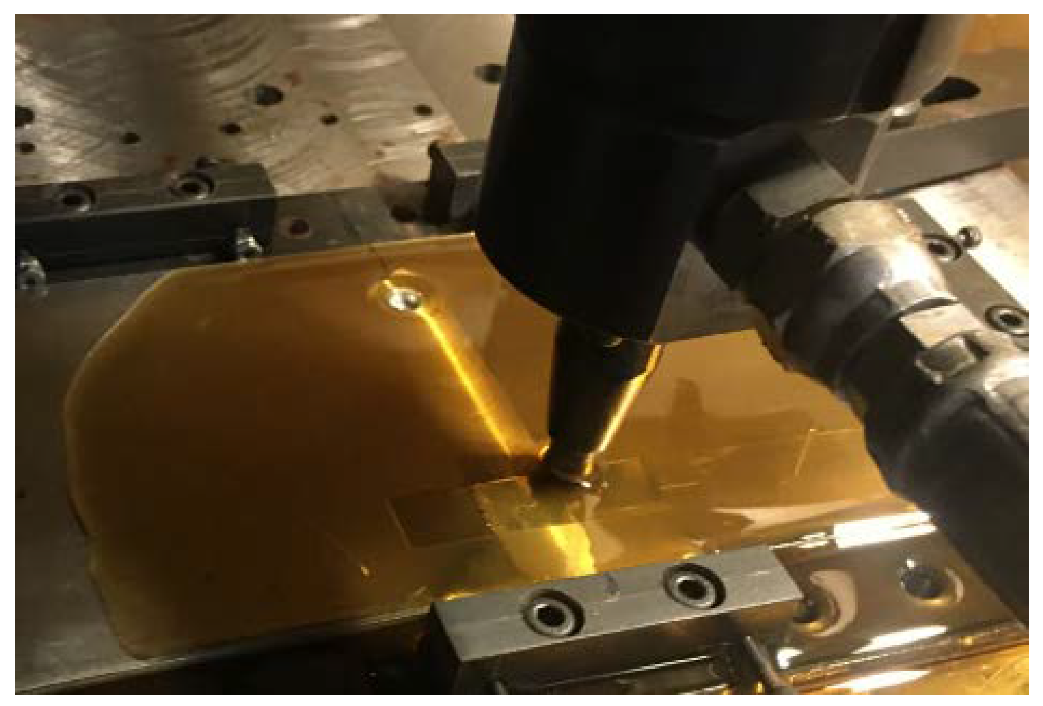
Materials 15 06275 g004
Figure 5. Deep rolling process.
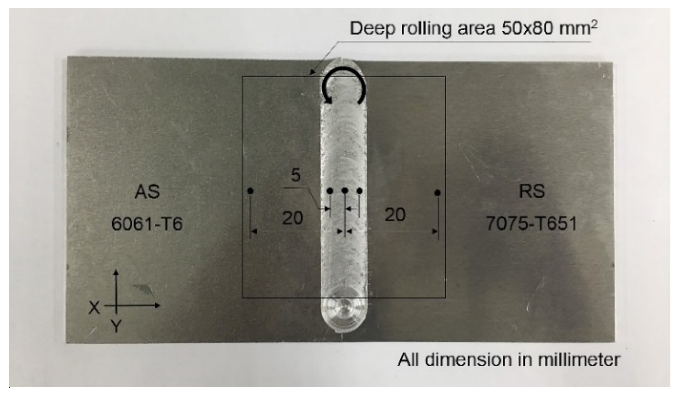
Materials 15 06275 g005
Figure 7. Residual stress measurement position.
Materials 15 06275 g007
Figure 9. Pareto chart of the standardized effects for friction stir welding.
Materials 15 06275 g009
Figure 10. Optimization plot for friction stir welding.
Materials 15 06275 g010
Figure 11. Pareto chart of the standardized effects for deep rolling.
Materials 15 06275 g011
Figure 12. Optimization plot for deep rolling.
Materials 15 06275 g012
Figure 13. Tensile strength of the workpieces.
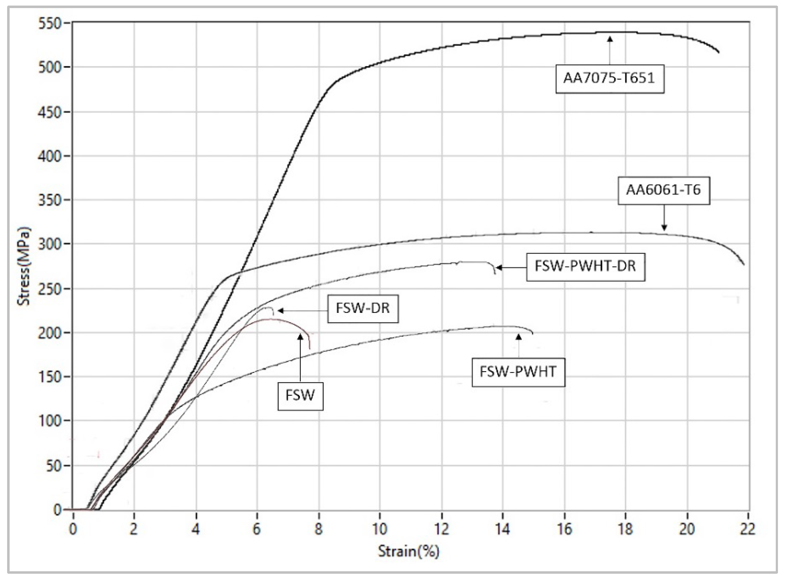
Materials 15 06275 g013
Figure 14. Stress–strain curves of the workpieces.
Materials 15 06275 g014
Figure 15. Photographs of the broken workpieces from tensile testing: (a) FSW; (b) FSW-PWHT; (c) FSW-DR; (d) FSW-PWHT-DR.
Materials 15 06275 g015
Figure 16. Micrographs of the broken workpieces from tensile testing: (a) FSW; (b) FSW-PWHT; (c) FSW-DR; (d) FSW-PWHT-DR.
Materials 15 06275 g016
Figure 17. Residual stress measurement for each point: (a) transverse direction and (b) longitudinal direction.
Materials 15 06275 g017
Figure 18. Residual stress in the transverse direction.
Materials 15 06275 g018
Figure 19. Residual stress in the longitudinal direction.
Materials 15 06275 g019
Figure 20. Photographs of the broken workpieces from fatigue life testing: (a) FSW; (b) FSW-PWHT; (c) FSW-DR; (d) FSW-PWHT-DR.
Materials 15 06275 g020
Figure 21. Micrographs of the broken workpieces from fatigue life testing: (a) FSW; (b) FSW-PWHT; (c) FSW-DR; (d) FSW-PWHT-DR.
Materials 15 06275 g021
Figure 22. Fatigue life of the workpieces.
Materials 15 06275 g022
Figure 23. Microstructure of the workpieces: (a) TMAZ-AS of FSW; (b) SZ of FSW; (c) TMAZ-RS of FSW; (d) TMAZ-AS of FSW-PWHT; (e) SZ of FSW-PWHT; (f) TMAZ-RS of FSW-PWHT; (g) TMAZ-AS of FSW-DR; (h) SZ of FSW-DR; (i) TMAZ-RS of FSW-DR; (j) TMAZ-AS of FSW-PWHT-DR; (k) SZ of FSW-PWHT-DR; (l) TMAZ-RS of FSW-PWHT-DR.
Materials 15 06275 g023
Figure 24. Microstructure of the stir zone (SZ) at 500× (a) FSW; (b) FSW-PWHT; (c) FSW-DR; (d) FSW-PWHT-DR.
Materials 15 06275 g024
Table 1. The chemical composition of AA6061-T6 and AA7075-T651 aluminum alloys.
ElementsAlMgSiFeCuCrZnMnTi
6061-T698.281.010.630.440.250.110.200.070.02
7075-T65182.503.501.390.262.330.309.200.080.00
Table 2. Friction stir welding experiments designed using factors, levels, and symbols.
No.FactorUnitSymbolLevel
−1.414−10+1+1.414
1Rotation speedrpmR576700100013001424
2Feed ratemm/minF18306090102
3Type of stirring tool-T-3L-CG-
Table 3. Deep rolling process experiments were designed using factors, levels, and symbols.
No.FactorUnitSymbolLevel
−101
1Rolling pressurebarP100200300
2Rolling speedmm/minF100012001400
3Rolling offsetmmO0.10.150.2
4Rolling direction-Dtransverse-longitudinal
Table 4. Residual stress measurement parameter.
Residual Stress Parameter ItemsProcess Parameter Values
X-ray tubeCr-Kα
X-ray detectorFull 2D detector captures the complete Debye ring (visual analysis)
Technique for analysisCos α (single position of detector)
Calculation crystal planeAl (311)
Lattice constant (a)4.0494 (Å)
Diffraction plane (h, k, l)311 (FCC)
Collimator size2 mm
Young’s modulus263.310 GPa
Poisson ratio0.34
139.497°
Table 5. Tensile strength test of friction stir welding workpiece.
Std OrderRun OrderCenter PtBlocksFactorTensile Strength (MPa)
Rotation Speed (rpm)Feed Rate (mm/min)Type of Stirring Tool
1111−1−1−1204.726
22111−1−1191.497
3311−11−1205.573
64111−11189.399
950100−1220.482
7611−111208.857
471111−1209.443
8811111207.200
10901001216.121
51011−1−11203.186
121101001215.764
11120100−1221.010
1713−1101.41421−1201.211
2014−1101.414211205.324
221501001214.870
1916−110−1.414211200.437
1517−111.414210−1200.647
211801001214.678
24190100−1220.646
1420−11−1.4142101201.543
1621−11−1.414210−1204.470
25220100−1220.426
1323−111.4142101196.352
1824−110−1.41421−1200.567
262501001214.654
23260100−1216.759
Table 6. Analysis of variance for friction stir welding.
SourceDFAdj SSAdj MSF-Valuep-Value
R188.1388.12910.230.005
F1156.79156.79418.210.001
T132.5132.5073.780.069
R*F1106.79106.79212.400.003
R*T14.024.0200.470.504
F*T17.137.1280.830.376
Model Summary
SR-SqR-Sq (Adj)R-Sq (Pred)
2.8792.31%89.89%83.19%
Table 7. Tensile strength test of the deep-rolled workpiece.
Std OrderRun OrderCenter PtBlocksFactorTensile Strength (Mpa)
Rolling PressureRolling SpeedRolling OffsetRolling Direction
411111−1−1226.839
9201000−1240.769
123010001225.115
104010001222.135
1511−1−1−1−1213.334
66111−11−1272.776
87111111281.649
5811−1−111244.456
29111−1−11222.224
111001000−1230.546
31111−11−11213.140
71211−111−1220.025
18131111−11227.879
201411−1111216.876
131511111−1276.870
1916111−111268.986
151711−1−11−1214.867
1718111−1−1−1225.657
141911−1−1−11215.778
162011−11−1−1213.879
Table 8. Analysis of variance for deep rolling.
SourceDFAdj SSAdj MSF-Valuep-Value
P13922.673922.6747.870.002
F10.050.050.000.981
O13533.563533.5643.120.003
D10.360.360.000.950
P*F1144.65144.651.770.255
P*O11552.141552.1418.940.012
P*D154.5754.570.670.460
F*O16.776.770.080.788
F*D132.7232.720.400.562
O*D149.4149.410.600.481
P*F*O157.1957.190.700.450
P*F*D1149.84149.841.830.248
P*O*D128.5028.500.350.587
F*O*D140.5140.510.490.521
P*F*O*D170.7770.770.860.405
Model Summary
SR-SqR-Sq (Adj)R-Sq (Pred)
6.7796.31%91.24%82.39%
Table 9. Comparison of the tensile strengths of the workpieces.
Workpiece6061-T67075-T651FSWFSW-PWHTFSW-DRFSW-DR-PWHT
Tensile strength+43.37%+149.81%0%−6.85%+4.79%+26.29%
Table 10. Comparison of the fatigue life of the workpieces.
WorkpieceFSWFSW-PWHTFSW-DRFSW-PWHT-DR
Fatigue life0%+9.98%+35.81%+129.47%
Publisher’s Note: MDPI stays neutral with regard to jurisdictional claims in published maps and institutional affiliations.

