
Ga2Te3-Based Composite Anodes for High-Performance Sodium-Ion Batteries


Abstract
:
1. Introduction
2. Experiment
2.1. Material Synthesis
2.2. Material Characterization
2.3. Electrochemical Measurements
3. Results and Discussion
- ❖
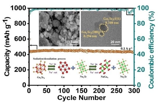
- 1st discharge
- Intercalation stageGa2Te3 + xNa+ + xe− → NaxGa2Te3 (2.5−1.37 V). (i)
- Conversion stageNaxGa2Te3 + (6−) Na+ + (6−x)e− → 3Na2Te + 2Ga (1.37−0.52 V). (ii)
- Alloy stage4Ga + Na+ + e− → NaGa4 (0.52−0.005 V). (iii)
- ❖
- 1st charge
- De-alloy stageNaGa4 → 4Ga + Na+ + e- (0.005−0.92 V). (iv)
- De-conversion stage3Na2Te + 2Ga → LixGa2Te3 + (6−x) Na+ + (6−x)e− (0.92−1.72 V). (v)
- De-intercalation stageNaxGa2Te3 → Ga2Te3 + xNa+ +xe− (1.72−2.5 V). (vi)
4. Conclusions
Supplementary Materials
Author Contributions
Funding
Institutional Review Board Statement
Informed Consent Statement
Data Availability Statement
Conflicts of Interest
References
- Dunn, B.; Kamath, H.; Tarascon, J.-M. Electrical Energy Storage for the Grid: A Battery of Choices. Science 2011, 334, 928–935. [Google Scholar] [CrossRef] [PubMed]
- Etacheri, V.; Marom, R.; Elazari, R.; Salitra, G.; Aurbach, D. Challenges in the development of advanced Li-ion batteries: A review. Energy Environ. Sci. 2011, 4, 3243–3262. [Google Scholar] [CrossRef]
- Sung, G.-K.; Nam, K.-H.; Choi, J.-H.; Park, C.-M. Germanium telluride: Layered high-performance anode for sodium-ion batteries. Electrochim. Acta 2020, 331, 135393. [Google Scholar] [CrossRef]
- Nguyen, T.P.; Kim, I.T. Ag Nanoparticle-Decorated MoS2 Nanosheets for Enhancing Electrochemical Performance in Lithium Storage. Nanomaterials 2021, 11, 626. [Google Scholar] [CrossRef]
- Nguyen, T.P.; Kim, I.T. Self-Assembled Few-Layered MoS2 on SnO2 Anode for Enhancing Lithium-Ion Storage. Nanomaterials 2020, 10, 2558. [Google Scholar] [CrossRef]
- Preman, A.N.; Lee, H.; Yoo, J.; Kim, I.T.; Saito, T.; Ahn, S.-k. Progress of 3D network binders in silicon anodes for lithium ion batteries. J. Mater. Chem. A 2020, 8, 25548–25570. [Google Scholar] [CrossRef]
- Nguyen, T.P.; Kim, I.T. W2C/WS2 Alloy Nanoflowers as Anode Materials for Lithium-Ion Storage. Nanomaterials 2020, 10, 1336. [Google Scholar] [CrossRef]
- Kim, W.S.; Vo, T.N.; Kim, I.T. GeTe-TiC-C Composite Anodes for Li-Ion Storage. Materials 2020, 13, 4222. [Google Scholar] [CrossRef]
- Vo, T.N.; Kim, D.S.; Mun, Y.S.; Lee, H.J.; Ahn, S.-k.; Kim, I.T. Fast charging sodium-ion batteries based on Te-P-C composites and insights to low-frequency limits of four common equivalent impedance circuits. Chem. Eng. J. 2020, 398, 125703. [Google Scholar] [CrossRef]
- Hoang Huy, V.P.; Kim, I.T.; Hur, J. The Effects of the Binder and Buffering Matrix on InSb-Based Anodes for High-Performance Rechargeable Li-Ion Batteries. Nanomaterials 2021, 11, 3420. [Google Scholar] [CrossRef]
- Nguyen, Q.; Phung, V.; Kidanu, W.; Ahn, Y.; Nguyen, T.; Kim, I.T. Carbon-free Cu/SbxOy/Sb nanocomposites with yolk-shell and hollow structures as high-performance anodes for lithium-ion storage. J. Alloys Compd. 2021, 878, 160447. [Google Scholar] [CrossRef]
- Nguyen, T.P.; Kim, I.T. In Situ Growth of W2C/WS2 with Carbon-Nanotube Networks for Lithium-Ion Storage. Nanomaterials 2022, 12, 1003. [Google Scholar] [CrossRef] [PubMed]
- Nguyen, T.P.; Kim, I.T. Boron Oxide Enhancing Stability of MoS2 Anode Materials for Lithium-Ion Batteries. Materials 2022, 15, 2034. [Google Scholar] [CrossRef] [PubMed]
- Phan Nguyen, T.; Thi Giang, T.; Tae Kim, I. Restructuring NiO to LiNiO2: Ultrastable and reversible anodes for lithium-ion batteries. Chem. Eng. J. 2022, 437, 135292. [Google Scholar] [CrossRef]
- Tarascon, J.-M. Is lithium the new gold? Nat. Chem. 2010, 2, 510. [Google Scholar] [CrossRef] [PubMed]
- Liu, Y.; He, D.; Han, R.; Wei, G.; Qiao, Y. Nanostructured potassium and sodium ion incorporated Prussian blue frameworks as cathode materials for sodium-ion batteries. Chem. Commun. 2017, 53, 5569–5572. [Google Scholar] [CrossRef]
- Liu, Y.; Qiao, Y.; Wei, G.; Li, S.; Lu, Z.; Wang, X.; Lou, X. Sodium storage mechanism of N, S co-doped nanoporous carbon: Experimental design and theoretical evaluation. Energy Storage Mater. 2018, 11, 274–281. [Google Scholar] [CrossRef]
- Qiao, Y.; Ma, M.; Liu, Y.; Li, S.; Lu, Z.; Yue, H.; Dong, H.; Cao, Z.; Yin, Y.; Yang, S. First-principles and experimental study of nitrogen/sulfur co-doped carbon nanosheets as anodes for rechargeable sodium ion batteries. J. Mater. Chem. A 2016, 4, 15565–15574. [Google Scholar] [CrossRef]
- Zhang, S.; Yao, F.; Yang, L.; Zhang, F.; Xu, S. Sulfur-doped mesoporous carbon from surfactant-intercalated layered double hydroxide precursor as high-performance anode nanomaterials for both Li-ion and Na-ion batteries. Carbon 2015, 93, 143–150. [Google Scholar] [CrossRef]
- Chevrier, V.L.; Ceder, G. Challenges for Na-ion Negative Electrodes. J. Electrochem. Soc. 2011, 158, A1011. [Google Scholar] [CrossRef]
- Qin, D.; Liu, Z.; Zhao, Y.; Xu, G.; Zhang, F.; Zhang, X. A sustainable route from corn stalks to N, P-dual doping carbon sheets toward high performance sodium-ion batteries anode. Carbon 2018, 130, 664–671. [Google Scholar] [CrossRef]
- Gan, Q.; He, H.; Zhao, K.; He, Z.; Liu, S.; Yang, S. Plasma-Induced Oxygen Vacancies in Urchin-Like Anatase Titania Coated by Carbon for Excellent Sodium-Ion Battery Anodes. ACS Appl. Mater. Interface. 2018, 10, 7031–7042. [Google Scholar] [CrossRef] [PubMed]
- Lu, P.; Sun, Y.; Xiang, H.; Liang, X.; Yu, Y. 3D Amorphous Carbon with Controlled Porous and Disordered Structures as a High-Rate Anode Material for Sodium-Ion Batteries. Adv. Energy Mater. 2018, 8, 1702434. [Google Scholar] [CrossRef]
- Chen, T.; Ma, Y.; Guo, Q.; Yang, M.; Xia, H. A facile sol–gel route to prepare functional graphene nanosheets anchored with homogeneous cobalt sulfide nanoparticles as superb sodium-ion anodes. J. Mater. Chem. A 2017, 5, 3179–3185. [Google Scholar] [CrossRef]
- Xiao, Y.; Lee, S.H.; Sun, Y.-K. The Application of Metal Sulfides in Sodium Ion Batteries. Adv. Energy Mater. 2017, 7, 1601329. [Google Scholar] [CrossRef]
- Peng, S.; Han, X.; Li, L.; Zhu, Z.; Cheng, F.; Srinivansan, M.; Adams, S.; Ramakrishna, S. Unique Cobalt Sulfide/Reduced Graphene Oxide Composite as an Anode for Sodium-Ion Batteries with Superior Rate Capability and Long Cycling Stability. Small 2016, 12, 1359–1368. [Google Scholar] [CrossRef]
- Ying, H.; Han, W.-Q. Metallic Sn-Based Anode Materials: Application in High-Performance Lithium-Ion and Sodium-Ion Batteries. Adv. Sci. 2017, 4, 1700298. [Google Scholar] [CrossRef]
- Liu, Z.; Yu, X.-Y.; Lou, X.W.; Paik, U. Sb@C coaxial nanotubes as a superior long-life and high-rate anode for sodium ion batteries. Energy Environ. Sci. 2016, 9, 2314–2318. [Google Scholar] [CrossRef]
- Liu, Y.; Zhang, A.; Shen, C.; Liu, Q.; Cao, X.; Ma, Y.; Chen, L.; Lau, C.; Chen, T.-C.; Wei, F.; et al. Red Phosphorus Nanodots on Reduced Graphene Oxide as a Flexible and Ultra-Fast Anode for Sodium-Ion Batteries. ACS Nano 2017, 11, 5530–5537. [Google Scholar] [CrossRef]
- Wang, X.; Hwang, J.-Y.; Myung, S.-T.; Hassoun, J.; Sun, Y.-K. Graphene Decorated by Indium Sulfide Nanoparticles as High-Performance Anode for Sodium-Ion Batteries. ACS Appl. Mater. Interface. 2017, 9, 23723–23730. [Google Scholar] [CrossRef]
- Ge, P.; Cao, X.; Hou, H.; Li, S.; Ji, X. Rodlike Sb2Se3 Wrapped with Carbon: The Exploring of Electrochemical Properties in Sodium-Ion Batteries. ACS Appl. Mater. Interface. 2017, 9, 34979–34989. [Google Scholar] [CrossRef] [PubMed]
- Liu, Y.; Kang, H.; Jiao, L.; Chen, C.; Cao, K.; Wang, Y.; Yuan, H. Exfoliated-SnS2 restacked on graphene as a high-capacity, high-rate, and long-cycle life anode for sodium ion batteries. Nanoscale 2015, 7, 1325–1332. [Google Scholar] [CrossRef] [PubMed]
- Deng, W.; Chen, J.; Yang, L.; Liang, X.; Yin, S.; Deng, X.; Zou, G.; Hou, H.; Ji, X. Solid Solution Metal Chalcogenides for Sodium-Ion Batteries: The Recent Advances as Anodes. Small 2021, 17, 2101058. [Google Scholar] [CrossRef]
- Zhang, J.; Yin, Y.-X.; Guo, Y.-G. High-Capacity Te Anode Confined in Microporous Carbon for Long-Life Na-Ion Batteries. ACS Appl. Mater. Interfaces 2015, 7, 27838–27844. [Google Scholar] [CrossRef] [PubMed]
- Wang, K.; Ye, W.; Yin, W.; Chai, W.; Rui, Y.; Tang, B. A novel carbon-coated Ga2S3 anode material derived from post-synthesis modified MOF for high performance lithium ion and sodium ion batteries. Electrochim. Acta 2019, 322, 134790. [Google Scholar] [CrossRef]
- Pang, S.; Hu, Z.; Fan, C.; Zhang, W.; Cai, Y.; Han, S.; Liu, J.; Liu, J. Insights into the sodium storage mechanism of Bi2Te3 nanosheets as superior anodes for sodium-ion batteries. Nanoscale 2022, 14, 1755–1766. [Google Scholar] [CrossRef]
- Yin, H.; Shen, W.; Qu, H.-Q.; Li, C.; Zhu, M.-Q. Boosted charge transfer and Na-ion diffusion in cooling-fins-like Sb2Te3–Te nano-heterostructure for long cycle life and high rate capability anode. Nano Energy 2020, 70, 104468. [Google Scholar] [CrossRef]
- Han, X.; Jiang, Q.; Zhang, M.; Qin, Z.; Geng, H.; Sun, C.; Gu, H. Pseudocapacitance-boosted ultrafast and stable Na-storage in NiTe2 coupled with N-doped carbon nanosheets for advanced sodium-ion half/full batteries. Dalton Trans. 2021, 50, 17241–17248. [Google Scholar] [CrossRef]
- Cho, J.S.; Lee, S.Y.; Lee, J.-K.; Kang, Y.C. Iron Telluride-Decorated Reduced Graphene Oxide Hybrid Microspheres as Anode Materials with Improved Na-Ion Storage Properties. ACS Appl. Mater. Interfaces 2016, 8, 21343–21349. [Google Scholar] [CrossRef]
- Nagulapati, V.M.; Lee, J.H.; Kim, H.S.; Oh, J.; Kim, I.T.; Hur, J.; Lee, S.G. Novel hybrid binder mixture tailored to enhance the electrochemical performance of SbTe bi-metallic anode for sodium ion batteries. J. Electroanal. Chem. 2020, 865, 114160. [Google Scholar] [CrossRef]
- Yang, M.; Zhang, W.; Su, D.; Wen, J.; Liu, L.; Wang, X. Flexible SnTe/carbon nanofiber membrane as a free-standing anode for high-performance lithium-ion and sodium-ion batteries. J. Colloid Interface Sci. 2022, 605, 231–240. [Google Scholar] [CrossRef] [PubMed]
- Panda, M.R.; Raj, K.A.; Ghosh, A.; Kumar, A.; Muthuraj, D.; Sau, S.; Yu, W.; Zhang, Y.; Sinha, A.K.; Weyland, M.; et al. Blocks of molybdenum ditelluride: A high rate anode for sodium-ion battery and full cell prototype study. Nano Energy 2019, 64, 103951. [Google Scholar] [CrossRef]
- Liang, M.; Ma, L.; Chen, B.; Liu, E.; Shi, C.; He, C.; Zhao, N. Two Birds with One Stone: A NaCl-Assisted Strategy toward MoTe2 Nanosheets Nanoconfined in 3D Porous Carbon Network for Sodium-Ion Battery Anode. Energy Storage Mater. 2022, 47, 591–601. [Google Scholar] [CrossRef]
- Zhang, W.; Wang, X.; Wong, K.W.; Zhang, W.; Chen, T.; Zhao, W.; Huang, S. Rational Design of Embedded CoTe2 Nanoparticles in Freestanding N-Doped Multichannel Carbon Fibers for Sodium-Ion Batteries with Ultralong Cycle Lifespan. ACS Appl. Mater. Interfaces 2021, 13, 34134–34144. [Google Scholar] [CrossRef] [PubMed]
- Seo, J.-U.; Seong, G.-K.; Park, C.-M. Te/C nanocomposites for Li-Te Secondary Batteries. Sci. Rep. 2015, 5, 7969. [Google Scholar] [CrossRef]
- He, J.; Chen, Y.; Lv, W.; Wen, K.; Wang, Z.; Zhang, W.; Li, Y.; Qin, W.; He, W. Three-Dimensional Hierarchical Reduced Graphene Oxide/Tellurium Nanowires: A High-Performance Freestanding Cathode for Li–Te Batteries. ACS Nano 2016, 10, 8837–8842. [Google Scholar] [CrossRef]
- Liu, Y.; Wang, J.; Xu, Y.; Zhu, Y.; Bigio, D.; Wang, C. Lithium–tellurium batteries based on tellurium/porous carbon composite. J. Mater. Chem. A 2014, 2, 12201–12207. [Google Scholar] [CrossRef]
- Cho, J.S.; Ju, H.S.; Lee, J.-K.; Kang, Y.C. Carbon/two-dimensional MoTe2 core/shell-structured microspheres as an anode material for Na-ion batteries. Nanoscale 2017, 9, 1942–1950. [Google Scholar] [CrossRef]
- Yang, W.; Zhang, X.; Tan, H.; Yang, D.; Feng, Y.; Rui, X.; Yu, Y. Gallium-based anodes for alkali metal ion batteries. J. Energy Chem. 2021, 55, 557–571. [Google Scholar] [CrossRef]
- Yarema, M.; Wörle, M.; Rossell, M.D.; Erni, R.; Caputo, R.; Protesescu, L.; Kravchyk, K.V.; Dirin, D.N.; Lienau, K.; von Rohr, F.; et al. Monodisperse Colloidal Gallium Nanoparticles: Synthesis, Low Temperature Crystallization, Surface Plasmon Resonance and Li-Ion Storage. J. Am. Chem. Soc. 2014, 136, 12422–12430. [Google Scholar] [CrossRef]
- Jeong, J.-H.; Jung, D.-W.; Oh, E.-S. Lithium storage characteristics of a new promising gallium selenide anodic material. J. Alloys Compd. 2014, 613, 42–45. [Google Scholar] [CrossRef]
- Zhang, C.; Park, S.-H.; Ronan, O.; Harvey, A.; Seral-Ascaso, A.; Lin, Z.; McEvoy, N.; Boland, C.S.; Berner, N.C.; Duesberg, G.S.; et al. Enabling Flexible Heterostructures for Li-Ion Battery Anodes Based on Nanotube and Liquid-Phase Exfoliated 2D Gallium Chalcogenide Nanosheet Colloidal Solutions. Small 2017, 13, 1701677. [Google Scholar] [CrossRef] [PubMed]
- Yang, W.; Chen, D.; Jiang, Y.; Feng, Y.; Rui, X.; Yu, Y. Synergetic enhancement of sodium storage in gallium-based heterostructures. Nano Energy 2021, 89, 106395. [Google Scholar] [CrossRef]
- Yang, M.; Sun, C.; Wang, T.; Chen, F.; Sun, M.; Zhang, L.; Shao, Y.; Wu, Y.; Hao, X. Graphene-Oxide-Assisted Synthesis of Ga2O3 Nanosheets/Reduced Graphene Oxide Nanocomposites Anodes for Advanced Alkali-Ion Batteries. ACS Appl. Energy Mater. 2018, 1, 4708–4715. [Google Scholar] [CrossRef]
- Wang, P.; Liu, M.; Mo, F.; Long, Z.; Fang, F.; Sun, D.; Zhou, Y.-n.; Song, Y. Exploring the sodium ion storage mechanism of gallium sulfide (Ga2S3): A combined experimental and theoretical approach. Nanoscale 2019, 11, 3208–3215. [Google Scholar] [CrossRef]
- Wu, Y.; Huang, L.; Huang, X.; Guo, X.; Liu, D.; Zheng, D.; Zhang, X.; Ren, R.; Qu, D.; Chen, J. A room-temperature liquid metal-based self-healing anode for lithium-ion batteries with an ultra-long cycle life. Energy Environ. Sci. 2017, 10, 1854–1861. [Google Scholar] [CrossRef]
- Voevodin, A.A.; Zabinski, J.S. Load-adaptive crystalline–amorphous nanocomposites. J. Mater. Sci. 1998, 33, 319–327. [Google Scholar] [CrossRef]
- Nguyen, Q.H.; Nguyen, Q.H.; So, S.; Hur, J. Efficient TiC-C hybrid conductive matrix for ZnTe anode in Lithium-ion storage. Appl. Surf. Sci. 2020, 534, 147679. [Google Scholar] [CrossRef]
- Hai Nguyen, Q.; So, S.; Hanh Nguyen, Q.; Kim, I.T.; Hur, J. Mechanochemical synthesis of InP nanoparticles embedded in hybrid conductive matrix for high-performance lithium-ion batteries. Chem. Eng. J. 2020, 399, 125826. [Google Scholar] [CrossRef]
- Nguyen, Q.H.; Nguyen, Q.H.; Hur, J. High-performance ZnTe-TiO2-C nanocomposite with half-cell and full-cell applications as promising anode material for Li-Ion batteries. Appl. Surf. Sci. 2020, 509, 144718. [Google Scholar] [CrossRef]
- Huy, V.P.H.; So, S.; Kim, I.T.; Hur, J. Self-healing gallium phosphide embedded in a hybrid matrix for high-performance Li-ion batteries. Energy Storage Mater. 2021, 34, 669–681. [Google Scholar] [CrossRef]
- Hieu, L.T.; So, S.; Kim, I.T.; Hur, J. Highly reversible lithiation/delithiation in indium antimonide with hybrid buffering matrix. Int. J. Energy Res. 2021, 45, 16145–16154. [Google Scholar] [CrossRef]
- Fan, T.-E.; Xie, H.-F. Sb2S3-rGO for high-performance sodium-ion battery anodes on Al and Cu foil current collector. J. Alloy. Compd. 2019, 775, 549–553. [Google Scholar] [CrossRef]
- Deng, M.; Li, S.; Hong, W.; Jiang, Y.; Xu, W.; Shuai, H.; Li, H.; Wang, W.; Hou, H.; Ji, X. Natural stibnite ore (Sb2S3) embedded in sulfur-doped carbon sheets: Enhanced electrochemical properties as anode for sodium ions storage. RSC Adv. 2019, 9, 15210–15216. [Google Scholar] [CrossRef]
- Lin, J.; Yao, L.; Zhang, C.; Ding, H.; Wu, Y.; Li, S.; Han, J.; Yue, G.; Peng, D. Construction of Sb2S3@SnS@C Tubular Heterostructures as High-Performance Anode Materials for Sodium-Ion Batteries. ACS Sustain. Chem. Eng. 2021, 9, 11280–11289. [Google Scholar] [CrossRef]
- Xie, J.; Liu, L.; Xia, J.; Zhang, Y.; Li, M.; Ouyang, Y.; Nie, S.; Wang, X. Template-Free Synthesis of Sb2S3 Hollow Microspheres as Anode Materials for Lithium-Ion and Sodium-Ion Batteries. Nano-Micro Lett. 2017, 10, 12. [Google Scholar] [CrossRef]
- Tang, X.; Huang, X.; Huang, Y.; Gou, Y.; Pastore, J.; Yang, Y.; Xiong, Y.; Qian, J.; Brock, J.D.; Lu, J.; et al. High-Performance Ga2O3 Anode for Lithium-Ion Batteries. ACS Appl. Mater. Interface. 2018, 10, 5519–5526. [Google Scholar] [CrossRef]
- Yuan, Y.; Yang, M.; Liu, L.; Xia, J.; Yan, H.; Liu, J.; Wen, J.; Zhang, Y.; Wang, X. The electrochemical storage mechanism of an In2S3/C nanofiber anode for high-performance Li-ion and Na-ion batteries. Nanoscale 2020, 12, 20337–20346. [Google Scholar] [CrossRef]
- Liu, B.; Cao, J.; Li, J.; Li, L.; Chen, D.; Zhang, S.; Cai, D.; Han, W. Highly conductive Co3Se4 embedded in N-doped 3D interconnected carbonaceous network for enhanced lithium and sodium storage. J. Colloid Interface. Sci. 2021, 586, 630–639. [Google Scholar] [CrossRef]
- Mahmood, A.; Ali, Z.; Tabassum, H.; Akram, A.; Aftab, W.; Ali, R.; Khan, M.W.; Loomba, S.; Alluqmani, A.; Adil Riaz, M.; et al. Carbon Fibers Embedded With Iron Selenide (Fe3Se4) as Anode for High-Performance Sodium and Potassium Ion Batteries. Front. Chem. 2020, 8, 408. [Google Scholar] [CrossRef]
- Nagulapati, V.M.; Kim, D.S.; Oh, J.; Lee, J.H.; Hur, J.; Kim, I.T.; Lee, S.G. Enhancing the Electrochemical Performance of SbTe Bimetallic Anodes for High-Performance Sodium-Ion Batteries: Roles of the Binder and Carbon Support Matrix. Nanomaterials 2019, 9, 1134. [Google Scholar] [CrossRef] [PubMed] [Green Version]


| Anode | Cycling Performance | Rate Capability | Synthesis Method | Ref. |
|---|---|---|---|---|
| Ga2S3 | 476 mAh·g−1 after 100 cycles at 0.4 A·g−1 | 283 mAh·g−1 at 2 A·g−1 | Vapor thermal annealing | [55] |
| Ga2S3–C | 385 mAh·g−1 after 200 cycles at 0.1 A·g−1 | 94 mAh·g−1 at 2.0 A·g−1 | Sulfuration process | [35] |
| Sb2Se3/C | 485.2 mAh·g−1 after 100 cycles at 0.2 A·g−1 | 237.9 mAh·g−1 at 2.0 A·g−1 | Hydrothermal process | [31] |
| Sb2S3–rGO | 537 mAh·g−1 after 70 cycles at 0.1 A·g−1 | 290 mAh·g−1 at 3.2 A·g−1 | Ultrasonication method | [63] |
| Sb2S3–C | 455.8 mAh·g−1 after 100 cycles at 0.1 A·g−1 | 263 mAh·g−1 at 1.0 A·g−1 | Modified natural stibnite ore | [64] |
| Sb2S3@SnS@C | 437 mAh·g−1 after 100 cycles at 1 A·g−1 | 448 mAh·g−1 at 5.0 A·g−1 | Hydrothermal method | [65] |
| Sb2S3 | 384 mAh·g−1 after 50 cycles at 0.2 A·g−1 | 239 mAh·g−1 at 5.0 A·g−1 | Hydrothermal method | [66] |
| In2S3/C | 372 mAh·g−1 after 200 cycles at 0.5 A·g−1 | 236 mAh·g−1 at 2.0 A·g−1 | Electrospinning process | [67,68] |
| Co3Se4@C | 449 mAh·g−1 after 20 cycles at 0.1 A·g−1 | 328 mAh·g−1 at 5.0 A·g−1 | Annealing process | [69] |
| Fe3Se4@C | 439 mAh·g−1 after 25 cycles at 0.05 A·g−1 | - | Electrospinning process | [70] |
| Bi2Te3 | 364 mAh·g−1 after 1200 cycles at 5 A·g−1 | 339 mAh·g−1 at 10 A·g−1 | Chemical reduction method | [36] |
| SbTe–C | 421 mAh·g−1 after 200 cycles at 0.1 A·g−1 | 413 mAh·g−1 at 1 A·g−1 | Ball milling | [71] |
| Ga2Te3–TiO2–C | 437 mAh·g−1 after 300 cycles at 0.1 A·g−1 | 318 mAh·g−1 at 10 A·g−1 | Ball milling | This work |
Publisher’s Note: MDPI stays neutral with regard to jurisdictional claims in published maps and institutional affiliations. |
© 2022 by the authors. Licensee MDPI, Basel, Switzerland. This article is an open access article distributed under the terms and conditions of the Creative Commons Attribution (CC BY) license (https://creativecommons.org/licenses/by/4.0/).
Share and Cite
Huy, V.P.H.; Kim, I.T.; Hur, J. Ga2Te3-Based Composite Anodes for High-Performance Sodium-Ion Batteries. Materials 2022, 15, 6231. https://doi.org/10.3390/ma15186231
Huy VPH, Kim IT, Hur J. Ga2Te3-Based Composite Anodes for High-Performance Sodium-Ion Batteries. Materials. 2022; 15(18):6231. https://doi.org/10.3390/ma15186231
Chicago/Turabian StyleHuy, Vo Pham Hoang, Il Tae Kim, and Jaehyun Hur. 2022. "Ga2Te3-Based Composite Anodes for High-Performance Sodium-Ion Batteries" Materials 15, no. 18: 6231. https://doi.org/10.3390/ma15186231