

Highly Loaded and Binder-Free Molybdenum Trioxide Cathode Material Prepared Using Multi-Arc Ion Plating for Aqueous Zinc Ion Batteries


Abstract
:
1. Introduction
2. Experiments
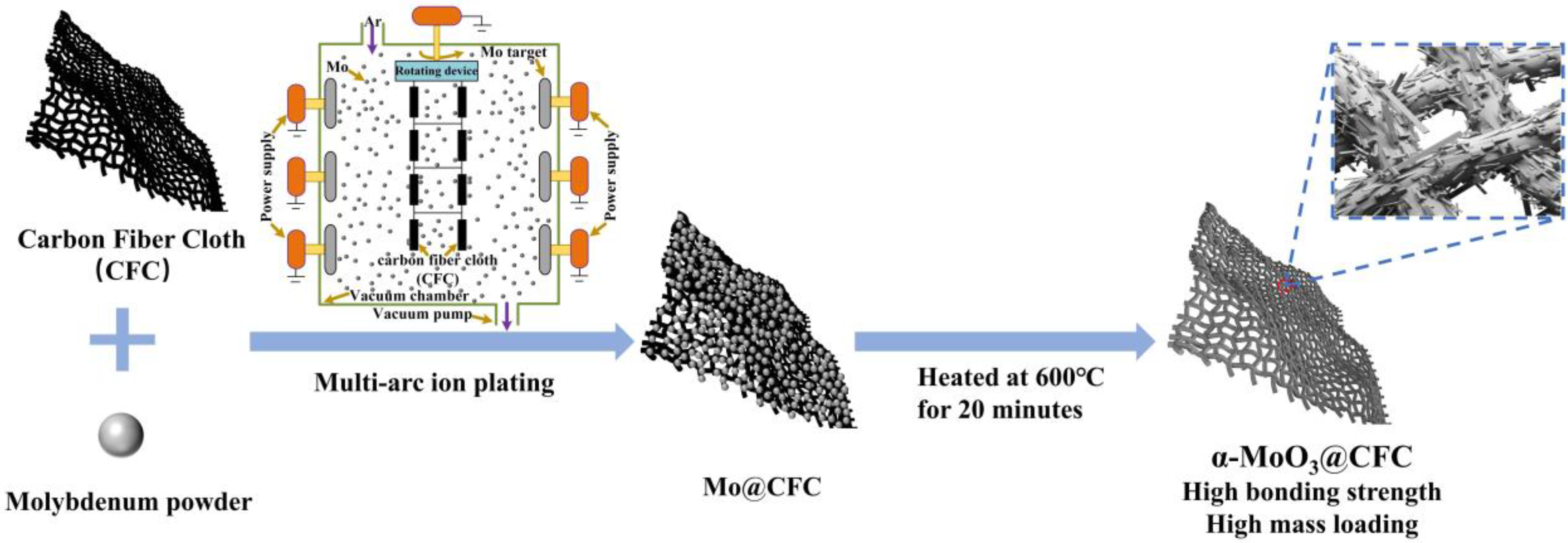
2.1. Material Synthesis
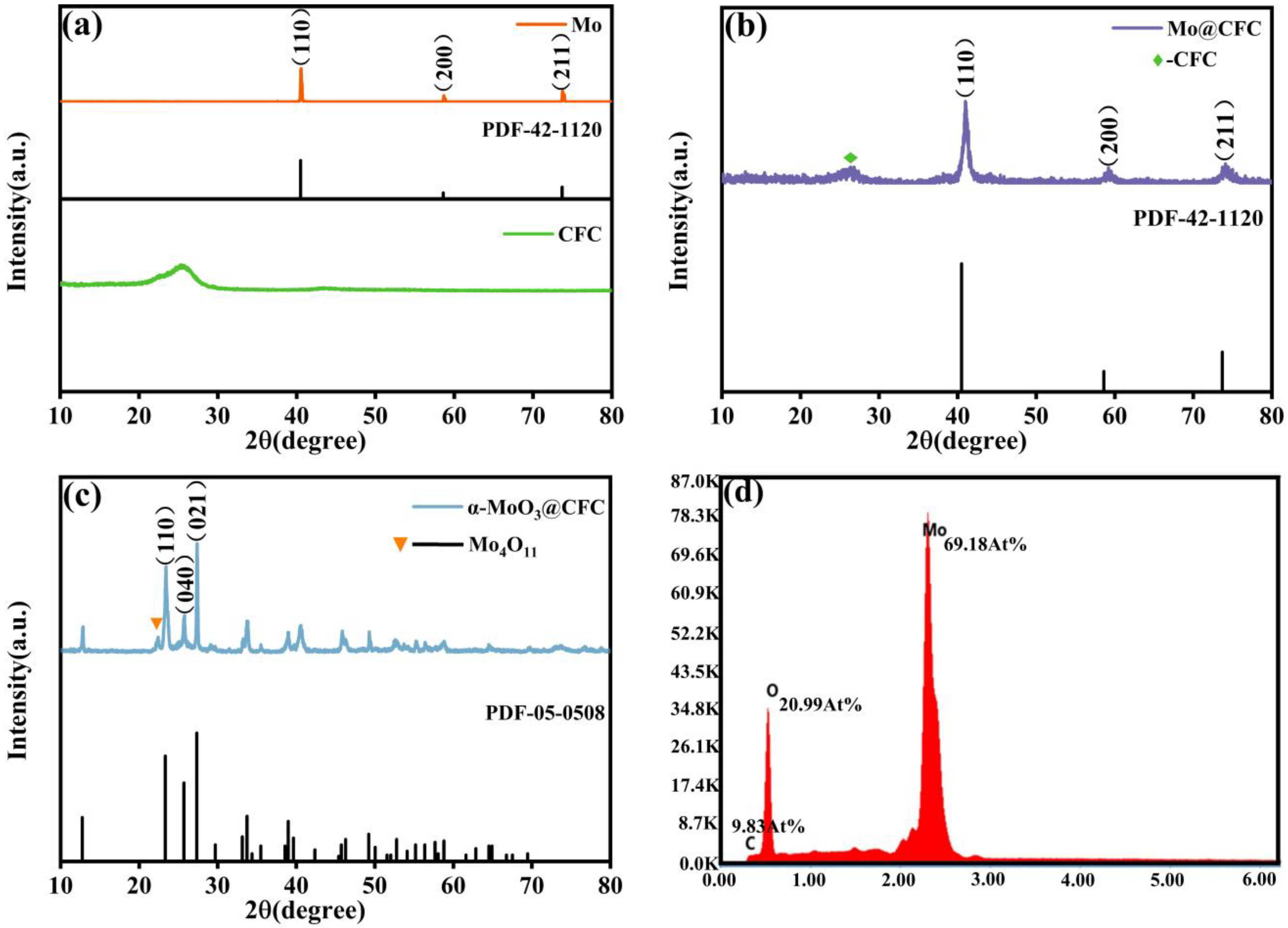
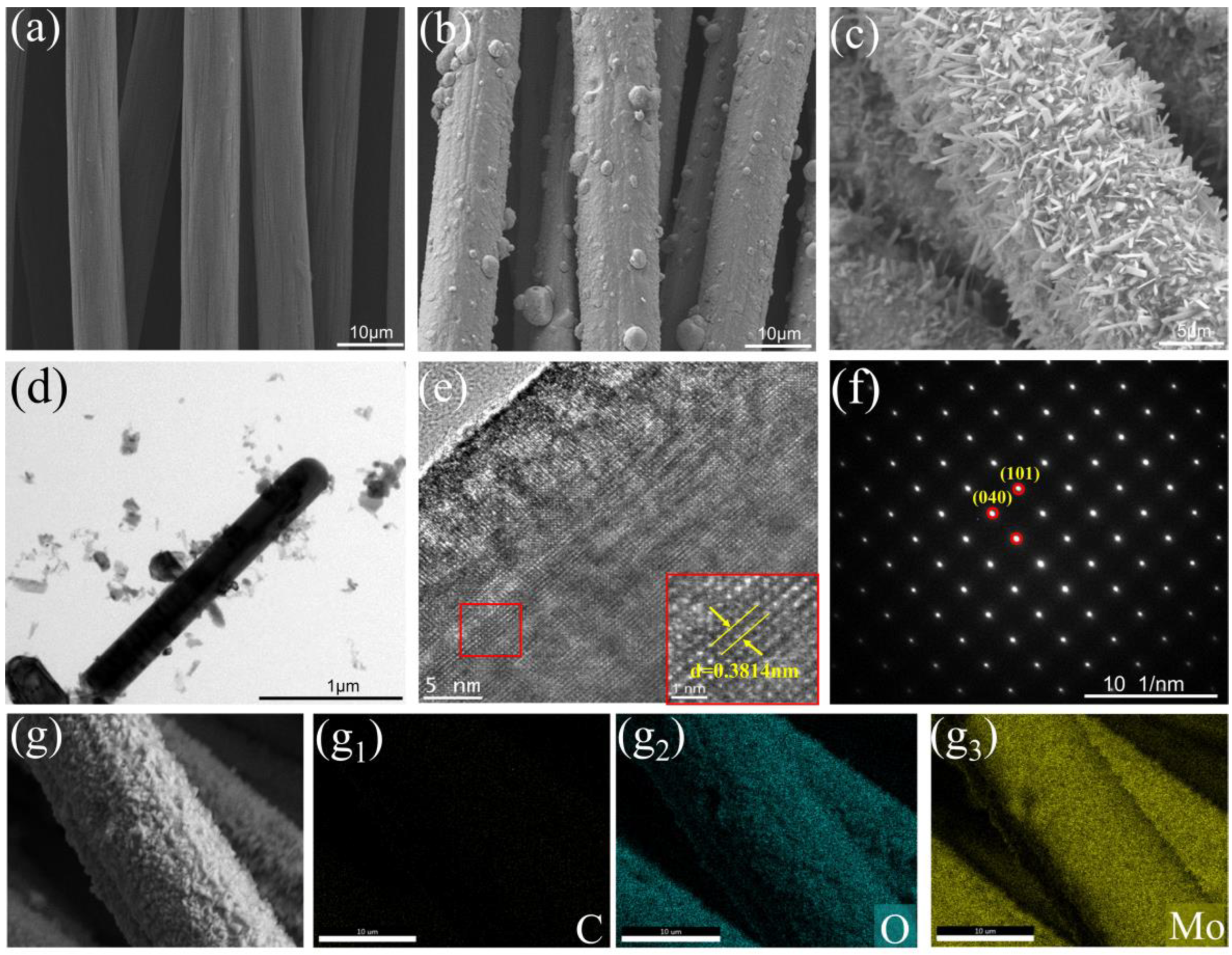
2.2. Material Characterization
2.3. Electrochemical Measurements
2.4. Results and Discussion
3. Conclusions
Supplementary Materials
Author Contributions
Funding
Institutional Review Board Statement
Informed Consent Statement
Data Availability Statement
Conflicts of Interest
References
- Tarascon, J.M.; Armand, M. Issues and challenges facing rechargeable lithium batteries. Nature 2001, 414, 359–367. [Google Scholar] [CrossRef] [PubMed]
- Lu, L.; Han, X.; Li, J.; Hua, J.; Ouyang, M. A review on the key issues for lithium-ion battery management in electric vehicles. J. Power Sources 2013, 226, 272–288. [Google Scholar] [CrossRef]
- Kim, T.; Song, W.; Son, D.-Y.; Ono, L.K.; Qi, Y. Lithium-ion batteries: Outlook on present, future, and hybridized technologies. J. Mater. Chem. A 2019, 7, 2942–2964. [Google Scholar] [CrossRef]
- Shi, Y.; Chen, Y.; Shi, L.; Wang, K.; Wang, B.; Li, L.; Ma, Y.; Li, Y.; Sun, Z.; Ali, W.; et al. An Overview and Future Perspectives of Rechargeable Zinc Batteries. Small 2020, 16, e2000730. [Google Scholar] [CrossRef]
- Chen, H.; Qin, H.; Chen, L.; Wu, J.; Yang, Z. V2O5@CNTs as cathode of aqueous zinc ion battery with high rate and high stability. J. Alloy. Compd. 2020, 842, 155912. [Google Scholar] [CrossRef]
- Huang, J.; Wang, Z.; Hou, M.; Dong, X.; Liu, Y.; Wang, Y.; Xia, Y. Polyaniline-intercalated manganese dioxide nanolayers as a high-performance cathode material for an aqueous zinc-ion battery. Nat. Commun. 2018, 9, 2906. [Google Scholar] [CrossRef]
- Wu, J.; Chi, X.W.; Liu, Y.Z.; Yang, J.H.; Liu, Y. Electrochemical characterization of hollow urchin-like MnO2 as high-performance cathode for aqueous zinc ion batteries. J. Electroanal. Chem. 2020, 871, 114242. [Google Scholar] [CrossRef]
- Xu, J.W.; Gao, Q.L.; Xia, Y.M.; Lin, X.S.; Liu, W.L.; Ren, M.M.; Kong, F.G.; Wang, S.J.; Lin, C. High-performance reversible aqueous zinc-ion battery based on iron-doped alpha-manganese dioxide coated by polypyrrole. J. Colloid Interface Sci. 2021, 598, 419–429. [Google Scholar] [CrossRef]
- Tang, B.; Zhou, J.; Fang, G.; Guo, S.; Guo, X.; Shan, L.; Tang, Y.; Liang, S. Structural Modification of V2O5 as High-Performance Aqueous Zinc-Ion Battery Cathode. J. Electrochem. Soc. 2019, 166, A480–A486. [Google Scholar] [CrossRef]
- Wei, T.; Li, Q.; Yang, G.; Wang, C. Highly reversible and long-life cycling aqueous zinc-ion battery based on ultrathin (NH4)2V10O25·8H2O nanobelts. J. Mater. Chem. A 2018, 6, 20402–20410. [Google Scholar] [CrossRef]
- Qin, M.L.; Liu, W.M.; Shan, L.T.; Fang, G.Z.; Cao, X.X.; Liang, S.Q.; Zhou, J. Construction of V2O5/NaV6O15 biphase composites as aqueous zinc-ion battery cathode. J. Electroanal. Chem. 2019, 847, 113246. [Google Scholar] [CrossRef]
- Mao, F.F.; Li, Y.W.; Zou, Z.G.; Huang, B.; Yang, J.W.; Yao, J.H. Zn2+ storage performance and structural change of orthorhombic V2O5 nanowires as the cathode material for rechargeable aqueous zinc-ion batteries. Electrochim. Acta 2021, 397, 139255. [Google Scholar] [CrossRef]
- Ni, G.; Xu, X.; Hao, Z.; Wang, W.; Li, C.; Yang, Y.; Zhou, C.; Qin, L.; Chen, W.; Yao, X.; et al. Tuning the Electrochemical Stability of Zinc Hexacyanoferrate through Manganese Substitution for Aqueous Zinc-Ion Batteries. ACS Appl. Energy Mater. 2020, 4, 602–610. [Google Scholar] [CrossRef]
- Lu, K.; Song, B.; Zhang, Y.; Ma, H.; Zhang, J. Encapsulation of zinc hexacyanoferrate nanocubes with manganese oxide nanosheets for high-performance rechargeable zinc ion batteries. J. Mater. Chem. A 2017, 5, 23628–23633. [Google Scholar] [CrossRef]
- Li, Z.; Liu, T.; Meng, R.; Gao, L.; Zou, Y.; Peng, P.; Shao, Y.; Liang, X. Insights into the Structure Stability of Prussian Blue for Aqueous Zinc Ion Batteries. Energy Environ. Mater. 2020, 4, 111–116. [Google Scholar] [CrossRef]
- Song, Y.; Duan, S.; Yang, D.; Dong, R.; Guo, D.; Sun, X.; Liu, X.-X. 3D Exfoliated Carbon Paper toward Highly Loaded Aqueous Energy Storage Applications. Energy Technol. 2019, 7, 1900892. [Google Scholar] [CrossRef]
- Jiao, T.; Yang, Q.; Wu, S.; Wang, Z.; Chen, D.; Shen, D.; Liu, B.; Cheng, J.; Li, H.; Ma, L.; et al. Binder-free hierarchical VS2 electrodes for high-performance aqueous Zn ion batteries towards commercial level mass loading. J. Mater. Chem. A 2019, 7, 16330–16338. [Google Scholar] [CrossRef]
- Li, Y.; Fu, J.; Zhong, C.; Wu, T.; Chen, Z.; Hu, W.; Amine, K.; Lu, J. Recent Advances in Flexible Zinc-Based Rechargeable Batteries. Adv. Energy Mater. 2018, 9, 1802605. [Google Scholar] [CrossRef]
- Yu, P.; Zeng, Y.; Zhang, H.; Yu, M.; Tong, Y.; Lu, X. Flexible Zn-Ion Batteries: Recent Progresses and Challenges. Small 2019, 15, e1804760. [Google Scholar] [CrossRef]
- Yao, M.; Yuan, Z.; Li, S.; He, T.; Wang, R.; Yuan, M.; Niu, Z. Scalable Assembly of Flexible Ultrathin All-in-One Zinc-Ion Batteries with Highly Stretchable, Editable, and Customizable Functions. Adv. Mater. 2021, 33, e2008140. [Google Scholar] [CrossRef]
- Chen, D.; Lu, M.; Wang, B.; Cheng, H.; Yang, H.; Cai, D.; Han, W.; Fan, H.J. High-mass loading V3O7·H2O nanoarray for Zn-ion battery: New synthesis and two-stage ion intercalation chemistry. Nano Energy 2021, 83, 106157. [Google Scholar] [CrossRef]
- Lei, J.; Yao, Y.; Wang, Z.; Lu, Y.-C. Towards high-areal-capacity aqueous zinc–manganese batteries: Promoting MnO2 dissolution by redox mediators. Energy Environ. Sci. 2021, 14, 4418–4426. [Google Scholar] [CrossRef]
- Ma, H.; Tian, X.; Wang, T.; Tang, K.; Liu, Z.; Hou, S.; Jin, H.; Cao, G. Tailoring Pore Structures of 3D Printed Cellular High-Loading Cathodes for Advanced Rechargeable Zinc-Ion Batteries. Small 2021, 17, e2100746. [Google Scholar] [CrossRef] [PubMed]
- Zhang, W.; Liang, S.; Fang, G.; Yang, Y.; Zhou, J. Ultra-High Mass-Loading Cathode for Aqueous Zinc-Ion Battery Based on Graphene-Wrapped Aluminum Vanadate Nanobelts. Nanomicro Lett. 2019, 11, 69. [Google Scholar] [CrossRef]
- He, X.; Zhang, H.; Zhao, X.; Zhang, P.; Chen, M.; Zheng, Z.; Han, Z.; Zhu, T.; Tong, Y.; Lu, X. Stabilized Molybdenum Trioxide Nanowires as Novel Ultrahigh-Capacity Cathode for Rechargeable Zinc Ion Battery. Adv. Sci. 2019, 6, 1900151. [Google Scholar] [CrossRef]
- Liu, Y.; Wang, J.; Zeng, Y.; Liu, J.; Liu, X.; Lu, X. Interfacial Engineering Coupled Valence Tuning of MoO3 Cathode for High-Capacity and High-Rate Fiber-Shaped Zinc-Ion Batteries. Small 2020, 16, e1907458. [Google Scholar] [CrossRef]
- Wang, Z.; Tian, C.; Tolstogouzov, A.; Liang, F.; Zou, C.; Li, S.; Gusev, S.I.; Yousaf, M.I.; Pelenovich, V.; Zuo, W.; et al. Microstructure and Rutherford Backscattering Spectrometry of Hard/Lubricant Mo-Ti-Al-N Multilayered Coatings Prepared by Multi-Arc Ion Plating at Low Substrate Rotation. Coatings 2020, 10, 101. [Google Scholar] [CrossRef]
- Wang, H.-D.; Xu, B.-S.; Liu, J.-J.; Zhuang, D.-M. Molybdenum disulfide coating deposited by hybrid treatment and its friction-reduction performance. Surf. Coat. Technol. 2007, 201, 6719–6722. [Google Scholar] [CrossRef]
- Xu, N.; Yan, C.; He, W.; Xu, L.; Jiang, Z.; Zheng, A.; Wu, H.; Chen, M.; Diao, G. Flexible electrode material of V2O5 carbon fiber cloth for enhanced zinc ion storage performance in flexible zinc-ion battery. J. Power Sources 2022, 533, 231358. [Google Scholar] [CrossRef]
- Qian, Y.; Meng, C.; He, J.; Dong, X. A lightweight 3D Zn@Cu nanosheets@activated carbon cloth as long-life anode with large capacity for flexible zinc ion batteries. J. Power Sources 2020, 480, 228871. [Google Scholar] [CrossRef]
- Tang, B.; Tian, N.; Jiang, J.; Li, Y.; Yang, J.; Zhu, Q. Investigation of zinc storage capacity of WS2 nanosheets for rechargeable aqueous Zn-ion batteries. J. Alloy. Compd. 2022, 894, 162391. [Google Scholar] [CrossRef]
- Wu, T.H.; Liang, W.Y. Reduced Intercalation Energy Barrier by Rich Structural Water in Spinel ZnMn2O4 for High-Rate Zinc-Ion Batteries. ACS Appl. Mater. Interfaces 2021, 13, 23822–23832. [Google Scholar] [CrossRef] [PubMed]
- Wang, L.; Yan, S.; Quilty, C.D.; Kuang, J.; Dunkin, M.R.; Ehrlich, S.N.; Ma, L.; Takeuchi, K.J.; Takeuchi, E.S.; Marschilok, A.C. Achieving Stable Molybdenum Oxide Cathodes for Aqueous Zinc-Ion Batteries in Water-in-Salt Electrolyte. Adv. Mater. Interfaces 2021, 8, 2002080. [Google Scholar] [CrossRef]


| Type of Material | Cycle Number, Cycling Capacity (mAh g−1) (Current Density (mA g−1)) | Mass Loading (mg cm−2) | Ref. |
|---|---|---|---|
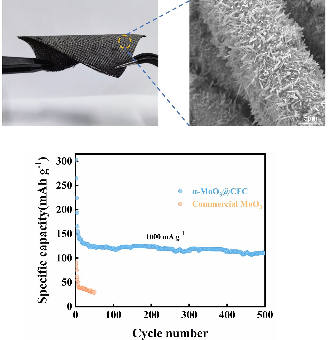
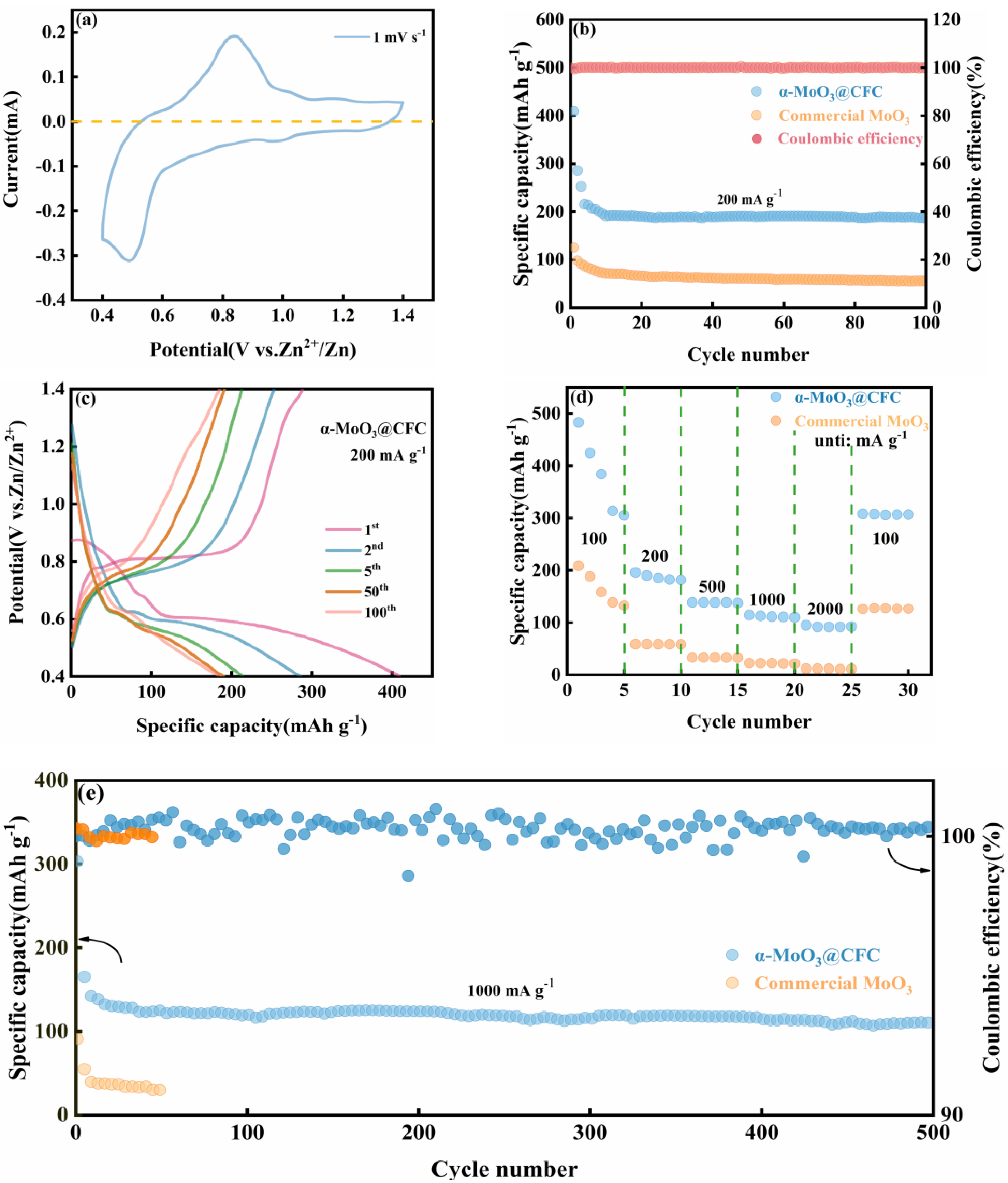
| α-MoO3@CFC | 100th, 200.8 (200) 500th, 109.8 (1000) | 12–15 | This Work |
| MoO3 nanowires | 400th, 171.14 (400) | 11.1 | [25] |
| MoO3 nanobelt | 100th, 254.77 (100) | 4.4–4.5 | [33] |
| V3O7⋅H2O nanoarray | 50th, 323 (100) 800th, 155 (2000) | 5 | [21] |
| H11Al2V6O23.2@graphene | 400th, 131.7 (2000) | 15.7 | [24] |
| 3D printed FeVO/rHGO | 650th, 126.4 (2000) | 12.4 | [23] |
| MnO2 composite electrode | 300th, 184 (200) | 9.5 | [16] |
Publisher’s Note: MDPI stays neutral with regard to jurisdictional claims in published maps and institutional affiliations. |
© 2022 by the authors. Licensee MDPI, Basel, Switzerland. This article is an open access article distributed under the terms and conditions of the Creative Commons Attribution (CC BY) license (https://creativecommons.org/licenses/by/4.0/).
Share and Cite
Liu, S.; Sun, Y.; Yang, J.; Zhang, Y.; Cai, Z. Highly Loaded and Binder-Free Molybdenum Trioxide Cathode Material Prepared Using Multi-Arc Ion Plating for Aqueous Zinc Ion Batteries. Materials 2022, 15, 5954. https://doi.org/10.3390/ma15175954
Liu S, Sun Y, Yang J, Zhang Y, Cai Z. Highly Loaded and Binder-Free Molybdenum Trioxide Cathode Material Prepared Using Multi-Arc Ion Plating for Aqueous Zinc Ion Batteries. Materials. 2022; 15(17):5954. https://doi.org/10.3390/ma15175954
Chicago/Turabian StyleLiu, Sainan, Yangyang Sun, Jing Yang, Yi Zhang, and Zhenyang Cai. 2022. "Highly Loaded and Binder-Free Molybdenum Trioxide Cathode Material Prepared Using Multi-Arc Ion Plating for Aqueous Zinc Ion Batteries" Materials 15, no. 17: 5954. https://doi.org/10.3390/ma15175954