
Experimental Study on Metal Parts under Variable 3D Printing and Sintering Orientations Using Bronze/PLA Hybrid Filament Coupled with Fused Filament Fabrication

Abstract
:1. Introduction
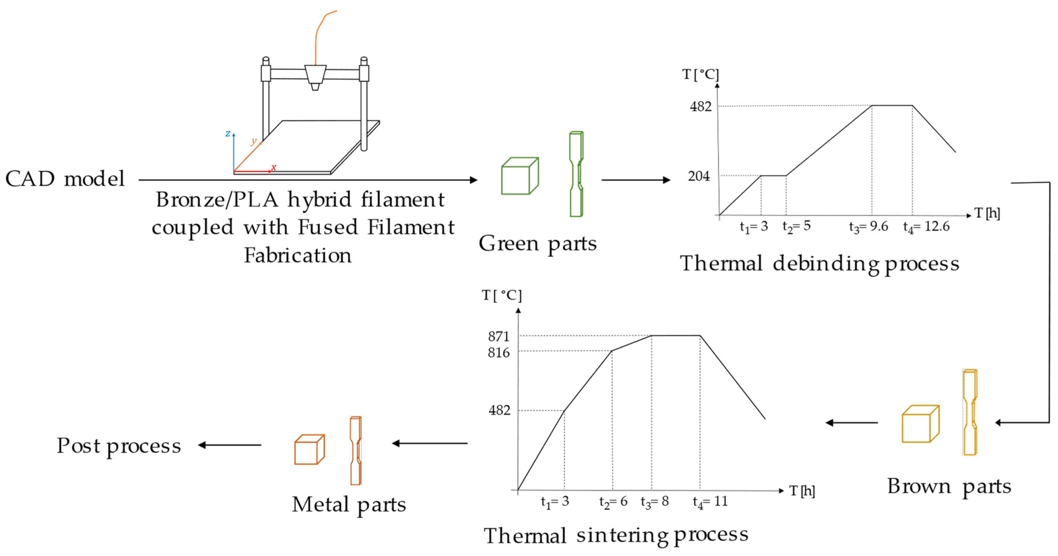
2. Materials and Methods
2.1. Materials
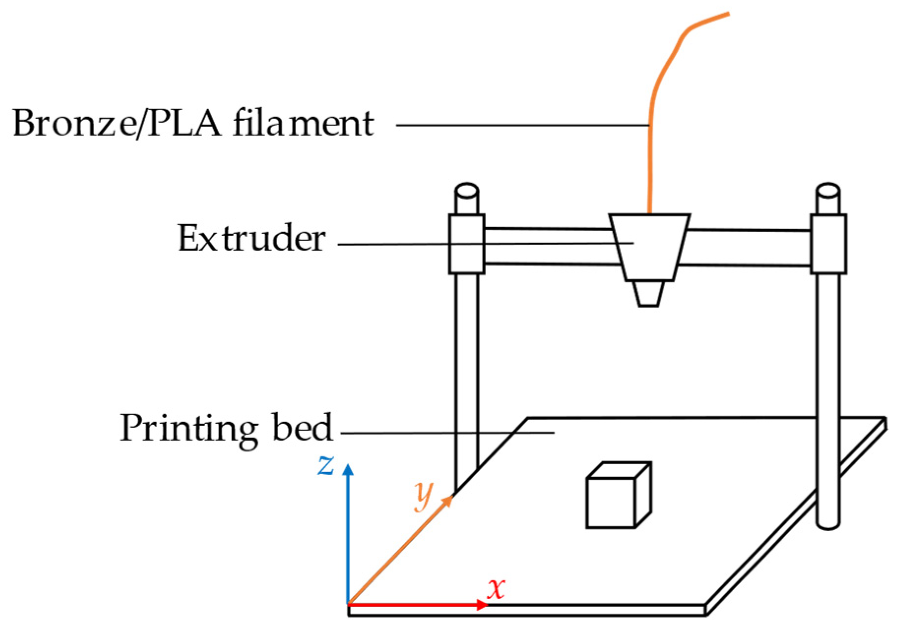
2.2. 3D Printing
2.3. Thermal Debinding and Sintering
2.4. Printing and Sintering Direction
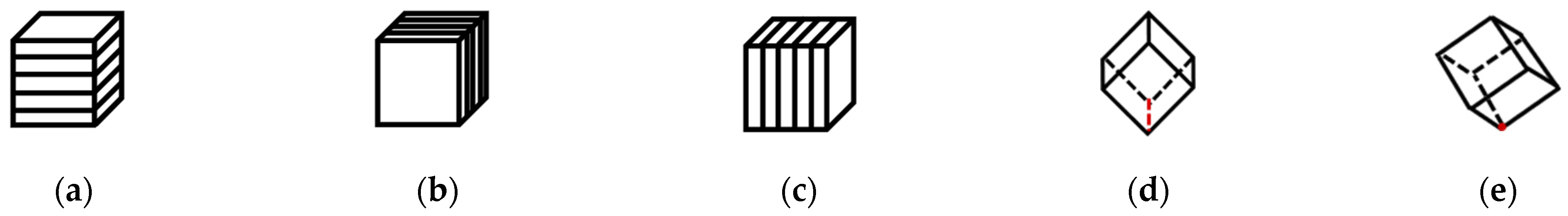
2.4.1. Printing and Sintering Direction for Cubes
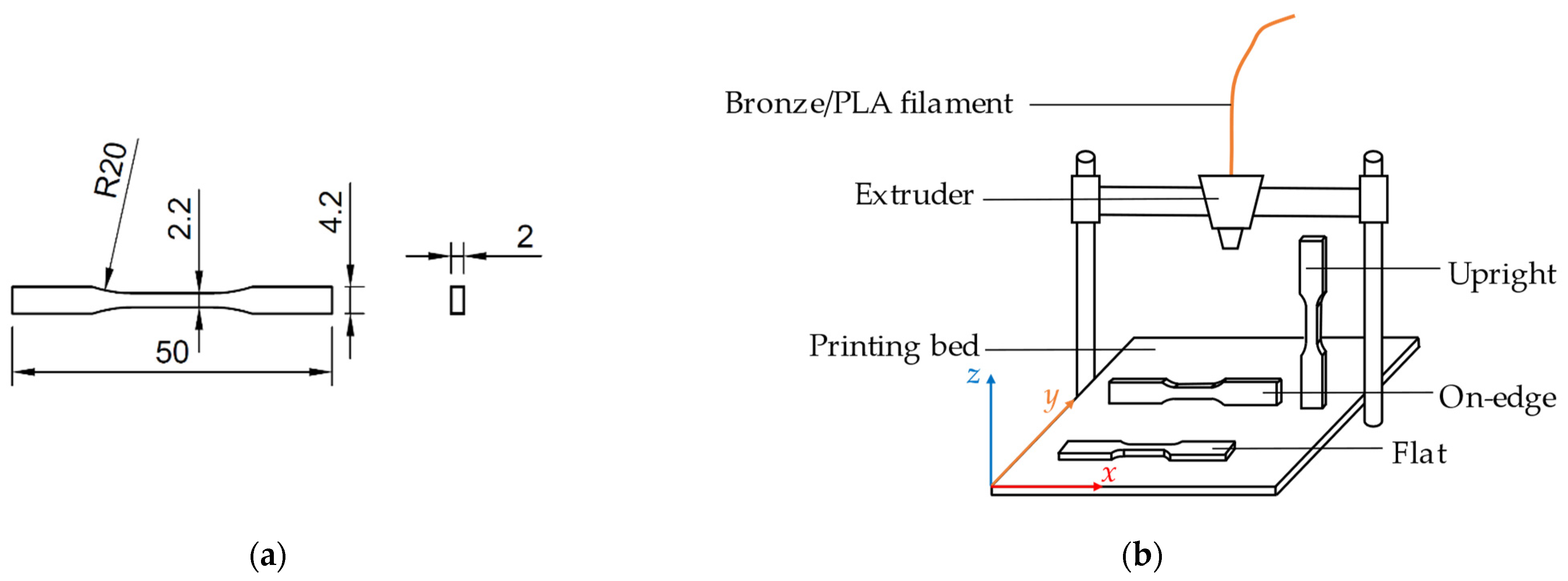
2.4.2. Printing and Sintering Directions for Tensile Specimens
2.5. Shrinkage and Density Analysis
2.6. Microstructural Characterization
2.7. Mechanical Characterization
3. Results and Discussion
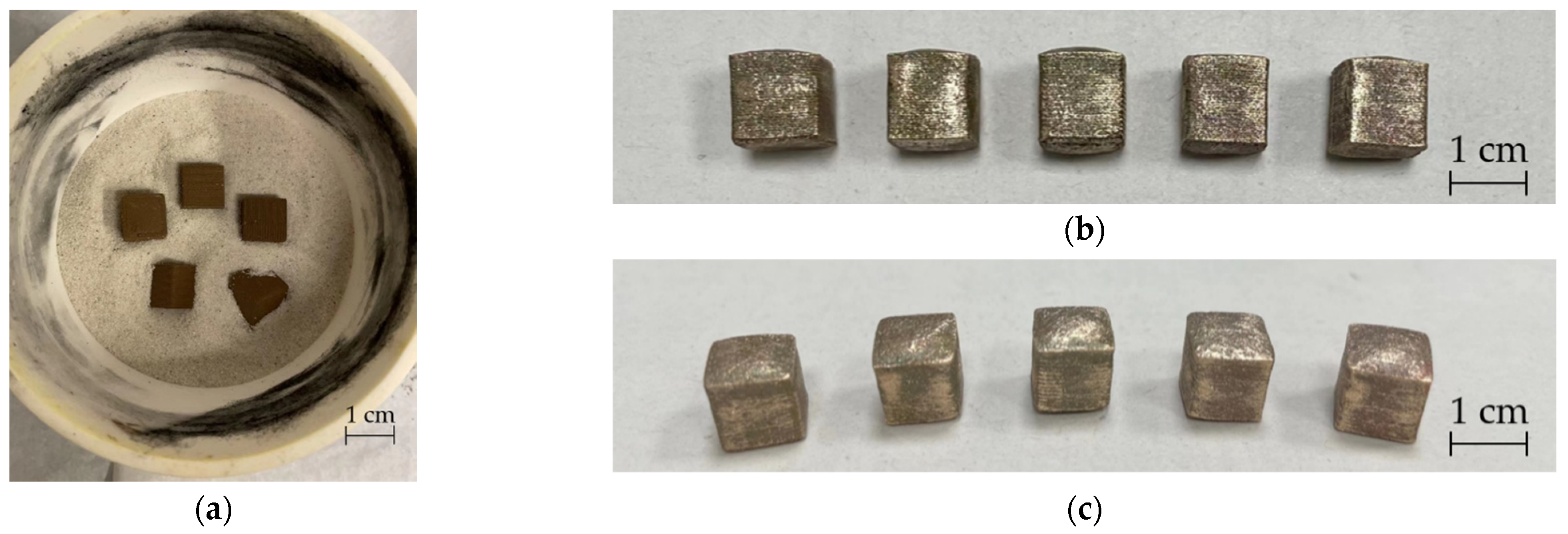
3.1. Shrinkage and Density Analysis through Sintered Cubes
3.2. Tensile Stress and Porosity Analysis through Tensile Specimens
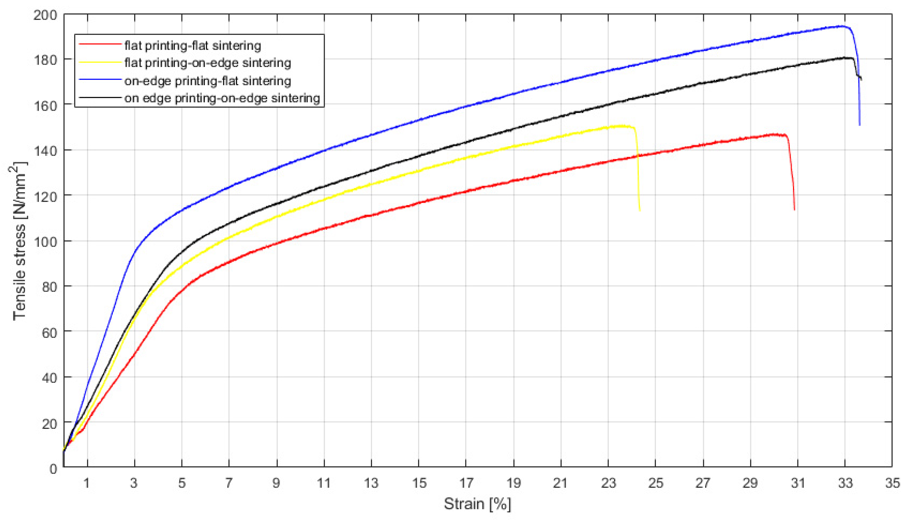
3.2.1. Tensile Stress Analysis
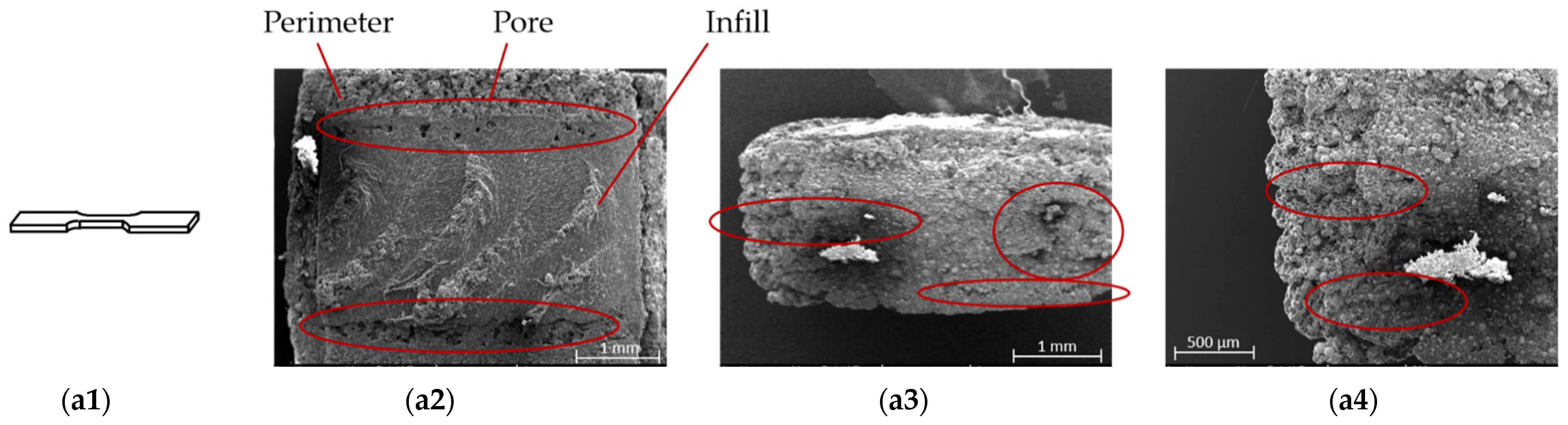
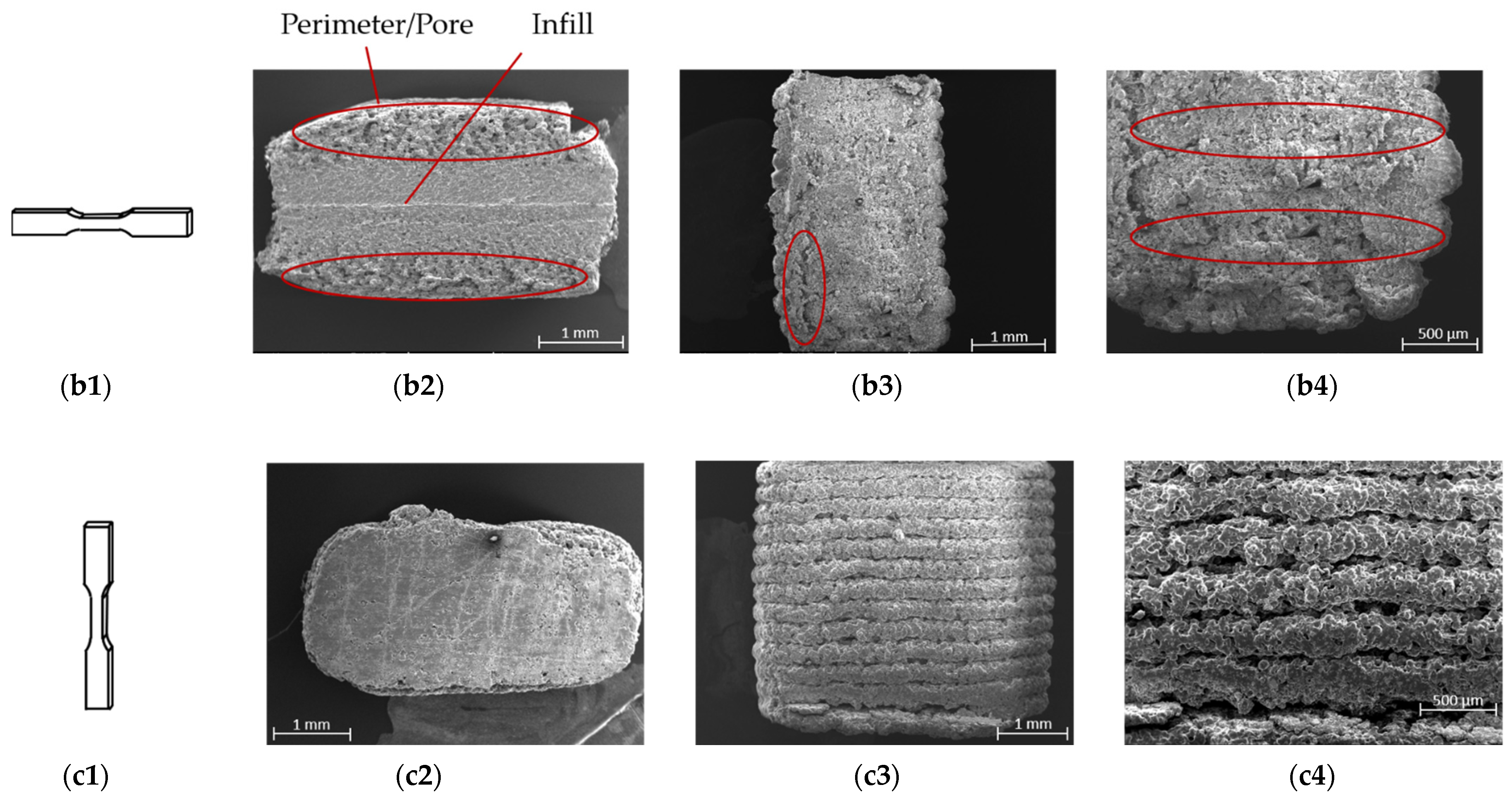
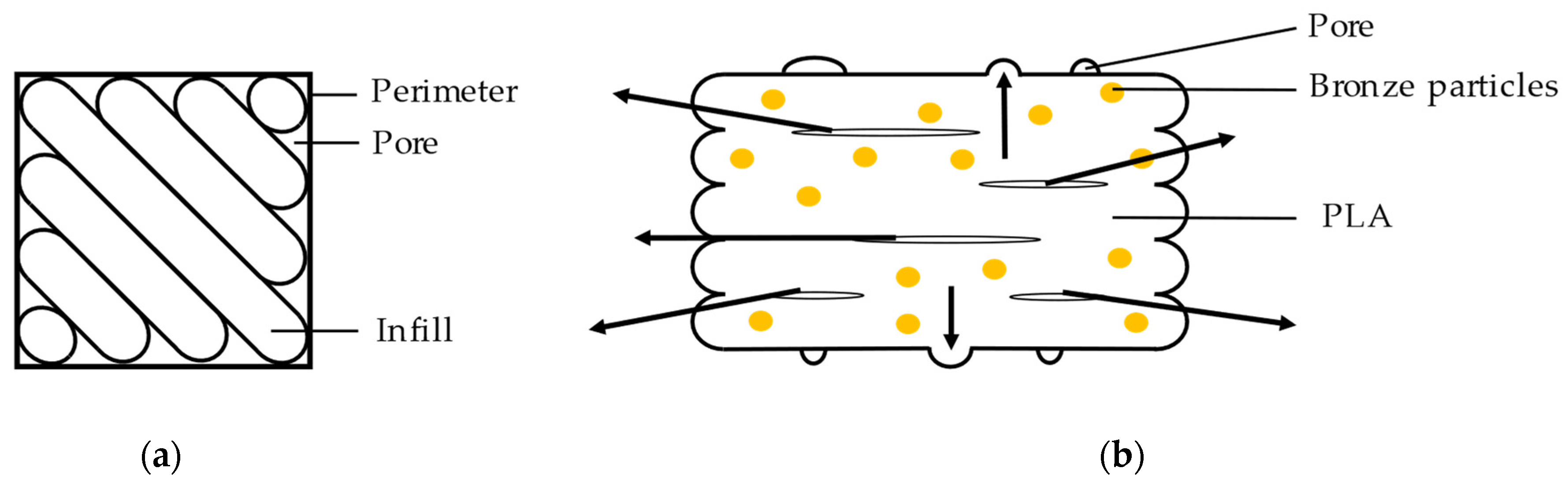
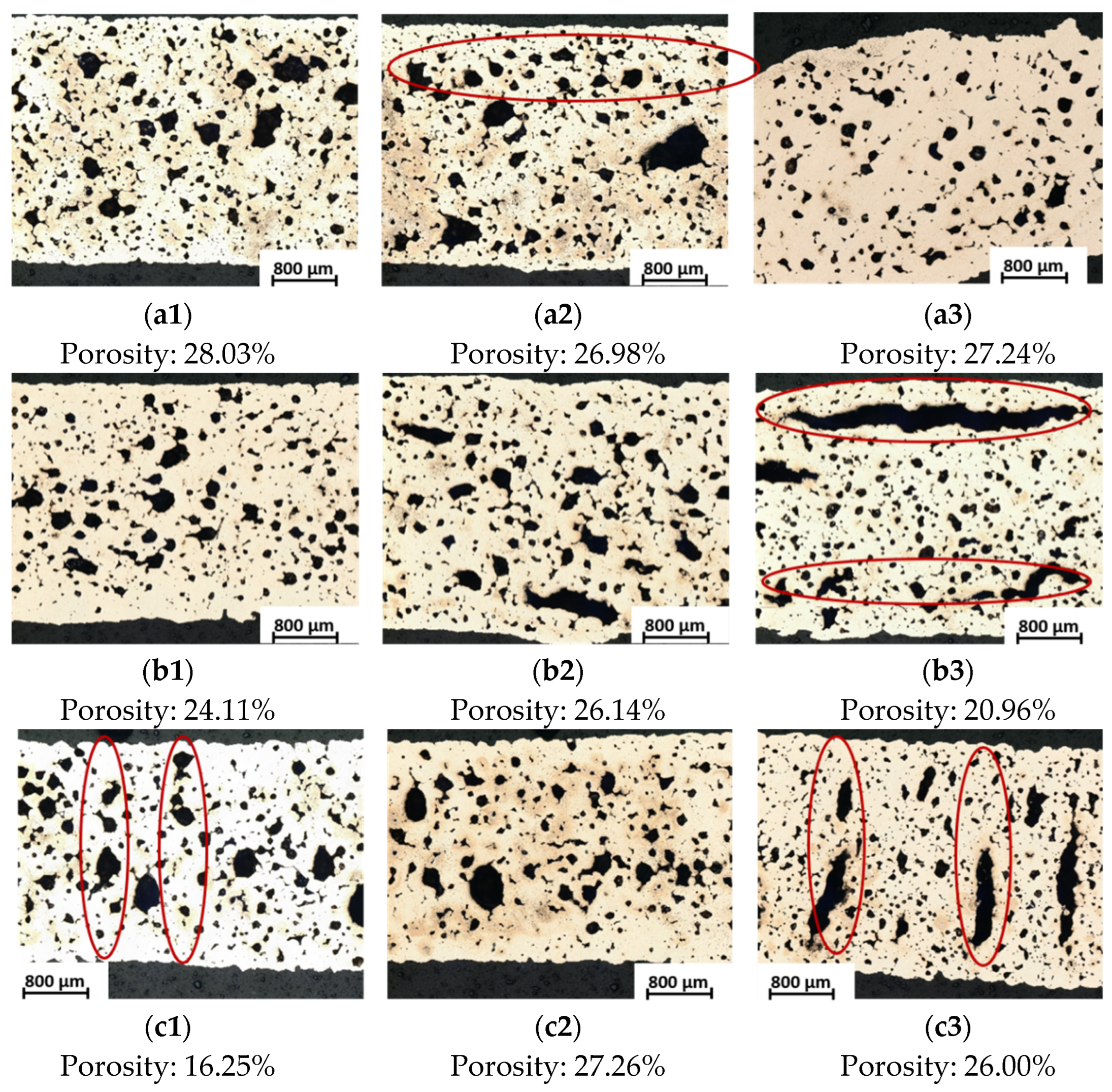
3.2.2. Microstructural and Porosity Analysis
4. Conclusions
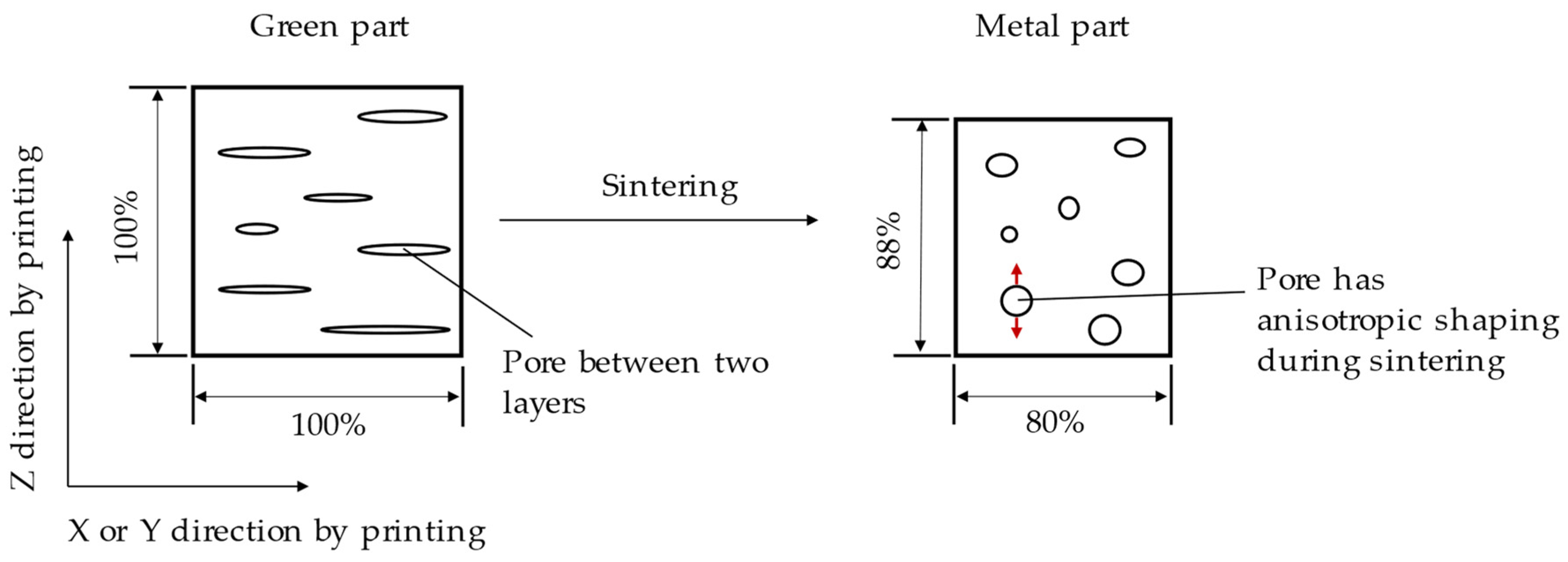
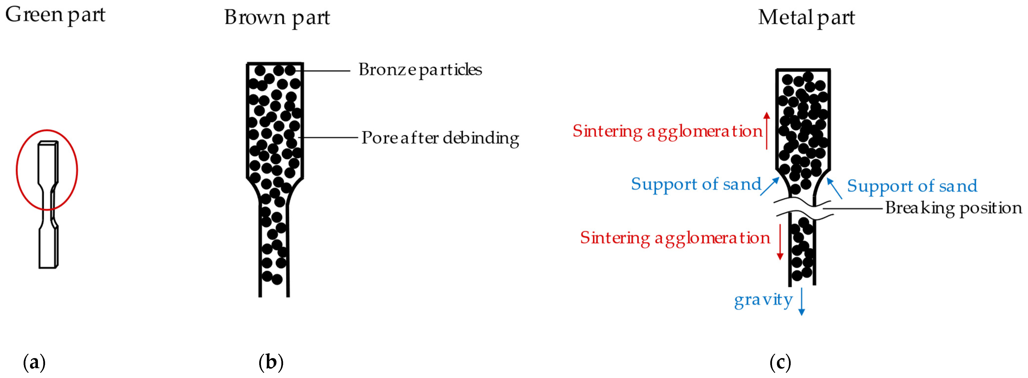
- Sintering orientations had only minor effects on shrinkage, density, and porosity. The results from different sintering directions were similar. Shrinkage in the layer direction was lower than in the x and y directions. The density of the parts was increased by about 6.6 g/cm3 after sintering. The porosity was independent of the sintering direction. Parts produced in the “upright” sintering direction resulted in weakness leading to fracturing.
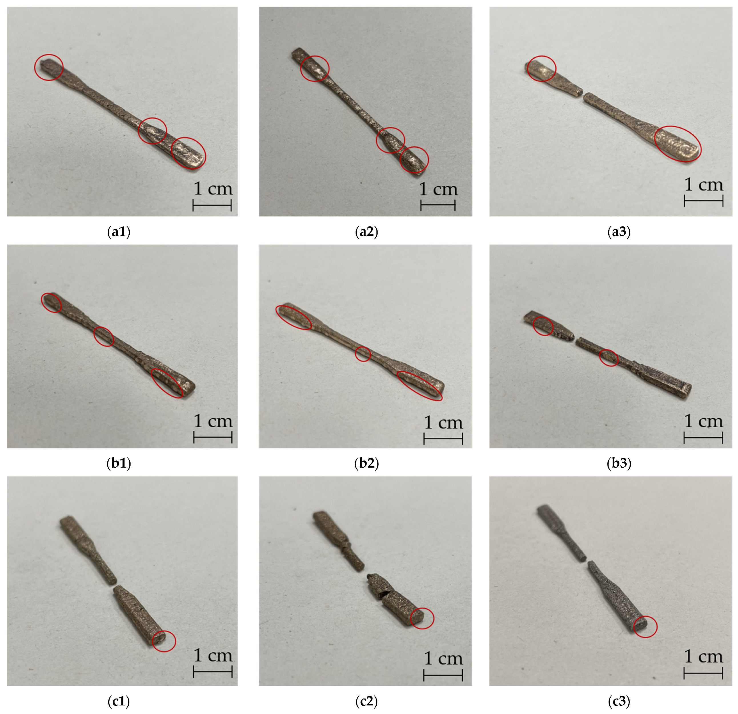
- The printing orientations played an important role in tensile stress and porosity. “Upright” printed specimens were weak. Conversely, “on-edge” printed specimens had the best tensile stress at about 190 MPa. In addition, porosity occurred on the surfaces of the parts that were parallel to the printing bed. The pore volume was dependent on the area of the horizontally printed surfaces.
- The best printing-sintering combination was “on-edge-flat”. The tensile stress and surface porosity supported these conclusions.
Author Contributions
Funding
Institutional Review Board Statement
Informed Consent Statement
Data Availability Statement
Acknowledgments
Conflicts of Interest
References
- Esper, F.J. Pulvermetallurgie: Das Flexible und fortschrittliche Verfahren für Wirtschaftliche und Zuverlässige Bauteile; Expert Verlag: Renningen-Malmsheim, Germany, 1996; ISBN 3-8169-1321-0. [Google Scholar]
- Ruthardt, R. Fertigungsoptimierung; DGM Informationsgesellschaft mbH: Frankfurt, Germany, 1996; ISBN 3-88355-225-9. [Google Scholar]
- Amin, A.M.; Ibrahim, M.H.I.; Asmawi, R.; Mustaffa, N.; Hashim, M.Y. Thermal Debinding and Sintering of water atomised SS316L Metal Injection Moulding Process. IOP Conf. Ser. Mater. Sci. Eng. 2017, 226, 12155. [Google Scholar] [CrossRef]
- Manam, N.S.; Harun, W.S.W.; Ibrahim, M.H.I.; Khalil, N.Z.; Samykano, M. Sintering temperature effects on the properties of stainless steel 316L compact fabricated by metal injection moulding. IJMTM 2019, 33, 37. [Google Scholar] [CrossRef]
- Supriadi, S.; Suharno, B.; Hidayatullah, R.; Maulana, G.; Baek, E.R. Thermal Debinding Process of SS 17-4 PH in Metal Injection Molding Process with Variation of Heating Rates, Temperatures, and Holding Times. SSP 2017, 266, 238–244. [Google Scholar] [CrossRef]
- Xu, Z.; Hodgson, M.; Chang, K.; Chen, G.; Yuan, X.; Cao, P. Effect of Sintering Time on the Densification, Microstructure, Weight Loss and Tensile Properties of a Powder Metallurgical Fe-Mn-Si Alloy. Metals 2017, 7, 81. [Google Scholar] [CrossRef] [Green Version]
- Tafti, A.A.; Demers, V.; Majdi, S.M.; Vachon, G.; Brailovski, V. Effect of Thermal Debinding Conditions on the Sintered Density of Low-Pressure Powder Injection Molded Iron Parts. Metals 2021, 11, 264. [Google Scholar] [CrossRef]
- Agne, A.; Barrière, T. Modelling and numerical simulation of Supercritical CO2 debinding of Inconel 718 components elaborated by Metal Injection Molding. Appl. Sci. 2017, 7, 1024. [Google Scholar] [CrossRef] [Green Version]
- Boschetto, A.; Bottini, L.; Veniali, F. Finishing of Fused Deposition Modeling parts by CNC machining. Robot. Comput. Integr. Manuf. 2016, 41, 92–101. [Google Scholar] [CrossRef]
- Gloeckle, C.; Konkol, T.; Jacobs, O.; Limberg, W.; Ebel, T.; Handge, U.A. Processing of Highly Filled Polymer-Metal Feedstocks for Fused Filament Fabrication and the Production of Metallic Implants. Materials 2020, 13, 4413. [Google Scholar] [CrossRef]
- Gonzalez-Gutierrez, J.; Cano, S.; Schuschnigg, S.; Kukla, C.; Sapkota, J.; Holzer, C. Additive Manufacturing of Metallic and Ceramic Components by the Material Extrusion of Highly-Filled Polymers: A Review and Future Perspectives. Materials 2018, 11, 840. [Google Scholar] [CrossRef] [Green Version]
- Godec, D.; Cano, S.; Holzer, C.; Gonzalez-Gutierrez, J. Optimization of the 3D Printing Parameters for Tensile Properties of Specimens Produced by Fused Filament Fabrication of 17-4PH Stainless Steel. Materials 2020, 13, 774. [Google Scholar] [CrossRef] [Green Version]
- Fafenrot, S.; Grimmelsmann, N.; Wortmann, M.; Ehrmann, A. Three-Dimensional (3D) Printing of Polymer-Metal Hybrid Materials by Fused Deposition Modeling. Materials 2017, 10, 1199. [Google Scholar] [CrossRef] [Green Version]
- Gong, H.; Crater, C.; Ordonez, A.; Ward, C.; Waller, M.; Ginn, C. Material Properties and Shrinkage of 3D Printing Parts using Ultrafuse Stainless Steel 316LX Filament. In Proceedings of the International Conference on Mechanical, Materials and Manufacturing (ICMMM 2018), Georgia Southern University, Statesboro, GA, USA. MATEC Web Conf. 2018, 249, 01001. [Google Scholar] [CrossRef]
- Caminero, M.Á.; Romero, A.; Chacón, J.M.; Núñez, P.J.; García-Plaza, E.; Rodríguez, G.P. Additive manufacturing of 316L stainless-steel structures using fused filament fabrication technology: Mechanical and geometric properties. RPJ 2021, 27, 583–591. [Google Scholar] [CrossRef]
- Kurose, T.; Abe, Y.; Santos, M.V.A.; Kanaya, Y.; Ishigami, A.; Tanaka, S.; Ito, H. Influence of the Layer Directions on the Properties of 316L Stainless Steel Parts Fabricated through Fused Deposition of Metals. Materials 2020, 13, 2493. [Google Scholar] [CrossRef] [PubMed]
- Burkhardt, C.; Freigassner, P.; Weber, O.; Imgrund, P.; Hampel, S. Fused Filament Fabrication (FFF) of 316L Green Parts for the MIM process. In Proceedings of the World PM2016—AM—Deposition Technologies, Hamburg, Germany, 9–13 October 2016. [Google Scholar]
- Thompson, Y.; Gonzalez-Gutierrez, J.; Kukla, C.; Felfer, P. Fused filament fabrication, debinding and sintering as a low cost additive manufacturing method of 316L stainless steel. Addit. Manuf. 2019, 30, 100861. [Google Scholar] [CrossRef]
- Liu, B.; Wang, Y.; Lin, Z.; Zhang, T. Creating metal parts by Fused Deposition Modeling and Sintering. Mater. Lett. 2020, 263, 127252. [Google Scholar] [CrossRef]
- Hamidi, M.F.F.A.; Harun, W.S.W.; Khalil, N.Z.; Ghani, S.A.C.; Azir, M.Z. Study of solvent debinding parameters for metal injection moulded 316L stainless steel. IOP Conf. Ser. Mater. Sci. Eng. 2017, 257, 12035. [Google Scholar] [CrossRef]
- Hasib, A.G.; Niauzorau, S.; Xu, W.; Niverty, S.; Kublik, N.; Williams, J.; Chawla, N.; Song, K.; Azeredo, B. Rheology scaling of spherical metal powders dispersed in thermoplastics and its correlation to the extrudability of filaments for 3D printing. Addit. Manuf. 2021, 41, 101967. [Google Scholar] [CrossRef]
- Hwang, K.S.; Tsou, T.H. Thermal debinding of powder injection molded parts: Observations and mechanisms. MTA 1992, 23, 2775–2782. [Google Scholar] [CrossRef]
- Jiang, D.; Ning, F. Fused Filament Fabrication of Biodegradable PLA/316L Composite Scaffolds: Effects of Metal Particle Content. Procedia Manuf. 2020, 48, 755–762. [Google Scholar] [CrossRef]
- DIN e.V. Kunststoffe—Bestimmung der Zugeigenschaften—Teil 2: Prüfbedingungen für Form- und Extrusionsmassen (ISO 527-2:2012); Deutsche Fassung EN ISO 527-2:2012; Beuth-Verlag: Berlin, 2012. Available online: https://www.beuth.de/de/norm/din-en-iso-527-2/148232494 (accessed on 10 July 2022).
- DIN e.V. Metallic Materials—Tensile Testing: Part 1: Method of Test at Room Temperature (ISO 6892-1:2019); German Version EN ISO 6892-1:2019; Beuth-Verlag: Berlin, 2020 (ICS 77.040.10). Available online: https://www.beuth.de/de/norm/din-en-iso-6892-1/317931281 (accessed on 10 July 2022).
- Randall, M. Powder Metallurgy of Iron and Steel; A Wiley-Interscience Publication: New York, NY, USA, 1995; ISBN 0-471-15739-2. [Google Scholar]
- Alloys. Available online: https://www.alspi.com/alloys.pdf (accessed on 10 July 2022).
- Metall—Physikalischen Eigenschaften. Available online: https://www.tabelle.info/metall.htm (accessed on 2 June 2021).
- Innorat. Metalle Physikalische Eigenschaften: Metallische Werkstoffe Physikalische Eigenschaften. Available online: https://innorat.ch/Metalle%20physikalische%20Eigenschaften_u2_90.html (accessed on 10 July 2022).
- Giri, J.; Chiwande, A.; Gupta, Y.; Mahatme, C.; Giri, P. Effect of process parameters on mechanical properties of 3d printed samples using FDM process. Mater. Today Proc. 2021, 47, 5856–5861. [Google Scholar] [CrossRef]
- Chacón, J.M.; Caminero, M.A.; García-Plaza, E.; Núñez, P.J. Additive manufacturing of PLA structures using fused deposition modelling: Effect of process parameters on mechanical properties and their optimal selection. Mater. Des. 2017, 124, 143–157. [Google Scholar] [CrossRef]
- Khalid, M.; Peng, Q. Investigation of Printing Parameters of Additive Manufacturing Process for Sustainability Using Design of Experiments. J. Mech. Des. 2021, 143, 032001. [Google Scholar] [CrossRef]
- Randall, M. Sintering Theory and Practice; A Wiley-Interscience Publication: New York, NY, USA, 1996; ISBN 0-471-05786-X. [Google Scholar]
- Schatt, W. Sintervorgänge: Grundlagen; VDI-Verlag GmbH: Düsseldorf, Germany, 1992; ISBN 3-18-401218-2. [Google Scholar]
- Wang, Q.; Ji, C.; Sun, L.; Sun, J.; Liu, J. Cellulose Nanofibrils Filled Poly(Lactic Acid) Biocomposite Filament for FDM 3D Printing. Molecules 2020, 25, 2319. [Google Scholar] [CrossRef] [PubMed]
- Ranjan, N.; Singh, R.; Ahuja, I. Investigations on joining of orthopaedic scaffold with rapid tooling. Proc. Inst. Mech. Eng. H 2019, 233, 754–760. [Google Scholar] [CrossRef]
- Thiam, B.G.; El Magri, A.; Vanaei, H.R.; Vaudreuil, S. 3D Printed and Conventional Membranes-A Review. Polymers 2022, 14, 1023. [Google Scholar] [CrossRef] [PubMed]


| Composition | Metal | Synthetic Material | ||||
|---|---|---|---|---|---|---|
| Copper | Tin | Phosphorous | PLA | 2-Propenenitrile, Polymer with 1,3-Butadiene and Ethenylbenzene | Binding Additive | |
| Content (wt. %) | 75.99 | 8.84 | 0.17 | 15 | trace | trace |
| Parameter | Unit | Value |
|---|---|---|
| Nozzle diameter | mm | 0.6 |
| Layer thickness (first layer) | mm | 0.2 |
| Layer thickness (left layers) | mm | 0.3 |
| Nozzle temperature (first layer) | °C | 215 |
| Nozzle temperature (left layers) | °C | 210 |
| Printing bed temperature | °C | 60 |
| Infill percentage | % | 100 |
| Flow degree | % | 100 |
| Printing speed | mm/s | 70 |
| Extrusion rate | mm3/s | 4.9 |
| Test Number | Printing Direction | Sintering Direction |
|---|---|---|
| 1 | Flat | Flat |
| 2 | Flat | On-edge |
| 3 | Flat | Upright |
| 4 | On-edge | Flat |
| 5 | On-edge | On-edge |
| 6 | On-edge | Upright |
| 7 | Upright | Flat |
| 8 | Upright | On-edge |
| 9 | Upright | Upright |
| Sintering Direction | Dimension Shrinkage (%) | Weight Shrinkage (%) | Density (g/cm3) | |||
|---|---|---|---|---|---|---|
| x-Axis | y-Axis | z-Axis | Before Sintering | After Sintering | ||
| On xy surface | 20.82 | 19.58 | 14.43 | 14.7 | 3.72 | 6.93 |
| On xz surface | 20.01 | 21.61 | 11.74 | 15.42 | 3.7 | 6.61 |
| On yz surface | 21.21 | 20.08 | 11.53 | 15.19 | 3.72 | 6.56 |
| On-edge | 21.18 | 21.61 | 12.82 | 14.84 | 3.71 | 6.63 |
| On point | 20.37 | 20.52 | 13.6 | 14.78 | 3.7 | 6.53 |
Publisher’s Note: MDPI stays neutral with regard to jurisdictional claims in published maps and institutional affiliations. |
© 2022 by the authors. Licensee MDPI, Basel, Switzerland. This article is an open access article distributed under the terms and conditions of the Creative Commons Attribution (CC BY) license (https://creativecommons.org/licenses/by/4.0/).
Share and Cite
Wei, X.; Behm, I.; Winkler, T.; Scharf, S.; Li, X.; Bähr, R. Experimental Study on Metal Parts under Variable 3D Printing and Sintering Orientations Using Bronze/PLA Hybrid Filament Coupled with Fused Filament Fabrication. Materials 2022, 15, 5333. https://doi.org/10.3390/ma15155333
Wei X, Behm I, Winkler T, Scharf S, Li X, Bähr R. Experimental Study on Metal Parts under Variable 3D Printing and Sintering Orientations Using Bronze/PLA Hybrid Filament Coupled with Fused Filament Fabrication. Materials. 2022; 15(15):5333. https://doi.org/10.3390/ma15155333
Chicago/Turabian StyleWei, Xueying, Ingolf Behm, Tony Winkler, Stefan Scharf, Xujun Li, and Rüdiger Bähr. 2022. "Experimental Study on Metal Parts under Variable 3D Printing and Sintering Orientations Using Bronze/PLA Hybrid Filament Coupled with Fused Filament Fabrication" Materials 15, no. 15: 5333. https://doi.org/10.3390/ma15155333