
Effect of Carbon Nanotubes on the Mechanical, Crystallization, Electrical and Thermal Conductivity Properties of CNT/CCF/PEKK Composites

 ,
,
Abstract
:1. Introduction
2. Experiment
2.1. Materials
2.2. Preparation of Prepreg Tape
- (1)
- Preparation of PEKK slurry: Firstly, calculate the required PEKK resin mass and reagent volume according to the requirements of the target product. Prepare PEKK powder and solvent A and solvent B using an analytical balance and measuring cylinder, after which the resin is placed in a container and stirred for at least 1.5 h using a stirrer to ensure that the resin powder is fully infiltrated.
- (2)
- Preparation of CNT/PEKK dispersion: Calculate the required CNT mass and PVP mass according to the requirements of the target product. Transfer an appropriate amount of PVP to the beaker, sonicate and disperse for 0.5 h. After that, add CNT and continue sonicating for 1 h to make PVP fully cover CNT. After sonication, mix the CNT dispersion with PEKK slurry and continue stirring for 4 h using a magnetic stirrer.
- (3)
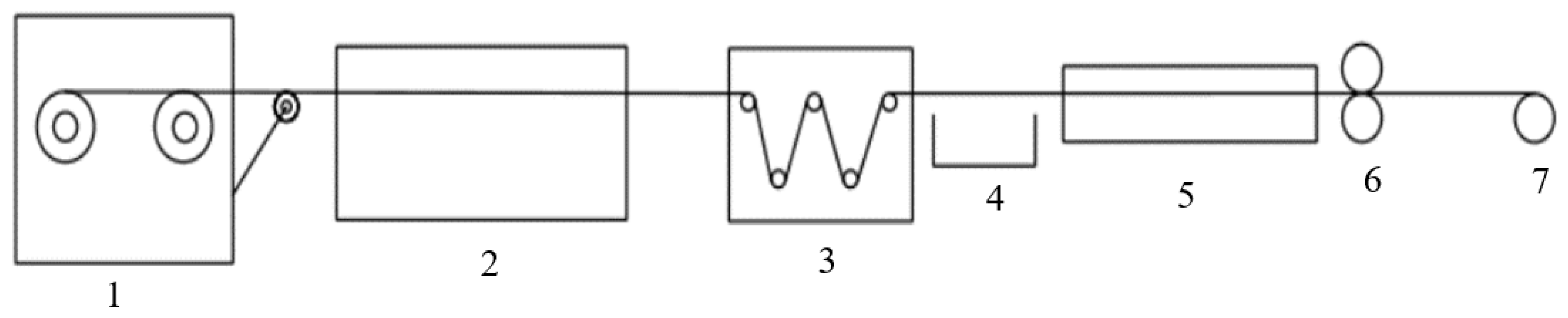
- Prepreg tape preparation: Place the fibers in the order of yarn frame, pre-dispersion mold, dipping tank, mold and three-roll calender, turn on the control cabinet to heat the mold and after the set temperature is reached, add slurry to the dipping tank and circulate to ensure that the suspension is not deposited. Turn on the calender, cool the prepared prepreg tape and roll it. Figure 1 shows the flow chart of CNT/CCF/PEKK prepreg tape preparation.
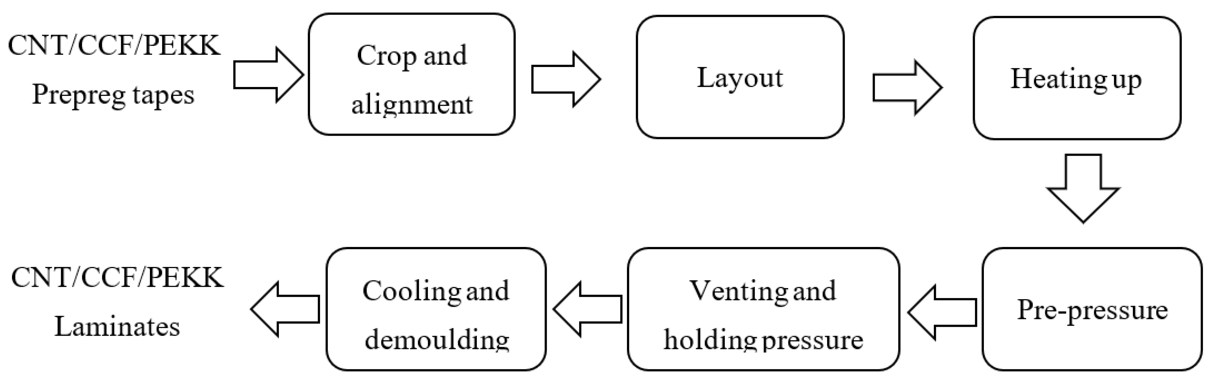
2.3. Laminate Preparation
2.4. Measurements
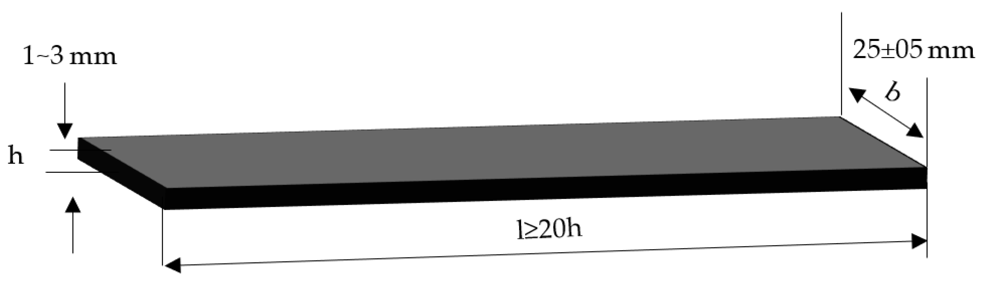
2.4.1. Flexural Strength Test
2.4.2. In-Surface Thermal Conductivity
2.4.3. Electrical Conductivity
2.4.4. Interlaminar Shear Strength
2.4.5. DSC
2.4.6. DMA
3. Results and Discussion
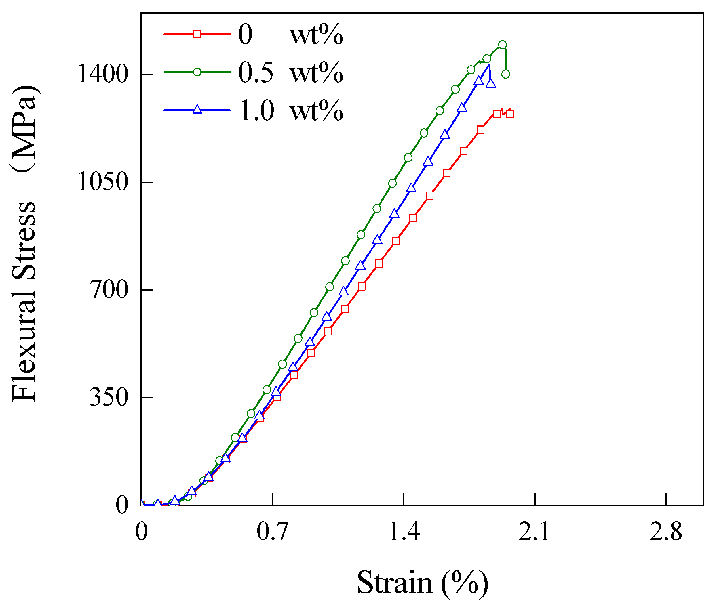
3.1. Flexural Strength
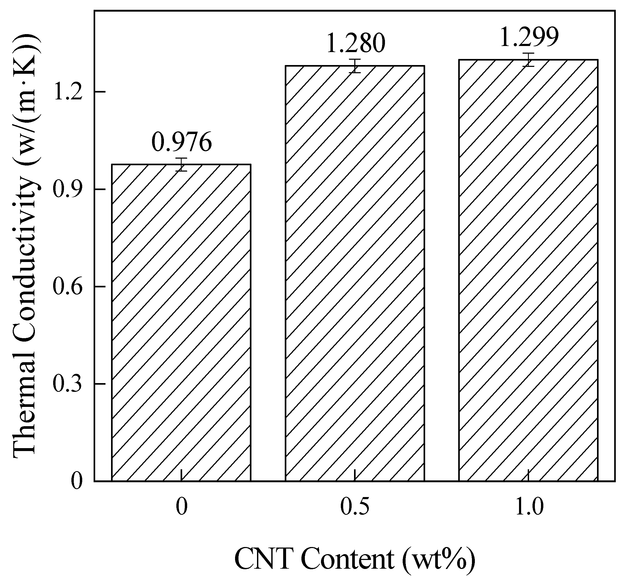
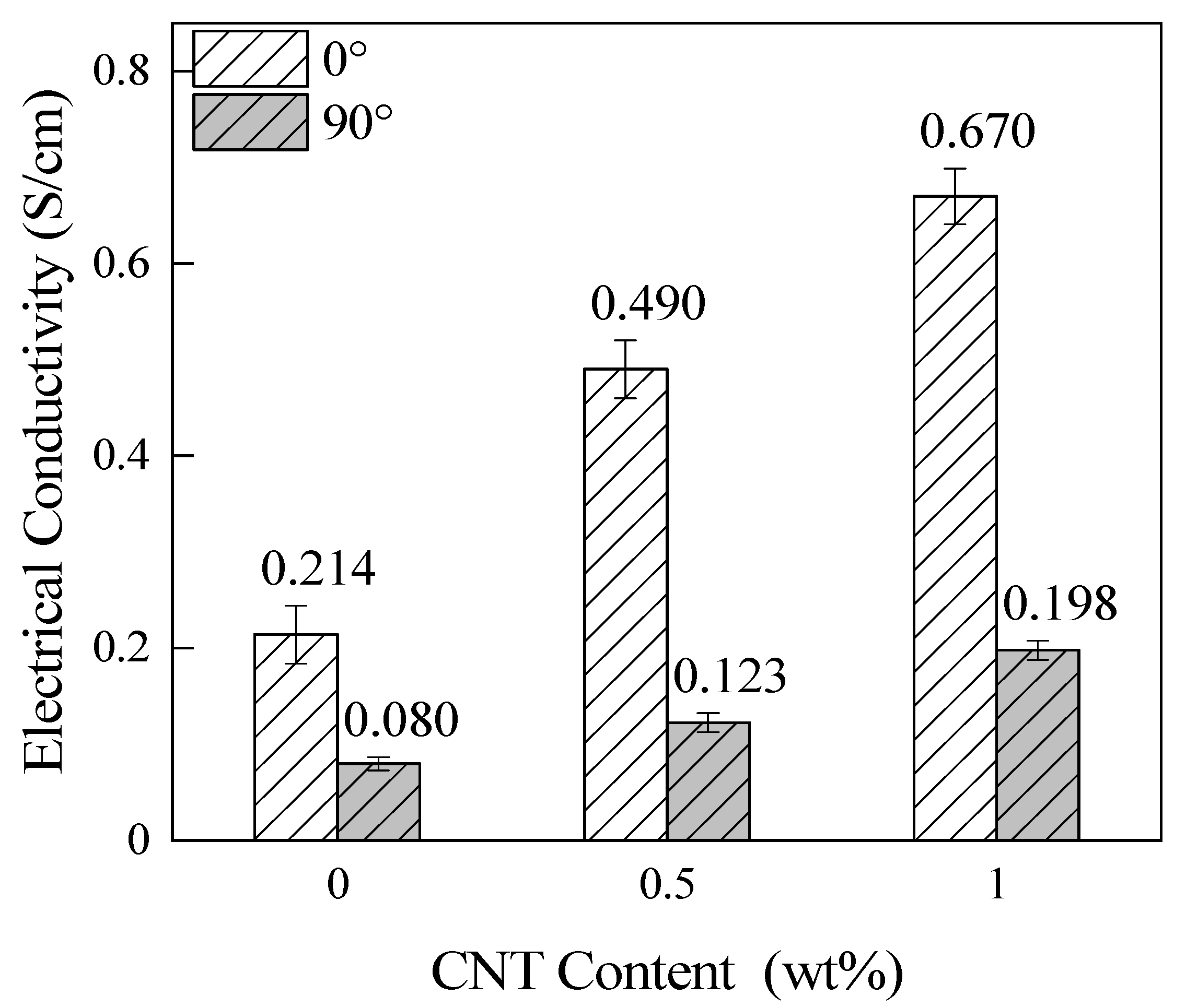
3.2. In-Surface Thermal Conductivity and Electrical Conductivity
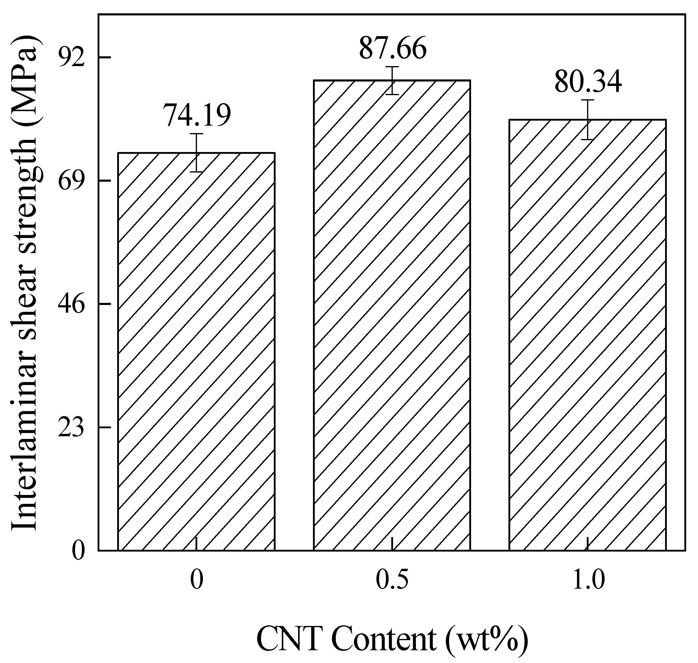
3.3. Interlaminar Shear Strength
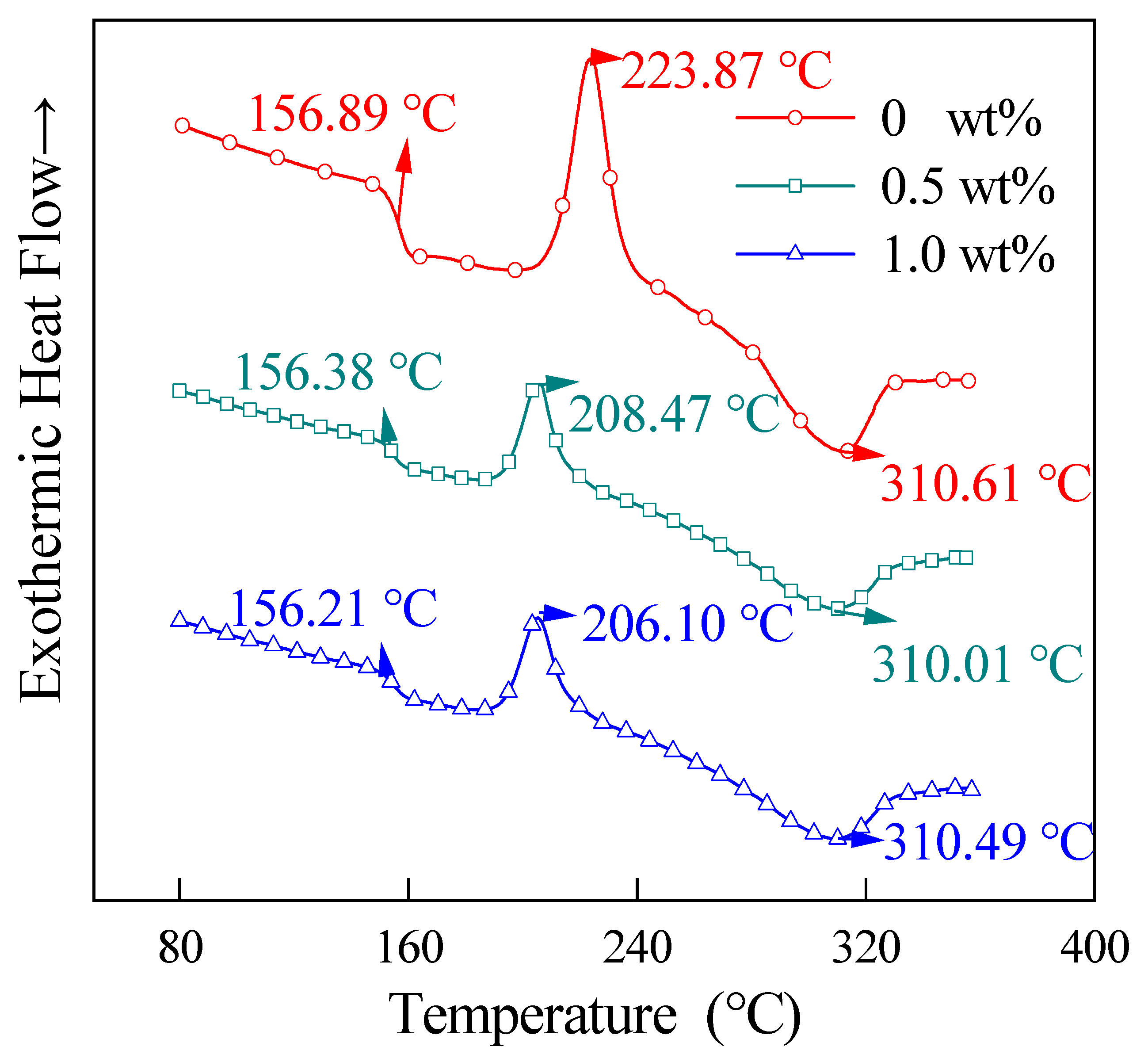
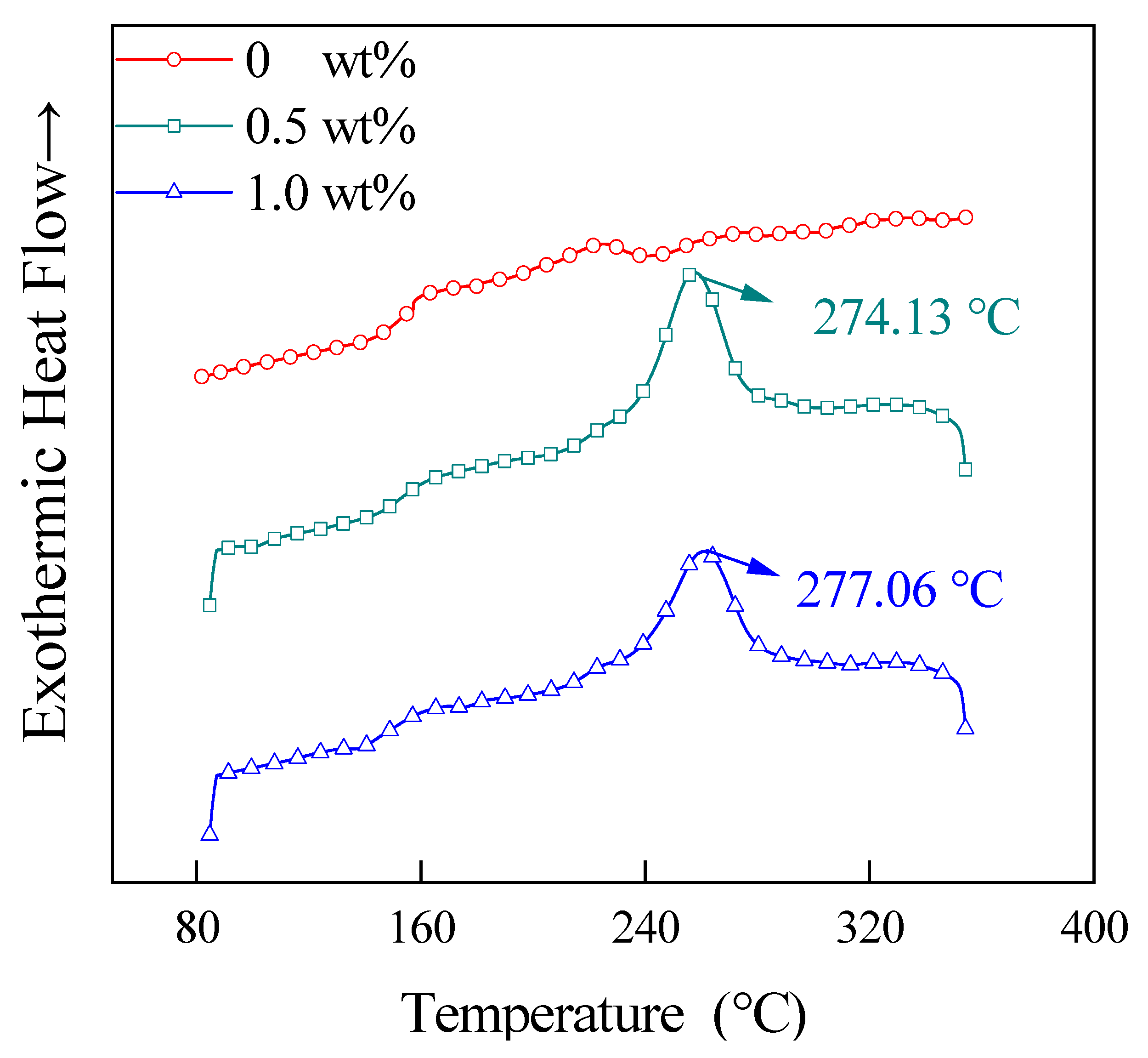
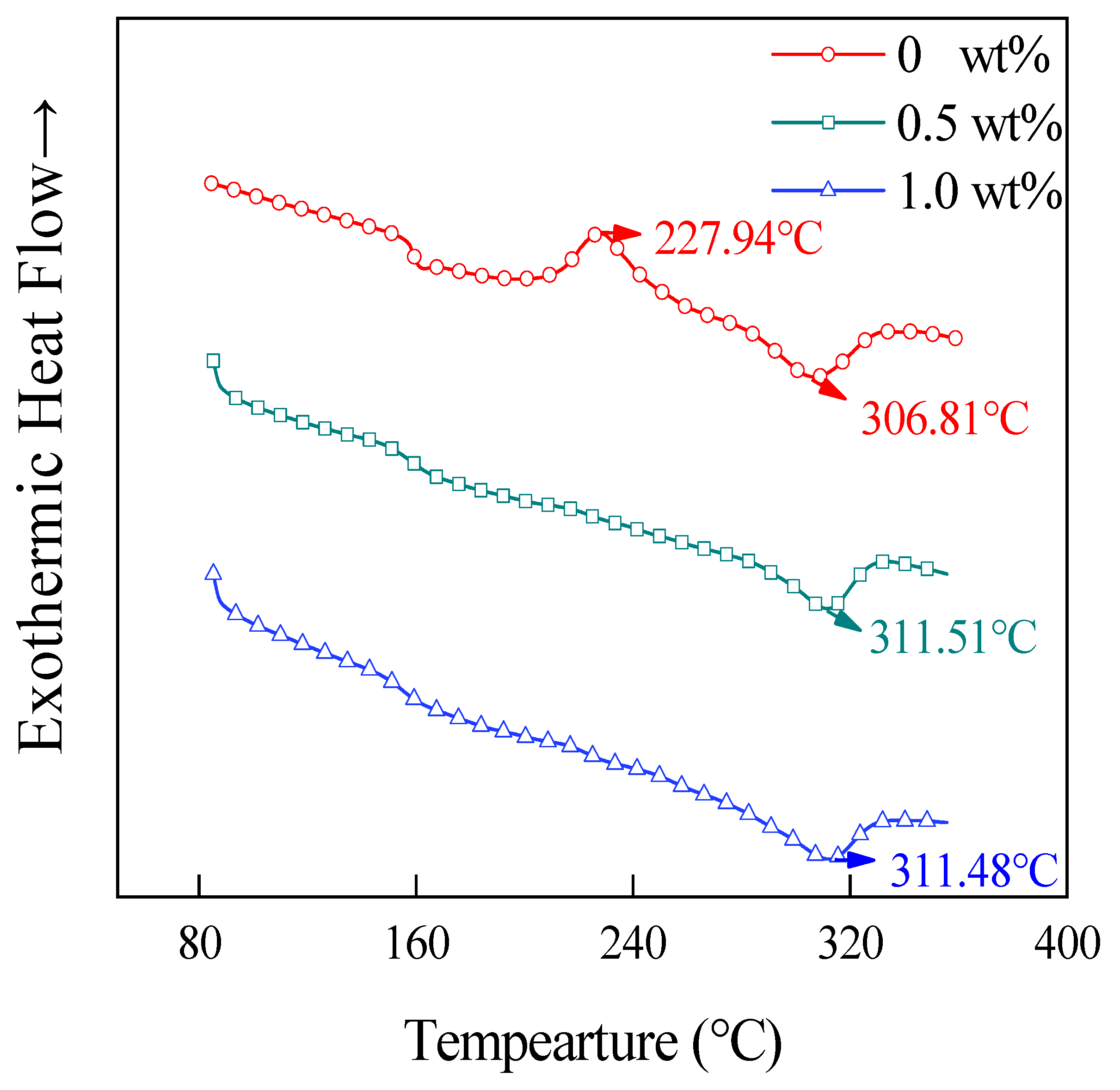
3.4. DSC Analysis
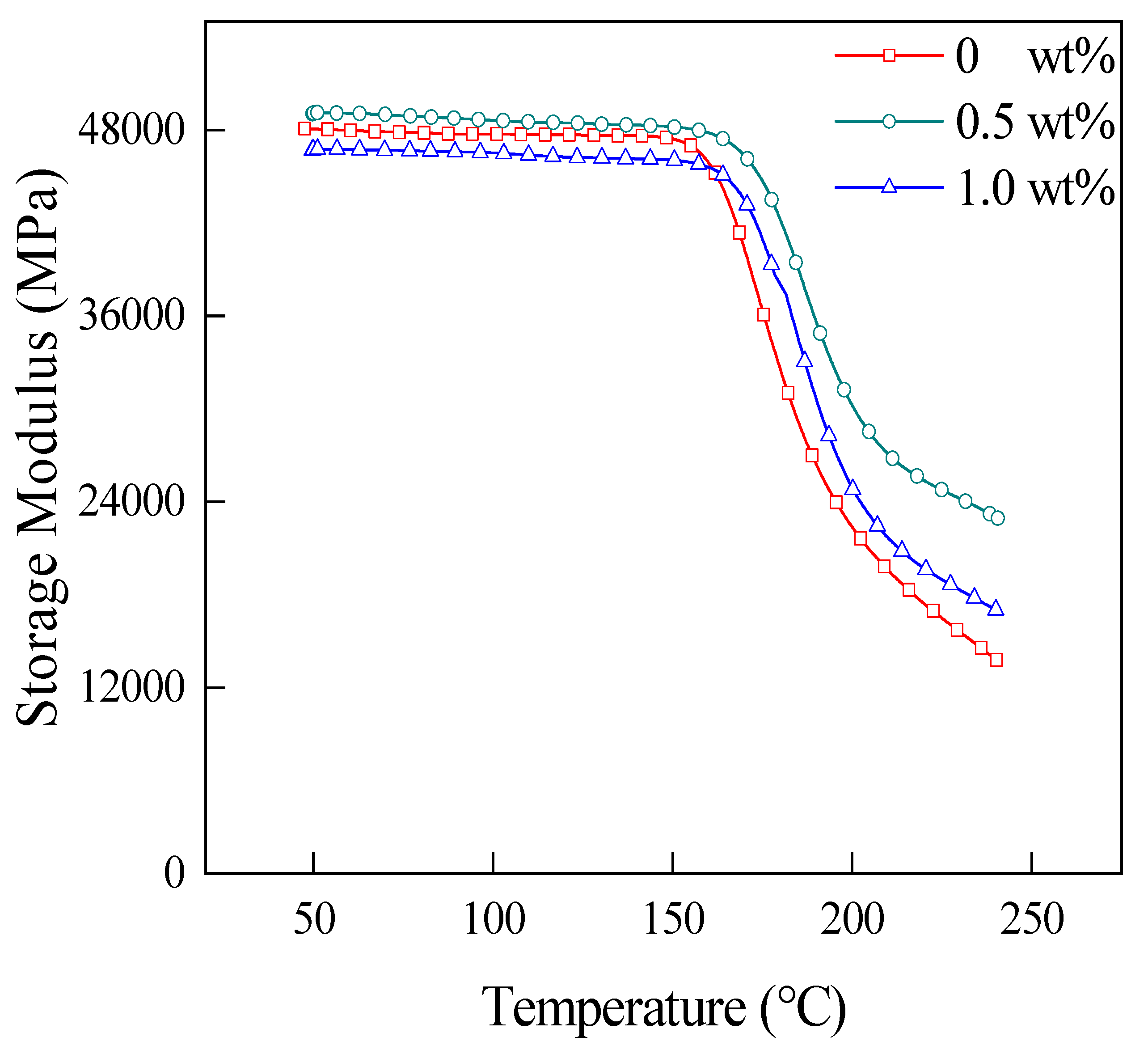
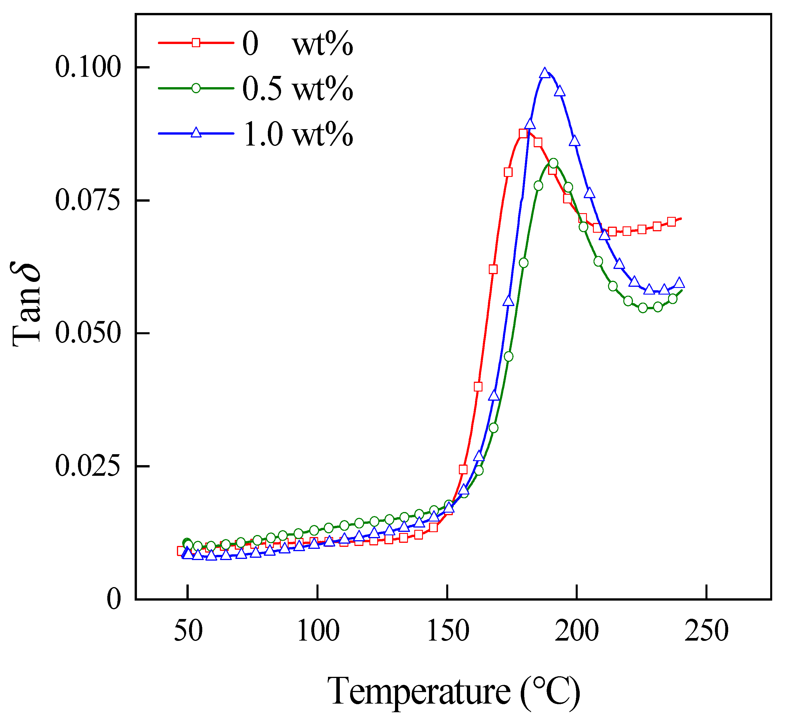
3.5. DMA
4. Conclusions
- (1)
- An appropriate amount of CNT can improve the adhesion between CF and PEKK and increase the flexural strength and ILSS of CNT/CCF/PEKK laminates. In this study, the 0.5 wt% CNT-content laminate has higher flexural strength and ILSS. When the CNT content increases to 1.0 wt%, the flexural strength and ILSS of the laminate decrease.
- (2)
- CNT can form a perfect transmission network of phonons and electrons inside the material. In the range of 0–1.0 wt%, the higher the CNT content, the better the conductivity and thermal conductivity of the material.
- (3)
- CNT can form a perfect crystallization network in the material, and PEKK can crystallize at a higher fiber content. In addition, CNT plays the role of heterogeneous nucleation in the material. In the range of 0–1.0 wt%, the higher the CNT content, the more crystalline nuclei, and the faster the PEKK crystallization rate. When CNT content is 0.5 wt%, PEKK crystallinity is higher, and when CNT content increases to 1.0 wt%, PEKK crystallinity decreases.
- (4)
- An appropriate amount of CNT can improve the storage modulus of the laminates, the adhesion between CF and PEKK, and Tg. In this work, 0.5 wt% CNT-content laminates have higher storage modulus, lower tanδ peaks and higher Tg.
Author Contributions
Funding
Institutional Review Board Statement
Informed Consent Statement
Data Availability Statement
Conflicts of Interest
References
- Rahmani, H.; Najaf, S.H.M.; Ashori, A.; Golriz, M. Elastic properties of carbon fibre-reinforced epoxy composites. Polym. Polym. Compos. 2015, 23, 475–482. [Google Scholar] [CrossRef]
- Choupin, T.; Fayolle, B.; Régnier, G.; Paris, C.; Cinquin, J.; Brulé, B. A more reliable DSC-based methodology to study crystallization kinetics: Application to poly (ether ketone ketone) (PEKK) copolymers. Polymer 2018, 155, 109–115. [Google Scholar] [CrossRef] [Green Version]
- Shams, S.S.; El-Hajjar, R.F. Overlay patch repair of scratch damage in carbon fiber/epoxy laminated composites. Compos. Part A Appl. Sci. Manuf. 2013, 49, 148–156. [Google Scholar] [CrossRef]
- Wang, F.S.; Ji, Y.Y.; Yu, X.S.; Chen, H.; Yue, Z.F. Ablation damage assessment of aircraft carbon fiber/epoxy composite and its protection structures suffered from lightning strike. Compos. Struct. 2016, 145, 226–241. [Google Scholar] [CrossRef]
- Cheng, K.-J.; Liu, Y.-F.; Wang, R.; Zhang, J.-X.; Jiang, X.-F.; Dong, X.-T.; Xu, X. Topological optimization of 3D printed bone analog with PEKK for surgical mandibular reconstruction. J. Mech. Behav. Biomed. Mater. 2020, 107, 103758. [Google Scholar] [CrossRef]
- Xiao, F.; Zhai, Y.; Zhou, Y.; Xu, X.; Liu, Y.; Ma, X.; Gu, X.; Wang, W. Low-temperature fabrication of titania layer on 3D-printed PEKK for enhancing biocompatibility. Surf. Coat. Technol. 2021, 416, 127158. [Google Scholar] [CrossRef]
- Alqurashi, H.; Khurshid, Z.; Syed, A.U.Y.; Habib, S.R.; Rokaya, D.; Zafar, M.S. Polyetherketoneketone (PEKK): An emerging biomaterial for oral implants and dental prostheses. J. Adv. Res. 2021, 28, 87–95. [Google Scholar] [CrossRef] [PubMed]
- Fokas, G.; Guo, C.Y.; Tsoi, J.K. The effects of surface treatments on tensile bond strength of polyether-ketone-ketone (PEKK) to veneering resin. J. Mech. Behav. Biomed. Mater. 2019, 93, 1–8. [Google Scholar] [CrossRef]
- Sun, S.; Jin, Z.; Liu, X.; Han, Z.; Wang, Y. In situ consolidation process-based fabrication and interlaminar modification mechanism associated with CF/PEEK multiscale nanocomposites characterized by interlaminar doping of CNTs. Compos. Sci. Technol. 2022, 222, 109356. [Google Scholar] [CrossRef]
- Zhang, D.; Huang, Y. The bonding performances of carbon nanotube (CNT)-reinforced epoxy adhesively bonded joints on steel substrates. Prog. Org. Coat. 2021, 159, 106407. [Google Scholar] [CrossRef]
- He, Y.; Zhang, J.; Yao, L.; Tang, J.; Che, B.; Ju, S.; Jiang, D. A multi-layer resin film infusion process to control CNTs distribution and alignment for improving CFRP interlaminar fracture toughness. Compos. Struct. 2021, 260, 113510. [Google Scholar] [CrossRef]
- Yildiz, K.; Gürkan, İ.; Turgut, F.; Cebeci, F.Ç.; Cebeci, H. Fracture toughness enhancement of fuzzy CNT-glass fiber reinforced composites with a combined reinforcing strategy. Compos. Commun. 2020, 21, 100423. [Google Scholar] [CrossRef]
- Szatkowski, P.; Czechowski, L.; Gralewski, J.; Szatkowska, M. Mechanical Properties of Polylactide Admixed with Carbon Nanotubes or Graphene Nanopowder. Materials 2021, 14, 5955. [Google Scholar] [CrossRef]
- Ashrafi, B.; Díez-Pascual, A.M.; Johnson, L.; Genest, M.; Hind, S.; Martinez-Rubi, Y.; González-Domínguez, J.M.; Martínez, M.T.; Simard, B.; Gómez-Fatou, M.A.; et al. Processing and properties of PEEK/glass fiber laminates: Effect of addition of single-walled carbon nanotubes. Compos. Part A Appl. Sci. Manuf. 2012, 43, 1267–1279. [Google Scholar] [CrossRef]
- Qiao, L.; Zhu, K.; Tan, H.; Yan, X.; Zheng, L.; Dong, S. Effect of carbon nanotubes on the electrical, thermal, mechanical properties and crystallization behavior of continuous carbon fiber reinforced polyether-ether-ketone composites. Mater. Res. Express 2021, 8, 045312. [Google Scholar] [CrossRef]
- Rojas, J.A.; Ribeiro, B.; Rezende, M.C. Influence of serrated edge and rectangular strips of MWCNT buckypaper on the electromagnetic properties of glass fiber/epoxy resin composites. Carbon 2020, 160, 317–327. [Google Scholar] [CrossRef]
- Santos, L.F.D.P.; Alderliesten, R.; Kok, W.; Ribeiro, B.; de Oliveira, J.B.; Costa, M.L.; Botelho, E.C. The influence of carbon nanotube buckypaper/poly (ether imide) mats on the thermal properties of poly (ether imide) and poly (aryl ether ketone)/carbon fiber laminates. Diam. Relat. Mater. 2021, 116, 108421. [Google Scholar] [CrossRef]
- Marathe, U.; Padhan, M.; Bijwe, J. Carbon nanotubes-a powerful nano-filler for enhancing the performance properties of polyetherketoneketone composites and adhesives. Compos. Sci. Technol. 2021, 210, 108813. [Google Scholar] [CrossRef]
- Lyu, H.; Jiang, N.; Li, Y.; Zhang, D. Enhancing CF/PEEK interfacial adhesion by modified PEEK grafted with carbon nanotubes. Compos. Sci. Technol. 2021, 210, 108831. [Google Scholar] [CrossRef]
- Luo, Q.; Wang, M.; Zhang, H.; Ouyang, Y.; Lin, H.; Shu, Y.; Su, S. Preparation and properties of bio-based flame retardant L-APP/poly (L-lactic acid) composites. J. Renew. Mater. 2021, 9, 2067–2076. [Google Scholar] [CrossRef]
- Su, C.; Wang, X.; Ding, L.; Yu, P. Enhancement of mechanical behavior of resin matrices and fiber reinforced polymer composites by incorporation of multi-wall carbon nanotubes. Polym. Test. 2021, 96, 107077. [Google Scholar] [CrossRef]
- Sanivada, U.K.; Esteves, D.; Arruda, L.M.; Silva, C.A.; Moreira, I.P.; Fangueiro, R. Joule-Heating Effect of Thin Films with Carbon-Based Nanomaterials. Materials 2022, 15, 4323. [Google Scholar] [CrossRef]
- Yousefi, N.; Fisher, S.J.; Burgstaller, C.; Shaffer, M.S.; Bismarck, A. Hierarchical carbon fibre composites incorporating high loadings of carbon nanotubes. Compos. Sci. Technol. 2022, 222, 109369. [Google Scholar] [CrossRef]
- Ogasawara, T.; Tsuda, T.; Takeda, N. Stress–strain behavior of multi-walled carbon nanotube/PEEK composites. Compos. Sci. Technol. 2011, 71, 73–78. [Google Scholar] [CrossRef]
- Kennedy, Z.C.; Christ, J.F.; Fenn, M.D.; Zhong, L.; Chouyyok, W.; Arnold, A.W.; Denny, A.C.; Albrecht, A.M.; Silverstein, J.A.; Erikson, R.L. Mica filled polyetherketoneketones for material extrusion 3D printing. Addit. Manuf. 2022, 49, 102492. [Google Scholar] [CrossRef]
- Perez-Martin, H.; Mackenzie, P.; Baidak, A.; Brádaigh, C.M.Ó.; Ray, D. Crystallinity studies of PEKK and carbon fibre/PEKK composites: A review. Compos. Part B Eng. 2021, 223, 109127. [Google Scholar] [CrossRef]
- Yan, X.; Liu, C.; Qiao, L.; Zhu, K.; Tan, H.; Dong, S.; Lin, Z. Crystallization and Dynamic Mechanical Behavior of Coir Fiber Reinforced Poly (Butylene Succinate) Biocomposites. J. Renew. Mater. 2022, 10, 1039–1048. [Google Scholar] [CrossRef]


| CNT Contents (wt%) | Tcc (°C) | Tm (°C) | Tc (°C) | ΔHm (J/g) | ΔHcc (J/g) | Χc (%) | t1/2 (min) |
|---|---|---|---|---|---|---|---|
| 0 | 227.94 | 306.81 | - | 7.45 | 4.25 | 2.46 | - |
| 0.5% | - | 311.51 | 256.55 | 6.09 | - | 4.68 | 3.26 |
| 1.0 | - | 311.48 | 260.67 | 6.04 | - | 4.64 | 3.00 |
Publisher’s Note: MDPI stays neutral with regard to jurisdictional claims in published maps and institutional affiliations. |
© 2022 by the authors. Licensee MDPI, Basel, Switzerland. This article is an open access article distributed under the terms and conditions of the Creative Commons Attribution (CC BY) license (https://creativecommons.org/licenses/by/4.0/).
Share and Cite
Yan, X.; Qiao, L.; Tan, H.; Tan, H.; Liu, C.; Zhu, K.; Lin, Z.; Xu, S. Effect of Carbon Nanotubes on the Mechanical, Crystallization, Electrical and Thermal Conductivity Properties of CNT/CCF/PEKK Composites. Materials 2022, 15, 4950. https://doi.org/10.3390/ma15144950
Yan X, Qiao L, Tan H, Tan H, Liu C, Zhu K, Lin Z, Xu S. Effect of Carbon Nanotubes on the Mechanical, Crystallization, Electrical and Thermal Conductivity Properties of CNT/CCF/PEKK Composites. Materials. 2022; 15(14):4950. https://doi.org/10.3390/ma15144950
Chicago/Turabian StyleYan, Xu, Liang Qiao, Hao Tan, Hongsheng Tan, Changheng Liu, Kaili Zhu, Zhitao Lin, and Shanshan Xu. 2022. "Effect of Carbon Nanotubes on the Mechanical, Crystallization, Electrical and Thermal Conductivity Properties of CNT/CCF/PEKK Composites" Materials 15, no. 14: 4950. https://doi.org/10.3390/ma15144950