Figure 1.
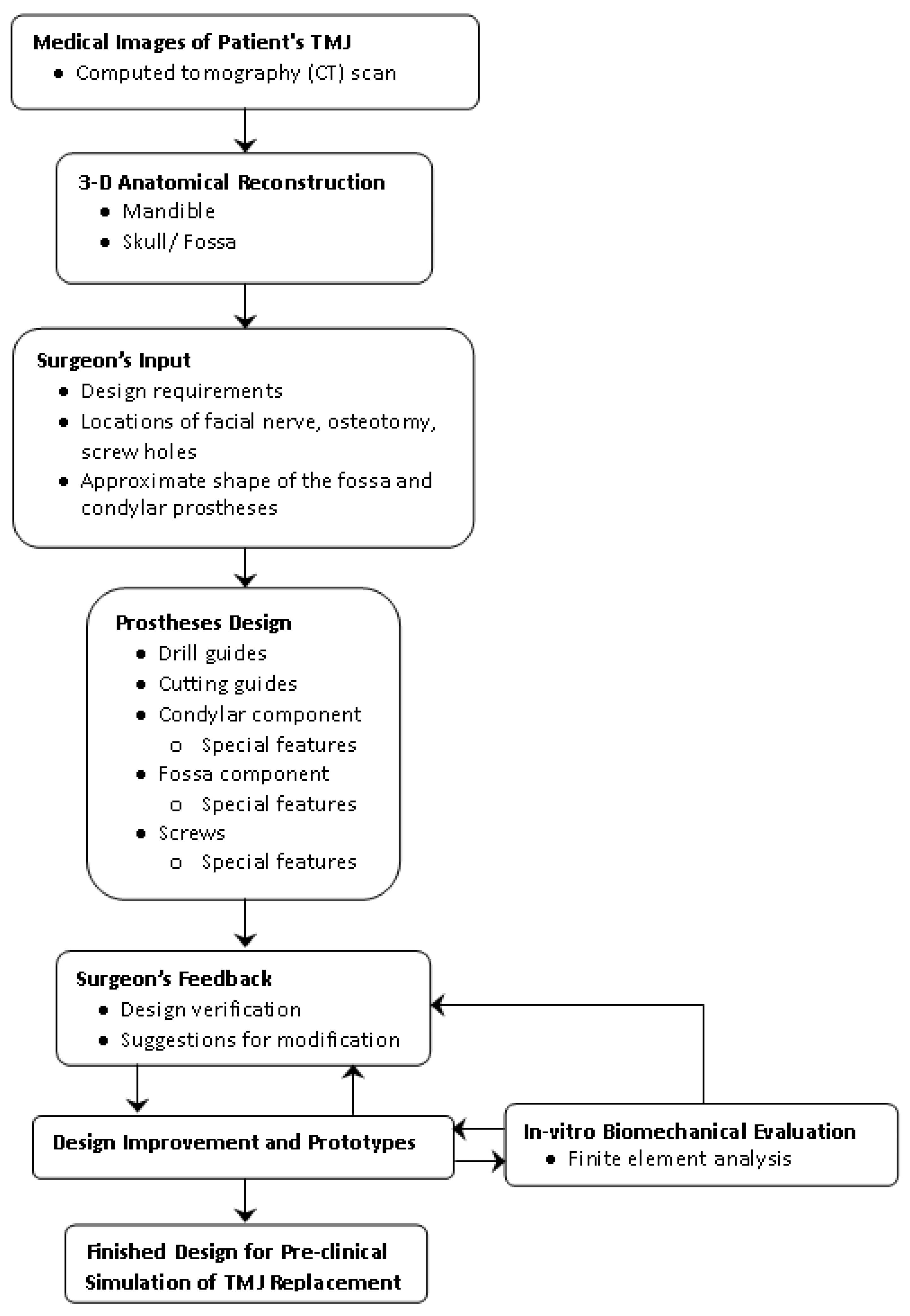
Methodology followed for design and preliminary analysis of the patient-specific total temporomandibular joint (TMJ) prostheses.
Figure 1.
Methodology followed for design and preliminary analysis of the patient-specific total temporomandibular joint (TMJ) prostheses.
Figure 2.
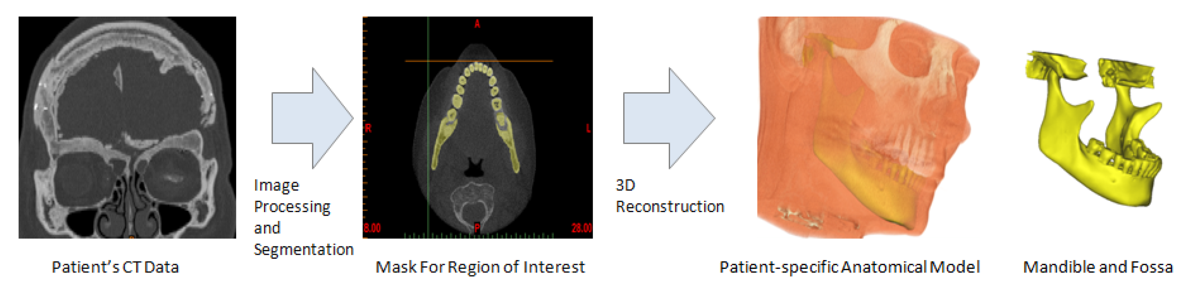
Subject-specific 3D anatomical reconstruction of the patient’s mandible and fossa eminence performed from computed tomography (CT) data using Mimics software.
Figure 2.
Subject-specific 3D anatomical reconstruction of the patient’s mandible and fossa eminence performed from computed tomography (CT) data using Mimics software.
Figure 3.
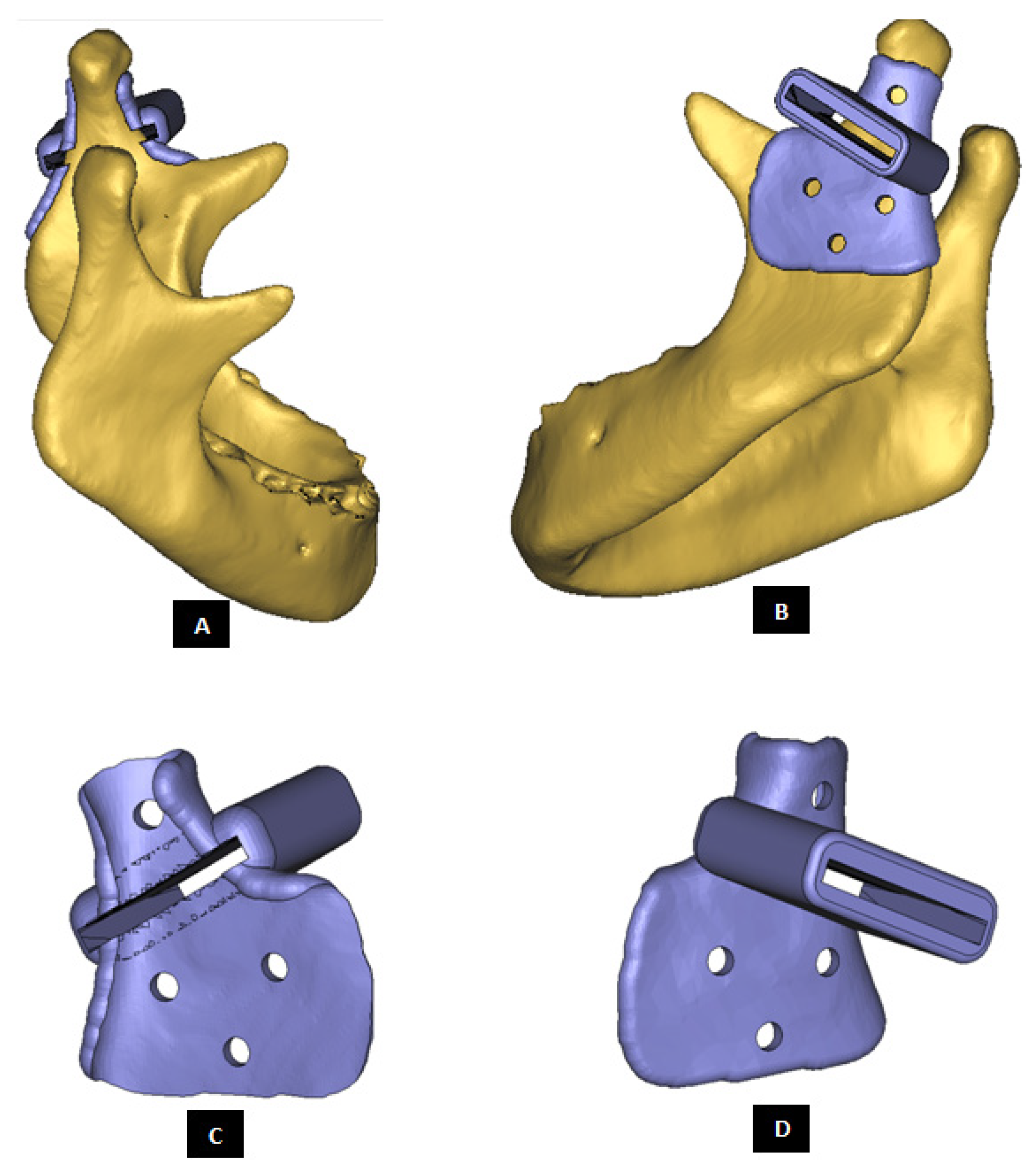
Custom-designed surgical guide for condylectomy (i.e., removal of damaged part of the condylar bone). (A,B) Show the medial and lateral view, respectively, of surgical guide placed at the location on mandible where osteotomy is to be performed. (C,D) Show medial and lateral–anterior view, respectively, of the surgical guide alone. The visuals demonstrate that custom-design of the device enables it to accurately adapt to the native bone. This methodology allows the designer to control size and shape of the device, and location of its fixation screws as prescribed by the surgeon.
Figure 3.
Custom-designed surgical guide for condylectomy (i.e., removal of damaged part of the condylar bone). (A,B) Show the medial and lateral view, respectively, of surgical guide placed at the location on mandible where osteotomy is to be performed. (C,D) Show medial and lateral–anterior view, respectively, of the surgical guide alone. The visuals demonstrate that custom-design of the device enables it to accurately adapt to the native bone. This methodology allows the designer to control size and shape of the device, and location of its fixation screws as prescribed by the surgeon.
Figure 4.
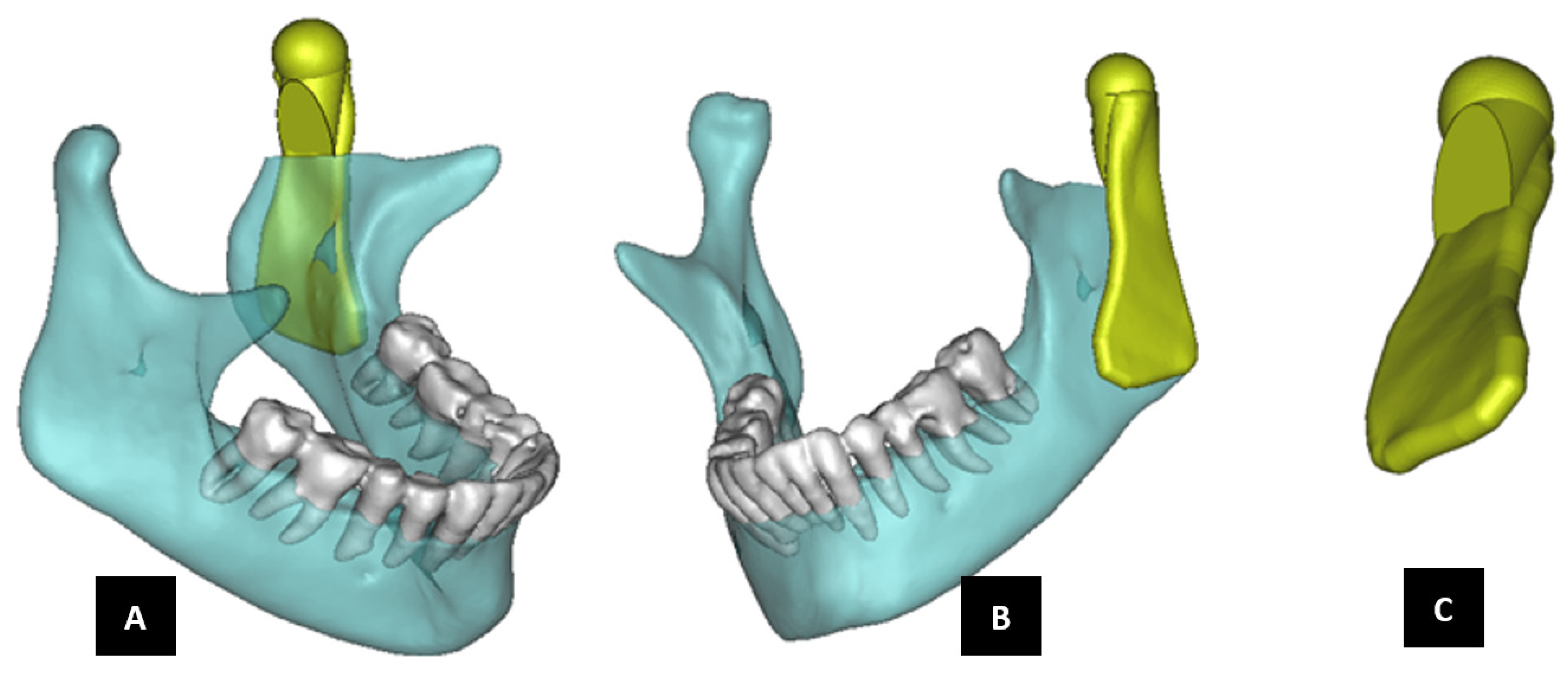
Shape outline of a custom-designed condylar/ramus prosthesis. (A,B) Show medial–anterior view and lateral–anterior view, respectively, of the prosthesis accurately adapting to the host bone. (C) Shows medial-inferior view of the prosthesis shape outline.
Figure 4.
Shape outline of a custom-designed condylar/ramus prosthesis. (A,B) Show medial–anterior view and lateral–anterior view, respectively, of the prosthesis accurately adapting to the host bone. (C) Shows medial-inferior view of the prosthesis shape outline.
Figure 5.
Shape outline of a custom-designed condylar/ramus prosthesis for the replacement of right TMJ of a patient. (A,B) Show lateral–anterior view and lateral–posterior view, respectively, of the prosthesis accurately conforming to geometric shape of patient’s mandible.
Figure 5.
Shape outline of a custom-designed condylar/ramus prosthesis for the replacement of right TMJ of a patient. (A,B) Show lateral–anterior view and lateral–posterior view, respectively, of the prosthesis accurately conforming to geometric shape of patient’s mandible.
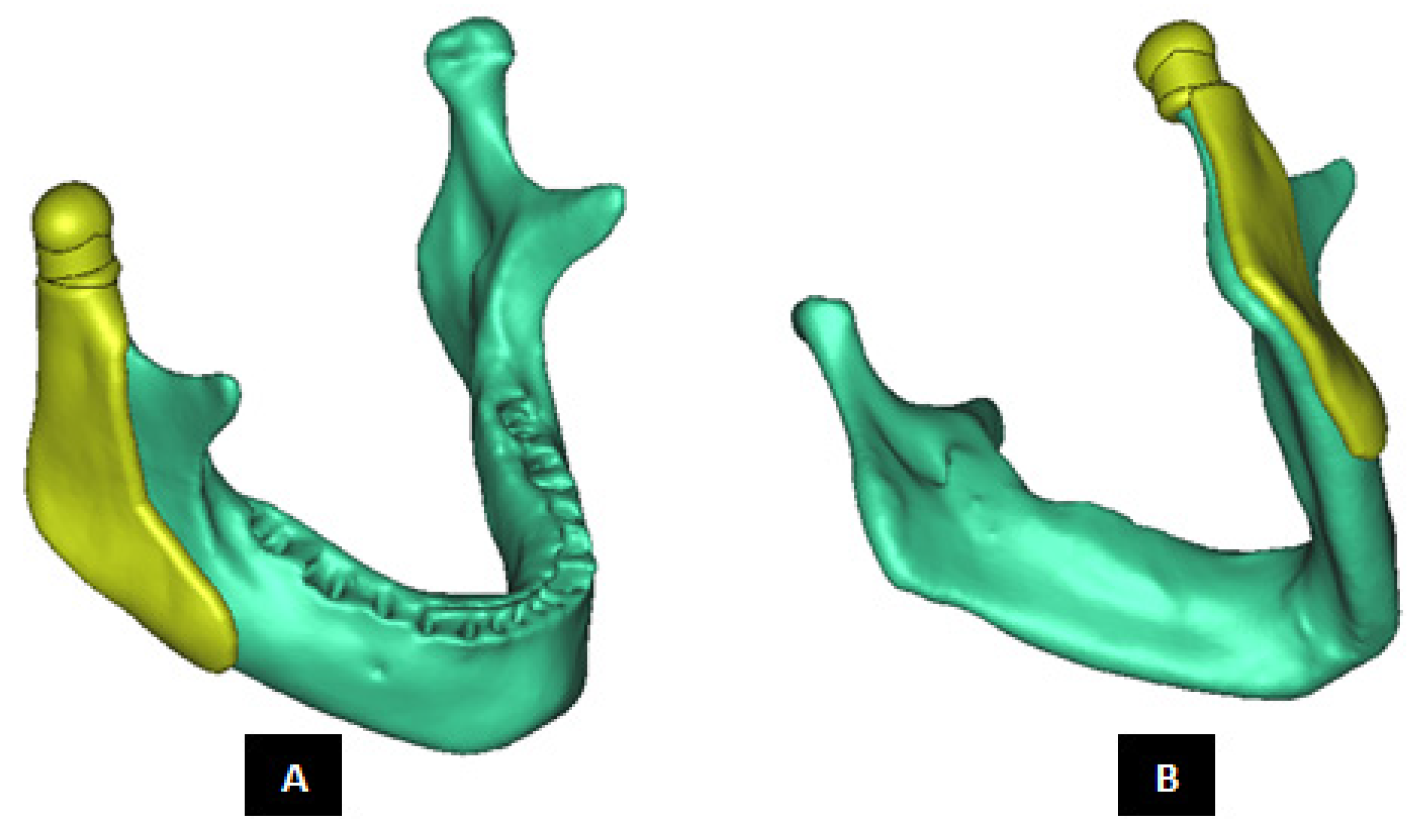
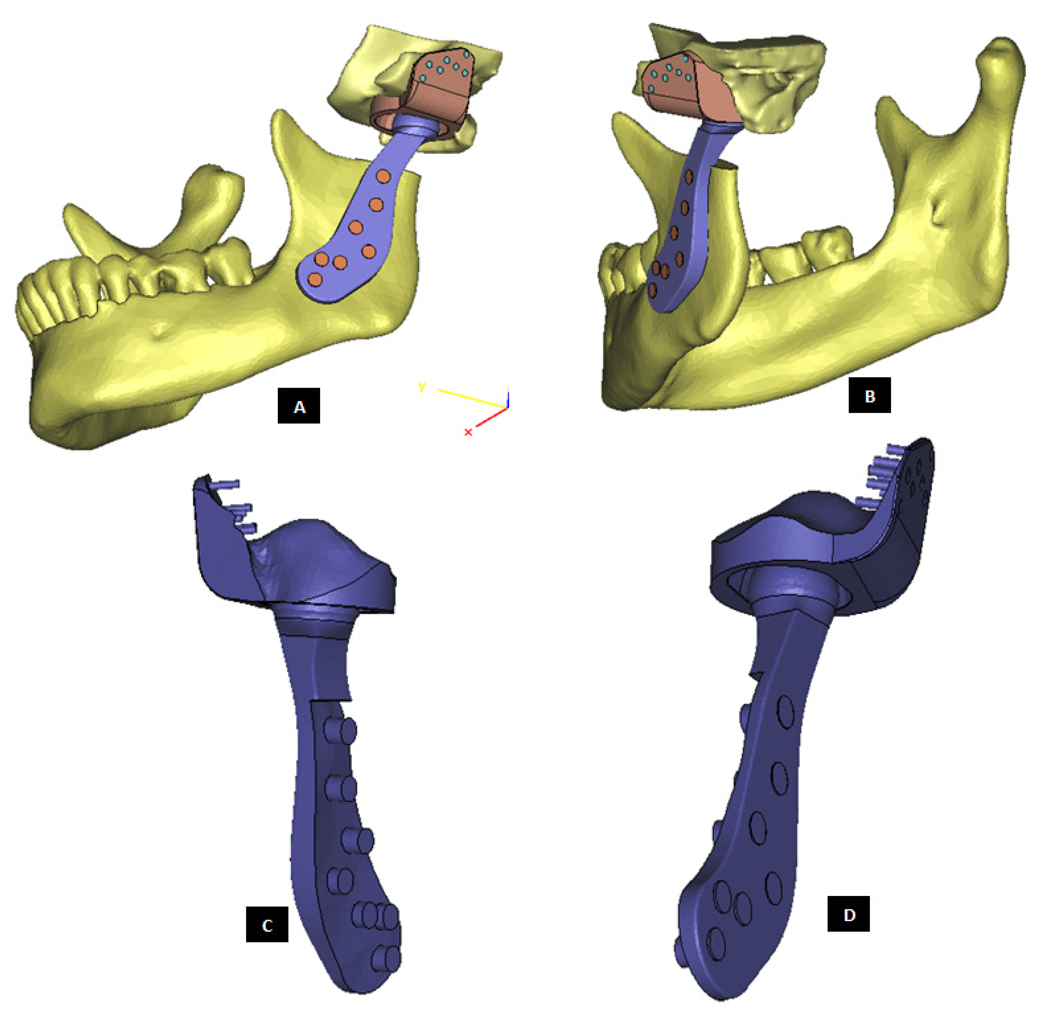
Figure 6.
Shape outline of a custom-designed condylar/ramus/mandibular component of the TMJ prosthesis for reconstruction of left TMJ. (A,B) Show medial–anterior view and lateral–anterior view, respectively, of the prosthesis along with 3D anatomical model of the patient’s mandible after condylectomy. The osteotomy gap seen in the left mandibular body is due to removal of a tumor in that region. This osteotomy gap can be filled with a graft, and the mandibular component of this TMJ prosthesis is designed to provide mechanical support to the host bone and graft.
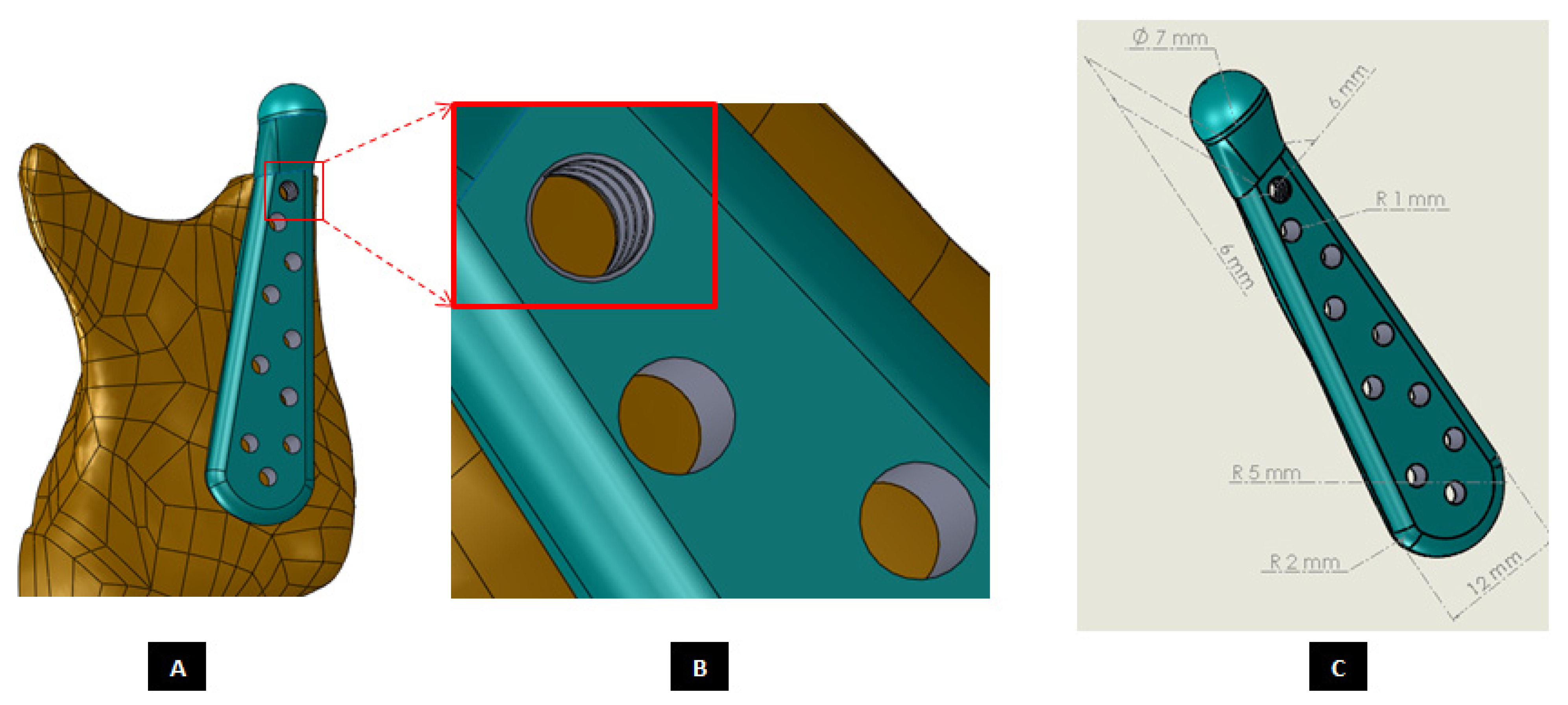
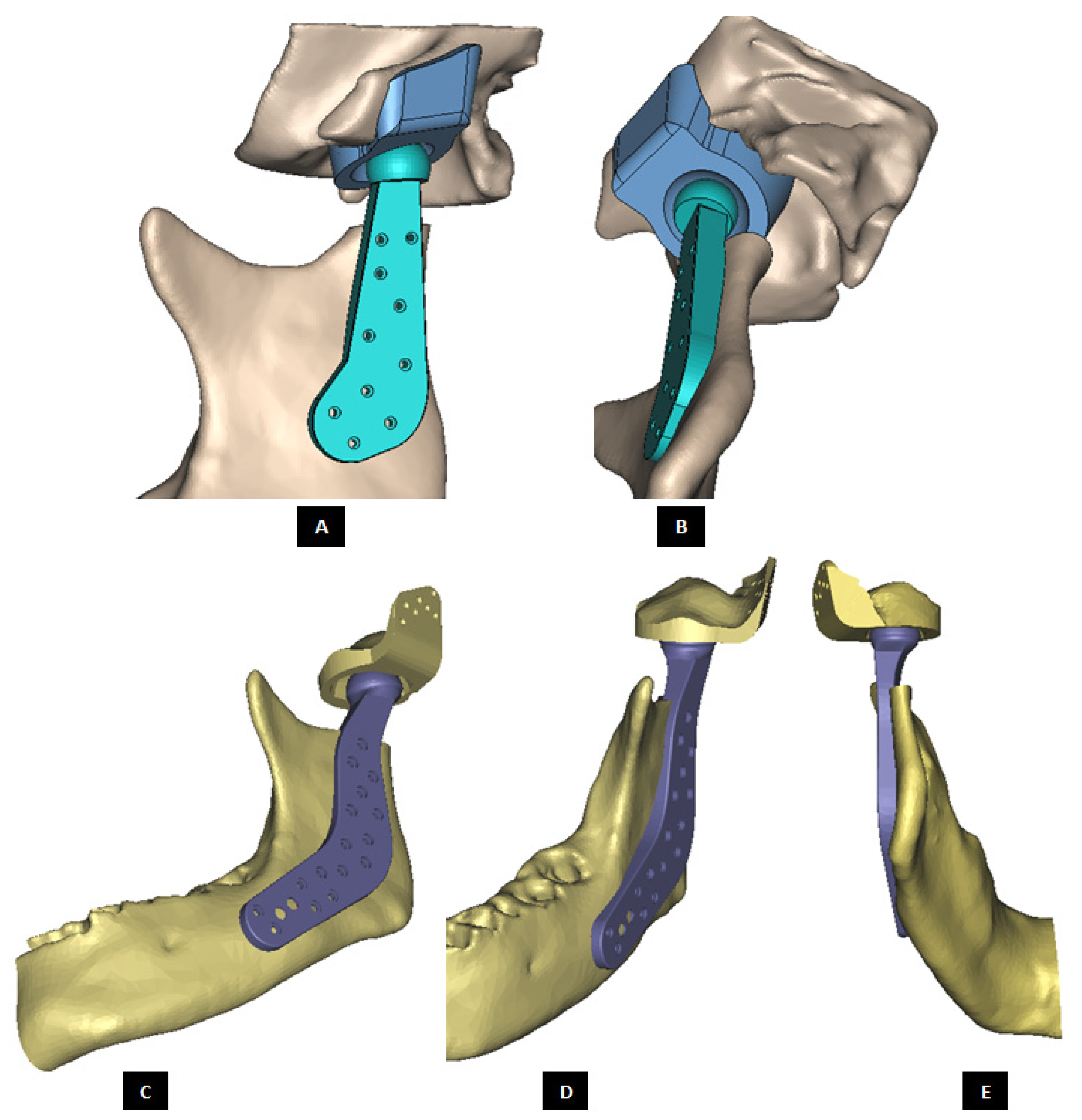
Figure 7.
Custom-designed condylar/ramus component of the TMJ total joint replacement prosthesis for left TMJ of a patient. (A) Shows lateral view of the implant with screw holes. (B) Shows an enlarged view of the screw holes, where the first superiorly located screw hole has threads to incorporate locking-plate-screw mechanism by engaging the threads on the head of a locking screw described in the text. (C) Shows engineering dimensions of this patient-specific implant.
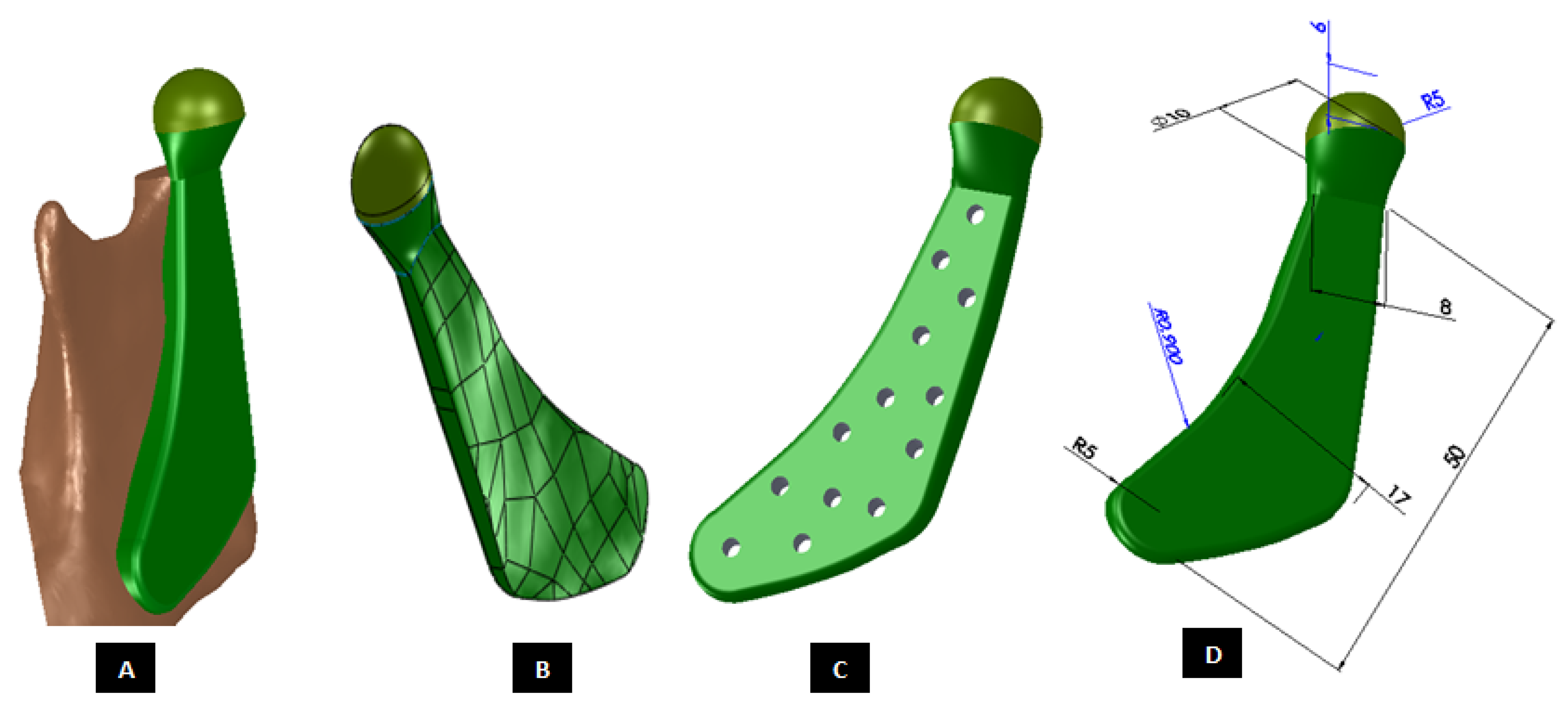
Figure 8.
Shape outline of a custom-designed condylar/ramus component of the TMJ total joint replacement prosthesis for left TMJ of a patient. (A) Shows anterior–lateral view of the implant with host bone after condylectomy. The posterior–medial view in (B) shows that the medial surface of prosthesis is shaped to accurately follow geometric contours of the lateral surface of mandibular host bone for optimal geometrical match between the implant and host bone. (C) Shows lateral view of the prosthesis with screw holes. Dimensions of various parts of this patient-specific implant are shown in (D).
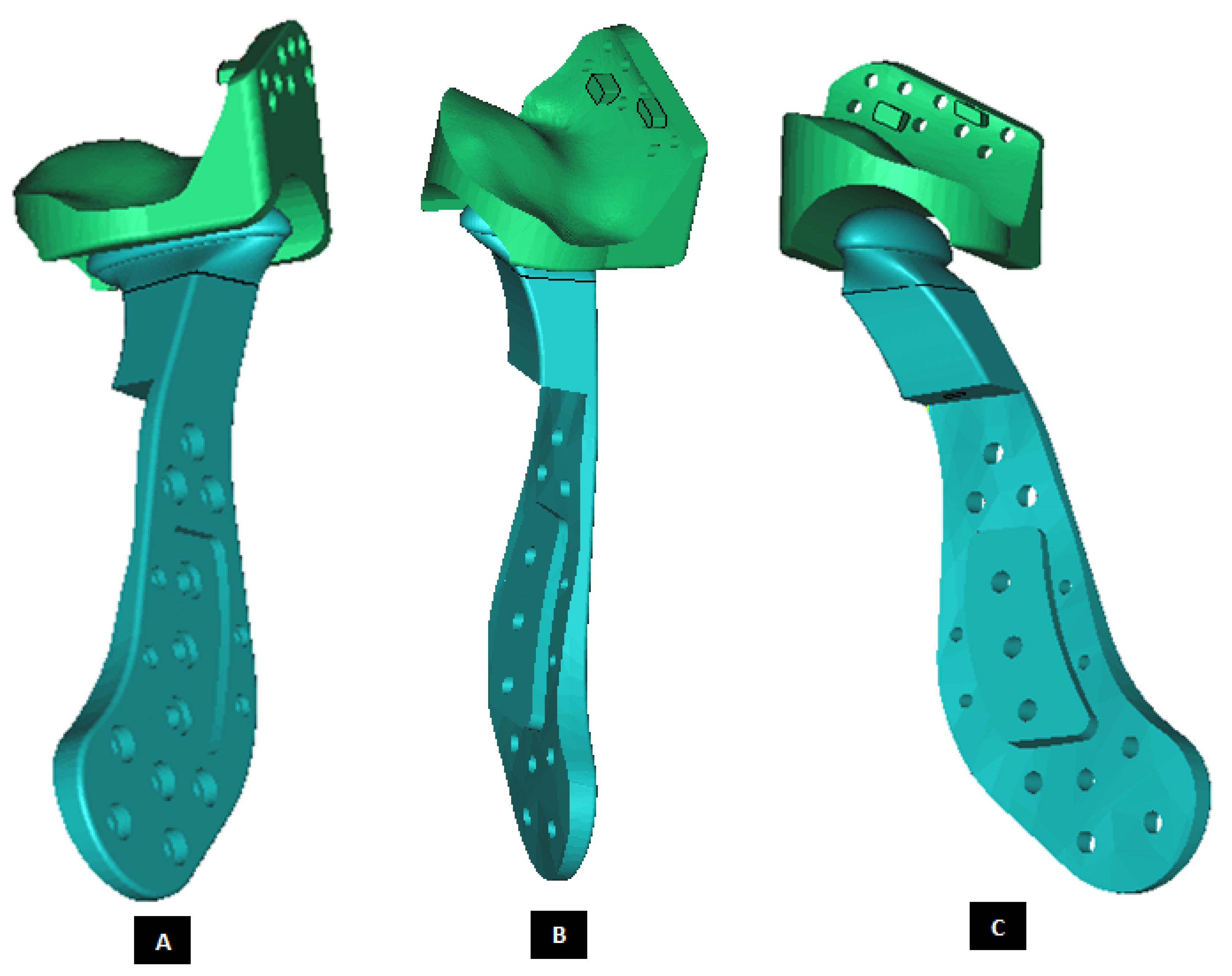
Figure 9.
Shape outline of a custom-designed condylar/ramus component of the TMJ total joint replacement prosthesis for left TMJ of a patient. Visuals in (A–E) demonstrate that shape of medial surface of the prosthesis accurately follows the geometric contours of the lateral surface of the mandibular host bone, and maximizes the opportunity for optimal adaptation of implant to the host bone. The lateral surface of the implant is flat, condylar head is spherical, and the condylar neck has a curvature to avoid problems seen in most right-angled designs of orthopaedic implants.
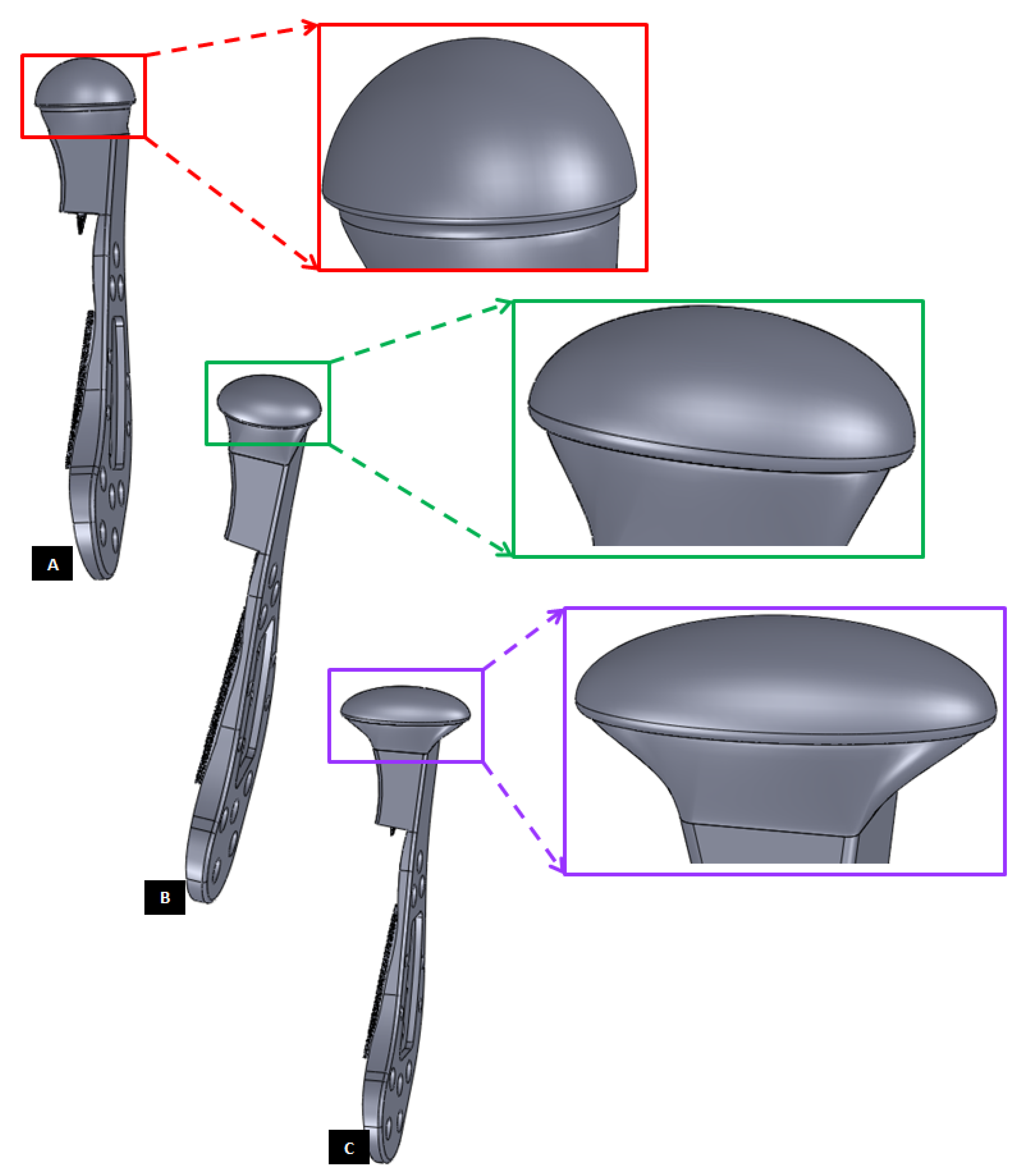
Figure 10.
Different shapes of the condylar head of the custom-designed condylar/ramus component of the TMJ prosthesis. (A) Shows a prosthesis with spherical condylar head. (B,C) Show prostheses with elliptical head of different dimensions. The condylar heads are designed to offer larger articulating surface area to avoid stress concentration at small area which may lead to more wear of the articulating surfaces of reconstructed TMJ.
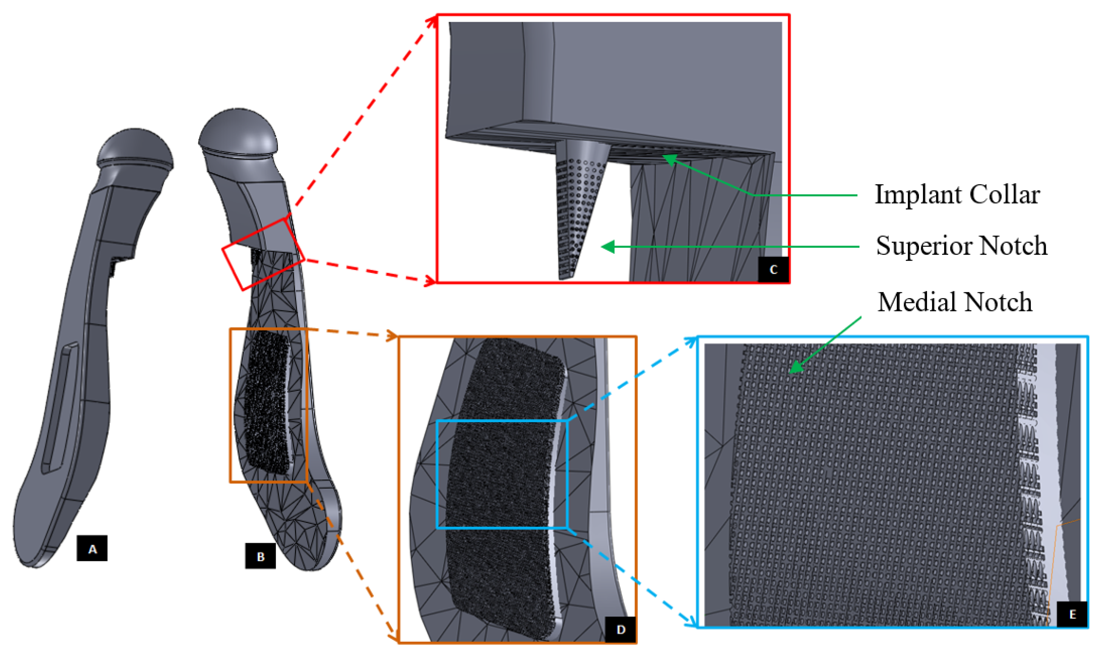
Figure 11.
Modification of the custom-designed condylar/ramus component, shown in
Figure 9, to include a novel feature; perforated notches protruding into host bone at implantation. (
A) Shows a grove in the flat lateral surface of the condylar implant. The opposite side of this grove, as shown in (
B), protrudes out of the medial surface as a notch with perforations. The enlarged views of medial notch and its perforations are shown in (
D,
E). The device also has pointed and perforated notch protruding from inferior surface of the implant’s collar/neck. Perforated surfaces of these notches are designed to permit bone in-growth into the prosthesis after implantation to provide added stability. Dimensions of these notches can be customized to fit the size and shape of patient’s native bone. Protrudes out of the medial surface as a notch with perforations (
C).
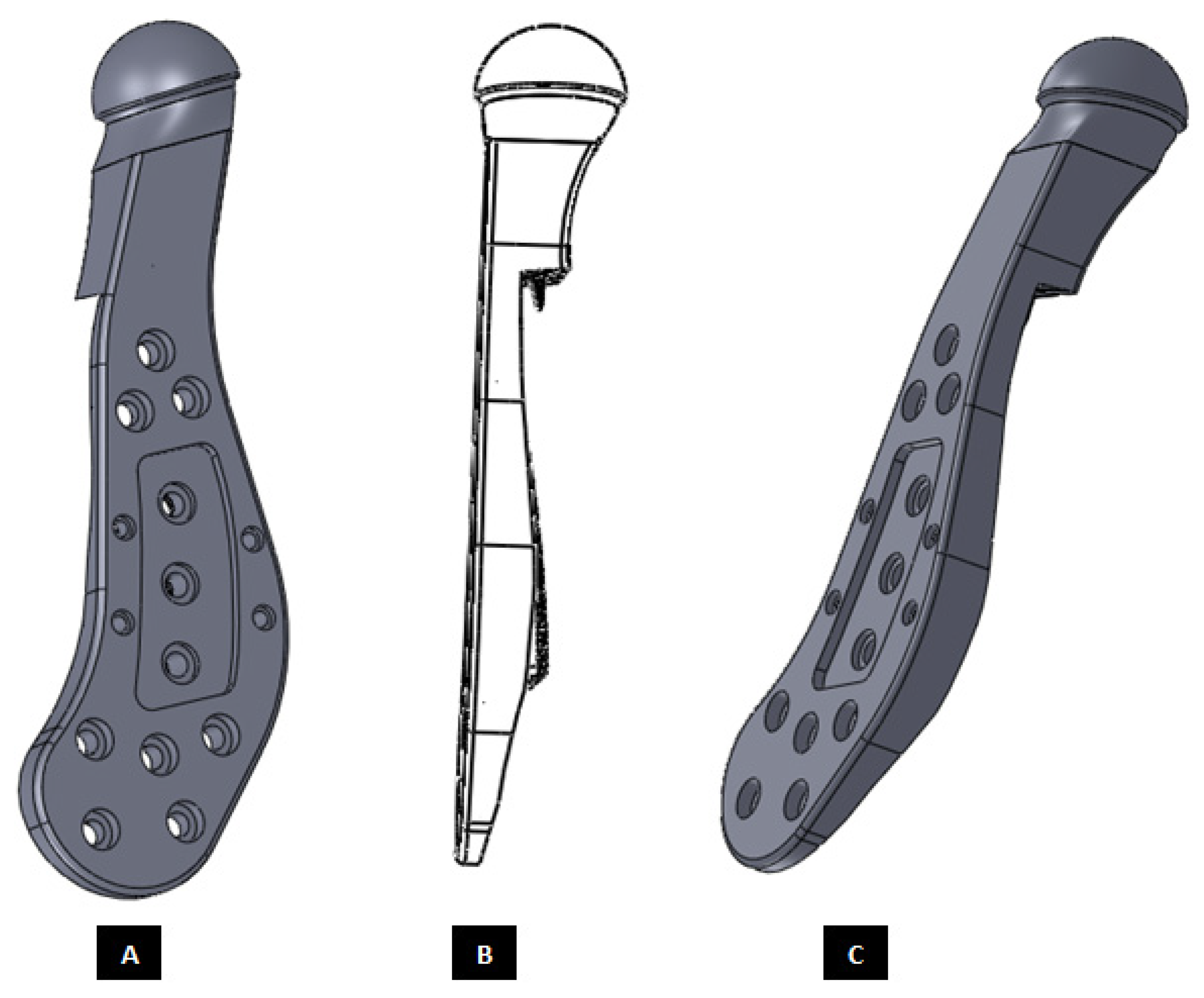
Figure 12.
Modification and refinement of custom-designed condylar/ramus component shown in
Figure 9 and
Figure 11. (
A,
C) Show pre-drilled screw holes and a grove in the lateral surface of implant. As shown in (
C), lateral surface of the device is flat and medial surface is shaped to match the host bone geometry. (
B) Shows a perforated notch each protruding from the medial surface of the ramus and inferior surface of the implant collar/neck.
Figure 13.
A simple custom-design of the fossa prosthesis with screw holes. (A) Demonstrates that the implant is designed for optimal usage of natural fossa eminence for fixation using screws. (B,C) Show different views of the implant illustrating the custom shape accurately conforms to the contours of host anatomy. The implant has constant thickness throughout its body, and the shape of articulating surface is same as that of the natural articular surface.
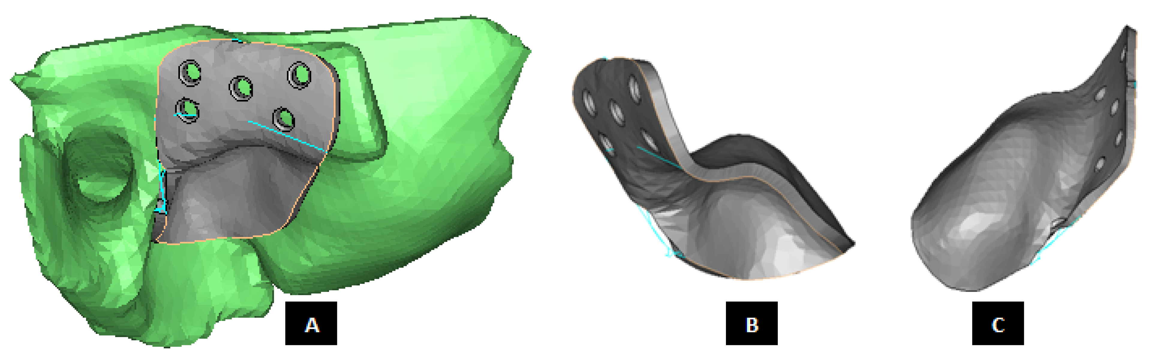
Figure 14.
Patient-fitted design of a fossa prosthesis. (A–C) Illustrate accurate fit of the device to the patient’s natural fossa and eminence. The rectangular slot (with curved anterior and posterior edges) in inferior surface of the implant is designed to provide sufficient rotation and opportunity for anterior-posterior and medio–lateral translation of the matching prosthetic condylar head. The articular grove is designed such that it would prevent dislocation of the prosthetic condylar head during functional movements of the jaw. Visuals in (D,E) show that the superior surface of the implant is designed to accurately match the shape of natural fossa. Sufficient thickness is maintained for the lateral portion of implant to pre-drill screw holes which can host locking screws for better fixation and stability.
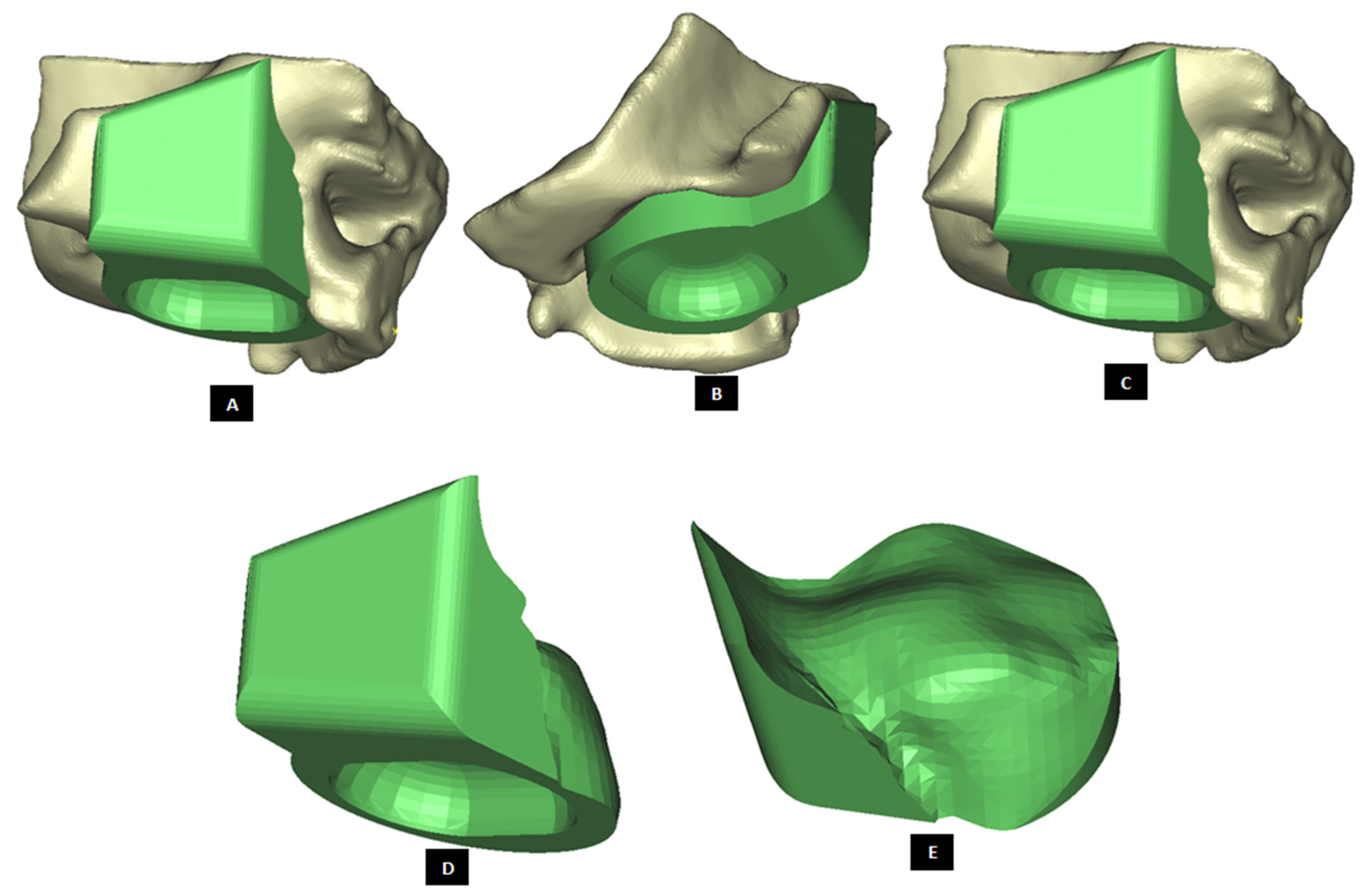
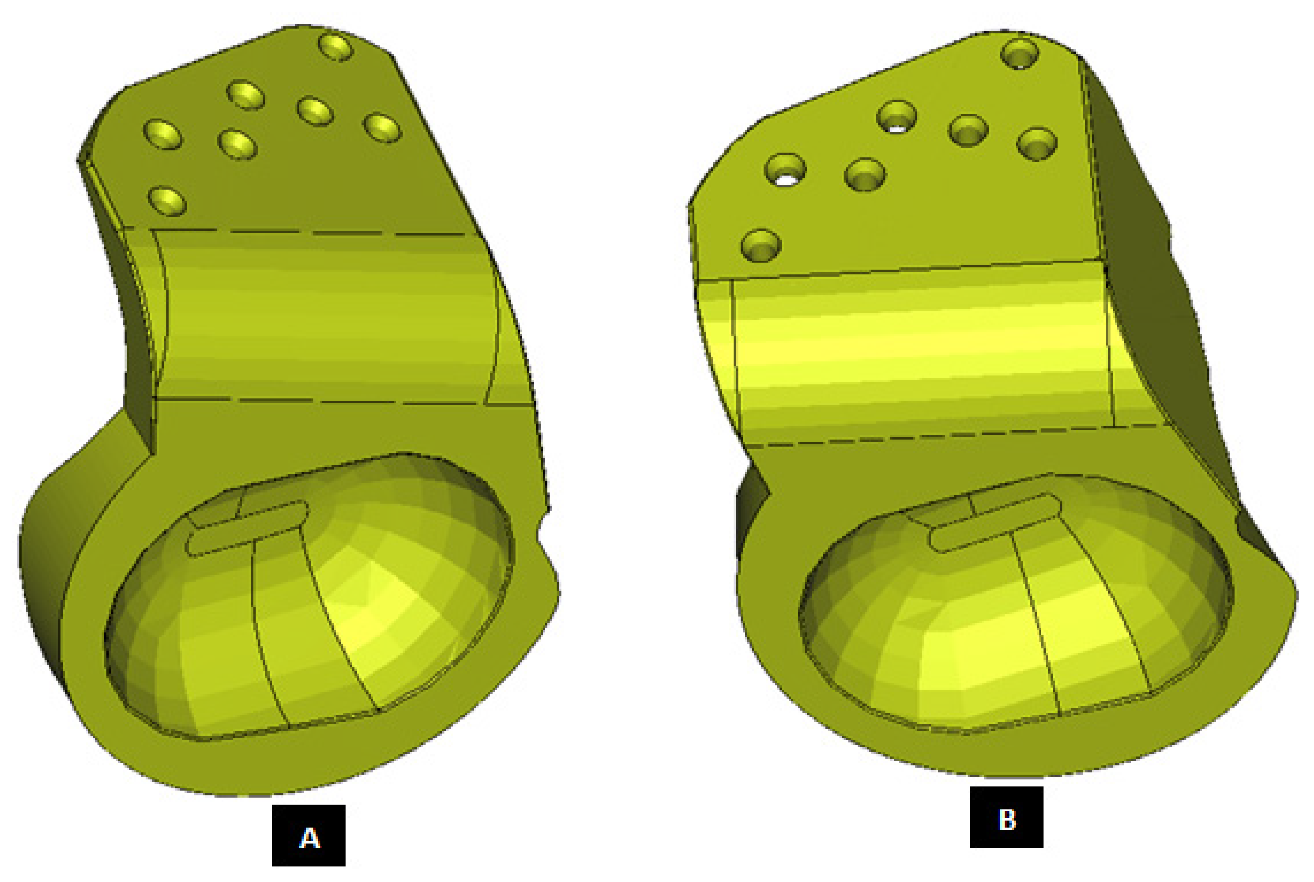
Figure 15.
Patient-specific design of fossa prosthesis. Inferior rectangular surface of the device has a circular grove for articulation with condylar head (A,B). Visuals illustrate customized size and shape of the device for accurate fit and fixation (C,D) to native anatomical structure. Superior edge of the lateral surface (which hosts screw holes) is custom cut to follow the curvature of native eminence and bone situation.
Figure 16.
Patient-fitted fossa implant with circular inferior surface which also has a circular grove for articulation with condylar head. Visuals in (A–D) demonstrate the customized size and shape of the implant.
Figure 16.
Patient-fitted fossa implant with circular inferior surface which also has a circular grove for articulation with condylar head. Visuals in (A–D) demonstrate the customized size and shape of the implant.
Figure 17.
Patient-specific design of fossa prosthesis (
A,
B). The device has a rectangular grove (with curved anterior and posterior edges) in its inferior surface for articulation with condylar head. The uniquely designed articulating surface/hole is slanted in anterior direction. This anterior slope of articulating surface is intended to provide opportunity for anterior translation of the condylar head during movements of mandible. This feature of our fossa prostheses provides an advantage over currently available total TMJ implants which, when implanted, only rotate but do not translate during functional movements of the patient’s jaw [
19].
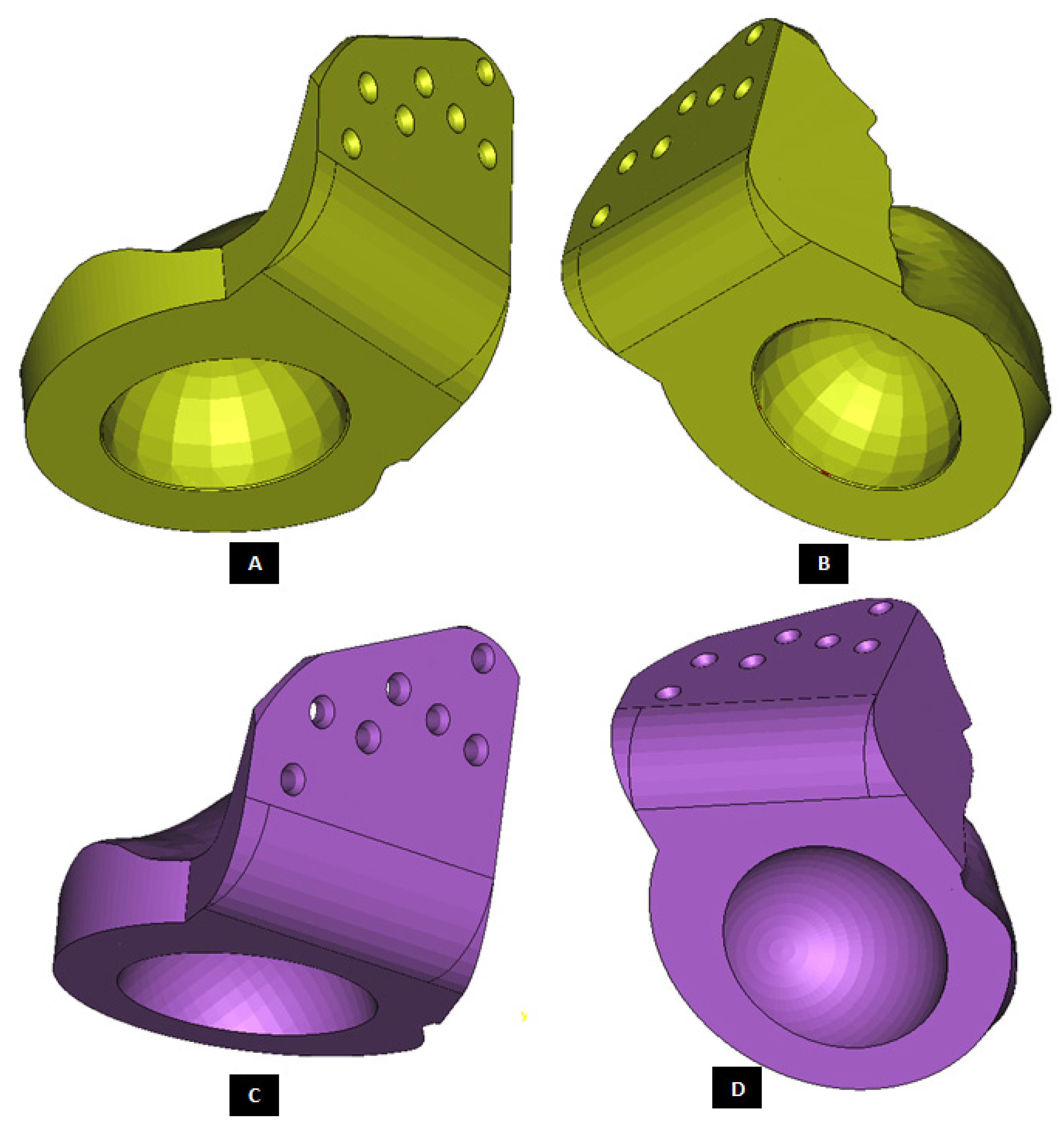
Figure 18.
Custom-designed fossa prosthesis with circular articular surface. The device shown in (A,B) has relatively smaller articulating circular hole compared to the one shown in (C,D). Additionally, articulating surface of the device shown in (C,D) is slanted anteriorly to augment anterior translation of condylar head during mastication.
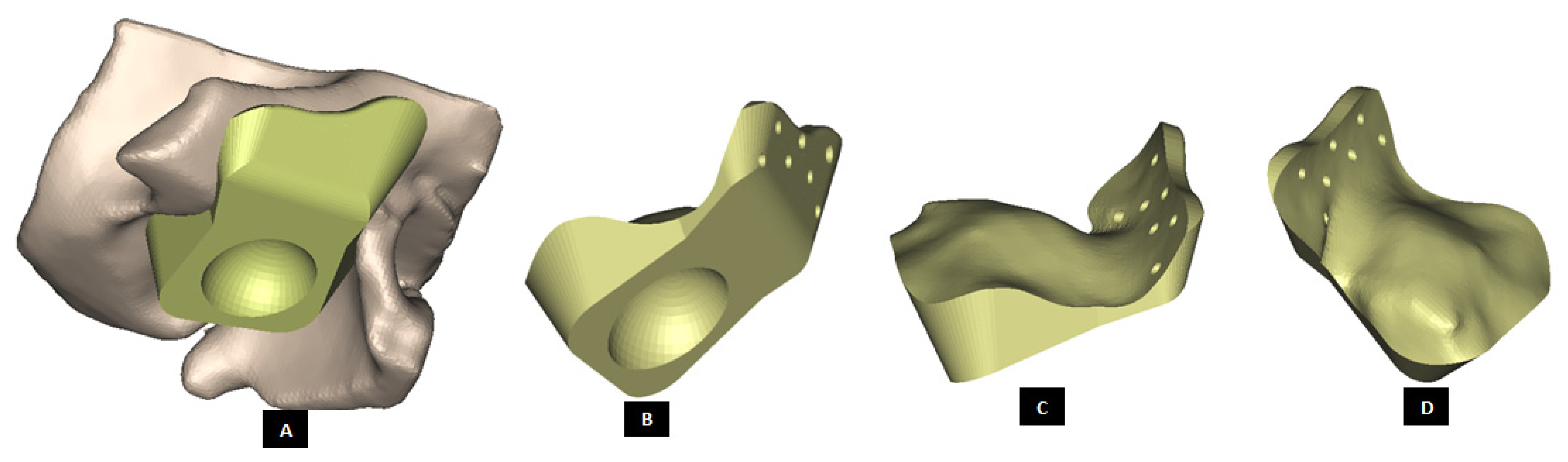
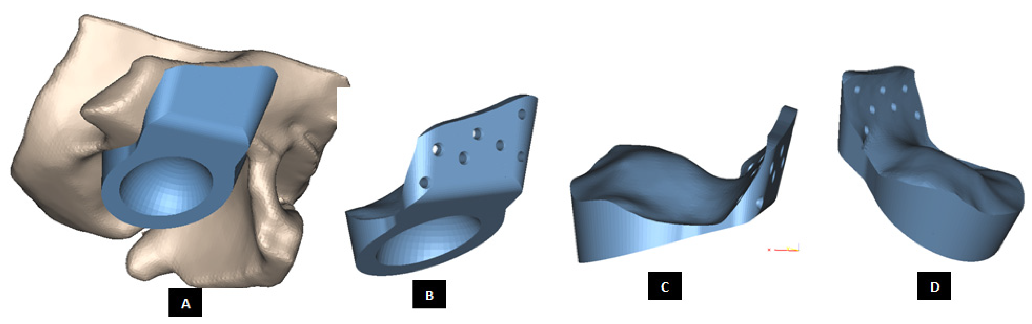
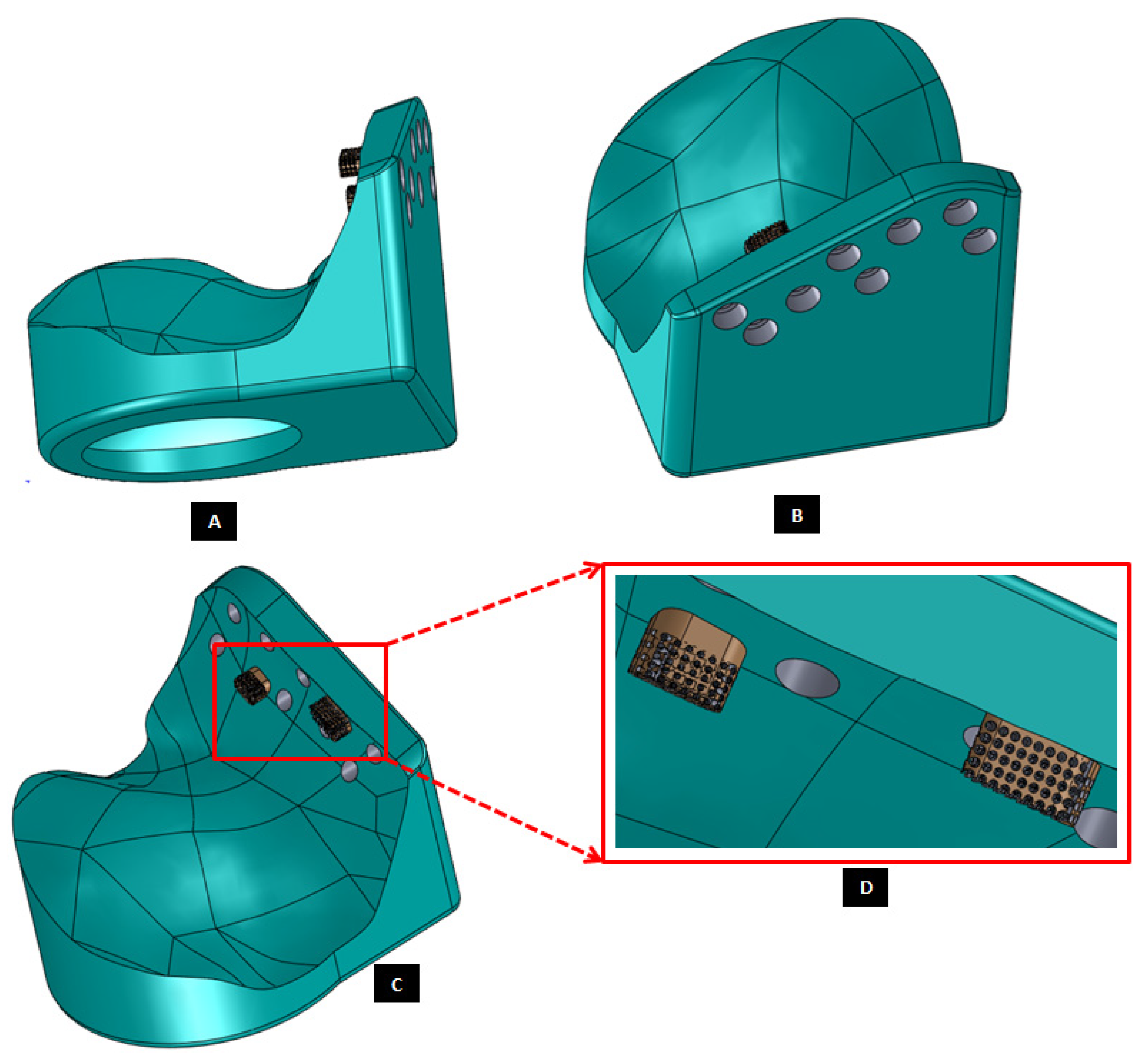
Figure 19.
Patient-specific design of a fossa implant with circular articular surface/hole in the inferior face of the device (A). The device has a novel feature; perforated medial notches (B) protruding into host bone at implantation. Each perforated notch is designed to fit into surgically created mating grove in the host bone, thereby maximizing device stability by allowing ingrowth of bone into the prosthesis after implantation (C,D). The notches also provide a mode for load transfer between the prosthesis and native bone, thereby reducing the amount of load and resultant stress acting on the fixation screws. The surgeons can be provided with custom-designed templates and cutting guides to accurately cut the slots in native bone to accommodate perforated notches.
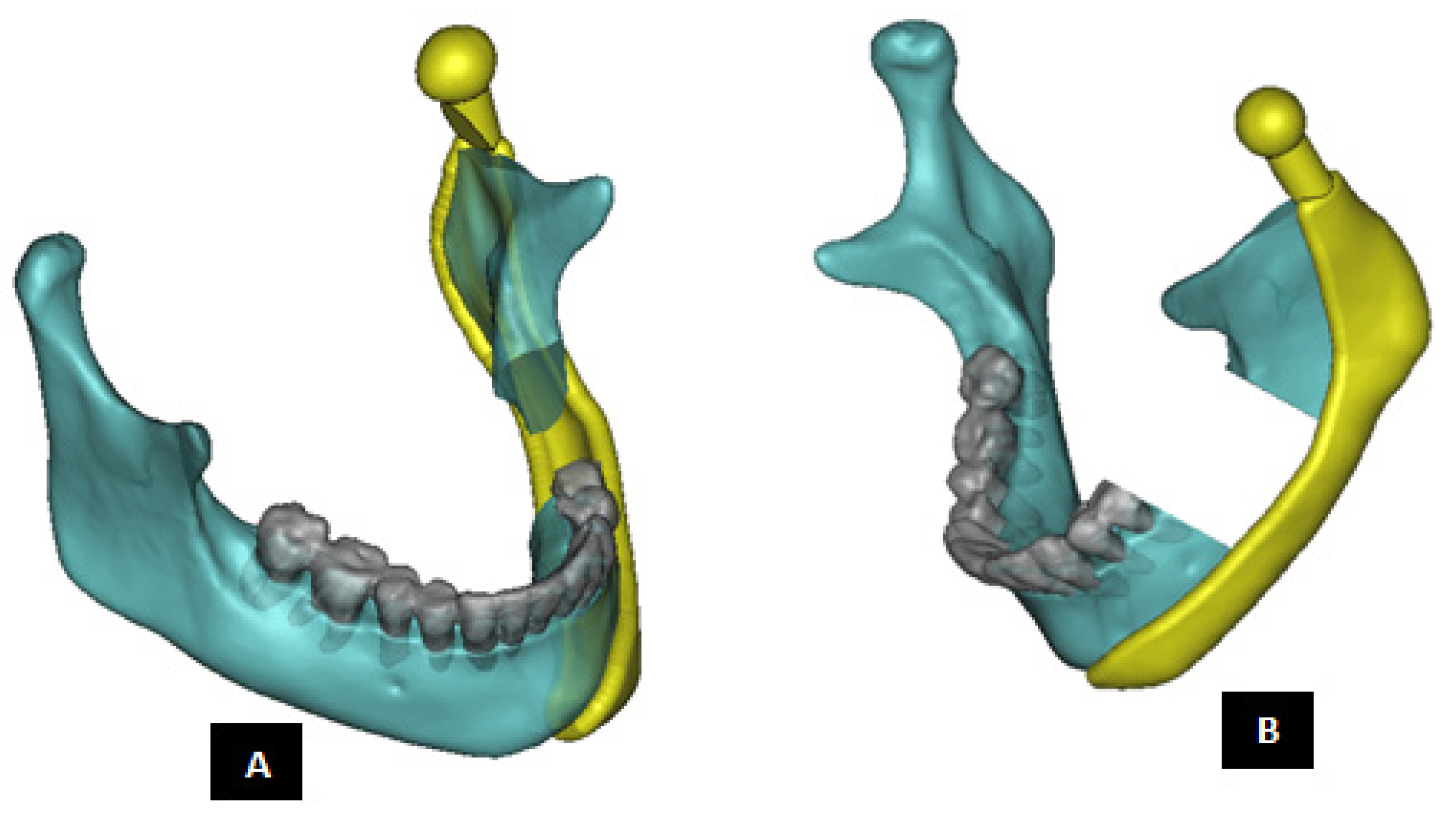
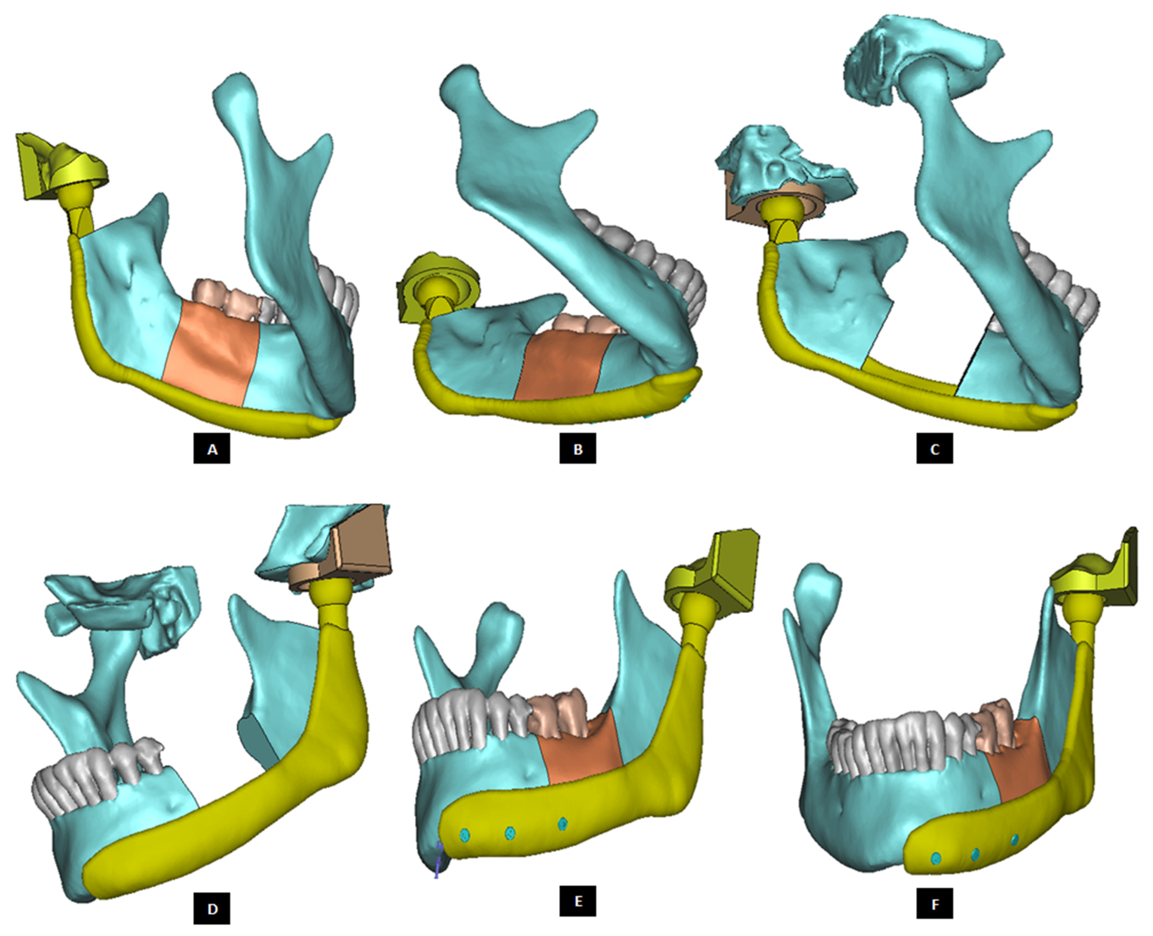
Figure 20.
Shape outline of the patient-specific total TMJ prosthesis. Ramal component of the prosthesis is extended anteriorly up to the chin (A–F) to support mandibular host bone and graft (with aesthetic dental implant) after removal of the imaginary tumor (shown in red) in the left mandibular body/molar region.
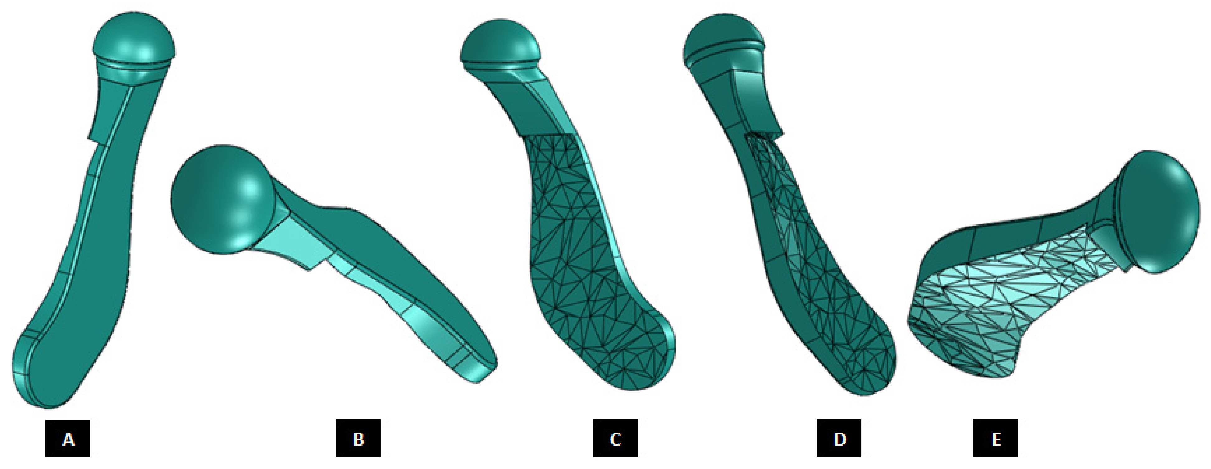
Figure 21.
Patient-specific total TMJ prostheses with different articulations and fixation (A–E).
Figure 21.
Patient-specific total TMJ prostheses with different articulations and fixation (A–E).
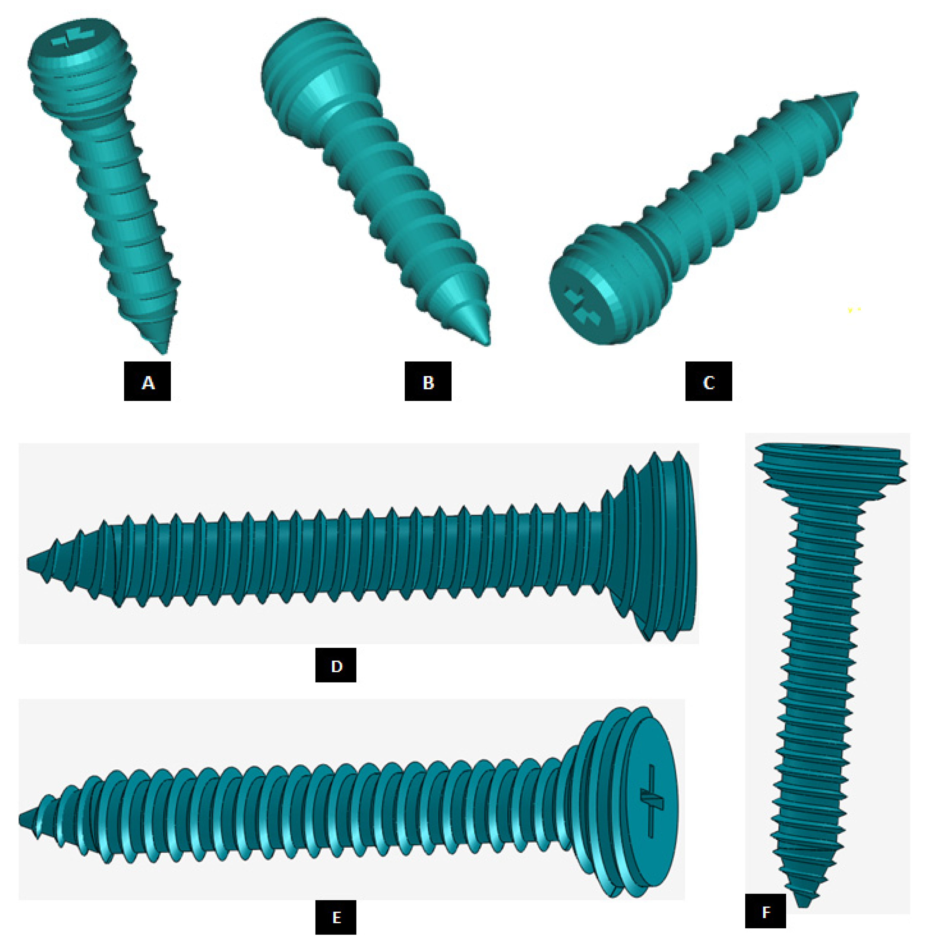
Figure 22.
Custom-designed screws with locking mechanism. The threads on the screw-head surface provide improved/optimal fixation by firmly engaging in the matching threads in the screws holes of either condylar/ramal or fossa component of the total TMJ prosthesis (A–F).
Figure 22.
Custom-designed screws with locking mechanism. The threads on the screw-head surface provide improved/optimal fixation by firmly engaging in the matching threads in the screws holes of either condylar/ramal or fossa component of the total TMJ prosthesis (A–F).
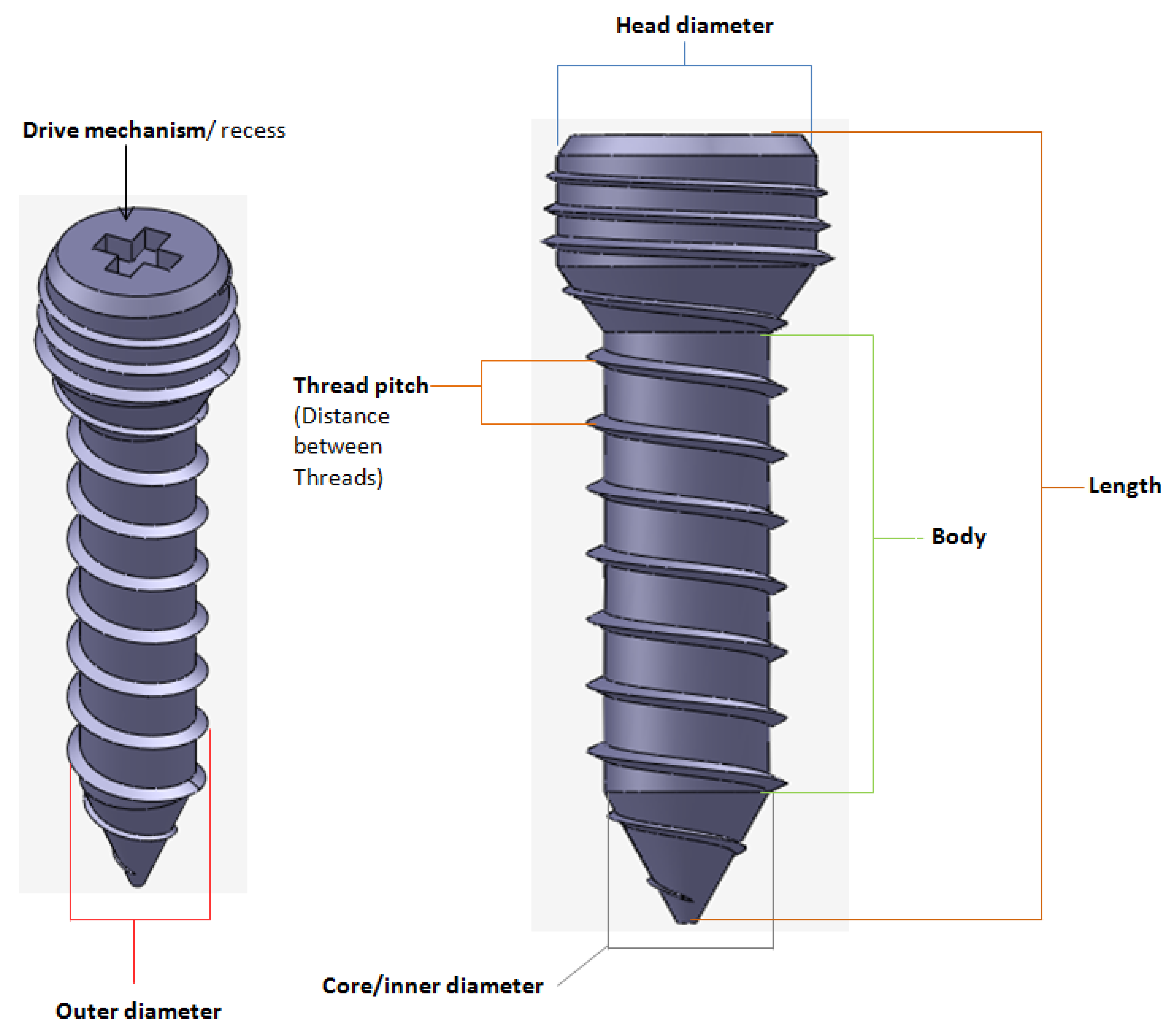
Figure 23.
A custom-designed locking screw for TMJ prosthesis. Visuals show different features of the screw. Total length of the screw depends on the size of prosthesis and native bone. The body/shaft of screw is designed long enough to utilize maximum amount of host bone (condyle/ramus or fossa eminence) but avoid protrusion of screws from medial surface of the bone. Length of the screw head varies depending on the thickness of condylar or fossa prosthesis in the particular screw-hole location. The outer diameter of screw is kept in the range of 1.5 mm–3.00 mm as this range is reported to be optimal for the screws of TMJ implants. The screw has varying pitch, with more threads per unit length of screw-head than the body/shaft.
Figure 24.
A patient-specific total TMJ prosthesis with medial notches in fossa and condylar components. (A) Shows anterior–lateral view of the ‘notched implants’ with screw holes. Fossa prosthesis has two medial notches to be fit into host bone (B,C). The articular surface of fossa implant has medio–lateral openings, and is designed to allow optimal anterior and medial translation along with rotation of the prosthetic condylar head along the medio–lateral axis.
Figure 25.
A patient-specific total TMJ prosthesis. (A,B) Show two views of the ‘simple’ total TMJ prosthesis along with left fossa bone and mandible after removal of left condyle. (C,D) Show two views of the total TMJ along with screws.
Figure 25.
A patient-specific total TMJ prosthesis. (A,B) Show two views of the ‘simple’ total TMJ prosthesis along with left fossa bone and mandible after removal of left condyle. (C,D) Show two views of the total TMJ along with screws.
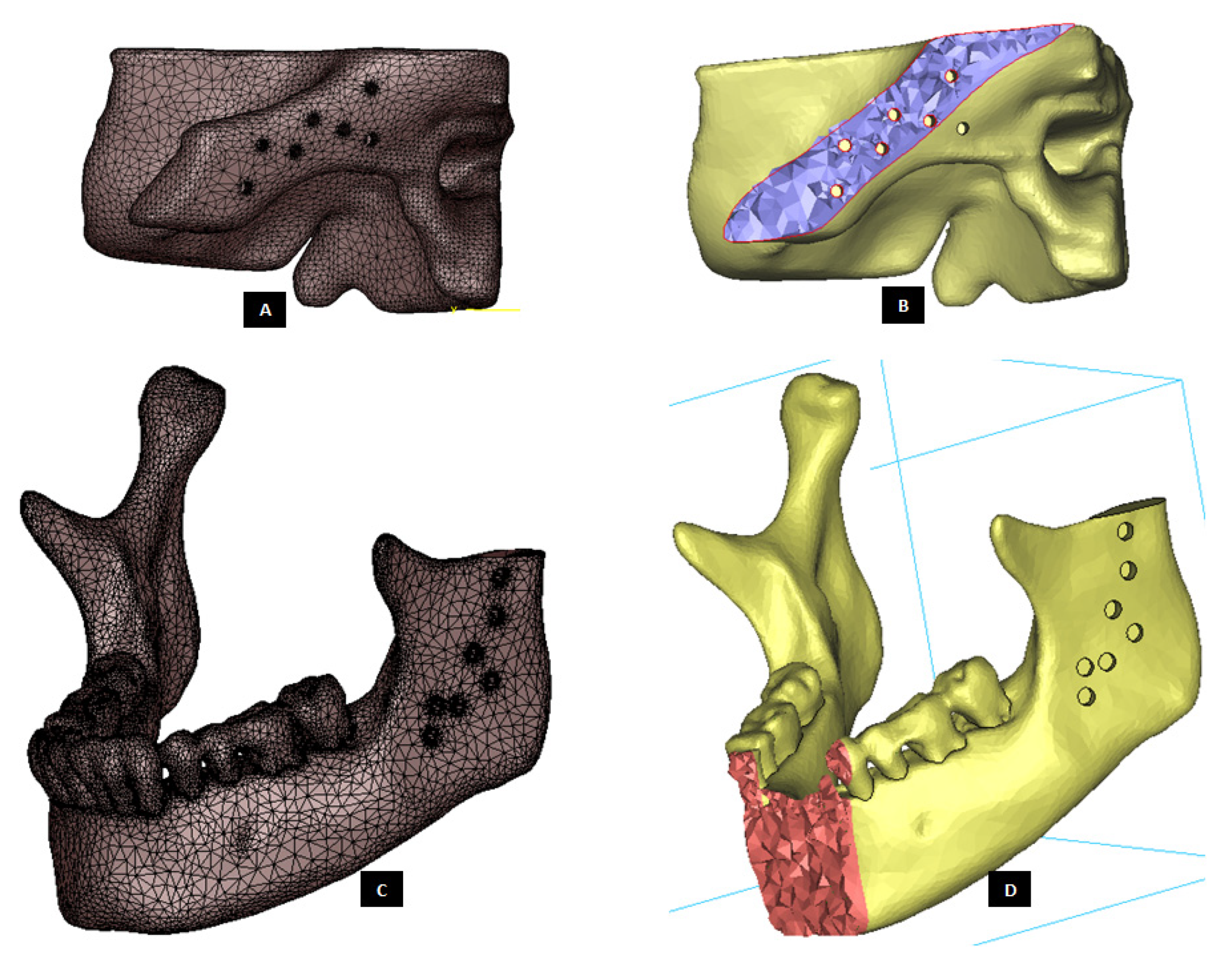
Figure 26.
Three-D finite element mesh of the host bone components prepared for total prosthetic replacement of the left TMJ. (A) Shows FE surface mesh of left fossa, and (B) shows a lateral cross-section of the 3D volume mesh of left fossa bone with screw holes. Similarly, (C,D) show surface mesh and anterior cross-section of volume mesh, respectively, of the mandible with screw holes and removal of damaged left condyle.
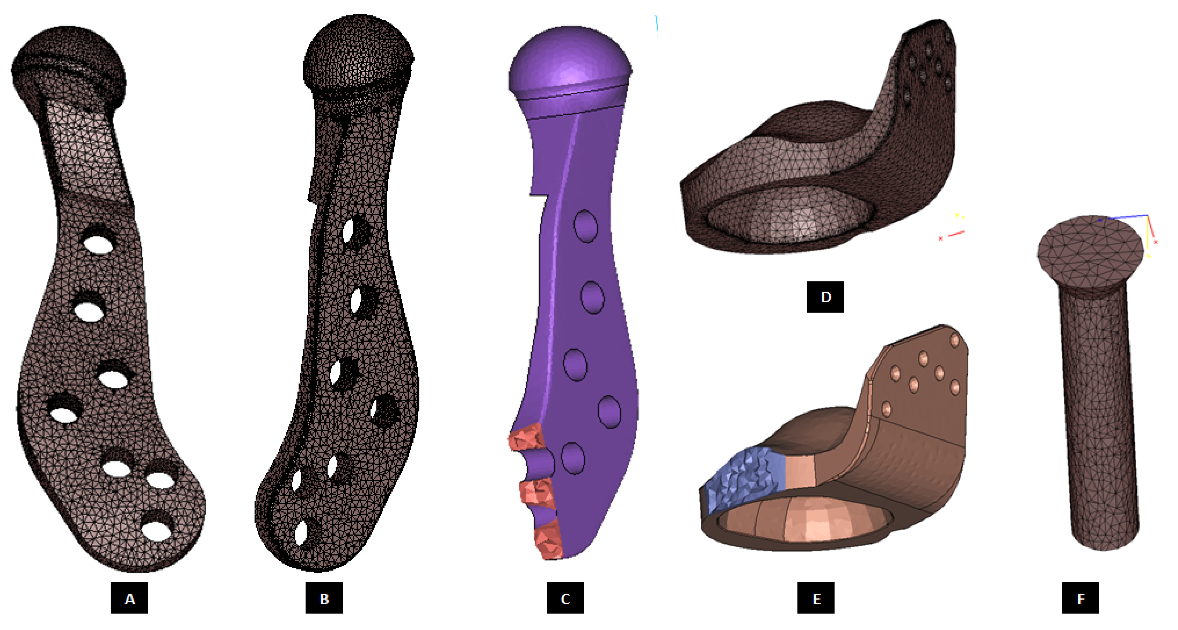
Figure 27.
Three-D finite element mesh of the components of patient-specific total TMJ prostheses. (A–C) Show FE mesh of the condylar/ramal component of the ‘simple’ TMJ implant (without notches). (D,E) Show FE mesh of the fossa component, and (F) demonstrates FE mesh of a screw for device fixation.
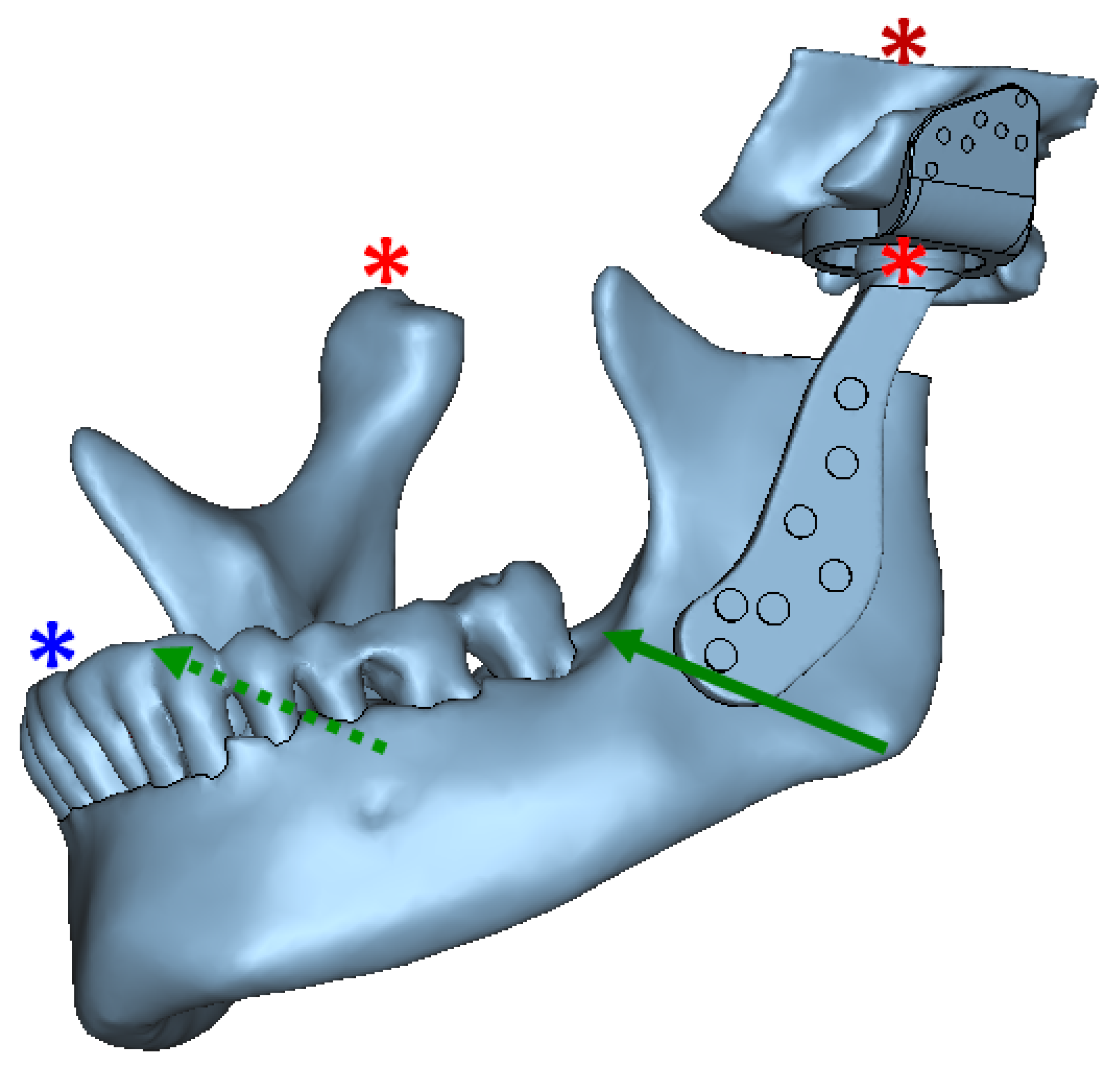
Figure 28.
Assembly of all parts of the FE model (including anatomic and prosthetic components), and schematic representation of model constraints and load application for FE simulation of total TMJ prostheses and anatomical components. Green arrows depict the location and direction of bite forces applied in the angulus region on both sides of the mandibular mesh. The asterisks indicate constrained nodes at condyle, fossa, and incisor teeth. Left prosthetic condylar head and right natural condylar head were constrained such that they could only rotate along the medio–lateral axis and translate in anterior-posterior direction. The nodes at incisor teeth were so constrained such that they could only rotate. The entire fossa host bone was constrained in all directions. The interface between prosthetic condylar head and articulating surface of prosthetic fossa was modeled as sliding contact. The prosthesis-to-bone, screw-to-prosthesis, and screw-to-bone interfaces were assumed to be bonded. The interfacial and boundary conditions were kept similar for normal and over–load configurations; and only magnitude of applied forces was changed across the two loading configurations.
![Materials 15 04342 g028]()
Figure 29.
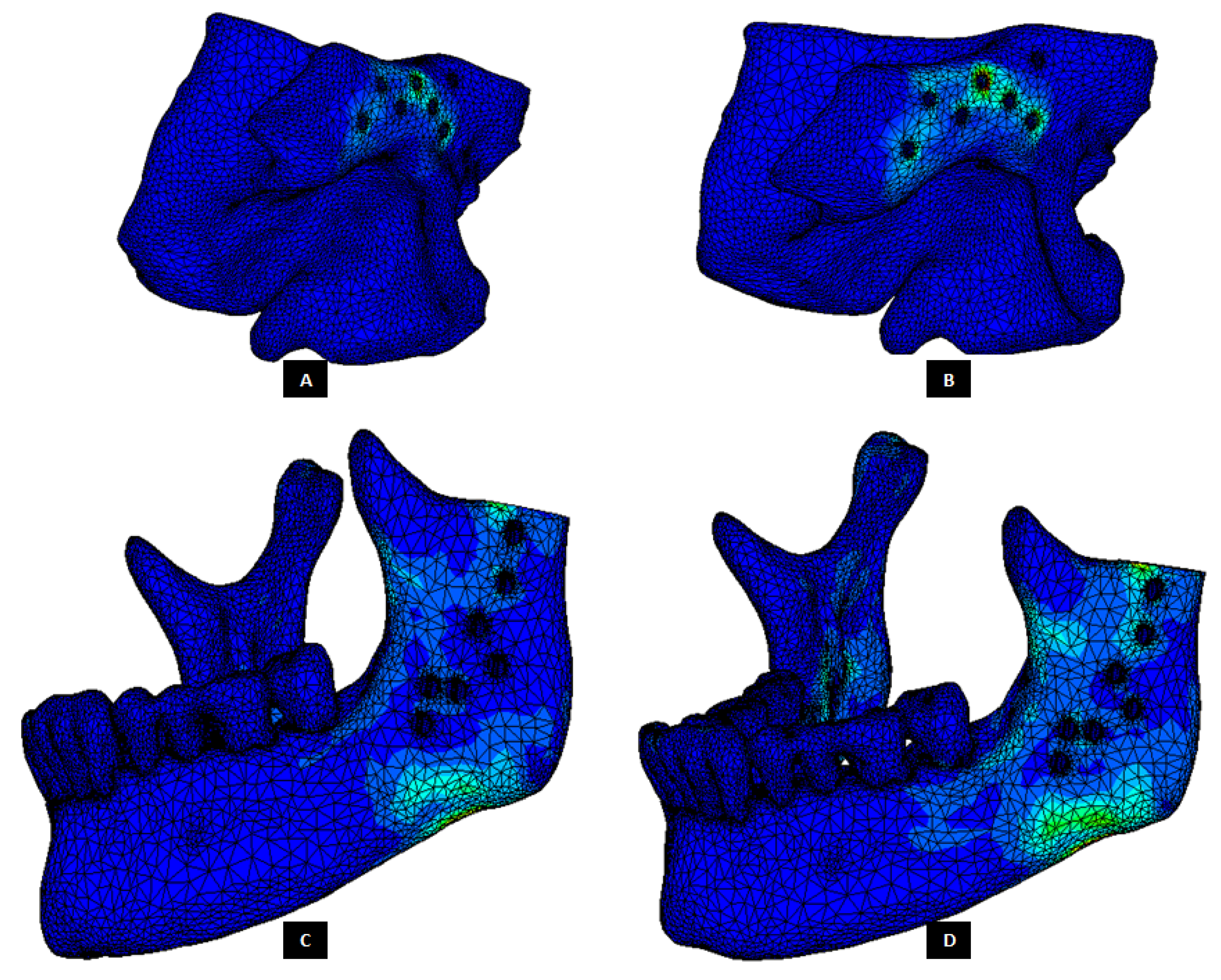
Stress distribution in the host bone components during FE simulations of the total TMJ replacement with custom designed simple TMJ prostheses. (A,B) Show von Mises stress in the fossa bone under normal and worst-case/over–load configurations, respectively. (C,D) Show von Mises stress in the mandibular bone under normal and worst-case/over–load configurations, respectively.
Figure 29.
Stress distribution in the host bone components during FE simulations of the total TMJ replacement with custom designed simple TMJ prostheses. (A,B) Show von Mises stress in the fossa bone under normal and worst-case/over–load configurations, respectively. (C,D) Show von Mises stress in the mandibular bone under normal and worst-case/over–load configurations, respectively.
Figure 30.
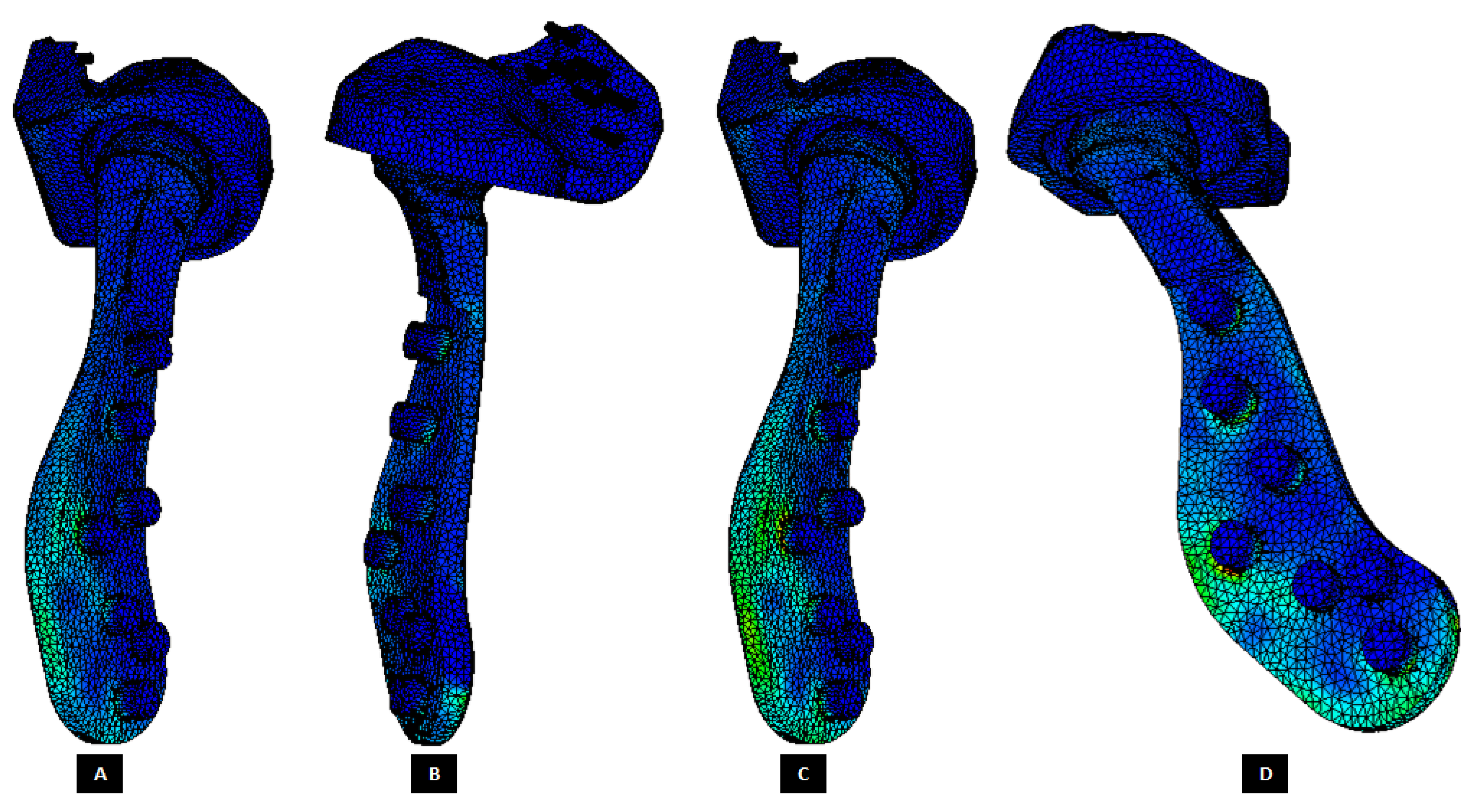
Peak von Mises stress in patient-specific ‘simple’ TMJ prosthesis (without notches) during FE simulations of two different loading scenarios. (A,B) Show von Mises total TMJ prosthesis under normal loading configuration. (C,D) Show von Mises stress profile in the prosthesis during FE simulation of worst-case/over-loading scenario.
Figure 30.
Peak von Mises stress in patient-specific ‘simple’ TMJ prosthesis (without notches) during FE simulations of two different loading scenarios. (A,B) Show von Mises total TMJ prosthesis under normal loading configuration. (C,D) Show von Mises stress profile in the prosthesis during FE simulation of worst-case/over-loading scenario.
Figure 31.
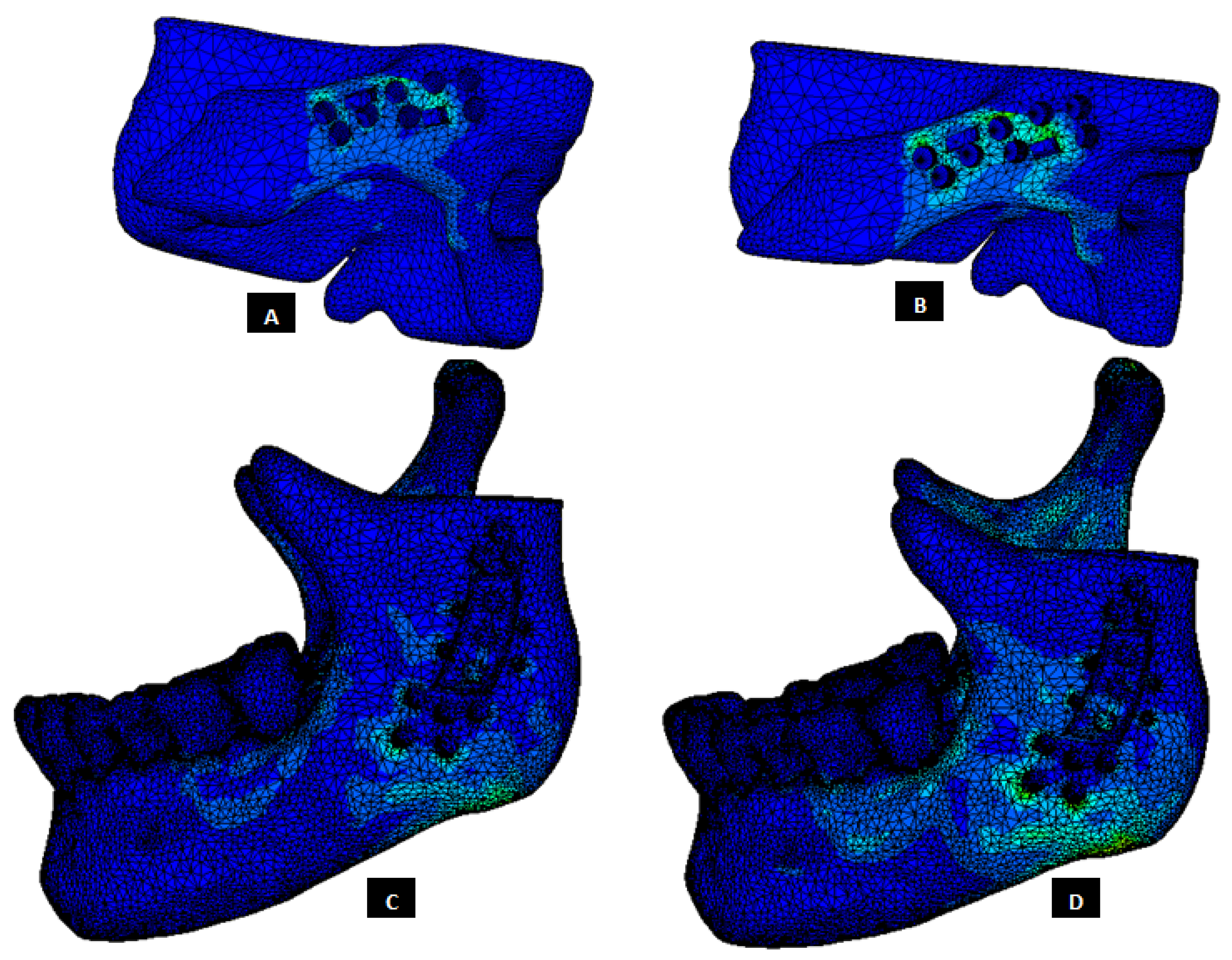
Stress distribution in the host bone components during FE simulations of the total TMJ replacement with custom designed TMJ prostheses with medial notches. (A,B) Show von Mises stress in the fossa bone under normal and worst-case/over-load configurations, respectively. (C,D) Show von Mises stress in the mandibular bone under normal and worst-case/over-load configurations, respectively.
Figure 31.
Stress distribution in the host bone components during FE simulations of the total TMJ replacement with custom designed TMJ prostheses with medial notches. (A,B) Show von Mises stress in the fossa bone under normal and worst-case/over-load configurations, respectively. (C,D) Show von Mises stress in the mandibular bone under normal and worst-case/over-load configurations, respectively.
Figure 32.
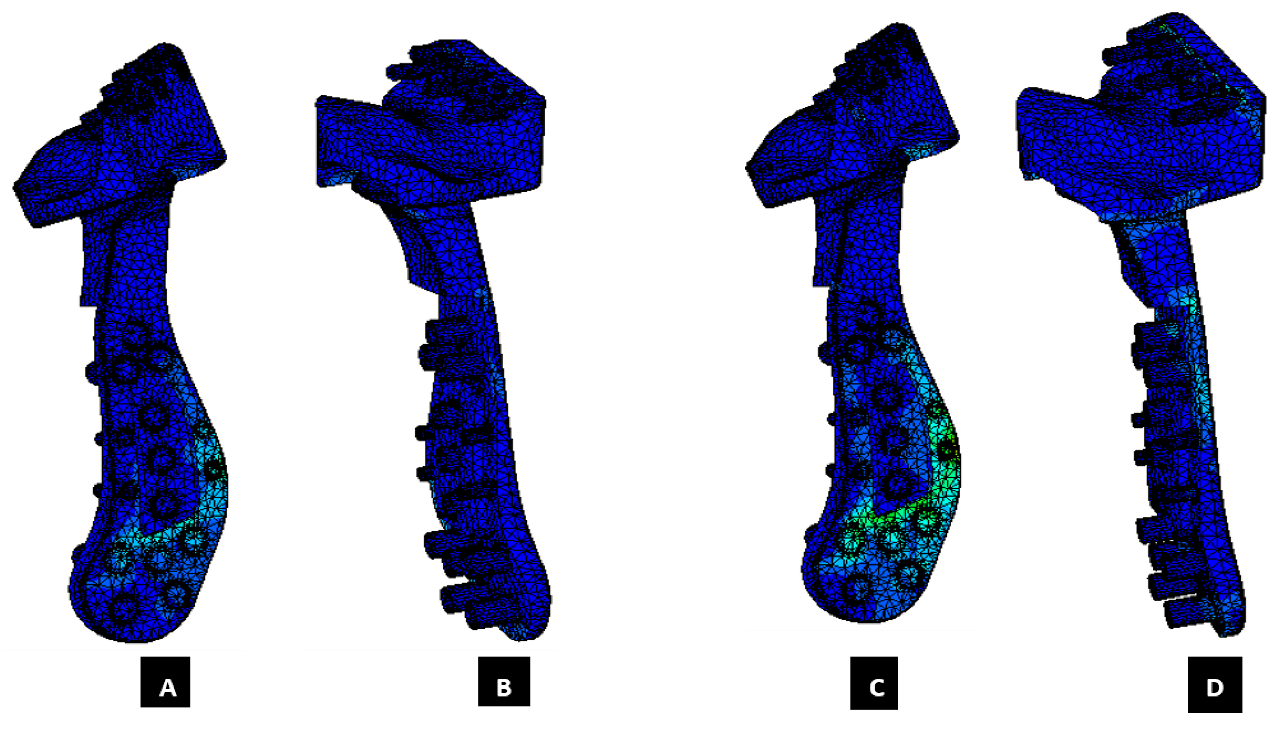
Peak von Mises stress in patient-specific ‘notched’ TMJ prosthesis (with medial notches) during FE simulations of two different loading scenarios. (A,B) Show von Mises total TMJ prosthesis under normal loading configuration. (C,D) Show von Mises stress profile in the prosthesis during FE simulation of worst-case/over-loading scenario.
Figure 32.
Peak von Mises stress in patient-specific ‘notched’ TMJ prosthesis (with medial notches) during FE simulations of two different loading scenarios. (A,B) Show von Mises total TMJ prosthesis under normal loading configuration. (C,D) Show von Mises stress profile in the prosthesis during FE simulation of worst-case/over-loading scenario.
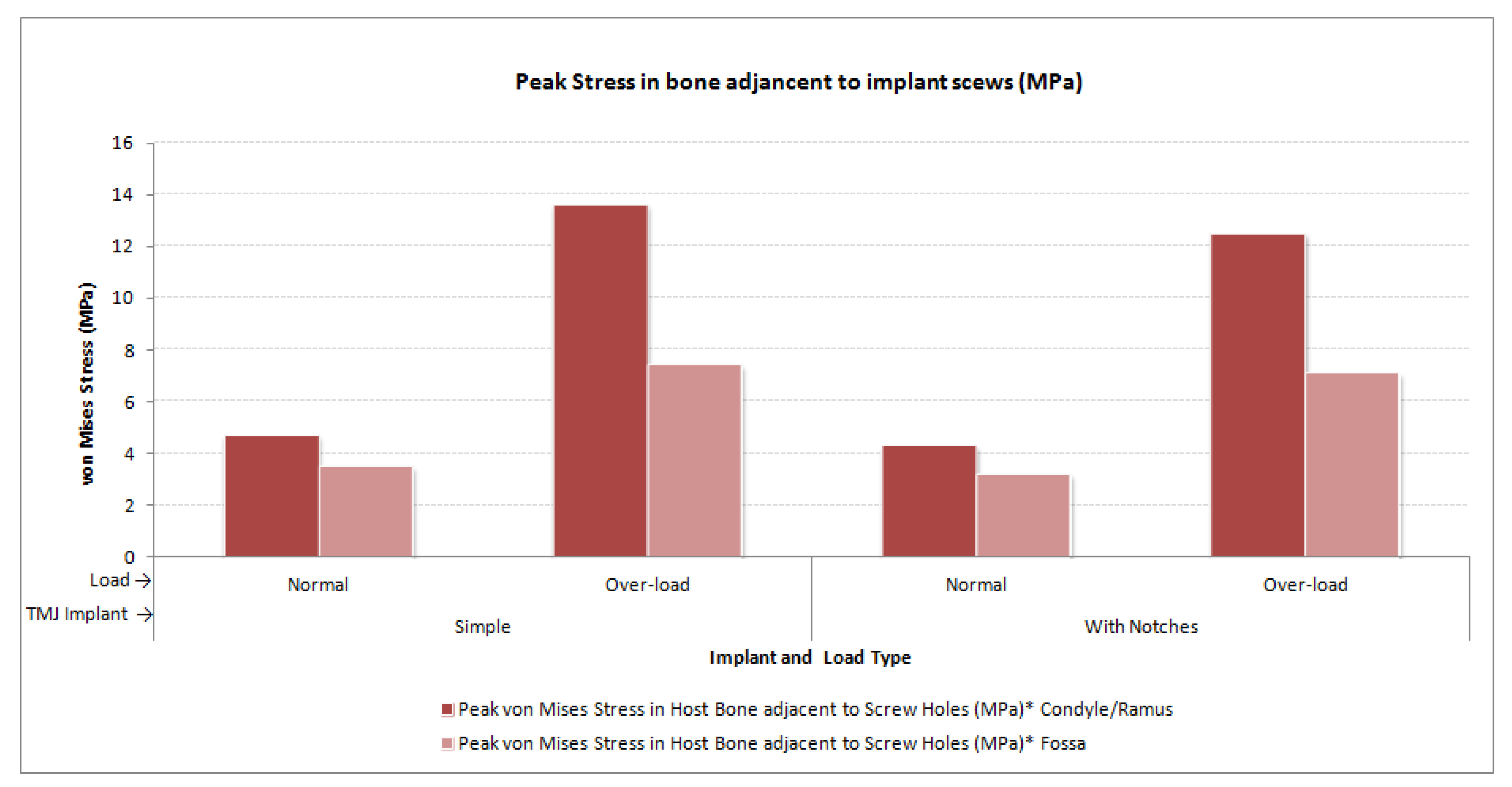
Figure 33.
Peak von Mises stress in the mandibular and fossa bone adjacent to fixation screws of total TMJ prostheses during FE simulations under normal and worst-case/over-load configurations.
Figure 33.
Peak von Mises stress in the mandibular and fossa bone adjacent to fixation screws of total TMJ prostheses during FE simulations under normal and worst-case/over-load configurations.
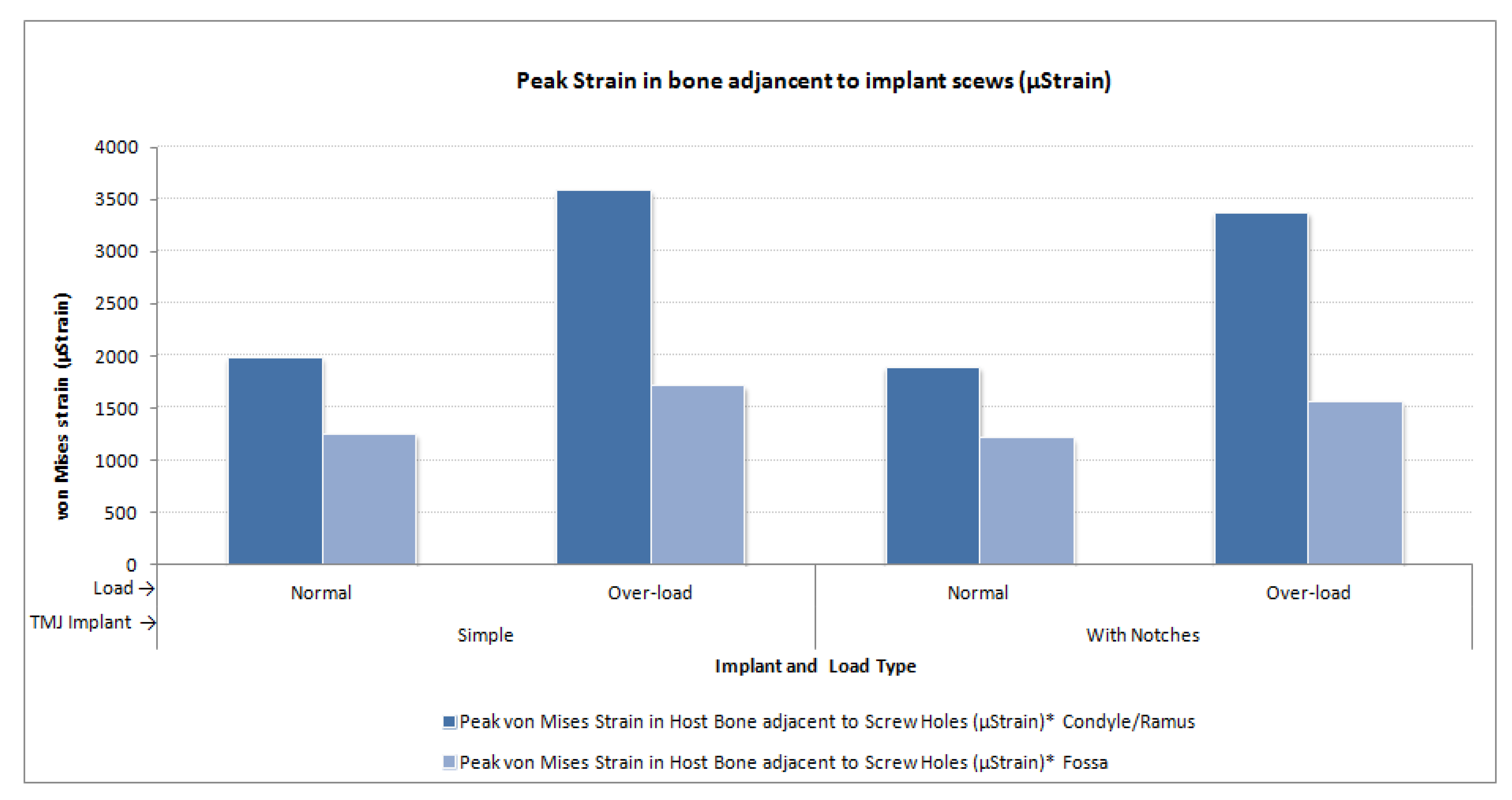
Figure 34.
Peak micro-strain in the mandibular and fossa bone adjacent to fixation screws of total TMJ prostheses during FE simulations under normal and worst-case/over-load configurations.
Figure 34.
Peak micro-strain in the mandibular and fossa bone adjacent to fixation screws of total TMJ prostheses during FE simulations under normal and worst-case/over-load configurations.
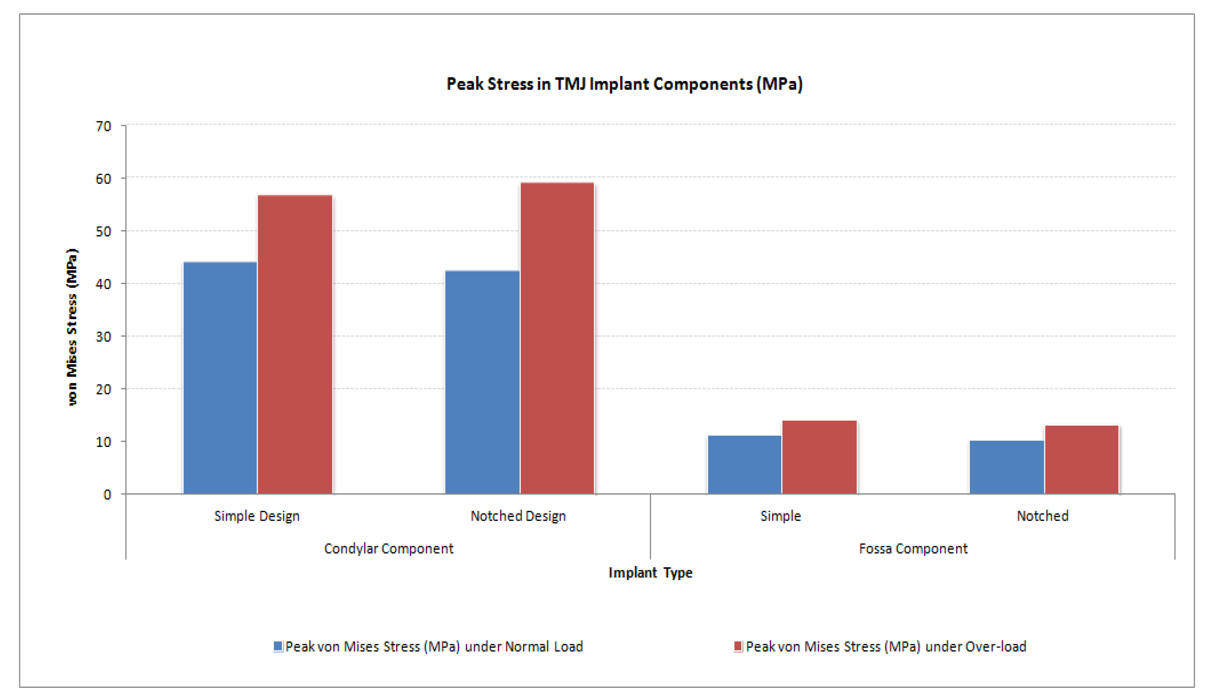
Figure 35.
Peak von Mises stress in condylar/ramus and fossa components of patient-specific total TMJ prostheses during FE simulations under normal and worst-case/over-load configurations.
Figure 35.
Peak von Mises stress in condylar/ramus and fossa components of patient-specific total TMJ prostheses during FE simulations under normal and worst-case/over-load configurations.
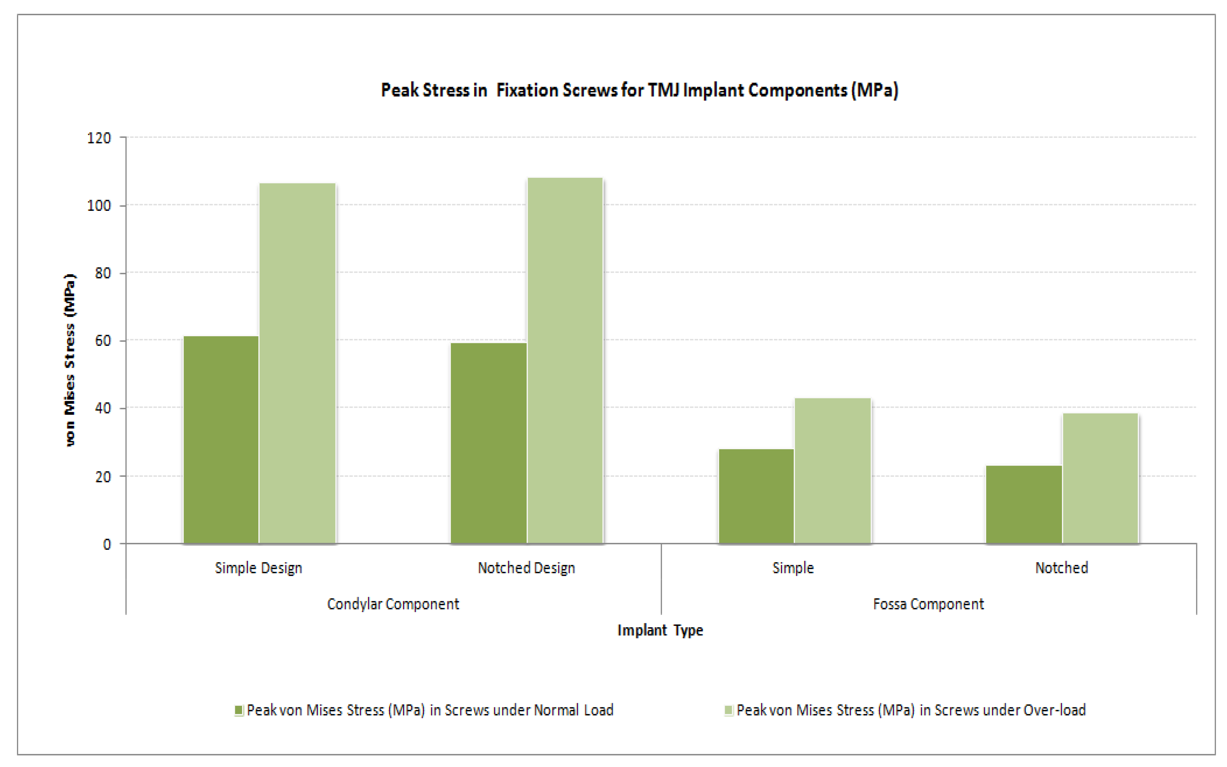
Figure 36.
Peak von Mises stress in the fixation screws for condylar/ramus and fossa components of patient-specific total TMJ prostheses during FE simulations under normal and worst-case/over-load configurations.
Figure 36.
Peak von Mises stress in the fixation screws for condylar/ramus and fossa components of patient-specific total TMJ prostheses during FE simulations under normal and worst-case/over-load configurations.
Table 1.
Indications for the alloplastic reconstruction of the temporomandibular joint (TMJ).
Table 1.
Indications for the alloplastic reconstruction of the temporomandibular joint (TMJ).
| Sr. No. | Indications for Alloplastic TMJ Reconstruction |
|---|
| 1. | Ankylosis or reankylosis [1,3,4], degeneration, or resorption [3,4] of joints with severe anatomic abnormalities. |
| 2. | Failed autogenous grafts in multiply operated patients [1,3,4]. |
| 3. | Destruction of autogenous graft tissue by pathology [1,3,4]. |
| 4. | Failed Proplast–Teflon that results in severe anatomic joint mutilation [1,3,4]. |
| 5. | Failed Vitek–Kent total or partial joint reconstruction [1]. |
| 6. | Severe inflammatory joint disease, such as rheumatoid arthritis which results in anatomic mutilation of the joint components and functional disability [1,3,4]. |
Table 2.
Criteria for the successful alloplastic total reconstruction of the TMJ.
Table 2.
Criteria for the successful alloplastic total reconstruction of the TMJ.
| Sr. No. | Requirements/Criteria for Success of Alloplastic Total Joint Replacement Devices |
|---|
| 1. | The materials from which the devices are made must be biocompatible [1,2,15,16]. |
| 2. | The devices must be designed with sufficient mechanical strength to withstand the loads delivered over the full range of function of the joint [1,2,15,16]. |
| 3. | The devices must be stable in-situ [1,2,15,16]. |
| 4. | The surgery to implant the prosthesis must be performed for the proper indications, and it must be performed aseptically [1,2,16]. |
| 5. | The prostheses should imitate the condylar translation during mouth opening, and without restricting movements of non-replaced TMJ [15]. |
| 6. | The prostheses should be fitted correctly to the mandible and the skull [15]. |
| 7. | Expected lifetime of more than 20 years [15]. |
| 8. | Low wear rate; and wear particles must be tolerated by the body [15]. |
| 9. | Simple and reliable implantation procedures [15]. |


