
A Kinetic Model for the Modification of Al2O3 Inclusions during Calcium Treatment in High-Carbon Hard Wire Steel

Abstract
:1. Introduction
2. Experiment
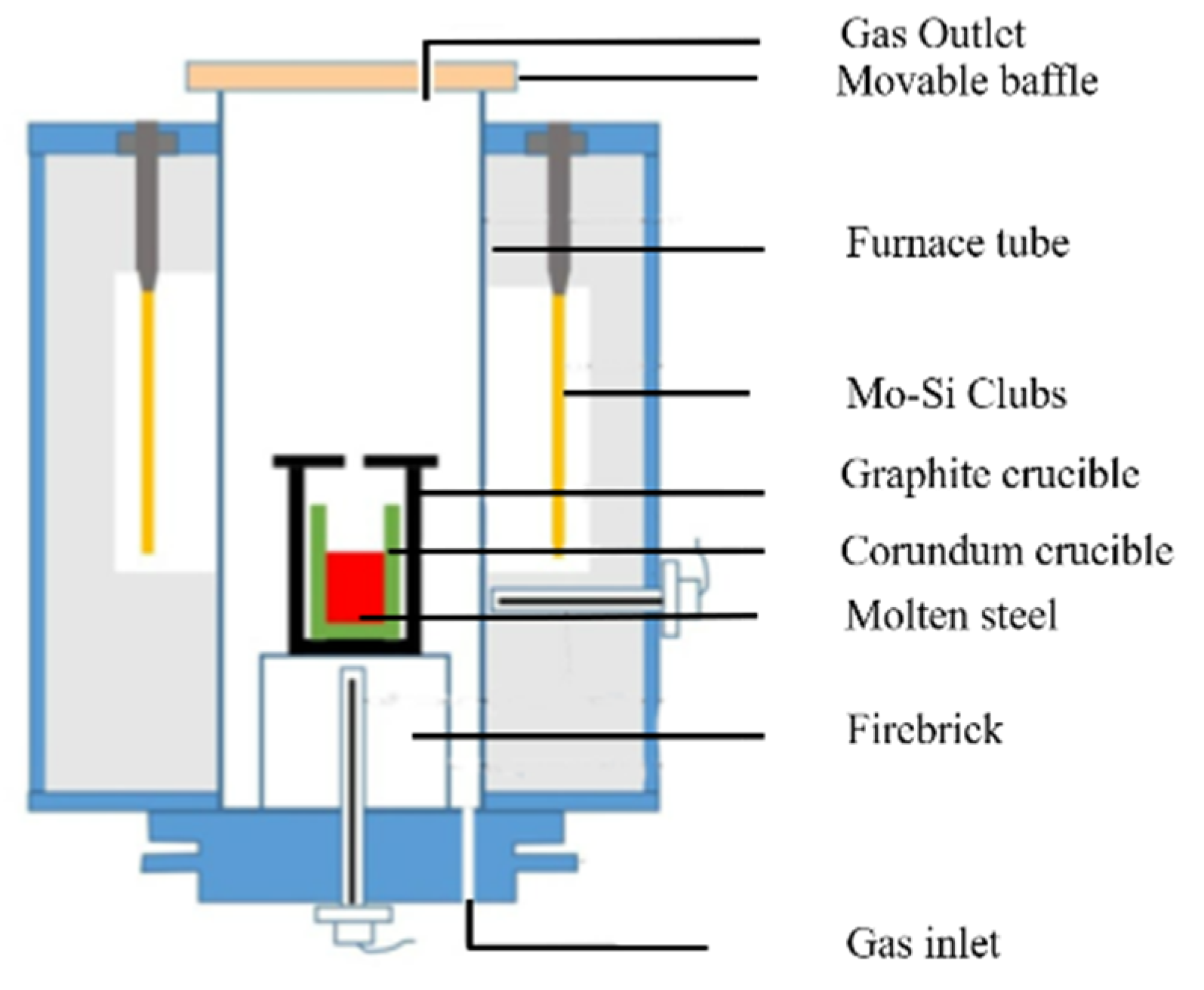
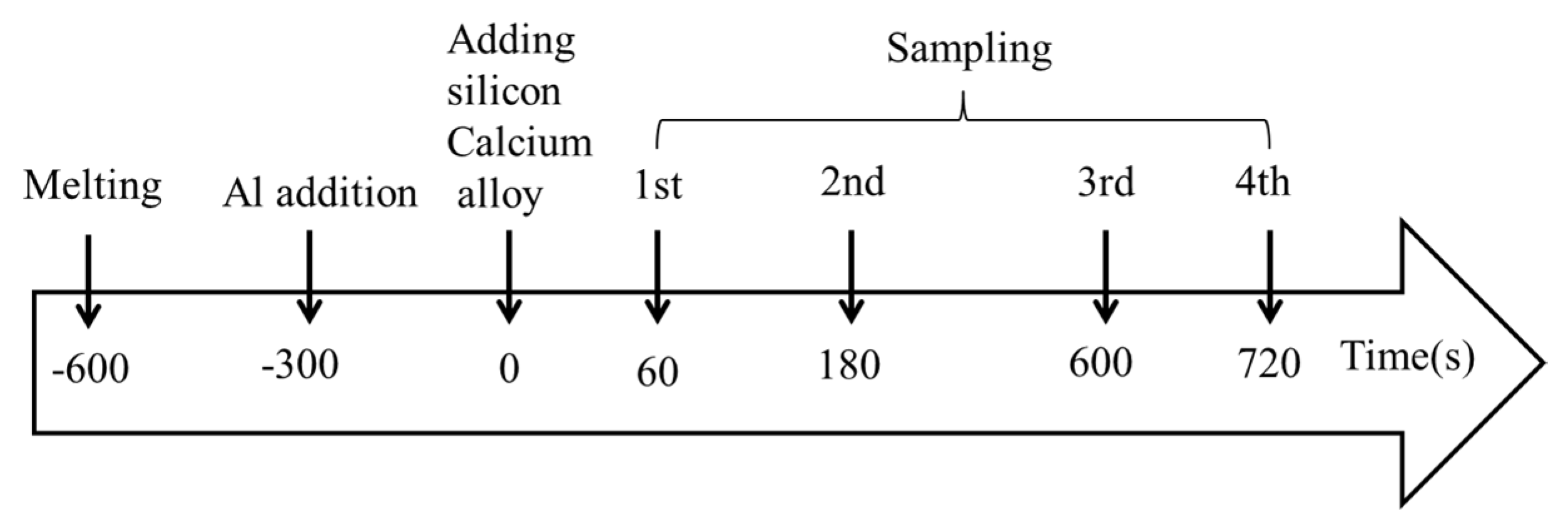
2.1. Experimental Procedure
2.2. Composition Analysis for Steels and Inclusions
3. Results
3.1. Chemical Compositions of Steels
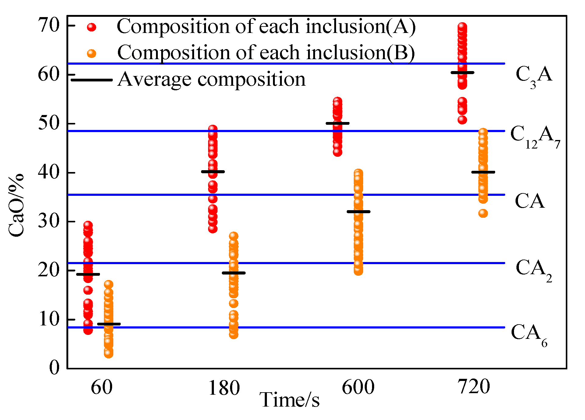
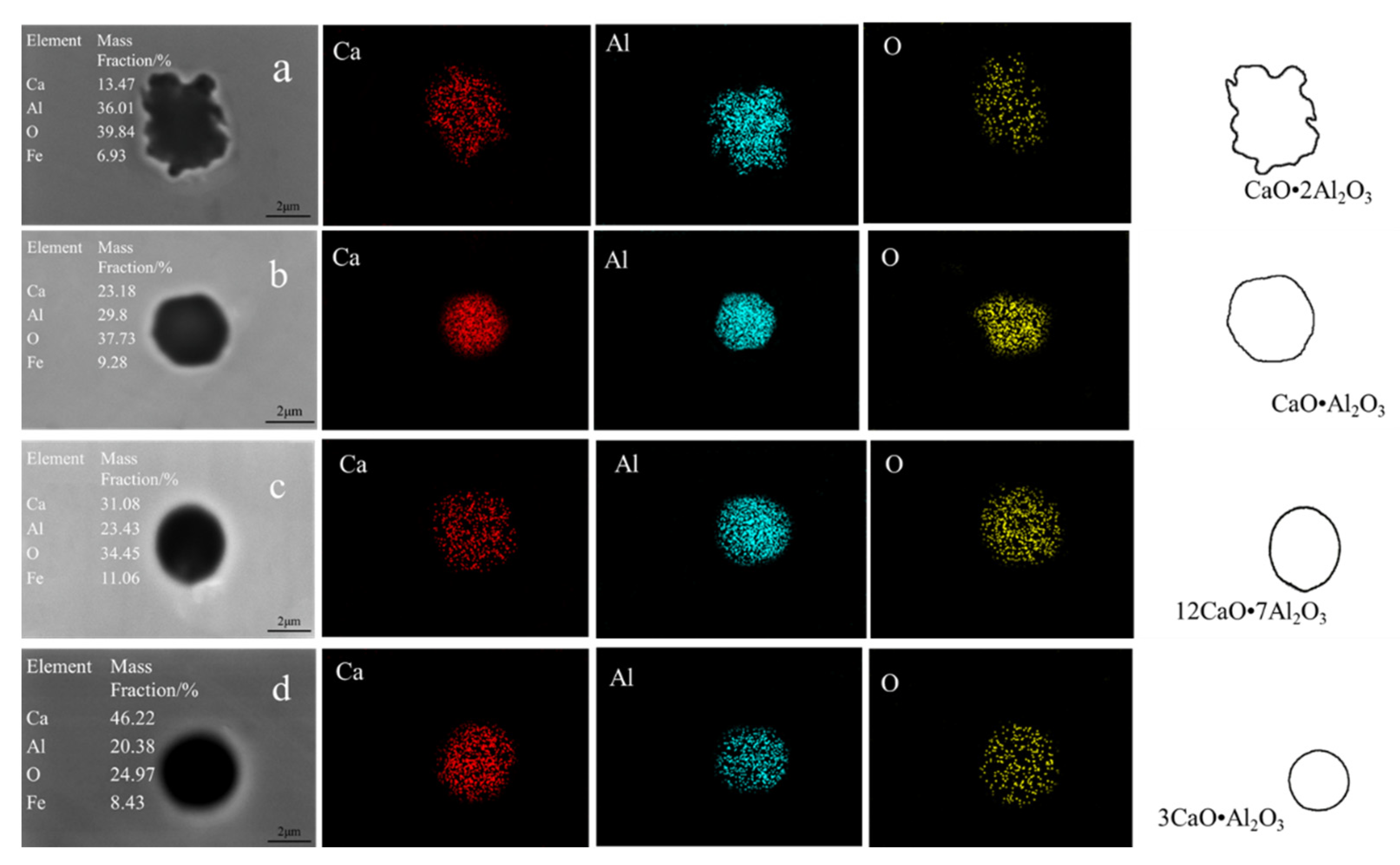
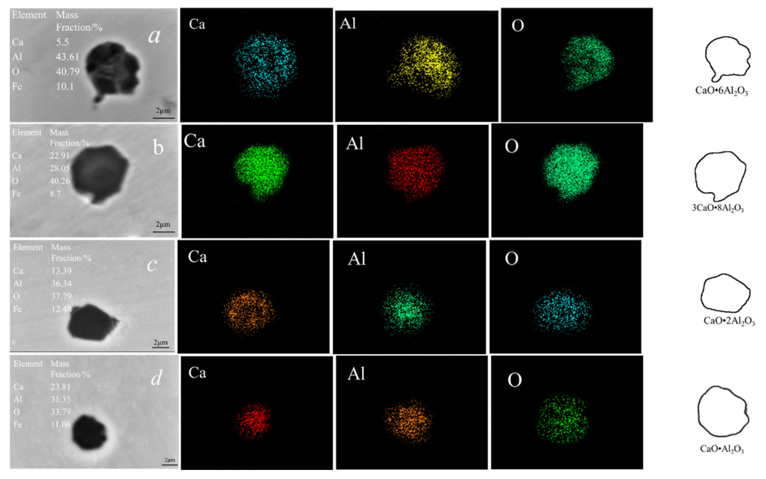
3.2. Compositions and Morphologies of Inclusions
4. Discussion
4.1. Dynamic Model
- All inclusions in molten steel are spherical before and during the calcium treatment process;
- The temperature of molten steel is very high at 1600 °C, so the interfacial reaction is assumed to be in equilibrium;
- To simplify the discussion of the model, the concentrations of calcium, aluminum, and oxygen in molten steel are assumed to be constant;
- The diffusion of all substances in the liquid calcium aluminate layer is steady, which is in accordance with Fick’s first law.
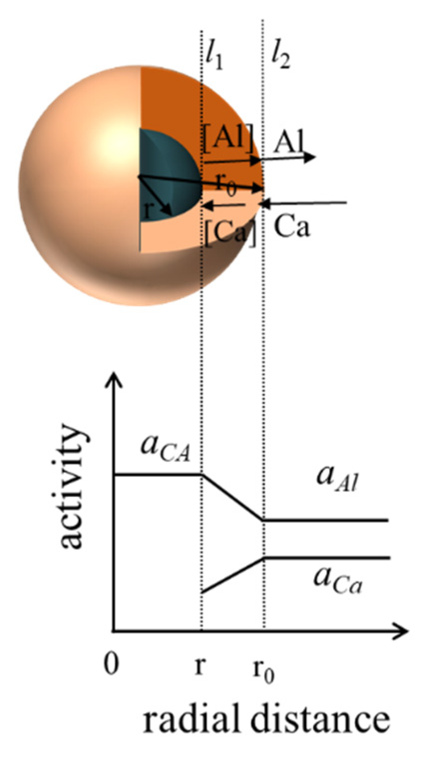
- Ca in molten steel diffuses to the C12A7 layer–molten steel interface, for which the reaction formula is:
- [Ca] passes through the C12A7 liquid phase, diffuses to the CA layer, and reacts with it:
- At this time, the generated [Al] diffuses outward through the C12A7 liquid phase layer and enters into the molten steel.
4.2. Model and Parameter Determination
4.3. Determination of Restrictive Links
4.4. Effects of Solute Element Content in Molten Steel on Modification Time
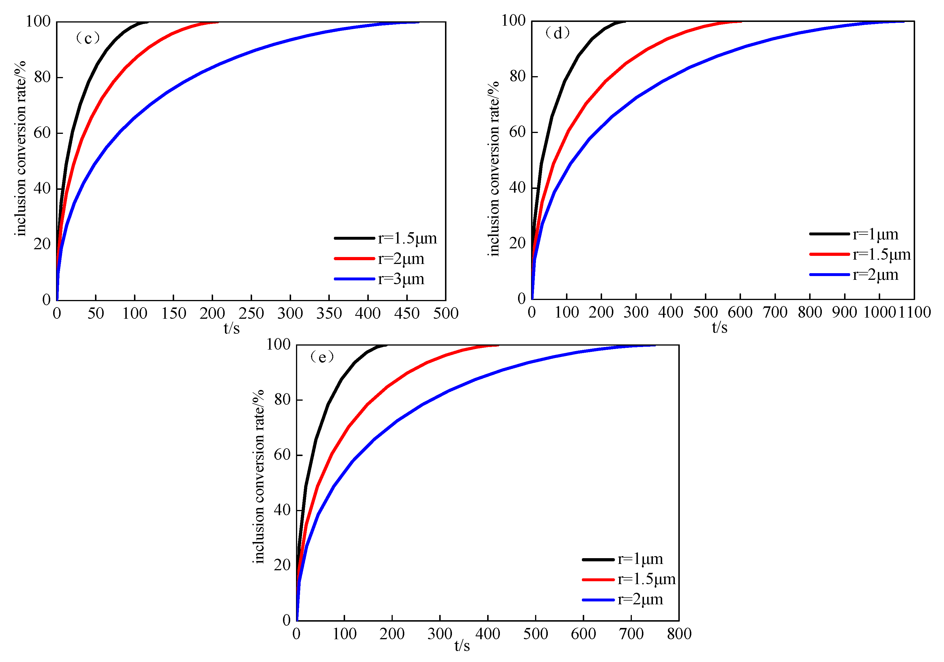
4.5. Influence of Inclusion Conversion Rate in Molten Steel on Modification Time
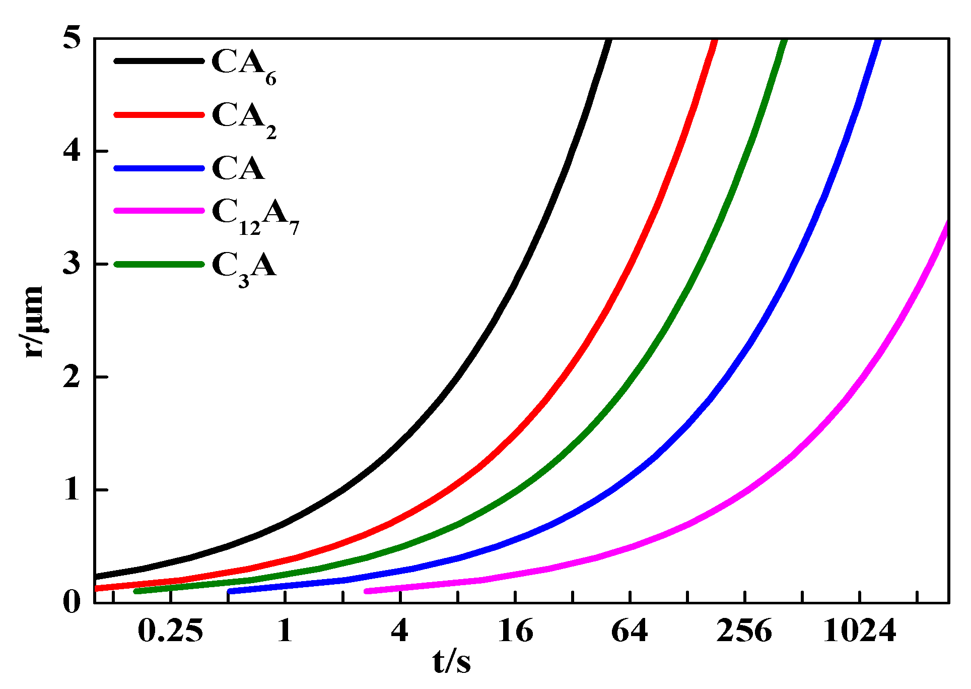
4.6. Relationship between Inclusion Radius and Modification Time
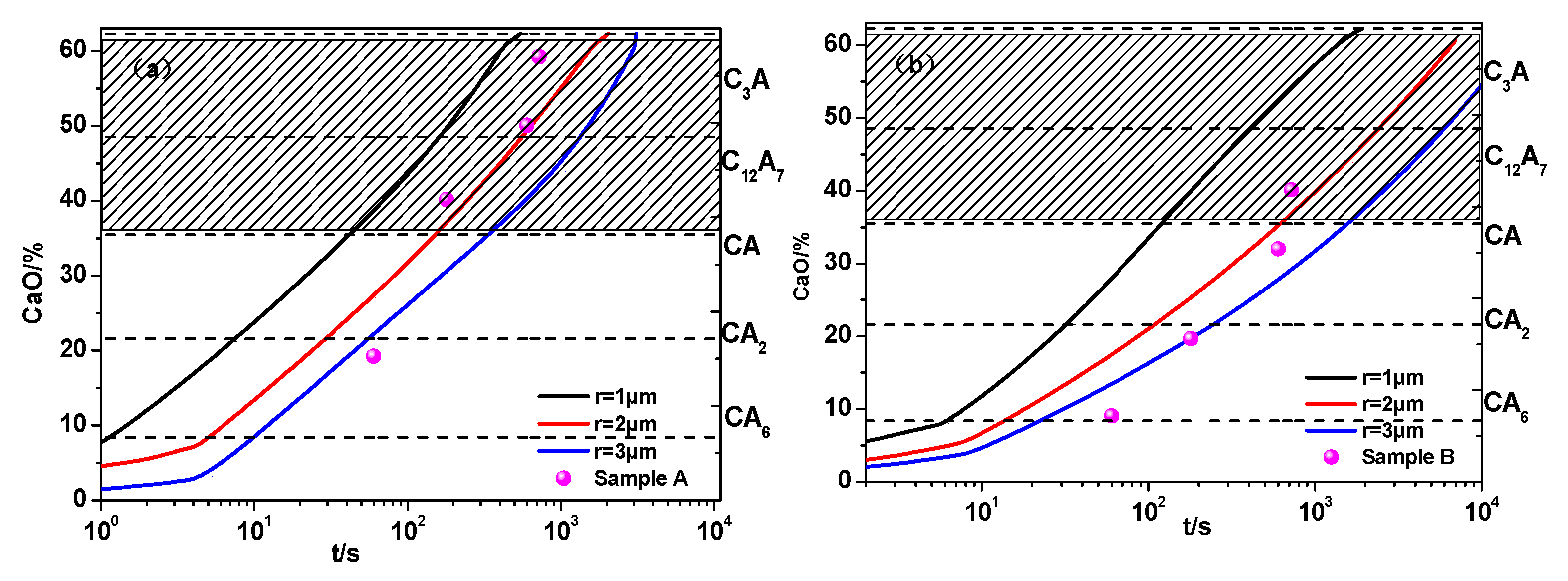
4.7. Modeling Verification
5. Conclusions
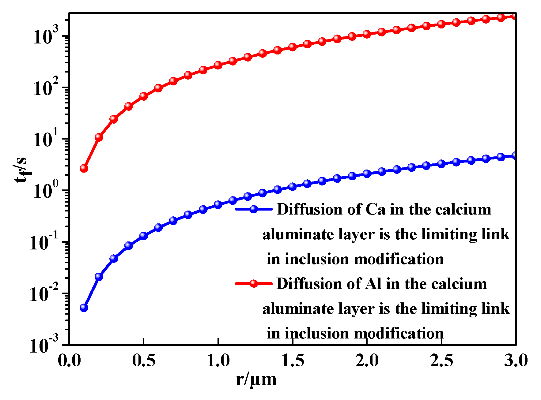
- The diffusion of Al in the inclusion layer was the limiting link in the inclusion modification process. The modification time increased linearly with increasing oxygen content and decreased with increasing calcium content in molten steel. The change of modification time with increasing Al content was very small. The Ca concentration in molten steel had the greatest influence on the modification time of inclusions;
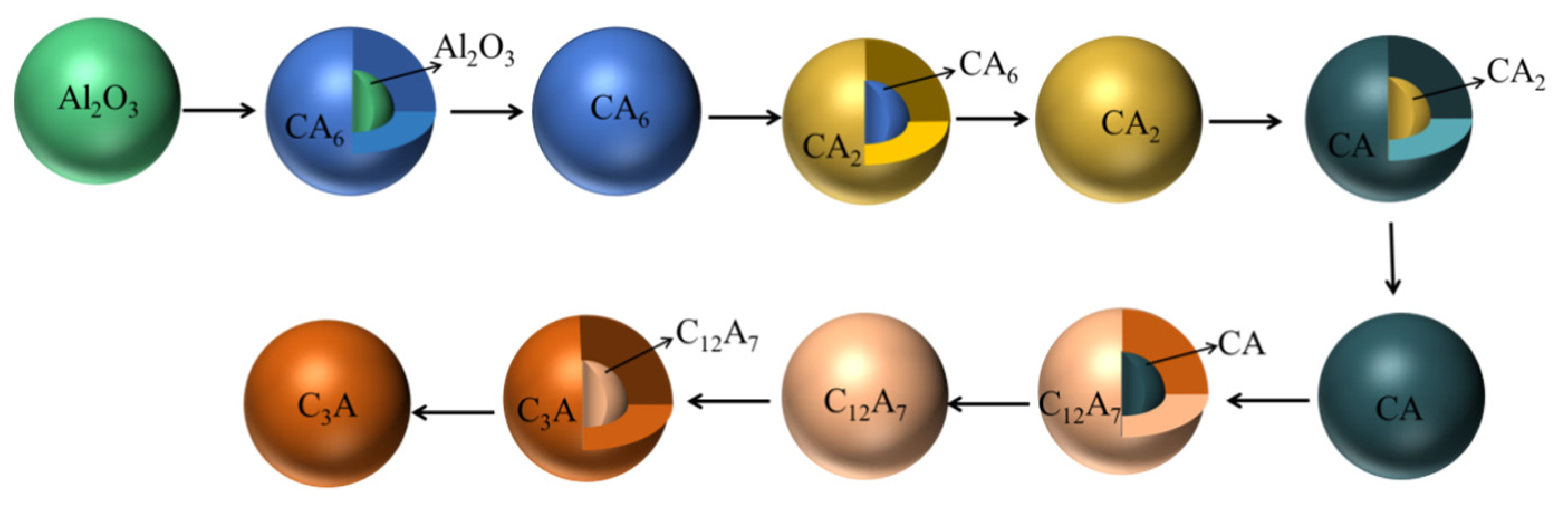
- The modification times for inclusions tended to be longer in the transformation of higher CaO-containing calcium aluminate. The modification of Al2O3 into CA6 was fastest, while the most time was needed to modify CA into C12A7;
- It took about six times time longer at the later stage of inclusion modification than at the early stage. The complete modification times for inclusions increased with the square of their radii. The complete modification times were prolonged by four times when the radii of unmodified inclusions doubled;
- The model calculation was in good agreement with experimental results. The inclusions with a 1 μm radius evolving from Al2O3 to CA6 took no longer than 1s. The modification of Al2O3 inclusions in sample A was much faster than in sample B. It took about 1000 s for inclusion with a 3 μm radius to modify Al2O3 into liquid calcium aluminate in sample A and about 6000 s for that in sample B.
Author Contributions
Funding
Institutional Review Board Statement
Informed Consent Statement
Data Availability Statement
Conflicts of Interest
References
- Li, X.D.; Deng, S.; Yang, Y.B. Production practice of plasticity control of inclusions in CaO–Al2O3–SiO2 system of SWRH82B hard wire steel. Metall. China 2018, 28, 61–66. [Google Scholar]
- Elwazri, A.; Wanjara, P.; Yue, S. Measurement of pearlite interlamellar spacing in hypereutectoid steels. Mater. Charact. 2005, 54, 473–478. [Google Scholar] [CrossRef]
- Tanaka, Y.; Pahlevani, F.; Kitamura, S.-Y.; Privat, K.; Sahajwalla, V. Behaviour of Sulphide and Non-alumina-Based Oxide Inclusions in Ca-Treated High-Carbon Steel. Met. Mater. Trans. A 2020, 51, 1384–1394. [Google Scholar] [CrossRef]
- Atienza, J.M.; Elices, M.; Ruiz-Hervias, J.; Caballero, L.; Valiente, A. Residual stresses and durability in cold drawn eutectoid steel wires. Met. Mater. Int. 2007, 13, 139–143. [Google Scholar] [CrossRef]
- Handoko, W.; Anurag, A.; Pahlevani, F. Effect of selective-precipitations process on the corrosion resistance and hardness of dual-phase high-carbon steel. Sci. Rep. 2019, 9, 15631. [Google Scholar] [CrossRef] [PubMed]
- Wang, G.D.; Lv, Y.W. Research on inclusion control and rolling process optimization of 82B hard wire steel. Metall. China 2012, 22, 15–17, 21. [Google Scholar]
- Robinson, S.W.; Martin, I.W.; Pickering, F.B. Formation of alumina in steel and its dissemination during mechanical working. Metals Technol. 1979, 6, 157–169. [Google Scholar] [CrossRef]
- Jiang, Z.; Tieu, A.; Zhang, X.; Lu, C.; Sun, W. Finite element simulation of cold rolling of thin strip. J. Mater. Process. Technol. 2003, 140, 542–547. [Google Scholar] [CrossRef]
- Abraham, S.; Bodnar, R.; Raines, J. Inclusion engineering and metallurgy of calcium treatment. J. Iron. Steel. Res. Int. 2018, 1, 1243–1257. [Google Scholar] [CrossRef]
- Verma, N.; Pistorius, P.C.; Fruehan, R.J.; Potter, M.; Lind, M.; Story, S. Transient Inclusion Evolution During Modification of Alumina Inclusions by Calcium in Liquid Steel: Part I. Background, Experimental Techniques and Analysis Methods. Metall. Mater. Trans. B. 2011, 42, 711–719. [Google Scholar] [CrossRef]
- Yang, G.W.; Wang, X.H.; Huang, F.X. Influence of Calcium Addition on Inclusions in LCAK Steel with Ultralow Sulfur Content. Metall. Mater. Trans. B 2015, 46, 145–154. [Google Scholar] [CrossRef]
- Zhang, L.; Liu, Y.; Zhang, Y. Transient Evolution of Nonmetallic Inclusions During Calcium Treatment of Molten Steel. Metall. Mater. Trans. B 2018, 49, 1–19. [Google Scholar] [CrossRef]
- Lamut, J.; Falkus, J.; Jurjevec, B. Influence of Inclusions Modification on Nozzle Clogging. Arch. Metall. Mater. 2012, 57, 319–324. [Google Scholar] [CrossRef]
- Zheng, H.-Y.; Guo, S.-Q.; Qiao, M.-R.; Qin, L.-B.; Zou, X.-J.; Ren, Z.-M. Study on the modification of inclusions by Ca treatment in GCr18Mo bearing steel. Adv. Manuf. 2019, 7, 438–447. [Google Scholar] [CrossRef]
- Holappa, L.; Hämäläinen, M.; Liukkonen, M.; Lind, M. Thermodynamic examination of inclusion modification and precipitation from calcium treatment to solidified steel. Ironmak. Steelmak. 2003, 30, 111–115. [Google Scholar] [CrossRef]
- Xu, J.; Huang, F.; Wang, X. Formation Mechanism of CaS–Al2O3 Inclusions in Low Sulfur Al-Killed Steel After Calcium Treatment. Metall. Mater. Trans. B 2016, 47, 1217–1227. [Google Scholar] [CrossRef]
- Lu, D.; Irons, G.A.; Lu, W. Kinetics and mechanisms of calcium dissolution and modification of oxide and sulphide inclusions in steel. Ironmak. Steelmak. 1994, 21, 362–372. [Google Scholar]
- Higuchi, Y.; Numata, M.; Fukagawa, S.; Shinme, K. Inclusion Modification by Calcium Treatment. ISIJ Int. 1996, 36, S151–S154. [Google Scholar] [CrossRef] [Green Version]
- Visser, H.-J.; Boom, R.; Biglari, M. Simulation of the calcium treatment of aluminium killed steel. Rev. Métall. 2008, 105, 172–180. [Google Scholar] [CrossRef]
- Ito, Y.I.; Suda, M.; Kato, Y.; Nakato, H. Kinetics of Shape Control of Alumina Inclusions with Calcium Treatment in Line Pipe Steel for Sour Service. ISIJ Int. 1996, 36, S148–S150. [Google Scholar] [CrossRef] [Green Version]
- Han, Z.; Liu, L.; Lind, M. Holappa Mechanism and Kinetics of Transformation of Alumina Inclusions by Calcium Treatment. Acta. Metall. Sin. 2006, 19, 1–8. [Google Scholar] [CrossRef]
- Park, J.H.; Lee, S.-B.; Kim, D.S. Inclusion control of ferritic stainless steel by aluminum deoxidation and calcium treatment. Met. Mater. Trans. A 2005, 36, 67–73. [Google Scholar] [CrossRef]
- Galindo, A.; Irons, G.; Sun, S. Modeling of the Trajectory of Slag and Metal Chemistry during Ladle Treatment Used to Predict Changes in the Primary Inclusion Type. In Proceedings of the International Congress on the Science & Technology of Steelmaking, Beijing, China, 12–14 May 2015. [Google Scholar]
- Tabatabaei, Y.; Coley, K.S.; Irons, G.A.; Sun, S. A Multilayer Model for Alumina Inclusion Transformation by Calcium in the Ladle Furnace. Metall. Mater. Trans. B 2018, 49, 375–387. [Google Scholar] [CrossRef]
- Turkdogan, E.T. Proceedings of 1st International Calcium Treatment Symposium, University of Strathclyde, Glasgow, Scotland, 1988; The Institute of Metals: London, UK, 1988; pp. 3–13. [Google Scholar]
- Ye, G.; Jönsson, P.; Lund, T. Thermodynamics and Kinetics of the Modification of Al2O3 Inclusions. ISIJ Int. 1996, 36, S105–S108. [Google Scholar] [CrossRef]
- Lei, H.; He, J.C. Mathematical Models on Inclusion Dynamics Behavior in the Molten Steel. Chin. J. Process Eng. 2010, 10, 288–292. [Google Scholar]
- Min, Y.; Zhang, Q.; Xu, H.; Xu, J.; Liu, C. Formation and Evolution of Inclusions with Different Adding Order of Magnesium and Sulfur in Al-Killed Free-Cutting Steel. Metals 2018, 8, 1064. [Google Scholar] [CrossRef] [Green Version]
- Tabatabaei, Y.; Coley, K.S.; Irons, G.A.; Sun, S. A Kinetic Model for Modification of MgAl2O4 Spinel Inclusions During Calcium Treatment in the Ladle Furnace. Metall. Mater. Trans. B 2018, 49, 2744–2756. [Google Scholar] [CrossRef]
- Guo, J.; Cheng, S.S.; Cheng, Z.J. Kinetic modeling of alumina inclusion modification in Al – Killed steel after Ca treatment. J. Univ. Sci. Technol. B 2014, 36, 424–431. [Google Scholar]
- Itoh, H.; Hino, M. Thermodynamics on the formation of spinel nonmetallic inclusion in liquid steel. Metall. Mater. Trans. B 1997, 28, 953–956. [Google Scholar] [CrossRef]
- Wang, L.Z.; Yang, S.F.; Li, J.S. Effect of Mg Addition on the Refinement and Homogenized Distribution of Inclusions in Steel with Different Al Contents. Metall. Mater. Trans. B 2017, 48, 805–818. [Google Scholar] [CrossRef]


| Raw material | Fe | Si | Mn | S | C | Ca | Al | Others |
|---|---|---|---|---|---|---|---|---|
| Industrial pure iron | 99.7 | 0.02 | 0.03 | 0.0002 | 0.0018 | - | 0.001 | 0.2445 |
| Electrolytic manganese | - | - | 99.999 | - | - | - | - | 0.001 |
| Si–Fe alloy | 21 | 78 | 0.4 | 0.02 | 0.1 | - | - | 0.48 |
| Al alloy | 0.7 | 0.8 | 0.15 | - | - | - | 96.94 | 1.41 |
| Si–Ca alloy | - | 57.13 | 20.44 | - | 0.83 | 19.56 | 2.02 | 0.02 |
| QT400 | 95.8 | 0.17 | 0.5 | 0.01 | 3.45 | - | - | 0.07 |
| Number | C | Si | Mn | S | O | Al | Ca |
|---|---|---|---|---|---|---|---|
| A | 0.652 | 0.183 | 0.312 | 0.0021 | 0.0051 | 0.0042 | 0.0025 |
| B | 0.652 | 0.183 | 0.300 | 0.0017 | 0.0061 | 0.0038 | 0.0017 |
| C | Si | Mn | S | Al | O | Ca | |
|---|---|---|---|---|---|---|---|
| Ca | −0.34 | −0.095 | −0.007 | −28 | −0.072 | −780 | −0.002 |
| O | −0.42 | −0.066 | −0.021 | −0.13 | −1.17 | −0.17 | −313 |
| Al | 0.091 | 0.056 | −0.004 | 0.035 | −0.043 | −1.98 | −0.047 |
| Steel | aCa | aAl |
|---|---|---|
| A | 1.31 × 10⁻⁷ | 0.0048 |
| B | 1.52 × 10⁻⁸ | 0.0043 |
Publisher’s Note: MDPI stays neutral with regard to jurisdictional claims in published maps and institutional affiliations. |
© 2021 by the authors. Licensee MDPI, Basel, Switzerland. This article is an open access article distributed under the terms and conditions of the Creative Commons Attribution (CC BY) license (http://creativecommons.org/licenses/by/4.0/).
Share and Cite
Xi, Z.; Li, C.; Wang, L. A Kinetic Model for the Modification of Al2O3 Inclusions during Calcium Treatment in High-Carbon Hard Wire Steel. Materials 2021, 14, 1305. https://doi.org/10.3390/ma14051305
Xi Z, Li C, Wang L. A Kinetic Model for the Modification of Al2O3 Inclusions during Calcium Treatment in High-Carbon Hard Wire Steel. Materials. 2021; 14(5):1305. https://doi.org/10.3390/ma14051305
Chicago/Turabian StyleXi, Zuobing, Changrong Li, and Linzhu Wang. 2021. "A Kinetic Model for the Modification of Al2O3 Inclusions during Calcium Treatment in High-Carbon Hard Wire Steel" Materials 14, no. 5: 1305. https://doi.org/10.3390/ma14051305