
Evaluation of Smeared Constitutive Laws for Tensile Concrete to Predict the Cracking of RC Beams under Torsion with Smeared Truss Model


Abstract
:1. Introduction
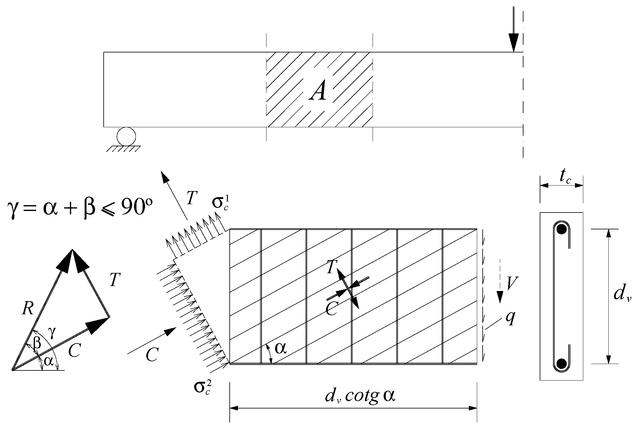
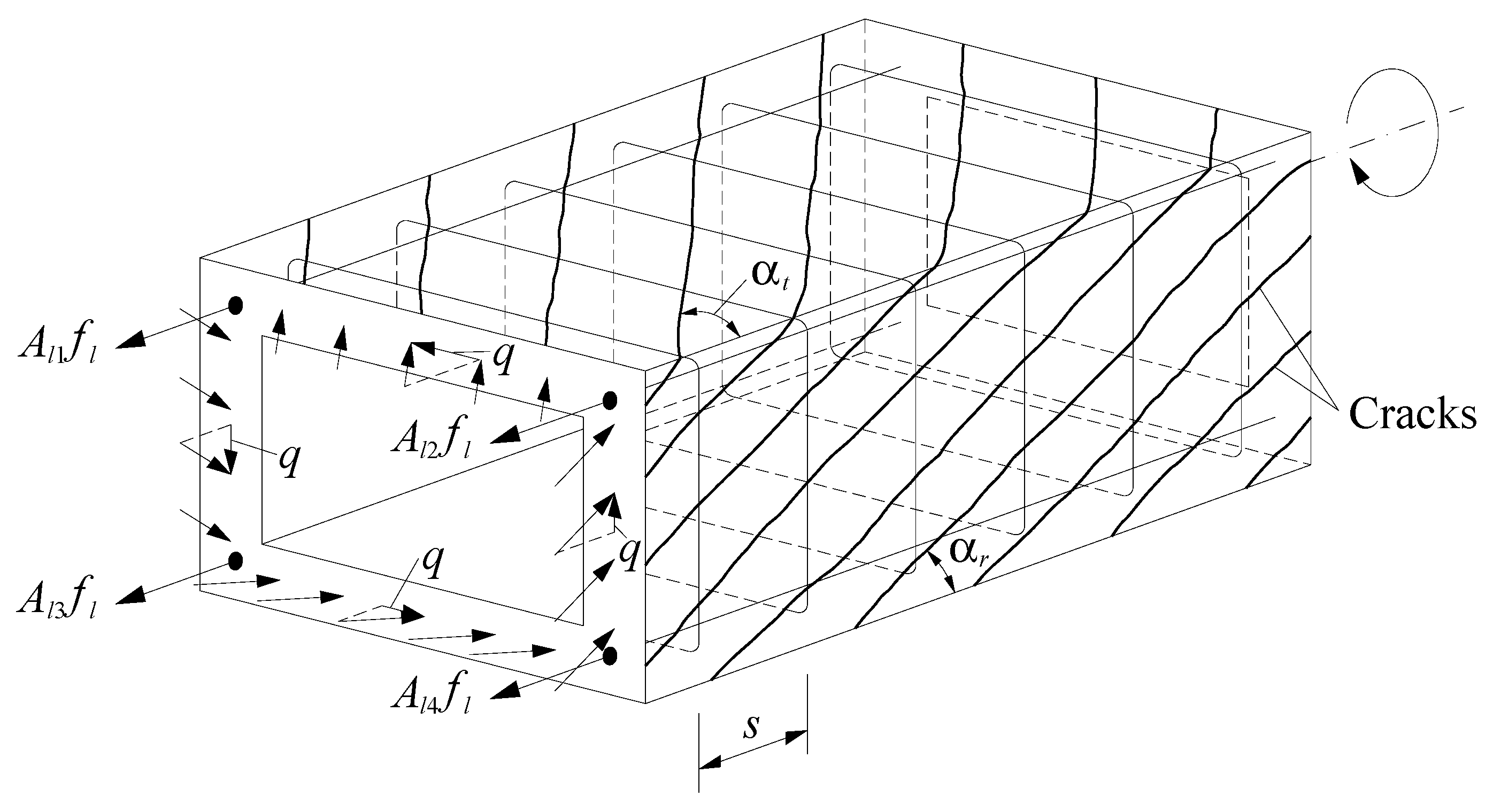
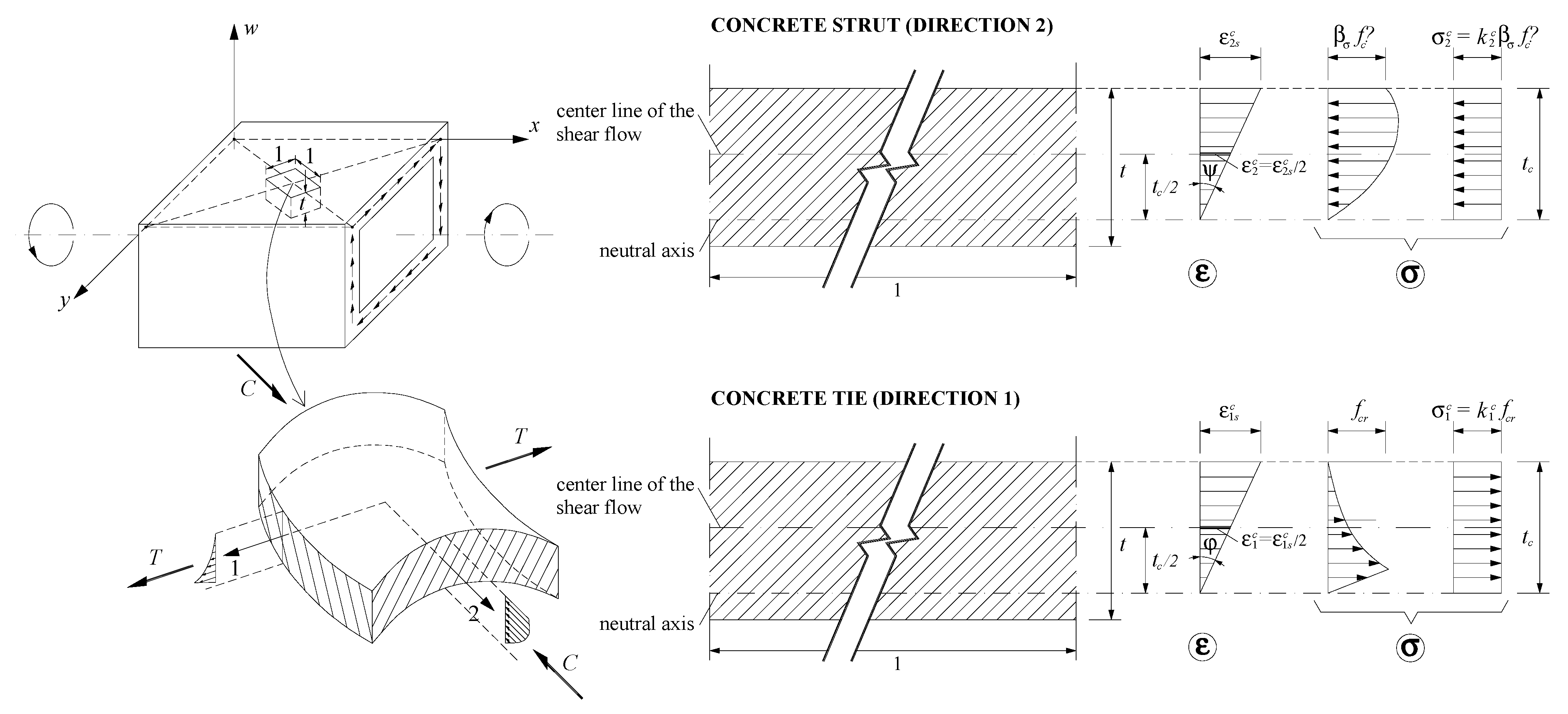
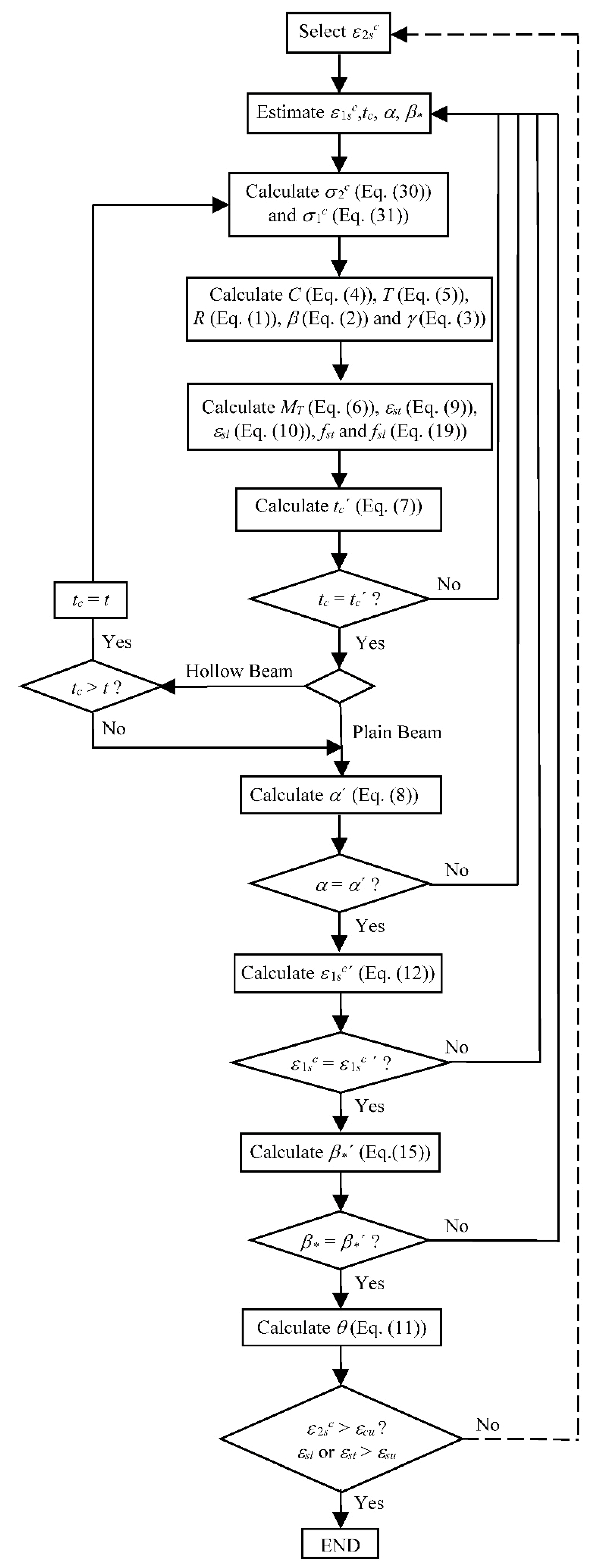
2. The Generalized Softened Variable Angle Truss-Model
- if the RC hollow beam has a “thin wall”;
- if the RC hollow beam has a “thick wall”.
3. Smeared Constitutive Laws for Tensile Concrete
3.1. Law l1—Cervenka in 1985
3.2. Law l2—Vecchio and Collins in 1986
3.3. Law l3—Hsu in 1991
3.4. Law l4—Belarbi and Hsu in 1994
3.5. Law l5—Collins and Colaborators in 1996
3.6. Law l6—Vecchio in 2000
3.7. Law l7—Bentz in 2005
3.8. Law l8—Stramandinoli and Rovere in 2008
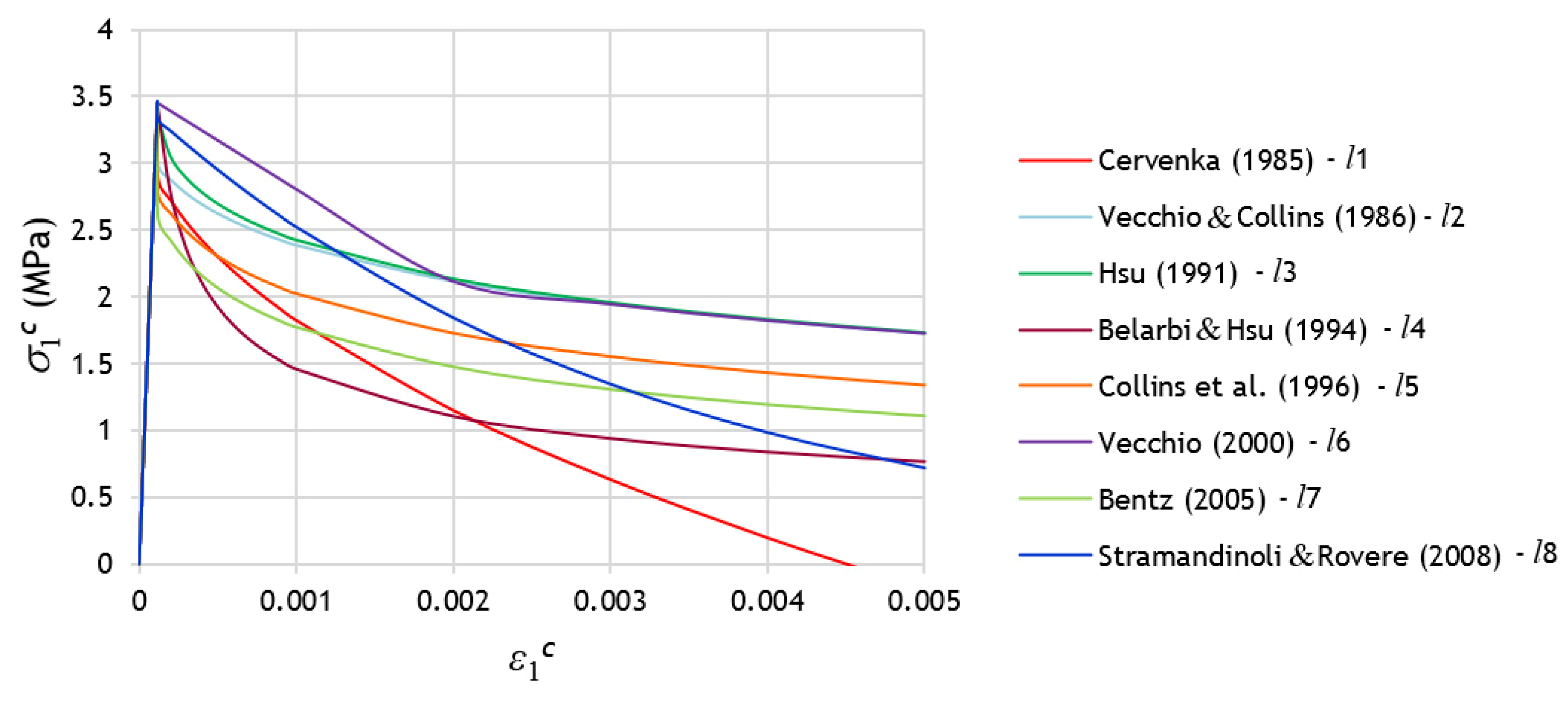
3.9. Comparison between the Smeared Constitutive Laws
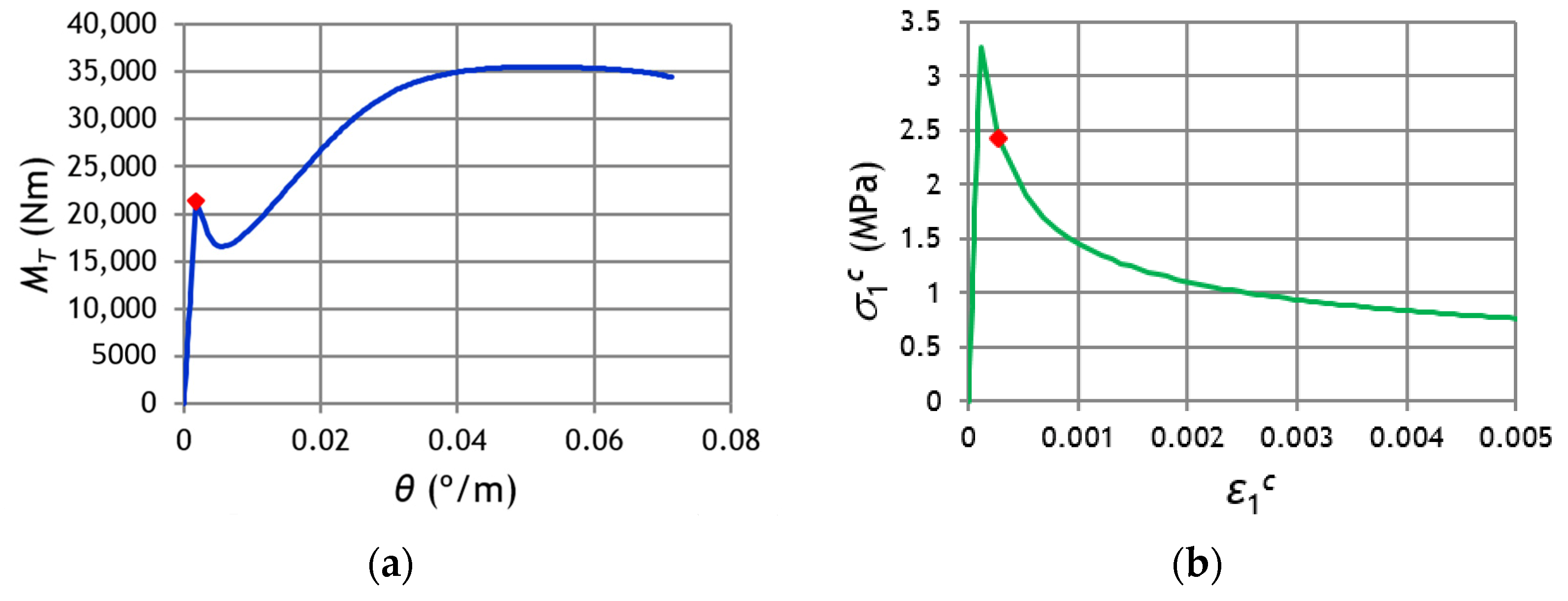
 ”) corresponds to the effective cracking torque, which is reached for a strain > , i.e., in the descending branch of the smeared σ—ε curve for tensile concrete. This explains why different smeared — curves for tensile concrete incorporated in the GSVATM will lead to different coordinates for the cracking torque (cracking torque and corresponding twist).
 4. Comparison with Experimental Results
 ” for RC plain beams and “
  ” for RC hollow beams.
5. Conclusions
- (1)
- The different proposals for the smeared constitutive law for tensile concrete analyzed in this study lead to high differences in the shape of the postpeak descending branch of the corresponding smeared — curves;
- (2)
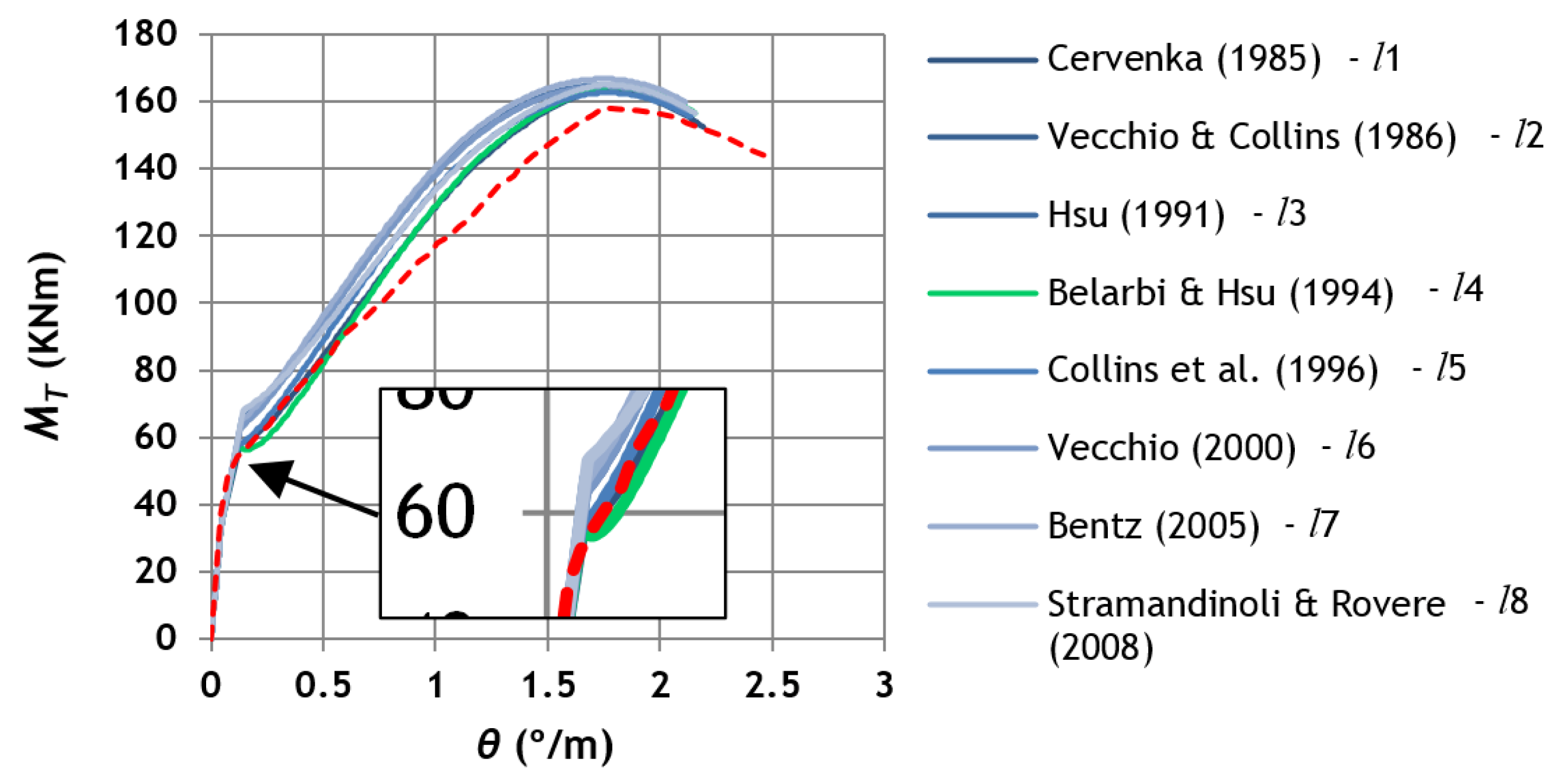
- The obtained results confirm that the predicted response of the RC beams under torsion, for the transition from the uncracked stage to the cracked stage highly depends on the smeared constitutive law for tensile concrete incorporated into the model;
- (3)
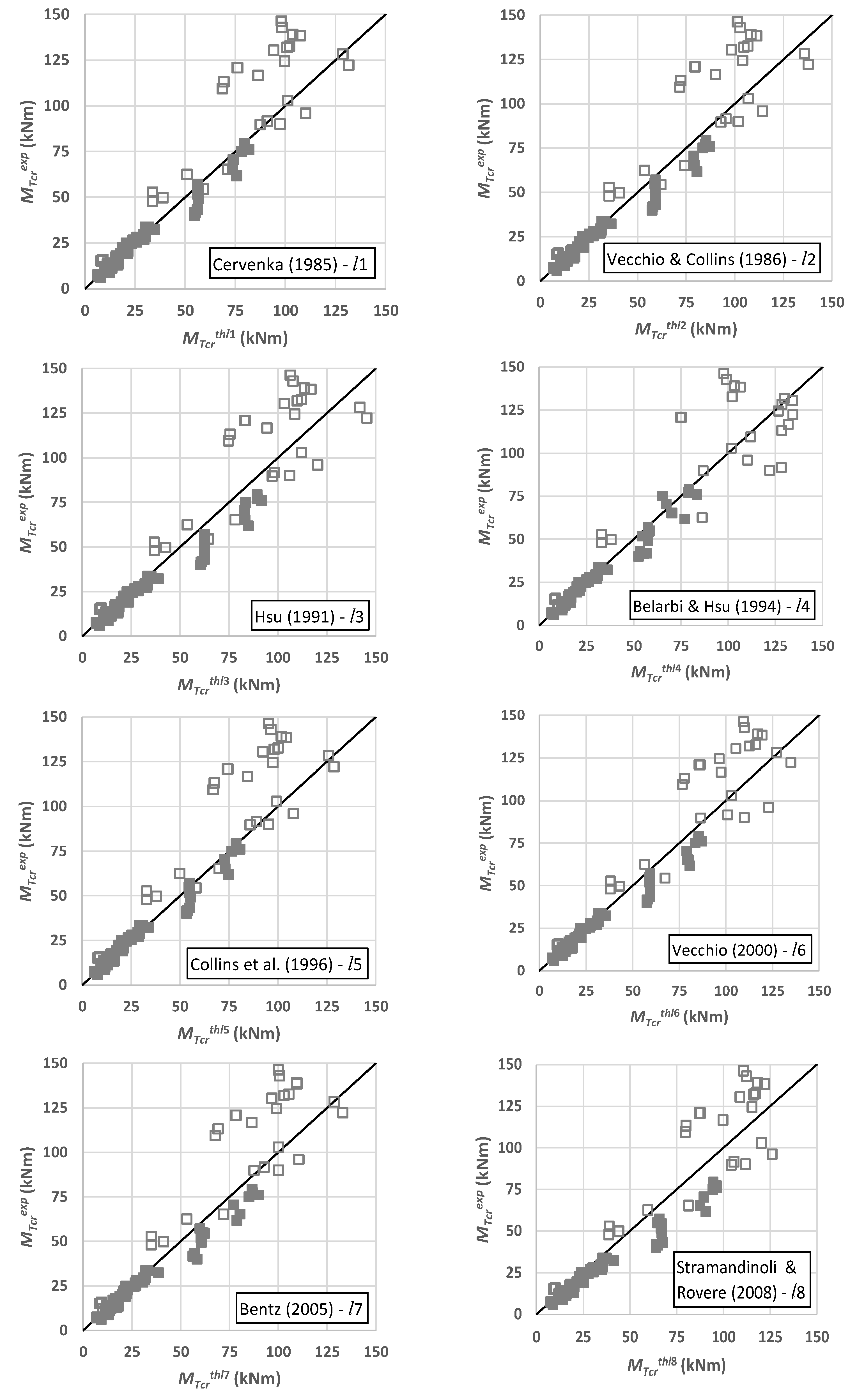
- The predictions for the cracking torque of the RC plain beams are better than the same ones for the RC hollow beams for which higher variability of the results is observed, as also reported in previous studies;
- (4)
- Regardless of the used smeared constitutive law for tensile concrete, the cracking twist is not very well predicted. Namely, higher variability of the results is observed, as also reported in previous studies;
- (5)
- Among the studied smeared constitutive laws for tensile concrete, the one proposed by Belarbi and Hsu in 1994 allows us to reliably predict the cracking torque of the RC beams under torsion, regardless of the cross-section type (plain or hollow). This result confirms the validity of several previous studies having incorporated this constitutive law in the used smeared truss models.
Author Contributions
Funding
Institutional Review Board Statement
Informed Consent Statement
Data Availability Statement
Conflicts of Interest
Appendix A

| Beam | cm | cm | cm | cm | cm | cm2/m | cm2 | % | % | MPa | MPa | MPa | % | |
|---|---|---|---|---|---|---|---|---|---|---|---|---|---|---|
| B3 [35] | P | 25.4 | 38.1 | - | 21.6 | 34.3 | 10.16 | 11.36 | 1.17 | 1.17 | 320 | 328 | 28.1 | 0.20 |
| B4 [35] | P | 25.4 | 38.1 | - | 21.6 | 34.3 | 14.01 | 15.48 | 1.62 | 1.60 | 323 | 320 | 29.2 | 0.20 |
| B5 [35] | P | 25.4 | 38.1 | - | 21.6 | 34.3 | 18.47 | 20.39 | 2.13 | 2.11 | 321 | 332 | 30.6 | 0.20 |
| B6 [35] | P | 25.4 | 38.1 | - | 21.6 | 34.3 | 22.58 | 25.81 | 2.61 | 2.67 | 323 | 332 | 28.8 | 0.20 |
| B7 [35] | P | 25.4 | 38.1 | - | 21.6 | 34.3 | 10.16 | 5.16 | 1.17 | 0.53 | 319 | 320 | 26.0 | 0.19 |
| B8 [35] | P | 25.4 | 38.1 | - | 21.6 | 34.3 | 22.58 | 5.16 | 2.61 | 0.53 | 320 | 322 | 26.8 | 0.19 |
| B9 [35] | P | 25.4 | 38.1 | - | 21.6 | 34.3 | 4.66 | 11.36 | 0.54 | 1.17 | 343 | 319 | 28.8 | 0.20 |
| C4 [35] | P | 25.4 | 25.4 | - | 21.6 | 21.6 | 13.11 | 11.36 | 1.76 | 1.76 | 328 | 337 | 27.2 | 0.20 |
| C5 [35] | P | 25.4 | 25.4 | - | 21.6 | 21.6 | 17.67 | 15.48 | 2.37 | 2.40 | 329 | 328 | 27.2 | 0.20 |
| C6 [35] | P | 25.4 | 25.4 | - | 21.6 | 21.6 | 23.91 | 20.39 | 3.20 | 3.16 | 328 | 316 | 27.6 | 0.20 |
| G3 [35] | P | 25.4 | 50.8 | - | 21.6 | 47.0 | 8.29 | 11.36 | 0.88 | 0.88 | 328 | 339 | 26.8 | 0.19 |
| G4 [35] | P | 25.4 | 50.8 | - | 21.6 | 47.0 | 11.29 | 15.48 | 1.20 | 1.20 | 321 | 326 | 28.3 | 0.20 |
| G5 [35] | P | 25.4 | 50.8 | - | 21.6 | 47.0 | 15.05 | 20.39 | 1.60 | 1.58 | 328 | 331 | 26.9 | 0.19 |
| G7 [35] | P | 25.4 | 50.8 | - | 21.6 | 47.0 | 8.84 | 12.00 | 0.94 | 0.93 | 323 | 319 | 31.0 | 0.20 |
| G8 [35] | P | 25.4 | 50.8 | - | 21.6 | 47.0 | 12.32 | 17.03 | 1.31 | 1.32 | 329 | 322 | 28.3 | 0.20 |
| I3 [35] | P | 25.4 | 38.1 | - | 21.6 | 34.3 | 10.16 | 11.36 | 1.17 | 1.17 | 334 | 343 | 44.8 | 0.23 |
| I4 [35] | P | 25.4 | 38.1 | - | 21.6 | 34.3 | 14.01 | 15.48 | 1.62 | 1.60 | 326 | 315 | 45.0 | 0.23 |
| I5 [35] | P | 25.4 | 38.1 | - | 21.6 | 34.3 | 18.47 | 20.39 | 2.13 | 2.11 | 326 | 310 | 45.0 | 0.23 |
| I6 [35] | P | 25.4 | 38.1 | - | 21.6 | 34.3 | 22.58 | 25.81 | 2.61 | 2.67 | 329 | 326 | 45.8 | 0.23 |
| J1 [35] | P | 25.4 | 38.1 | - | 21.6 | 34.3 | 4.66 | 5.16 | 0.54 | 0.53 | 346 | 328 | 14.3 | 0.16 |
| J2 [35] | P | 25.4 | 38.1 | - | 21.6 | 34.3 | 7.21 | 8.00 | 0.83 | 0.83 | 341 | 320 | 14.6 | 0.16 |
| J3 [35] | P | 25.4 | 38.1 | - | 21.6 | 34.3 | 10.16 | 11.36 | 1.17 | 1.17 | 337 | 389 | 16.9 | 0.17 |
| J4 [35] | P | 25.4 | 38.1 | - | 21.6 | 34.3 | 14.01 | 15.48 | 1.62 | 1.60 | 332 | 324 | 16.8 | 0.17 |
| K2 [35] | P | 15.2 | 49.5 | - | 11.4 | 45.7 | 6.77 | 7.74 | 1.03 | 1.03 | 338 | 336 | 30.6 | 0.20 |
| K3 [35] | P | 15.2 | 49.5 | - | 11.4 | 45.7 | 10.42 | 12.00 | 1.58 | 1.59 | 321 | 316 | 29.0 | 0.20 |
| K4 [35] | P | 15.2 | 49.5 | - | 11.4 | 45.7 | 15.05 | 17.03 | 2.28 | 2.26 | 340 | 344 | 28.6 | 0.20 |
| M1 [35] | P | 25.4 | 38.1 | - | 21.6 | 34.3 | 4.76 | 8.00 | 0.55 | 0.83 | 353 | 326 | 29.9 | 0.20 |
| M2 [35] | P | 25.4 | 38.1 | - | 21.6 | 34.3 | 6.77 | 11.36 | 0.78 | 1.17 | 357 | 329 | 30.6 | 0.20 |
| M3 [35] | P | 25.4 | 38.1 | - | 21.6 | 34.3 | 9.24 | 15.48 | 1.07 | 1.60 | 326 | 322 | 26.8 | 0.29 |
| M4 [35] | P | 25.4 | 38.1 | - | 21.6 | 34.3 | 12.33 | 20.39 | 1.42 | 2.11 | 327 | 319 | 26.6 | 0.19 |
| M5 [35] | P | 25.4 | 38.1 | - | 21.6 | 34.3 | 15.63 | 25.81 | 1.81 | 2.67 | 331 | 335 | 28.0 | 0.20 |
| M6 [35] | P | 25.4 | 38.1 | - | 21.6 | 34.3 | 15.63 | 30.58 | 1.81 | 3.16 | 341 | 318 | 29.4 | 0.20 |
| N1 [35] | P | 15.2 | 30.5 | - | 13.0 | 28.3 | 3.50 | 2.84 | 0.62 | 0.61 | 341 | 352 | 29.5 | 0.20 |
| N1a [35] | P | 15.2 | 30.5 | - | 13.0 | 28.3 | 3.50 | 2.84 | 0.62 | 0.61 | 345 | 346 | 28.7 | 0.20 |
| N2 [35] | P | 15.2 | 30.5 | - | 13.0 | 28.3 | 6.35 | 5.16 | 1.13 | 1.11 | 338 | 331 | 30.4 | 0.20 |
| N2a [35] | P | 15.2 | 30.5 | - | 13.0 | 28.3 | 6.21 | 1.61 | 1.10 | 1.11 | 361 | 333 | 28.4 | 0.20 |
| N3 [35] | P | 15.2 | 30.5 | - | 13.0 | 28.3 | 5.08 | 4.26 | 0.90 | 0.92 | 352 | 352 | 27.3 | 0.20 |
| N4 [35] | P | 15.2 | 30.5 | - | 13.0 | 28.3 | 7.98 | 6.58 | 1.42 | 1.42 | 356 | 341 | 27.3 | 0.20 |
| A2 [36] | P | 25.4 | 25.4 | - | 22.2 | 22.2 | 7.82 | 5.16 | 1.08 | 0.80 | 285 | 380 | 38.2 | 0.22 |
| A3 [36] | P | 25.4 | 25.4 | - | 21.9 | 21.9 | 8.94 | 8.00 | 1.22 | 1.24 | 360 | 352 | 39.4 | 0.22 |
| A4 [36] | P | 25.4 | 25.4 | - | 21.9 | 21.9 | 12.42 | 11.36 | 1.69 | 1.76 | 360 | 351 | 39.2 | 0.22 |
| B3 [36] | P | 17.8 | 35.6 | - | 14.3 | 32.1 | 8.60 | 8.00 | 1.26 | 1.27 | 360 | 352 | 38.6 | 0.22 |
| B4 [36] | P | 17.8 | 35.6 | - | 14.3 | 32.1 | 11.76 | 11.36 | 1.73 | 1.80 | 360 | 351 | 38.5 | 0.22 |
| B5UR1 [37] | P | 20.3 | 30.5 | - | 16.5 | 26.7 | 6.56 | 5.16 | 0.92 | 0.83 | 373 | 386 | 39.6 | 0.20 |
| B9UR1 [37] | P | 20.3 | 30.5 | - | 16.5 | 26.7 | 6.56 | 5.16 | 0.92 | 0.83 | 373 | 386 | 75.0 | 0.27 |
| B12UR1 [37] | P | 20.3 | 30.5 | - | 16.5 | 26.7 | 6.56 | 5.16 | 0.92 | 0.83 | 399 | 386 | 80.6 | 0.27 |
| B14UR1 [37] | P | 20.3 | 30.5 | - | 16.5 | 26.7 | 6.56 | 5.16 | 0.92 | 0.83 | 386 | 386 | 93.9 | 0.29 |
| B12UR2 [37] | P | 20.3 | 30.5 | - | 16.5 | 26.7 | 6.95 | 5.16 | 0.97 | 0.83 | 386 | 386 | 76.2 | 0.27 |
| B12UR3 [37] | P | 20.3 | 30.5 | - | 16.5 | 26.7 | 7.46 | 6.58 | 1.04 | 1.06 | 386 | 380 | 72.9 | 0.26 |
| B12UR4 [37] | P | 20.3 | 30.5 | - | 16.5 | 26.7 | 7.88 | 7.74 | 1.10 | 1.25 | 386 | 373 | 75.9 | 0.27 |
| B12UR5 [37] | P | 20.3 | 30.5 | - | 16.5 | 26.7 | 10.13 | 8.00 | 1.41 | 1.29 | 386 | 380 | 76.7 | 0.27 |
| H-06-12 [38] | P | 35.0 | 50.0 | - | 30.0 | 45.0 | 7.10 | 20.65 | 0.61 | 1.18 | 440 | 410 | 78.5 | 0.27 |
| H-07-10 [38] | P | 35.0 | 50.0 | - | 30.0 | 45.0 | 7.89 | 17.03 | 0.68 | 0.97 | 420 | 500 | 68.4 | 0.26 |
| H-07-16 [38] | P | 35.0 | 50.0 | - | 30.0 | 45.0 | 7.89 | 28.39 | 0.68 | 1.62 | 420 | 500 | 68.4 | 0.26 |
| H-12-12 [38] | P | 35.0 | 50.0 | - | 30.0 | 45.0 | 14.19 | 20.65 | 1.22 | 1.18 | 440 | 410 | 78.5 | 0.27 |
| H-12-16 [38] | P | 35.0 | 50.0 | - | 30.0 | 45.0 | 14.19 | 28.39 | 1.22 | 1.62 | 440 | 520 | 78.5 | 0.27 |
| H-14-10 [38] | P | 35.0 | 50.0 | - | 30.0 | 45.0 | 16.13 | 17.03 | 1.38 | 0.97 | 360 | 500 | 68.4 | 0.26 |
| H-20-20 [38] | P | 35.0 | 50.0 | - | 30.0 | 45.0 | 23.46 | 34.06 | 2.01 | 1.95 | 440 | 560 | 78.5 | 0.27 |
| N-06-06 [38] | P | 35.0 | 50.0 | - | 30.0 | 45.0 | 7.10 | 12.00 | 0.61 | 0.69 | 440 | 440 | 35.5 | 0.21 |
| N-06-12 [38] | P | 35.0 | 50.0 | - | 30.0 | 45.0 | 7.10 | 20.65 | 0.61 | 1.18 | 440 | 410 | 35.5 | 0.21 |
| N-07-10 [38] | P | 35.0 | 50.0 | - | 30.0 | 45.0 | 7.89 | 17.03 | 0.68 | 0.97 | 420 | 500 | 33.5 | 0.21 |
| N-07-16 [38] | P | 35.0 | 50.0 | - | 30.0 | 45.0 | 7.89 | 28.39 | 0.68 | 1.62 | 420 | 500 | 33.5 | 0.21 |
| N-12-12 [38] | P | 35.0 | 50.0 | - | 30.0 | 45.0 | 14.19 | 20.65 | 1.22 | 1.18 | 440 | 410 | 35.5 | 0.21 |
| N-12-16 [38] | P | 35.0 | 50.0 | - | 30.0 | 45.0 | 14.19 | 28.39 | 1.22 | 1.62 | 440 | 520 | 35.5 | 0.21 |
| N-14-10 [38] | P | 35.0 | 50.0 | - | 30.0 | 45.0 | 16.13 | 17.03 | 1.38 | 0.97 | 360 | 500 | 33.5 | 0.21 |
| N-20-20 [38] | P | 35.0 | 50.0 | - | 30.0 | 45.0 | 23.46 | 34.06 | 2.01 | 1.95 | 440 | 560 | 35.5 | 0.21 |
| SW12-1 [39] | P | 15.0 | 120.0 | - | 10.0 | 115.0 | 3.93 | 11.31 | 0.55 | 1.26 | 459 | 480 | 44.2 | 0.23 |
| SW10-1 [39] | P | 15.0 | 100.0 | - | 10.0 | 95.0 | 3.93 | 9.05 | 0.55 | 1.21 | 459 | 499 | 29.5 | 0.20 |
| SW10-2 [39] | P | 15.0 | 100.0 | - | 9.8 | 94.8 | 7.54 | 9.05 | 1.05 | 1.21 | 480 | 480 | 44.2 | 0.23 |
| SW10-3 [39] | P | 15.0 | 100.0 | - | 9.8 | 94.8 | 11.31 | 9.05 | 1.58 | 1.21 | 499 | 499 | 29.5 | 0.20 |
| SW10-4 [39] | P | 15.0 | 100.0 | - | 9.4 | 94.4 | 16.08 | 16.08 | 2.23 | 2.14 | 497 | 497 | 33.8 | 0.21 |
| SW8-1 [39] | P | 15.0 | 80.0 | - | 10.2 | 75.2 | 4.02 | 7.07 | 0.57 | 1.18 | 433 | 459 | 29.5 | 0.20 |
| SW8-2 [39] | P | 15.0 | 80.0 | - | 9.8 | 74.8 | 11.31 | 7.07 | 1.59 | 1.18 | 499 | 459 | 29.5 | 0.20 |
| D3 [35] | H | 25.4 | 38.1 | 6.4 | 21.6 | 34.3 | 10.16 | 11.36 | 1.17 | 1.17 | 333 | 341 | 28.4 | 0.20 |
| D4 [35] | H | 25.4 | 38.1 | 6.4 | 21.6 | 34.3 | 14.01 | 15.48 | 1.62 | 1.60 | 333 | 330 | 30.6 | 0.20 |
| T0 [40] | H | 50.0 | 50.0 | 8.0 | 43.0 | 43.0 | 10.28 | 32.16 | 0.71 | 1.29 | 357 | 345 | 45.1 | 0.23 |
| T1 [40] | H | 50.0 | 50.0 | 8.0 | 45.4 | 45.4 | 10.28 | 18.10 | 0.75 | 0.72 | 357 | 357 | 35.3 | 0.21 |
| T2 [40] | H | 50.0 | 50.0 | 8.0 | 43.0 | 43.0 | 10.28 | 18.10 | 0.71 | 0.72 | 357 | 357 | 35.3 | 0.21 |
| T5 [40] | H | 80.0 | 40.0 | 8.0 | 73.0 | 33.0 | 10.28 | 10.00 | 0.68 | 0.31 | 513 | 529 | 47.1 | 0.23 |
| VH1 [41] | H | 32.4 | 32.4 | 8.0 | 30.4 | 30.4 | 2.88 | 3.46 | 0.33 | 0.33 | 447 | 447 | 17.2 | 0.17 |
| VH2 [41] | H | 32.4 | 32.4 | 8.0 | 30.4 | 30.4 | 5.76 | 6.91 | 0.67 | 0.66 | 447 | 447 | 17.2 | 0.17 |
| A2 [42] | H | 60.0 | 60.0 | 10.7 | 53.8 | 53.1 | 6.28 | 13.95 | 0.37 | 0.39 | 696 | 672 | 47.3 | 0.23 |
| A3 [42] | H | 60.0 | 60.0 | 10.9 | 53.5 | 53.5 | 8.27 | 18.10 | 0.49 | 0.50 | 715 | 672 | 46.2 | 0.23 |
| A4 [42] | H | 60.0 | 60.0 | 10.4 | 52.0 | 52.5 | 11.22 | 23.75 | 0.65 | 0.66 | 715 | 724 | 54.8 | 0.24 |
| A5 [42] | H | 60.0 | 60.0 | 10.4 | 52.8 | 52.8 | 14.14 | 30.66 | 0.83 | 0.85 | 672 | 724 | 53.1 | 0.24 |
| B2 [42] | H | 60.0 | 60.0 | 10.8 | 53.3 | 53.4 | 6.70 | 14.58 | 0.40 | 0.41 | 696 | 672 | 69.8 | 0.26 |
| B3 [42] | H | 60.0 | 60.0 | 10.9 | 53.5 | 53.7 | 11.22 | 23.75 | 0.67 | 0.66 | 715 | 724 | 77.8 | 0.27 |
| B4 [42] | H | 60.0 | 60.0 | 11.2 | 52.3 | 53.6 | 15.08 | 32.17 | 0.89 | 0.89 | 672 | 724 | 79.8 | 0.27 |
| B5 [42] | H | 60.0 | 60.0 | 11.7 | 51.8 | 51.8 | 18.85 | 40.21 | 1.09 | 1.12 | 672 | 724 | 76.4 | 0.27 |
| C2 [42] | H | 60.0 | 60.0 | 10.0 | 53.2 | 53.3 | 6.28 | 13.95 | 0.37 | 0.39 | 696 | 672 | 94.8 | 0.28 |
| C3 [42] | H | 60.0 | 60.0 | 10.3 | 54.5 | 54.0 | 10.47 | 23.75 | 0.63 | 0.66 | 715 | 724 | 91.6 | 0.28 |
| C4 [42] | H | 60.0 | 60.0 | 10.3 | 54.6 | 54.5 | 14.14 | 30.66 | 0.86 | 0.85 | 672 | 724 | 91.4 | 0.28 |
| C5 [42] | H | 60.0 | 60.0 | 10.4 | 54.0 | 54.3 | 17.40 | 36.69 | 1.05 | 1.02 | 672 | 724 | 96.7 | 0.28 |
| C6 [42] | H | 60.0 | 60.0 | 10.4 | 53.3 | 52.9 | 22.62 | 48.25 | 1.34 | 1.34 | 672 | 724 | 87.5 | 0.28 |
| A095c [26] | H | 49.7 | 71.1 | 14.5 | 43.7 | 65.1 | 9.93 | 13.16 | 0.61 | 0.37 | 381 | 371 | 35.1 | 0.21 |
| A120a [26] | H | 50.2 | 71.9 | 18.4 | 44.2 | 65.9 | 7.59 | 20.00 | 0.46 | 0.55 | 380 | 464 | 27.6 | 0.20 |
| B065b [26] | H | 50.3 | 71.0 | 9.2 | 44.3 | 65.0 | 9.93 | 50.97 | 0.61 | 1.43 | 380 | 452 | 39.2 | 0.22 |
| B080a [26] | H | 50.0 | 72.1 | 11.2 | 44.0 | 66.1 | 12.90 | 28.39 | 0.79 | 0.79 | 392 | 454 | 46.5 | 0.23 |
| B110a [26] | H | 49.8 | 71.0 | 15.5 | 43.8 | 65.0 | 8.60 | 20.00 | 0.53 | 0.57 | 369 | 453 | 48.1 | 0.23 |
| C065a [26] | H | 49.5 | 78.1 | 8.5 | 43.5 | 72.1 | 9.93 | 20.00 | 0.59 | 0.52 | 376 | 338 | 78.8 | 0.27 |
| C100a [26] | H | 49.9 | 72.3 | 12.7 | 43.9 | 66.3 | 12.90 | 28.39 | 0.79 | 0.79 | 447 | 466 | 90.6 | 0.28 |
| D075a [26] | H | 49.8 | 73.4 | 8.7 | 43.8 | 67.4 | 12.90 | 28.39 | 0.79 | 0.78 | 381 | 469 | 94.9 | 0.29 |
| D090a [26] | H | 50.1 | 72.2 | 10.5 | 44.1 | 66.2 | 12.90 | 28.39 | 0.79 | 0.79 | 447 | 466 | 105.7 | 0.30 |
| Beam | kNm | °/m | kNm | °/m | kNm | °/m | kNm | °/m | ||||||
|---|---|---|---|---|---|---|---|---|---|---|---|---|---|---|
| B3 [35] | 20.1 | 0.12 | 20.9 | 0.96 | 0.10 | 1.21 | 22.0 | 0.91 | 0.11 | 1.15 | 23.2 | 0.87 | 0.11 | 1.09 |
| B4 [35] | 21.9 | 0.12 | 21.0 | 1.05 | 0.10 | 1.20 | 22.0 | 0.99 | 0.10 | 1.15 | 23.1 | 0.95 | 0.11 | 1.09 |
| B5 [35] | 22.6 | 0.14 | 21.4 | 1.05 | 0.10 | 1.42 | 22.2 | 1.02 | 0.10 | 1.36 | 23.4 | 0.97 | 0.11 | 1.30 |
| B6 [35] | 25.0 | 0.16 | 20.6 | 1.21 | 0.09 | 1.75 | 21.7 | 1.15 | 0.10 | 1.67 | 22.8 | 1.09 | 0.10 | 1.58 |
| B7 [35] | 20.2 | 0.11 | 20.0 | 1.01 | 0.10 | 1.07 | 21.0 | 0.96 | 0.11 | 1.02 | 22.1 | 0.91 | 0.11 | 0.97 |
| B8 [35] | 21.8 | 0.13 | 20.3 | 1.07 | 0.10 | 1.28 | 21.3 | 1.02 | 0.10 | 1.22 | 22.3 | 0.98 | 0.11 | 1.17 |
| B9 [35] | 19.6 | 0.11 | 20.8 | 0.94 | 0.10 | 1.04 | 22.0 | 0.89 | 0.11 | 0.99 | 23.2 | 0.85 | 0.11 | 0.94 |
| C4 [35] | 11.9 | 0.13 | 11.3 | 1.05 | 0.11 | 1.18 | 11.8 | 1.01 | 0.12 | 1.12 | 12.4 | 0.96 | 0.13 | 1.07 |
| C5 [35] | 14.0 | 0.17 | 11.2 | 1.25 | 0.11 | 1.51 | 11.9 | 1.17 | 0.12 | 1.41 | 12.5 | 1.12 | 0.12 | 1.35 |
| C6 [35] | 13.9 | 0.17 | 11.3 | 1.23 | 0.11 | 1.61 | 11.5 | 1.20 | 0.11 | 1.57 | 12.0 | 1.15 | 0.11 | 1.51 |
| G3 [35] | 27.1 | 0.10 | 29.5 | 0.92 | 0.09 | 1.05 | 31.0 | 0.87 | 0.10 | 1.00 | 32.7 | 0.83 | 0.10 | 0.95 |
| G4 [35] | 28.7 | 0.12 | 30.1 | 0.95 | 0.09 | 1.29 | 31.6 | 0.91 | 0.10 | 1.23 | 33.4 | 0.86 | 0.10 | 1.16 |
| G5 [35] | 29.5 | 0.11 | 29.2 | 1.01 | 0.09 | 1.30 | 30.7 | 0.96 | 0.09 | 1.24 | 32.3 | 0.91 | 0.10 | 1.17 |
| G7 [35] | 33.6 | 0.13 | 31.7 | 1.06 | 0.09 | 1.45 | 33.3 | 1.01 | 0.10 | 1.38 | 35.1 | 0.96 | 0.10 | 1.31 |
| G8 [35] | 33.6 | 0.12 | 30.1 | 1.12 | 0.09 | 1.37 | 31.6 | 1.06 | 0.09 | 1.30 | 33.4 | 1.01 | 0.10 | 1.23 |
| I3 [35] | 25.5 | 0.11 | 25.5 | 1.00 | 0.11 | 0.97 | 27.2 | 0.94 | 0.12 | 0.91 | 28.7 | 0.89 | 0.12 | 0.86 |
| I4 [35] | 28.0 | 0.12 | 25.7 | 1.09 | 0.11 | 1.15 | 27.3 | 1.03 | 0.11 | 1.08 | 28.8 | 0.97 | 0.12 | 1.02 |
| I5 [35] | 28.1 | 0.15 | 26.0 | 1.08 | 0.11 | 1.43 | 27.4 | 1.02 | 0.11 | 1.36 | 28.9 | 0.97 | 0.12 | 1.29 |
| I6 [35] | 27.5 | 0.13 | 26.2 | 1.05 | 0.10 | 1.22 | 27.7 | 0.99 | 0.11 | 1.15 | 29.2 | 0.94 | 0.12 | 1.09 |
| J1 [35] | 14.0 | 0.09 | 15.3 | 0.92 | 0.09 | 0.92 | 15.9 | 0.88 | 0.10 | 0.88 | 16.5 | 0.85 | 0.10 | 0.85 |
| J2 [35] | 17.1 | 0.12 | 15.1 | 1.13 | 0.09 | 1.38 | 15.7 | 1.09 | 0.09 | 1.32 | 16.5 | 1.03 | 0.10 | 1.26 |
| J3 [35] | 16.9 | 0.10 | 15.9 | 1.06 | 0.09 | 1.08 | 16.6 | 1.02 | 0.09 | 1.03 | 17.5 | 0.97 | 0.10 | 0.98 |
| J4 [35] | 18.0 | 0.11 | 15.6 | 1.15 | 0.09 | 1.28 | 16.3 | 1.10 | 0.09 | 1.23 | 17.1 | 1.05 | 0.09 | 1.17 |
| K2 [35] | 12.2 | 0.18 | 12.0 | 1.02 | 0.14 | 1.31 | 12.3 | 0.99 | 0.14 | 1.27 | 13.1 | 0.93 | 0.15 | 1.20 |
| K3 [35] | 12.4 | 0.19 | 11.5 | 1.08 | 0.13 | 1.49 | 11.9 | 1.05 | 0.13 | 1.45 | 12.6 | 0.98 | 0.14 | 1.37 |
| K4 [35] | 13.1 | 0.21 | 11.1 | 1.19 | 0.12 | 1.71 | 11.6 | 1.13 | 0.13 | 1.63 | 12.4 | 1.06 | 0.13 | 1.53 |
| M1 [35] | 19.2 | 0.11 | 21.2 | 0.90 | 0.10 | 1.03 | 22.5 | 0.85 | 0.11 | 0.97 | 23.6 | 0.81 | 0.12 | 0.92 |
| M2 [35] | 20.6 | 0.11 | 21.5 | 0.96 | 0.10 | 1.08 | 22.5 | 0.92 | 0.11 | 1.03 | 23.8 | 0.86 | 0.11 | 0.97 |
| M3 [35] | 20.7 | 0.12 | 20.0 | 1.03 | 0.10 | 1.24 | 21.0 | 0.98 | 0.10 | 1.18 | 22.2 | 0.93 | 0.11 | 1.12 |
| M4 [35] | 20.7 | 0.13 | 19.9 | 1.04 | 0.10 | 1.41 | 20.8 | 0.99 | 0.10 | 1.34 | 22.0 | 0.94 | 0.11 | 1.27 |
| M5 [35] | 21.7 | 0.12 | 20.2 | 1.07 | 0.09 | 1.30 | 21.3 | 1.02 | 0.10 | 1.23 | 22.4 | 0.97 | 0.10 | 1.17 |
| M6 [35] | 22.7 | 0.15 | 20.7 | 1.10 | 0.09 | 1.57 | 21.7 | 1.05 | 0.10 | 1.49 | 22.8 | 0.99 | 0.10 | 1.42 |
| N1 [35] | 7.6 | 0.13 | 6.7 | 1.14 | 0.16 | 0.81 | 7.0 | 1.08 | 0.17 | 0.77 | 7.4 | 1.02 | 0.18 | 0.73 |
| N1a [35] | 7.0 | 0.11 | 6.6 | 1.06 | 0.16 | 0.69 | 6.9 | 1.01 | 0.17 | 0.66 | 7.3 | 0.96 | 0.17 | 0.62 |
| N2 [35] | 7.4 | 0.22 | 6.8 | 1.10 | 0.15 | 1.40 | 7.1 | 1.05 | 0.16 | 1.34 | 7.5 | 0.99 | 0.17 | 1.27 |
| N2a [35] | 7.5 | 0.21 | 6.6 | 1.14 | 0.15 | 1.37 | 6.9 | 1.09 | 0.16 | 1.31 | 7.3 | 1.03 | 0.17 | 1.24 |
| N3 [35] | 7.4 | 0.21 | 6.4 | 1.15 | 0.15 | 1.39 | 6.7 | 1.10 | 0.16 | 1.33 | 7.1 | 1.04 | 0.17 | 1.25 |
| N4 [35] | 7.6 | 0.21 | 6.4 | 1.19 | 0.15 | 1.43 | 6.7 | 1.13 | 0.16 | 1.36 | 7.1 | 1.07 | 0.16 | 1.29 |
| A2 [36] | 11.3 | 0.12 | 13.4 | 0.84 | 0.13 | 0.94 | 14.0 | 0.81 | 0.13 | 0.89 | 14.8 | 0.76 | 0.14 | 0.84 |
| A3 [36] | 12.2 | 0.12 | 13.5 | 0.90 | 0.13 | 0.98 | 14.3 | 0.85 | 0.13 | 0.92 | 15.1 | 0.81 | 0.14 | 0.88 |
| A4 [36] | 12.5 | 0.15 | 13.5 | 0.93 | 0.12 | 1.20 | 14.3 | 0.88 | 0.13 | 1.14 | 15.1 | 0.83 | 0.14 | 1.08 |
| B3 [36] | 8.8 | 0.15 | 12.0 | 0.73 | 0.14 | 1.06 | 12.6 | 0.70 | 0.14 | 1.01 | 13.3 | 0.66 | 0.15 | 0.96 |
| B4 [36] | 10.2 | 0.15 | 12.0 | 0.85 | 0.13 | 1.09 | 12.6 | 0.81 | 0.14 | 1.04 | 13.3 | 0.77 | 0.15 | 0.98 |
| B5UR1 [37] | 11.6 | 0.09 | 12.4 | 0.94 | 0.14 | 0.63 | 13.1 | 0.89 | 0.14 | 0.60 | 13.8 | 0.84 | 0.15 | 0.57 |
| B9UR1 [37] | 13.0 | 0.13 | 16.2 | 0.80 | 0.15 | 0.91 | 17.3 | 0.75 | 0.16 | 0.86 | 18.2 | 0.71 | 0.17 | 0.81 |
| B12UR1 [37] | 16.2 | 0.09 | 16.7 | 0.97 | 0.15 | 0.61 | 17.8 | 0.91 | 0.16 | 0.57 | 18.8 | 0.86 | 0.17 | 0.55 |
| B14UR1 [37] | 19.3 | 0.12 | 17.7 | 1.09 | 0.15 | 0.78 | 18.9 | 1.02 | 0.16 | 0.73 | 19.9 | 0.97 | 0.17 | 0.69 |
| B12UR2 [37] | 17.8 | 0.11 | 16.4 | 1.09 | 0.15 | 0.75 | 17.4 | 1.02 | 0.16 | 0.71 | 18.4 | 0.97 | 0.17 | 0.67 |
| B12UR3 [37] | 16.0 | 0.10 | 16.1 | 1.00 | 0.15 | 0.70 | 17.3 | 0.93 | 0.16 | 0.65 | 18.0 | 0.89 | 0.16 | 0.62 |
| B12UR4 [37] | 16.9 | 0.14 | 16.4 | 1.03 | 0.15 | 0.96 | 17.5 | 0.96 | 0.16 | 0.89 | 18.4 | 0.92 | 0.16 | 0.85 |
| B12UR5 [37] | 13.6 | 0.04 | 16.7 | 0.81 | 0.15 | 0.24 | 17.8 | 0.76 | 0.16 | 0.23 | 18.6 | 0.73 | 0.16 | 0.22 |
| H-06-12 [38] | 75.0 | 0.09 | 78.0 | 0.96 | 0.09 | 1.00 | 83.5 | 0.90 | 0.09 | 0.93 | 83.5 | 0.90 | 0.09 | 0.93 |
| H-07-10 [38] | 70.5 | 0.09 | 73.9 | 0.95 | 0.09 | 1.08 | 79.0 | 0.89 | 0.09 | 1.01 | 82.9 | 0.85 | 0.10 | 0.96 |
| H-07-16 [38] | 65.3 | 0.09 | 73.5 | 0.89 | 0.08 | 1.03 | 79.2 | 0.82 | 0.09 | 0.95 | 83.1 | 0.79 | 0.09 | 0.91 |
| H-12-12 [38] | 77.1 | 0.07 | 79.7 | 0.97 | 0.09 | 0.85 | 85.0 | 0.91 | 0.09 | 0.80 | 89.5 | 0.86 | 0.10 | 0.76 |
| H-12-16 [38] | 79.3 | 0.09 | 79.7 | 1.00 | 0.09 | 1.06 | 85.3 | 0.93 | 0.09 | 0.99 | 89.4 | 0.89 | 0.10 | 0.95 |
| H-14-10 [38] | 61.8 | 0.09 | 75.7 | 0.82 | 0.09 | 1.00 | 80.6 | 0.77 | 0.09 | 0.94 | 84.9 | 0.73 | 0.10 | 0.89 |
| H-20-20 [38] | 76.0 | 0.09 | 81.8 | 0.93 | 0.09 | 1.05 | 87.1 | 0.87 | 0.09 | 0.99 | 91.6 | 0.83 | 0.10 | 0.94 |
| N-06-06 [38] | 43.2 | 0.08 | 56.1 | 0.77 | 0.08 | 1.02 | 59.3 | 0.73 | 0.08 | 0.96 | 62.5 | 0.69 | 0.09 | 0.91 |
| N-06-12 [38] | 51.8 | 0.11 | 56.1 | 0.92 | 0.08 | 1.47 | 59.1 | 0.88 | 0.08 | 1.39 | 62.4 | 0.83 | 0.09 | 1.32 |
| N-07-10 [38] | 41.6 | 0.11 | 54.7 | 0.76 | 0.08 | 1.40 | 57.6 | 0.72 | 0.08 | 1.33 | 60.7 | 0.68 | 0.09 | 1.26 |
| N-07-16 [38] | 40.0 | 0.11 | 54.7 | 0.73 | 0.08 | 1.43 | 57.5 | 0.70 | 0.08 | 1.36 | 60.6 | 0.66 | 0.08 | 1.29 |
| N-12-12 [38] | 49.3 | 0.09 | 56.7 | 0.87 | 0.08 | 1.18 | 59.2 | 0.83 | 0.08 | 1.13 | 62.5 | 0.79 | 0.09 | 1.07 |
| N-12-16 [38] | 57.1 | 0.12 | 56.3 | 1.02 | 0.08 | 1.58 | 59.2 | 0.96 | 0.08 | 1.50 | 62.5 | 0.91 | 0.08 | 1.42 |
| N-14-10 [38] | 41.8 | 0.12 | 55.2 | 0.76 | 0.08 | 1.56 | 57.9 | 0.72 | 0.08 | 1.49 | 61.1 | 0.68 | 0.09 | 1.41 |
| N-20-20 [38] | 55.0 | 0.13 | 56.6 | 0.97 | 0.08 | 1.68 | 58.9 | 0.93 | 0.08 | 1.61 | 62.4 | 0.88 | 0.08 | 1.52 |
| SW12-1 [39] | 32.3 | 0.15 | 34.6 | 0.93 | 0.13 | 1.16 | 36.4 | 0.89 | 0.14 | 1.11 | 38.8 | 0.83 | 0.15 | 1.03 |
| SW10-1 [39] | 24.6 | 0.13 | 23.2 | 1.06 | 0.13 | 1.00 | 24.7 | 1.00 | 0.14 | 0.93 | 25.8 | 0.95 | 0.14 | 0.90 |
| SW10-2 [39] | 29.6 | 0.20 | 29.1 | 1.02 | 0.14 | 1.47 | 31.1 | 0.95 | 0.15 | 1.37 | 32.0 | 0.92 | 0.15 | 1.36 |
| SW10-3 [39] | 26.6 | 0.15 | 23.9 | 1.11 | 0.13 | 1.16 | 25.3 | 1.05 | 0.14 | 1.10 | 26.7 | 1.00 | 0.15 | 1.04 |
| SW10-4 [39] | 27.7 | 0.16 | 25.7 | 1.08 | 0.13 | 1.24 | 27.1 | 1.02 | 0.14 | 1.17 | 28.8 | 0.96 | 0.15 | 1.10 |
| SW8-1 [39] | 19.7 | 0.16 | 18.6 | 1.06 | 0.14 | 1.13 | 20.0 | 0.98 | 0.15 | 1.03 | 21.0 | 0.94 | 0.16 | 0.99 |
| SW8-2 [39] | 22.5 | 0.14 | 18.9 | 1.19 | 0.14 | 1.06 | 20.1 | 1.12 | 0.15 | 0.98 | 21.2 | 1.06 | 0.15 | 0.94 |
| D3 [35] | 15.2 | 0.08 | 8.0 | 1.89 | 0.05 | 1.49 | 8.5 | 1.79 | 0.06 | 1.40 | 8.8 | 1.73 | 0.06 | 1.36 |
| D4 [35] | 15.8 | 0.12 | 8.9 | 1.78 | 0.06 | 2.05 | 9.3 | 1.70 | 0.06 | 1.96 | 9.7 | 1.63 | 0.06 | 1.88 |
| T0 [40] | 49.8 | 0.06 | 38.8 | 1.28 | 0.03 | 1.92 | 40.8 | 1.22 | 0.03 | 1.81 | 42.5 | 1.17 | 0.04 | 1.75 |
| T1 [40] | 48.0 | 0.04 | 33.7 | 1.43 | 0.03 | 1.35 | 35.3 | 1.36 | 0.03 | 1.27 | 36.8 | 1.31 | 0.03 | 1.23 |
| T2 [40] | 52.8 | 0.10 | 33.7 | 1.57 | 0.03 | 3.07 | 35.3 | 1.49 | 0.03 | 2.90 | 36.8 | 1.44 | 0.03 | 2.81 |
| T5 [40] | 62.5 | 0.06 | 50.8 | 1.23 | 0.03 | 2.07 | 53.7 | 1.16 | 0.03 | 1.89 | 53.6 | 1.17 | 0.03 | 2.10 |
| VH1 [41] | 12.0 | 0.12 | 9.8 | 1.22 | 0.07 | 1.65 | 10.4 | 1.15 | 0.08 | 1.55 | 10.9 | 1.10 | 0.08 | 1.48 |
| VH2 [41] | 11.5 | 0.07 | 10.4 | 1.10 | 0.08 | 0.90 | 11.1 | 1.03 | 0.08 | 0.85 | 11.7 | 0.99 | 0.09 | 0.81 |
| A2 [42] | 109.5 | 0.06 | 68.6 | 1.60 | 0.03 | 2.44 | 71.6 | 1.53 | 0.03 | 2.34 | 74.8 | 1.46 | 0.03 | 2.25 |
| A3 [42] | 113.3 | 0.06 | 69.2 | 1.64 | 0.03 | 2.18 | 72.3 | 1.57 | 0.03 | 2.09 | 75.5 | 1.50 | 0.03 | 2.02 |
| A4 [42] | 120.9 | 0.06 | 75.9 | 1.59 | 0.03 | 2.42 | 79.8 | 1.51 | 0.03 | 2.25 | 83.4 | 1.45 | 0.03 | 2.17 |
| A5 [42] | 120.9 | 0.04 | 76.1 | 1.59 | 0.03 | 1.66 | 79.4 | 1.52 | 0.03 | 1.59 | 82.9 | 1.46 | 0.03 | 1.53 |
| B2 [42] | 116.7 | 0.04 | 86.3 | 1.35 | 0.03 | 1.69 | 90.2 | 1.29 | 0.03 | 1.60 | 94.4 | 1.24 | 0.03 | 1.53 |
| B3 [42] | 130.5 | 0.05 | 94.2 | 1.39 | 0.03 | 1.74 | 98.4 | 1.33 | 0.03 | 1.65 | 103.1 | 1.26 | 0.03 | 1.57 |
| B4 [42] | 142.9 | 0.07 | 98.3 | 1.45 | 0.03 | 2.73 | 102.7 | 1.39 | 0.03 | 2.58 | 107.7 | 1.33 | 0.03 | 2.47 |
| B5 [42] | 146.3 | 0.06 | 98.0 | 1.49 | 0.03 | 2.44 | 101.4 | 1.44 | 0.03 | 2.38 | 106.3 | 1.38 | 0.03 | 2.28 |
| C2 [42] | 124.5 | 0.05 | 99.6 | 1.25 | 0.03 | 1.81 | 104.1 | 1.20 | 0.03 | 1.70 | 108.6 | 1.15 | 0.03 | 1.67 |
| C3 [42] | 131.9 | 0.06 | 100.8 | 1.31 | 0.03 | 2.35 | 104.7 | 1.26 | 0.03 | 2.29 | 109.9 | 1.20 | 0.03 | 2.18 |
| C4 [42] | 132.6 | 0.05 | 102.1 | 1.30 | 0.03 | 1.92 | 106.8 | 1.24 | 0.03 | 1.82 | 112.0 | 1.18 | 0.03 | 1.73 |
| C5 [42] | 138.3 | 0.05 | 107.4 | 1.29 | 0.03 | 1.91 | 111.3 | 1.24 | 0.03 | 1.85 | 116.9 | 1.18 | 0.03 | 1.76 |
| C6 [42] | 139.1 | 0.05 | 103.7 | 1.34 | 0.03 | 2.02 | 108.3 | 1.28 | 0.03 | 1.91 | 113.5 | 1.23 | 0.03 | 1.83 |
| A095c [26] | 102.9 | 0.03 | 101.0 | 1.02 | 0.04 | 0.82 | 106.9 | 0.96 | 0.04 | 0.77 | 112.0 | 0.92 | 0.05 | 0.74 |
| A120a [26] | 89.8 | 0.05 | 87.4 | 1.03 | 0.04 | 1.14 | 92.8 | 0.97 | 0.04 | 1.07 | 97.1 | 0.92 | 0.05 | 1.03 |
| B065b [26] | 54.4 | 0.03 | 59.1 | 0.92 | 0.03 | 1.23 | 62.1 | 0.88 | 0.03 | 1.16 | 64.7 | 0.84 | 0.03 | 1.12 |
| B080a [26] | 65.2 | 0.03 | 71.2 | 0.92 | 0.03 | 1.24 | 74.2 | 0.88 | 0.03 | 1.19 | 78.0 | 0.84 | 0.03 | 1.12 |
| B110a [26] | 128.3 | 0.04 | 128.6 | 1.00 | 0.04 | 0.99 | 135.8 | 0.94 | 0.04 | 0.93 | 141.8 | 0.90 | 0.05 | 0.90 |
| C065a [26] | 91.7 | 0.03 | 90.9 | 1.01 | 0.03 | 1.06 | 95.5 | 0.96 | 0.03 | 0.98 | 98.4 | 0.93 | 0.03 | 1.03 |
| C100a [26] | 122.2 | 0.03 | 131.6 | 0.93 | 0.03 | 0.85 | 137.8 | 0.89 | 0.04 | 0.81 | 145.3 | 0.84 | 0.04 | 0.76 |
| D075a [26] | 90.1 | 0.03 | 97.3 | 0.93 | 0.03 | 0.99 | 101.8 | 0.88 | 0.03 | 0.94 | 106.0 | 0.85 | 0.03 | 0.92 |
| D090a [26] | 96.1 | 0.03 | 110.0 | 0.87 | 0.03 | 1.08 | 114.3 | 0.84 | 0.03 | 1.05 | 120.2 | 0.80 | 0.03 | 0.99 |
| Beam | kNm | °/m | kNm | °/m | kNm | °/m | kNm | °/m | ||||||
|---|---|---|---|---|---|---|---|---|---|---|---|---|---|---|
| B3 [35] | 20.1 | 0.12 | 21.3 | 0.94 | 0.10 | 1.19 | 20.4 | 0.99 | 0.10 | 1.24 | 22.0 | 0.91 | 0.11 | 1.15 |
| B4 [35] | 21.9 | 0.12 | 21.5 | 1.02 | 0.10 | 1.17 | 20.4 | 1.07 | 0.10 | 1.24 | 22.0 | 0.99 | 0.10 | 1.15 |
| B5 [35] | 22.6 | 0.14 | 22.0 | 1.02 | 0.10 | 1.37 | 20.9 | 1.08 | 0.09 | 1.45 | 22.2 | 1.02 | 0.10 | 1.36 |
| B6 [35] | 25.0 | 0.16 | 20.9 | 1.19 | 0.09 | 1.73 | 20.1 | 1.24 | 0.09 | 1.80 | 21.7 | 1.15 | 0.10 | 1.67 |
| B7 [35] | 20.2 | 0.11 | 20.7 | 0.98 | 0.10 | 1.04 | 19.5 | 1.04 | 0.10 | 1.10 | 21.0 | 0.96 | 0.11 | 1.02 |
| B8 [35] | 21.8 | 0.13 | 20.8 | 1.05 | 0.10 | 1.25 | 19.7 | 1.10 | 0.10 | 1.32 | 21.3 | 1.02 | 0.10 | 1.22 |
| B9 [35] | 19.6 | 0.11 | 20.0 | 0.98 | 0.10 | 1.09 | 20.3 | 0.97 | 0.10 | 1.07 | 22.0 | 0.89 | 0.11 | 0.99 |
| C4 [35] | 11.9 | 0.13 | 11.6 | 1.02 | 0.12 | 1.15 | 11.0 | 1.08 | 0.11 | 1.21 | 11.8 | 1.01 | 0.12 | 1.12 |
| C5 [35] | 14.0 | 0.17 | 11.6 | 1.21 | 0.11 | 1.46 | 11.0 | 1.27 | 0.11 | 1.53 | 11.9 | 1.17 | 0.12 | 1.41 |
| C6 [35] | 13.9 | 0.17 | 11.4 | 1.21 | 0.11 | 1.58 | 10.9 | 1.27 | 0.10 | 1.65 | 12.0 | 1.16 | 0.11 | 1.51 |
| G3 [35] | 27.1 | 0.10 | 30.5 | 0.89 | 0.09 | 1.01 | 28.7 | 0.94 | 0.09 | 1.08 | 31.0 | 0.87 | 0.10 | 1.00 |
| G4 [35] | 28.7 | 0.12 | 31.0 | 0.93 | 0.09 | 1.25 | 29.4 | 0.98 | 0.09 | 1.32 | 31.6 | 0.91 | 0.10 | 1.23 |
| G5 [35] | 29.5 | 0.11 | 29.8 | 0.99 | 0.09 | 1.27 | 28.5 | 1.03 | 0.09 | 1.33 | 30.7 | 0.96 | 0.09 | 1.24 |
| G7 [35] | 33.6 | 0.13 | 32.8 | 1.02 | 0.10 | 1.40 | 30.9 | 1.09 | 0.09 | 1.49 | 33.3 | 1.01 | 0.10 | 1.38 |
| G8 [35] | 33.6 | 0.12 | 31.2 | 1.08 | 0.09 | 1.32 | 29.3 | 1.15 | 0.09 | 1.40 | 31.5 | 1.07 | 0.09 | 1.30 |
| I3 [35] | 25.5 | 0.11 | 26.3 | 0.97 | 0.11 | 0.94 | 25.1 | 1.02 | 0.11 | 0.99 | 27.2 | 0.94 | 0.12 | 0.91 |
| I4 [35] | 28.0 | 0.12 | 26.5 | 1.06 | 0.11 | 1.11 | 25.2 | 1.11 | 0.11 | 1.17 | 27.3 | 1.03 | 0.11 | 1.08 |
| I5 [35] | 28.1 | 0.15 | 26.8 | 1.05 | 0.11 | 1.39 | 25.4 | 1.11 | 0.10 | 1.46 | 27.4 | 1.02 | 0.11 | 1.36 |
| I6 [35] | 27.5 | 0.13 | 26.9 | 1.02 | 0.11 | 1.19 | 25.7 | 1.07 | 0.10 | 1.24 | 27.7 | 0.99 | 0.11 | 1.15 |
| J1 [35] | 14.0 | 0.09 | 15.2 | 0.92 | 0.09 | 0.92 | 14.8 | 0.95 | 0.09 | 0.95 | 15.9 | 0.88 | 0.10 | 0.88 |
| J2 [35] | 17.1 | 0.12 | 15.4 | 1.10 | 0.09 | 1.35 | 14.3 | 1.19 | 0.09 | 1.45 | 15.7 | 1.09 | 0.09 | 1.32 |
| J3 [35] | 16.9 | 0.10 | 16.5 | 1.03 | 0.09 | 1.04 | 15.4 | 1.10 | 0.09 | 1.11 | 16.6 | 1.02 | 0.09 | 1.03 |
| J4 [35] | 18.0 | 0.11 | 15.8 | 1.13 | 0.09 | 1.26 | 15.1 | 1.19 | 0.08 | 1.33 | 16.3 | 1.10 | 0.09 | 1.23 |
| K2 [35] | 12.2 | 0.18 | 12.7 | 0.96 | 0.14 | 1.24 | 11.8 | 1.04 | 0.13 | 1.33 | 12.7 | 0.96 | 0.14 | 1.24 |
| K3 [35] | 12.4 | 0.19 | 12.3 | 1.01 | 0.14 | 1.40 | 11.0 | 1.13 | 0.12 | 1.56 | 12.2 | 1.02 | 0.14 | 1.42 |
| K4 [35] | 13.1 | 0.21 | 12.1 | 1.08 | 0.13 | 1.56 | 10.8 | 1.21 | 0.12 | 1.75 | 12.0 | 1.09 | 0.13 | 1.58 |
| M1 [35] | 19.2 | 0.11 | 19.7 | 0.97 | 0.10 | 1.11 | 20.7 | 0.93 | 0.10 | 1.05 | 22.5 | 0.85 | 0.11 | 0.97 |
| M2 [35] | 20.6 | 0.11 | 21.5 | 0.96 | 0.10 | 1.08 | 20.9 | 0.98 | 0.10 | 1.10 | 22.5 | 0.92 | 0.11 | 1.03 |
| M3 [35] | 20.7 | 0.12 | 20.7 | 1.00 | 0.10 | 1.19 | 19.5 | 1.06 | 0.10 | 1.27 | 21.0 | 0.98 | 0.10 | 1.18 |
| M4 [35] | 20.7 | 0.13 | 20.1 | 1.03 | 0.10 | 1.39 | 19.3 | 1.07 | 0.09 | 1.45 | 20.8 | 0.99 | 0.10 | 1.34 |
| M5 [35] | 21.7 | 0.12 | 20.6 | 1.05 | 0.10 | 1.27 | 19.6 | 1.11 | 0.09 | 1.34 | 21.3 | 1.02 | 0.10 | 1.23 |
| M6 [35] | 22.7 | 0.15 | 21.0 | 1.08 | 0.09 | 1.54 | 20.0 | 1.13 | 0.09 | 1.62 | 21.7 | 1.05 | 0.10 | 1.49 |
| N1 [35] | 7.6 | 0.13 | 6.9 | 1.10 | 0.16 | 0.79 | 6.5 | 1.17 | 0.15 | 0.83 | 7.0 | 1.08 | 0.17 | 0.77 |
| N1a [35] | 7.0 | 0.11 | 6.4 | 1.11 | 0.15 | 0.72 | 6.4 | 1.10 | 0.15 | 0.71 | 6.9 | 1.01 | 0.17 | 0.66 |
| N2 [35] | 7.4 | 0.22 | 7.0 | 1.06 | 0.16 | 1.36 | 6.5 | 1.14 | 0.15 | 1.45 | 7.1 | 1.05 | 0.16 | 1.34 |
| N2a [35] | 7.5 | 0.21 | 6.7 | 1.12 | 0.16 | 1.35 | 6.4 | 1.17 | 0.15 | 1.41 | 6.9 | 1.09 | 0.16 | 1.31 |
| N3 [35] | 7.4 | 0.21 | 6.7 | 1.11 | 0.16 | 1.34 | 6.2 | 1.19 | 0.15 | 1.43 | 6.7 | 1.10 | 0.16 | 1.33 |
| N4 [35] | 7.6 | 0.21 | 6.6 | 1.16 | 0.15 | 1.39 | 6.2 | 1.22 | 0.14 | 1.46 | 6.7 | 1.13 | 0.16 | 1.36 |
| A2 [36] | 11.3 | 0.12 | 13.6 | 0.83 | 0.13 | 0.92 | 13.1 | 0.86 | 0.13 | 0.96 | 14.0 | 0.81 | 0.13 | 0.89 |
| A3 [36] | 12.2 | 0.12 | 13.9 | 0.87 | 0.13 | 0.95 | 13.2 | 0.92 | 0.12 | 1.00 | 14.3 | 0.85 | 0.13 | 0.92 |
| A4 [36] | 12.5 | 0.15 | 14.0 | 0.90 | 0.13 | 1.16 | 13.2 | 0.95 | 0.12 | 1.22 | 14.3 | 0.88 | 0.13 | 1.14 |
| B3 [36] | 8.8 | 0.15 | 12.2 | 0.72 | 0.14 | 1.05 | 11.6 | 0.76 | 0.13 | 1.10 | 12.6 | 0.70 | 0.14 | 1.01 |
| B4 [36] | 10.2 | 0.15 | 12.3 | 0.83 | 0.14 | 1.07 | 11.7 | 0.87 | 0.13 | 1.12 | 12.6 | 0.81 | 0.14 | 1.04 |
| B5UR1 [37] | 11.6 | 0.09 | 12.4 | 0.93 | 0.14 | 0.63 | 12.0 | 0.97 | 0.13 | 0.65 | 13.1 | 0.89 | 0.14 | 0.60 |
| B9UR1 [37] | 13.0 | 0.13 | 16.4 | 0.79 | 0.15 | 0.90 | 16.0 | 0.81 | 0.14 | 0.92 | 17.3 | 0.75 | 0.16 | 0.86 |
| B12UR1 [37] | 16.2 | 0.09 | 16.9 | 0.96 | 0.15 | 0.61 | 16.5 | 0.98 | 0.15 | 0.62 | 17.8 | 0.91 | 0.16 | 0.57 |
| B14UR1 [37] | 19.3 | 0.12 | 17.9 | 1.08 | 0.15 | 0.77 | 17.4 | 1.11 | 0.15 | 0.79 | 18.9 | 1.02 | 0.16 | 0.73 |
| B12UR2 [37] | 17.8 | 0.11 | 16.6 | 1.07 | 0.15 | 0.74 | 16.1 | 1.10 | 0.15 | 0.76 | 17.4 | 1.02 | 0.16 | 0.71 |
| B12UR3 [37] | 16.0 | 0.10 | 15.9 | 1.01 | 0.14 | 0.71 | 15.8 | 1.01 | 0.14 | 0.71 | 17.3 | 0.93 | 0.16 | 0.65 |
| B12UR4 [37] | 16.9 | 0.14 | 16.1 | 1.05 | 0.14 | 0.97 | 16.1 | 1.05 | 0.14 | 0.97 | 17.5 | 0.96 | 0.16 | 0.89 |
| B12UR5 [37] | 13.6 | 0.04 | 16.8 | 0.81 | 0.15 | 0.24 | 16.4 | 0.83 | 0.14 | 0.25 | 17.8 | 0.76 | 0.16 | 0.23 |
| H-06-12 [38] | 75.0 | 0.09 | 65.2 | 1.15 | 0.07 | 1.19 | 76.5 | 0.98 | 0.08 | 1.02 | 83.5 | 0.90 | 0.09 | 0.93 |
| H-07-10 [38] | 70.5 | 0.09 | 67.2 | 1.05 | 0.08 | 1.18 | 72.8 | 0.97 | 0.08 | 1.09 | 79.0 | 0.89 | 0.09 | 1.01 |
| H-07-16 [38] | 65.3 | 0.09 | 69.8 | 0.93 | 0.08 | 1.08 | 73.0 | 0.89 | 0.08 | 1.03 | 79.2 | 0.82 | 0.09 | 0.95 |
| H-12-12 [38] | 77.1 | 0.07 | 78.9 | 0.98 | 0.09 | 0.86 | 78.6 | 0.98 | 0.09 | 0.87 | 85.0 | 0.91 | 0.09 | 0.80 |
| H-12-16 [38] | 79.3 | 0.09 | 79.2 | 1.00 | 0.09 | 1.07 | 78.6 | 1.01 | 0.09 | 1.08 | 85.3 | 0.93 | 0.09 | 0.99 |
| H-14-10 [38] | 61.8 | 0.09 | 76.9 | 0.80 | 0.09 | 0.98 | 74.7 | 0.83 | 0.09 | 1.01 | 80.6 | 0.77 | 0.09 | 0.94 |
| H-20-20 [38] | 76.0 | 0.09 | 83.5 | 0.91 | 0.09 | 1.03 | 80.6 | 0.94 | 0.09 | 1.07 | 87.1 | 0.87 | 0.09 | 0.99 |
| N-06-06 [38] | 43.2 | 0.08 | 53.3 | 0.81 | 0.07 | 1.07 | 54.7 | 0.79 | 0.08 | 1.04 | 59.3 | 0.73 | 0.08 | 0.96 |
| N-06-12 [38] | 51.8 | 0.11 | 54.5 | 0.95 | 0.08 | 1.51 | 54.7 | 0.95 | 0.08 | 1.51 | 59.1 | 0.88 | 0.08 | 1.39 |
| N-07-10 [38] | 41.6 | 0.11 | 55.2 | 0.75 | 0.08 | 1.39 | 53.5 | 0.78 | 0.08 | 1.44 | 57.6 | 0.72 | 0.08 | 1.33 |
| N-07-16 [38] | 40.0 | 0.11 | 52.5 | 0.76 | 0.07 | 1.49 | 53.4 | 0.75 | 0.07 | 1.46 | 57.5 | 0.70 | 0.08 | 1.36 |
| N-12-12 [38] | 49.3 | 0.09 | 57.5 | 0.86 | 0.08 | 1.16 | 55.4 | 0.89 | 0.08 | 1.21 | 59.2 | 0.83 | 0.08 | 1.13 |
| N-12-16 [38] | 57.1 | 0.12 | 57.6 | 0.99 | 0.08 | 1.54 | 55.0 | 1.04 | 0.07 | 1.61 | 59.2 | 0.96 | 0.08 | 1.50 |
| N-14-10 [38] | 41.8 | 0.12 | 56.8 | 0.74 | 0.08 | 1.52 | 53.7 | 0.78 | 0.08 | 1.60 | 57.9 | 0.72 | 0.08 | 1.49 |
| N-20-20 [38] | 55.0 | 0.13 | 58.5 | 0.94 | 0.08 | 1.62 | 54.6 | 1.01 | 0.07 | 1.74 | 58.9 | 0.93 | 0.08 | 1.61 |
| SW12-1 [39] | 32.3 | 0.15 | 36.1 | 0.89 | 0.13 | 1.14 | 33.8 | 0.96 | 0.13 | 1.20 | 35.7 | 0.91 | 0.16 | 0.98 |
| SW10-1 [39] | 24.6 | 0.13 | 24.5 | 1.00 | 0.14 | 0.95 | 22.7 | 1.08 | 0.13 | 1.03 | 24.7 | 1.00 | 0.19 | 0.70 |
| SW10-2 [39] | 29.6 | 0.20 | 30.1 | 0.98 | 0.14 | 1.47 | 28.7 | 1.03 | 0.13 | 1.49 | 31.5 | 0.94 | 0.15 | 1.33 |
| SW10-3 [39] | 26.6 | 0.15 | 25.1 | 1.06 | 0.14 | 1.12 | 23.5 | 1.13 | 0.13 | 1.18 | 27.6 | 0.96 | 0.15 | 1.01 |
| SW10-4 [39] | 27.7 | 0.16 | 27.0 | 1.02 | 0.14 | 1.19 | 25.2 | 1.10 | 0.13 | 1.26 | 29.4 | 0.94 | 0.15 | 1.08 |
| SW8-1 [39] | 19.7 | 0.16 | 19.2 | 1.03 | 0.14 | 1.14 | 18.5 | 1.07 | 0.14 | 1.13 | 19.4 | 1.02 | 0.19 | 0.84 |
| SW8-2 [39] | 22.5 | 0.14 | 19.8 | 1.14 | 0.14 | 1.02 | 18.7 | 1.20 | 0.14 | 1.06 | 21.7 | 1.04 | 0.16 | 0.92 |
| D3 [35] | 15.2 | 0.08 | 7.9 | 1.92 | 0.05 | 1.55 | 7.9 | 1.92 | 0.05 | 1.50 | 9.3 | 1.62 | 0.06 | 1.27 |
| D4 [35] | 15.8 | 0.12 | 8.7 | 1.83 | 0.06 | 2.14 | 8.7 | 1.82 | 0.06 | 2.10 | 10.2 | 1.55 | 0.07 | 1.79 |
| T0 [40] | 49.8 | 0.06 | 38.1 | 1.31 | 0.03 | 2.09 | 37.9 | 1.32 | 0.03 | 1.99 | 43.2 | 1.15 | 0.03 | 1.79 |
| T1 [40] | 48.0 | 0.04 | 33.0 | 1.45 | 0.03 | 1.46 | 32.8 | 1.46 | 0.03 | 1.39 | 37.9 | 1.27 | 0.04 | 1.22 |
| T2 [40] | 52.8 | 0.10 | 33.0 | 1.60 | 0.03 | 3.32 | 32.8 | 1.61 | 0.03 | 3.16 | 37.9 | 1.39 | 0.04 | 2.78 |
| T5 [40] | 62.5 | 0.06 | 86.3 | 0.72 | 0.07 | 0.91 | 49.9 | 1.25 | 0.03 | 2.08 | 56.5 | 1.11 | 0.03 | 1.92 |
| VH1 [41] | 12.0 | 0.12 | 9.7 | 1.24 | 0.07 | 1.66 | 9.7 | 1.24 | 0.07 | 1.66 | 9.9 | 1.21 | 0.10 | 1.23 |
| VH2 [41] | 11.5 | 0.07 | 10.2 | 1.12 | 0.08 | 0.90 | 10.3 | 1.12 | 0.08 | 0.91 | 11.0 | 1.05 | 0.10 | 0.73 |
| A2 [42] | 109.5 | 0.06 | 112.0 | 0.98 | 0.06 | 1.13 | 66.9 | 1.64 | 0.03 | 2.54 | 76.6 | 1.43 | 0.03 | 2.27 |
| A3 [42] | 113.3 | 0.06 | 128.4 | 0.88 | 0.04 | 1.37 | 67.5 | 1.68 | 0.03 | 2.27 | 77.7 | 1.46 | 0.03 | 1.98 |
| A4 [42] | 120.9 | 0.06 | 75.2 | 1.61 | 0.02 | 2.60 | 74.5 | 1.62 | 0.03 | 2.44 | 86.2 | 1.40 | 0.03 | 2.14 |
| A5 [42] | 120.9 | 0.04 | 74.7 | 1.62 | 0.02 | 1.82 | 74.1 | 1.63 | 0.03 | 1.72 | 85.6 | 1.41 | 0.03 | 1.50 |
| B2 [42] | 116.7 | 0.04 | 131.8 | 0.89 | 0.04 | 1.25 | 84.5 | 1.38 | 0.03 | 1.70 | 97.5 | 1.20 | 0.03 | 1.49 |
| B3 [42] | 130.5 | 0.05 | 134.1 | 0.97 | 0.03 | 1.31 | 92.3 | 1.41 | 0.03 | 1.76 | 105.3 | 1.24 | 0.03 | 1.57 |
| B4 [42] | 142.9 | 0.07 | 99.0 | 1.44 | 0.03 | 2.76 | 96.4 | 1.48 | 0.03 | 2.76 | 109.9 | 1.30 | 0.03 | 2.46 |
| B5 [42] | 146.3 | 0.06 | 97.8 | 1.50 | 0.03 | 2.54 | 95.2 | 1.54 | 0.03 | 2.54 | 109.4 | 1.34 | 0.03 | 2.21 |
| C2 [42] | 124.5 | 0.05 | 126.5 | 0.98 | 0.03 | 1.49 | 97.4 | 1.28 | 0.03 | 1.83 | 96.3 | 1.29 | 0.04 | 1.38 |
| C3 [42] | 131.9 | 0.06 | 129.7 | 1.02 | 0.03 | 1.94 | 98.1 | 1.34 | 0.03 | 2.47 | 112.4 | 1.17 | 0.03 | 2.18 |
| C4 [42] | 132.6 | 0.05 | 102.1 | 1.30 | 0.03 | 2.02 | 100.1 | 1.32 | 0.03 | 1.95 | 116.0 | 1.14 | 0.03 | 1.69 |
| C5 [42] | 138.3 | 0.05 | 106.4 | 1.30 | 0.02 | 2.06 | 104.2 | 1.33 | 0.03 | 2.00 | 119.5 | 1.16 | 0.03 | 1.75 |
| C6 [42] | 139.1 | 0.05 | 103.4 | 1.34 | 0.03 | 2.10 | 101.7 | 1.37 | 0.03 | 2.04 | 117.0 | 1.19 | 0.03 | 1.78 |
| A095c [26] | 102.9 | 0.03 | 101.6 | 1.01 | 0.04 | 0.80 | 99.2 | 1.04 | 0.04 | 0.83 | 102.9 | 1.00 | 0.05 | 0.64 |
| A120a [26] | 89.8 | 0.05 | 86.8 | 1.03 | 0.04 | 1.15 | 85.7 | 1.05 | 0.04 | 1.18 | 86.4 | 1.04 | 0.04 | 1.11 |
| B065b [26] | 54.4 | 0.03 | 58.0 | 0.94 | 0.03 | 1.33 | 58.0 | 0.94 | 0.03 | 1.24 | 67.4 | 0.81 | 0.03 | 1.09 |
| B080a [26] | 65.2 | 0.03 | 70.3 | 0.93 | 0.02 | 1.32 | 69.9 | 0.93 | 0.03 | 1.26 | 79.7 | 0.82 | 0.03 | 1.13 |
| B110a [26] | 128.3 | 0.04 | 128.5 | 1.00 | 0.04 | 0.96 | 125.9 | 1.02 | 0.04 | 1.01 | 127.1 | 1.01 | 0.05 | 0.80 |
| C065a [26] | 91.7 | 0.03 | 128.2 | 0.72 | 0.03 | 0.83 | 89.0 | 1.03 | 0.03 | 1.07 | 101.0 | 0.91 | 0.03 | 0.99 |
| C100a [26] | 122.2 | 0.03 | 134.3 | 0.91 | 0.03 | 0.85 | 128.6 | 0.95 | 0.03 | 0.87 | 134.8 | 0.91 | 0.04 | 0.67 |
| D075a [26] | 90.1 | 0.03 | 121.9 | 0.74 | 0.03 | 0.84 | 95.3 | 0.95 | 0.03 | 1.00 | 109.8 | 0.82 | 0.03 | 0.90 |
| D090a [26] | 96.1 | 0.03 | 110.3 | 0.87 | 0.03 | 1.14 | 107.8 | 0.89 | 0.03 | 1.10 | 122.8 | 0.78 | 0.03 | 0.98 |
| Beam | kNm | °/m | kNm | °/m | kNm | kNm | ||||
|---|---|---|---|---|---|---|---|---|---|---|
| B3 [35] | 20.1 | 0.12 | 21.5 | 0.94 | 0.11 | 1.18 | 24.6 | 0.82 | 0.12 | 1.03 |
| B4 [35] | 21.9 | 0.12 | 22.1 | 0.99 | 0.10 | 1.14 | 24.3 | 0.90 | 0.11 | 1.04 |
| B5 [35] | 22.6 | 0.14 | 22.8 | 0.99 | 0.10 | 1.33 | 24.7 | 0.91 | 0.11 | 1.23 |
| B6 [35] | 25.0 | 0.16 | 21.9 | 1.14 | 0.10 | 1.65 | 23.7 | 1.05 | 0.11 | 1.53 |
| B7 [35] | 20.2 | 0.11 | 20.2 | 1.00 | 0.10 | 1.06 | 23.9 | 0.84 | 0.12 | 0.90 |
| B8 [35] | 21.8 | 0.13 | 20.6 | 1.06 | 0.10 | 1.26 | 24.2 | 0.90 | 0.12 | 1.07 |
| B9 [35] | 19.6 | 0.11 | 21.9 | 0.90 | 0.11 | 0.99 | 24.7 | 0.79 | 0.12 | 0.88 |
| C4 [35] | 11.9 | 0.13 | 11.9 | 0.99 | 0.12 | 1.11 | 13.1 | 0.90 | 0.13 | 1.01 |
| C5 [35] | 14.0 | 0.17 | 11.8 | 1.18 | 0.12 | 1.42 | 12.8 | 1.10 | 0.13 | 1.32 |
| C6 [35] | 13.9 | 0.17 | 11.8 | 1.18 | 0.11 | 1.54 | 12.8 | 1.09 | 0.12 | 1.42 |
| G3 [35] | 27.1 | 0.10 | 30.5 | 0.89 | 0.09 | 1.02 | 35.0 | 0.77 | 0.11 | 0.88 |
| G4 [35] | 28.7 | 0.12 | 31.6 | 0.91 | 0.10 | 1.23 | 35.5 | 0.81 | 0.11 | 1.09 |
| G5 [35] | 29.5 | 0.11 | 30.9 | 0.95 | 0.09 | 1.23 | 34.2 | 0.86 | 0.10 | 1.11 |
| G7 [35] | 33.6 | 0.13 | 33.1 | 1.01 | 0.10 | 1.38 | 37.5 | 0.90 | 0.11 | 1.22 |
| G8 [35] | 33.6 | 0.12 | 32.1 | 1.05 | 0.10 | 1.28 | 35.3 | 0.95 | 0.11 | 1.16 |
| I3 [35] | 25.5 | 0.11 | 27.0 | 0.94 | 0.12 | 0.92 | 30.4 | 0.84 | 0.13 | 0.81 |
| I4 [35] | 28.0 | 0.12 | 27.4 | 1.02 | 0.11 | 1.08 | 30.3 | 0.92 | 0.13 | 0.97 |
| I5 [35] | 28.1 | 0.15 | 27.8 | 1.01 | 0.11 | 1.34 | 30.2 | 0.93 | 0.12 | 1.23 |
| I6 [35] | 27.5 | 0.13 | 28.3 | 0.97 | 0.11 | 1.13 | 29.9 | 0.92 | 0.12 | 1.07 |
| J1 [35] | 14.0 | 0.09 | 15.3 | 0.92 | 0.09 | 0.92 | 18.1 | 0.77 | 0.11 | 0.77 |
| J2 [35] | 17.1 | 0.12 | 15.3 | 1.11 | 0.09 | 1.36 | 17.6 | 0.97 | 0.11 | 1.18 |
| J3 [35] | 16.9 | 0.10 | 16.5 | 1.03 | 0.09 | 1.04 | 18.6 | 0.91 | 0.10 | 0.92 |
| J4 [35] | 18.0 | 0.11 | 16.4 | 1.09 | 0.09 | 1.22 | 18.1 | 0.99 | 0.10 | 1.10 |
| K2 [35] | 12.2 | 0.18 | 12.8 | 0.95 | 0.15 | 1.22 | 14.0 | 0.87 | 0.16 | 1.12 |
| K3 [35] | 12.4 | 0.19 | 12.4 | 1.01 | 0.14 | 1.40 | 13.1 | 0.95 | 0.15 | 1.32 |
| K4 [35] | 13.1 | 0.21 | 12.2 | 1.07 | 0.13 | 1.55 | 12.5 | 1.05 | 0.14 | 1.51 |
| M1 [35] | 19.2 | 0.11 | 21.9 | 0.88 | 0.11 | 0.99 | 25.4 | 0.76 | 0.12 | 0.86 |
| M2 [35] | 20.6 | 0.11 | 22.4 | 0.92 | 0.11 | 1.03 | 25.3 | 0.81 | 0.12 | 0.92 |
| M3 [35] | 20.7 | 0.12 | 21.1 | 0.98 | 0.10 | 1.17 | 23.4 | 0.88 | 0.11 | 1.06 |
| M4 [35] | 20.7 | 0.13 | 21.2 | 0.98 | 0.10 | 1.32 | 22.9 | 0.90 | 0.11 | 1.22 |
| M5 [35] | 21.7 | 0.12 | 22.0 | 0.99 | 0.10 | 1.19 | 23.1 | 0.94 | 0.11 | 1.13 |
| M6 [35] | 22.7 | 0.15 | 22.6 | 1.01 | 0.10 | 1.43 | 23.4 | 0.97 | 0.11 | 1.38 |
| N1 [35] | 7.6 | 0.13 | 7.1 | 1.07 | 0.17 | 0.77 | 8.0 | 0.95 | 0.19 | 0.68 |
| N1a [35] | 7.0 | 0.11 | 6.9 | 1.01 | 0.16 | 0.66 | 7.9 | 0.89 | 0.19 | 0.58 |
| N2 [35] | 7.4 | 0.22 | 7.3 | 1.02 | 0.17 | 1.30 | 8.0 | 0.93 | 0.18 | 1.19 |
| N2a [35] | 7.5 | 0.21 | 7.0 | 1.08 | 0.16 | 1.29 | 7.6 | 0.98 | 0.18 | 1.18 |
| N3 [35] | 7.4 | 0.21 | 7.0 | 1.06 | 0.17 | 1.28 | 7.6 | 0.97 | 0.18 | 1.18 |
| N4 [35] | 7.6 | 0.21 | 7.0 | 1.08 | 0.16 | 1.30 | 7.5 | 1.01 | 0.17 | 1.22 |
| A2 [36] | 11.3 | 0.12 | 13.8 | 0.82 | 0.13 | 0.91 | 15.9 | 0.71 | 0.15 | 0.79 |
| A3 [36] | 12.2 | 0.12 | 14.3 | 0.86 | 0.13 | 0.93 | 16.0 | 0.76 | 0.15 | 0.83 |
| A4 [36] | 12.5 | 0.15 | 14.4 | 0.87 | 0.13 | 1.13 | 15.8 | 0.79 | 0.15 | 1.03 |
| B3 [36] | 8.8 | 0.15 | 13.0 | 0.68 | 0.15 | 0.99 | 14.2 | 0.62 | 0.16 | 0.90 |
| B4 [36] | 10.2 | 0.15 | 13.0 | 0.78 | 0.15 | 1.01 | 14.0 | 0.73 | 0.16 | 0.93 |
| B5UR1 [37] | 11.6 | 0.09 | 13.0 | 0.89 | 0.14 | 0.60 | 14.8 | 0.79 | 0.16 | 0.53 |
| B9UR1 [37] | 13.0 | 0.13 | 17.2 | 0.76 | 0.16 | 0.86 | 19.7 | 0.66 | 0.18 | 0.75 |
| B12UR1 [37] | 16.2 | 0.09 | 17.8 | 0.91 | 0.16 | 0.58 | 20.2 | 0.80 | 0.18 | 0.51 |
| B14UR1 [37] | 19.3 | 0.12 | 18.8 | 1.02 | 0.16 | 0.73 | 21.5 | 0.90 | 0.18 | 0.64 |
| B12UR2 [37] | 17.8 | 0.11 | 17.4 | 1.03 | 0.16 | 0.71 | 19.9 | 0.89 | 0.18 | 0.62 |
| B12UR3 [37] | 16.0 | 0.10 | 17.5 | 0.91 | 0.16 | 0.64 | 19.5 | 0.82 | 0.18 | 0.58 |
| B12UR4 [37] | 16.9 | 0.14 | 18.0 | 0.94 | 0.16 | 0.87 | 19.7 | 0.86 | 0.18 | 0.80 |
| B12UR5 [37] | 13.6 | 0.04 | 18.0 | 0.75 | 0.16 | 0.22 | 20.0 | 0.68 | 0.18 | 0.20 |
| H-06-12 [38] | 75.0 | 0.09 | 85.0 | 0.88 | 0.09 | 0.92 | 94.2 | 0.80 | 0.10 | 0.83 |
| H-07-10 [38] | 70.5 | 0.09 | 77.1 | 0.91 | 0.09 | 1.03 | 89.5 | 0.79 | 0.10 | 0.89 |
| H-07-16 [38] | 65.3 | 0.09 | 80.3 | 0.81 | 0.09 | 0.94 | 87.5 | 0.75 | 0.10 | 0.86 |
| H-12-12 [38] | 77.1 | 0.07 | 87.0 | 0.89 | 0.10 | 0.78 | 96.3 | 0.80 | 0.11 | 0.71 |
| H-12-16 [38] | 79.3 | 0.09 | 86.5 | 0.92 | 0.09 | 0.98 | 94.6 | 0.84 | 0.10 | 0.89 |
| H-14-10 [38] | 61.8 | 0.09 | 78.8 | 0.78 | 0.09 | 0.96 | 90.5 | 0.68 | 0.10 | 0.83 |
| H-20-20 [38] | 76.0 | 0.09 | 89.7 | 0.85 | 0.10 | 0.96 | 96.2 | 0.79 | 0.10 | 0.89 |
| N-06-06 [38] | 43.2 | 0.08 | 57.1 | 0.76 | 0.08 | 1.00 | 67.4 | 0.64 | 0.09 | 0.85 |
| N-06-12 [38] | 51.8 | 0.11 | 60.5 | 0.86 | 0.08 | 1.36 | 66.5 | 0.78 | 0.09 | 1.24 |
| N-07-10 [38] | 41.6 | 0.11 | 56.3 | 0.74 | 0.08 | 1.36 | 64.9 | 0.64 | 0.09 | 1.18 |
| N-07-16 [38] | 40.0 | 0.11 | 58.4 | 0.68 | 0.08 | 1.33 | 64.0 | 0.63 | 0.09 | 1.22 |
| N-12-12 [38] | 49.3 | 0.09 | 60.5 | 0.81 | 0.08 | 1.10 | 66.8 | 0.74 | 0.09 | 1.00 |
| N-12-16 [38] | 57.1 | 0.12 | 59.9 | 0.95 | 0.08 | 1.48 | 65.8 | 0.87 | 0.09 | 1.35 |
| N-14-10 [38] | 41.8 | 0.12 | 56.5 | 0.74 | 0.08 | 1.52 | 64.1 | 0.65 | 0.09 | 1.34 |
| N-20-20 [38] | 55.0 | 0.13 | 61.2 | 0.90 | 0.08 | 1.55 | 64.7 | 0.85 | 0.09 | 1.47 |
| SW12-1 [39] | 32.3 | 0.15 | 38.7 | 0.84 | 0.15 | 1.04 | 41.3 | 0.78 | 0.16 | 0.97 |
| SW10-1 [39] | 24.6 | 0.13 | 26.1 | 0.94 | 0.15 | 0.87 | 27.8 | 0.88 | 0.16 | 0.82 |
| SW10-2 [39] | 29.6 | 0.20 | 32.1 | 0.92 | 0.15 | 1.34 | 34.6 | 0.86 | 0.16 | 1.24 |
| SW10-3 [39] | 26.6 | 0.15 | 26.6 | 1.00 | 0.15 | 1.04 | 28.7 | 0.93 | 0.16 | 0.96 |
| SW10-4 [39] | 27.7 | 0.16 | 28.9 | 0.96 | 0.15 | 1.09 | 30.3 | 0.92 | 0.15 | 1.04 |
| SW8-1 [39] | 19.7 | 0.16 | 21.1 | 0.93 | 0.16 | 0.97 | 21.9 | 0.90 | 0.16 | 0.98 |
| SW8-2 [39] | 22.5 | 0.14 | 21.1 | 1.07 | 0.15 | 0.94 | 22.7 | 0.99 | 0.17 | 0.87 |
| D3 [35] | 15.2 | 0.08 | 8.4 | 1.81 | 0.06 | 1.42 | 9.1 | 1.67 | 0.06 | 1.32 |
| D4 [35] | 15.8 | 0.12 | 9.4 | 1.69 | 0.06 | 1.94 | 10.0 | 1.58 | 0.06 | 1.82 |
| T0 [40] | 49.8 | 0.06 | 41.2 | 1.21 | 0.03 | 1.78 | 44.1 | 1.13 | 0.04 | 1.68 |
| T1 [40] | 48.0 | 0.04 | 34.9 | 1.38 | 0.03 | 1.29 | 38.8 | 1.24 | 0.04 | 1.15 |
| T2 [40] | 52.8 | 0.10 | 34.9 | 1.51 | 0.03 | 2.93 | 38.8 | 1.36 | 0.04 | 2.63 |
| T5 [40] | 62.5 | 0.06 | 53.1 | 1.18 | 0.03 | 1.92 | 59.5 | 1.05 | 0.04 | 1.71 |
| VH1 [41] | 12.0 | 0.12 | 10.1 | 1.19 | 0.08 | 1.60 | 11.8 | 1.02 | 0.09 | 1.37 |
| VH2 [41] | 11.5 | 0.07 | 11.4 | 1.01 | 0.09 | 0.82 | 12.4 | 0.93 | 0.09 | 0.76 |
| A2 [42] | 109.5 | 0.06 | 67.7 | 1.62 | 0.03 | 2.49 | 79.5 | 1.38 | 0.03 | 2.09 |
| A3 [42] | 113.3 | 0.06 | 69.1 | 1.64 | 0.03 | 2.17 | 80.0 | 1.42 | 0.03 | 1.87 |
| A4 [42] | 120.9 | 0.06 | 77.9 | 1.55 | 0.03 | 2.34 | 87.7 | 1.38 | 0.03 | 2.05 |
| A5 [42] | 120.9 | 0.04 | 78.4 | 1.54 | 0.03 | 1.61 | 87.0 | 1.39 | 0.03 | 1.44 |
| B2 [42] | 116.7 | 0.04 | 86.4 | 1.35 | 0.03 | 1.69 | 99.8 | 1.17 | 0.03 | 1.44 |
| B3 [42] | 130.5 | 0.05 | 96.6 | 1.35 | 0.03 | 1.66 | 108.8 | 1.20 | 0.03 | 1.47 |
| B4 [42] | 142.9 | 0.07 | 100.7 | 1.42 | 0.03 | 2.60 | 112.4 | 1.27 | 0.03 | 2.36 |
| B5 [42] | 146.3 | 0.06 | 100.0 | 1.46 | 0.03 | 2.42 | 110.6 | 1.32 | 0.03 | 2.17 |
| C2 [42] | 124.5 | 0.05 | 99.0 | 1.26 | 0.03 | 1.79 | 115.2 | 1.08 | 0.03 | 1.56 |
| C3 [42] | 131.9 | 0.06 | 102.9 | 1.28 | 0.03 | 2.33 | 116.0 | 1.14 | 0.03 | 2.04 |
| C4 [42] | 132.6 | 0.05 | 105.4 | 1.26 | 0.03 | 1.86 | 117.1 | 1.13 | 0.03 | 1.66 |
| C5 [42] | 138.3 | 0.05 | 109.5 | 1.26 | 0.03 | 1.88 | 122.1 | 1.13 | 0.03 | 1.67 |
| C6 [42] | 139.1 | 0.05 | 109.5 | 1.27 | 0.03 | 1.87 | 118.1 | 1.18 | 0.03 | 1.75 |
| A095c [26] | 102.9 | 0.03 | 100.2 | 1.03 | 0.04 | 0.82 | 120.2 | 0.86 | 0.05 | 0.68 |
| A120a [26] | 89.8 | 0.05 | 87.6 | 1.03 | 0.04 | 1.15 | 104.2 | 0.86 | 0.05 | 0.95 |
| B065b [26] | 54.4 | 0.03 | 62.0 | 0.88 | 0.03 | 1.16 | 66.8 | 0.81 | 0.03 | 1.07 |
| B080a [26] | 65.2 | 0.03 | 72.0 | 0.91 | 0.03 | 1.22 | 81.3 | 0.80 | 0.03 | 1.09 |
| B110a [26] | 128.3 | 0.04 | 128.6 | 1.00 | 0.04 | 0.99 | 152.2 | 0.84 | 0.05 | 0.82 |
| C065a [26] | 91.7 | 0.03 | 92.8 | 0.99 | 0.03 | 1.01 | 105.7 | 0.87 | 0.03 | 0.88 |
| C100a [26] | 122.2 | 0.03 | 133.1 | 0.92 | 0.03 | 0.84 | 153.1 | 0.80 | 0.04 | 0.72 |
| D075a [26] | 90.1 | 0.03 | 100.1 | 0.90 | 0.03 | 0.95 | 111.8 | 0.81 | 0.03 | 0.85 |
| D090a [26] | 96.1 | 0.03 | 110.6 | 0.87 | 0.03 | 1.09 | 126.0 | 0.76 | 0.03 | 0.94 |
References
- Hsu, T.T.C.; Mo, Y.L. Unified Theory of Concrete Structures; John Wiley Sons Ltd.: Chichester, UK, 2010; p. 500. [Google Scholar]
- Bernardo, L.F.; Andrade, J.M. A unified softened truss model for RC and PC beams under torsion. J. Build. Eng. 2020, 32, 101467. [Google Scholar] [CrossRef]
- Hsu, T.T.C.; Mo, Y.L. Softening of concrete in torsional members—Theory and tests. J. Am. Concr. Inst. 1985, 82, 290–303. [Google Scholar]
- Hsu, T.; Belarbi, A.; Pang, X. A Universal panel tester. J. Test. Eval. 1995, 23, 41. [Google Scholar] [CrossRef]
- Bernardo, L.F.A.; Lopes, S.M.R. Behavior of concrete beams under torsion—NSC plain and hollow beams. Mater. Struct. 2008, 41, 1143–1167. [Google Scholar] [CrossRef]
- Bernardo, L.F.A.; Lopes, S.M.R. Theoretical behavior of HSC sections under torsion. Eng. Struct. 2011, 33, 3702–3714. [Google Scholar] [CrossRef]
- Bairan Garcia, J.M.; Mari Bernat, A.R. Coupled model for the non-linear analysis of anisotropic sections subjected to general 3D loading. Part 1: Theoretical formulation. Comput. Struct. 2006, 84, 2254–2263. [Google Scholar] [CrossRef]
- Bairan Garcia, J.M.; Mari Bernat, A.R. Coupled model for the nonlinear analysis of sections made of anisotropic materials, subjected to general 3D loading. Part 2: Implementation and validation. Comput. Struct. 2006, 84, 2264–2276. [Google Scholar] [CrossRef]
- Jeng, C.-H.; Hsu, T.T. A softened membrane model for torsion in reinforced concrete members. Eng. Struct. 2009, 31, 1944–1954. [Google Scholar] [CrossRef]
- Mostofinejad, D.; Behzad, T.S. Nonlinear modeling of RC beams subjected to torsion using smeared crack model. Procedia Eng. 2011, 14, 1447–1454. [Google Scholar] [CrossRef] [Green Version]
- Valikhani, A.; Jahromi, A.J.; Mantawy, I.M.; Azizinamini, A. Numerical modelling of concrete-to-UHPC bond strength. Materials 2020, 13, 1379. [Google Scholar] [CrossRef] [Green Version]
- Sucharda, O. Identification of fracture mechanic properties of concrete and analysis of shear capacity of reinforced concrete beams without transverse reinforcement. Materials 2020, 13, 2788. [Google Scholar] [CrossRef]
- Hsu, T.T.C.; Mo, Y.L. Softening of concrete in torsional members—Prestressed concrete. J. Am. Concr. Inst. 1985, 82, 603–615. [Google Scholar]
- Bernardo, L.F.; Taborda, C.S.; Andrade, J.M. Ultimate torsional behaviour of axially restrained RC beams. Comput. Concr. 2015, 16, 67–97. [Google Scholar] [CrossRef]
- Taborda, C.S.B.; Bernardo, L.F.B.; Gama, J.M.R. Effective torsional strength of axially restricted RC beams. Struct. Eng. Mech. 2018, 67, 465–479. [Google Scholar]
- Bernardo, L.F.A.; Andrade, J.M.A.; Nunes, N.C.G. Generalized softened variable angle truss-model for reinforced concrete beams under torsion. Mater. Struct. 2014, 48, 2169–2193. [Google Scholar] [CrossRef]
- Bernardo, L.F.A.; Taborda, C.S.B.; Andrade, J.M.A. Generalized softened variable angle truss model for PC Beams under torsion. Int. J. Concr. Struct. Mater. 2018, 12, 62. [Google Scholar] [CrossRef]
- Bernardo, L. Generalized softened variable angle truss model for RC hollow beams under torsion. Materials 2019, 12, 2209. [Google Scholar] [CrossRef] [PubMed] [Green Version]
- Bernardo, L. Modeling the full behavior of reinforced concrete flanged beams under torsion. Appl. Sci. 2019, 9, 2730. [Google Scholar] [CrossRef] [Green Version]
- Bernardo, L.; Andrade, J.; Lopes, S. Softened truss model for reinforced NSC and HSC beams under torsion: A comparative study. Eng. Struct. 2012, 42, 278–296. [Google Scholar] [CrossRef]
- Teixeira, M.; Bernardo, L. Ductility of RC beams under torsion. Eng. Struct. 2018, 168, 759–769. [Google Scholar] [CrossRef]
- Belarbi, A.; Hsu, T.T.C. Constitutive laws of softened concrete in biaxial tension—Compression. Struct. J. Am. Concr. Inst. 1995, 92, 562–573. [Google Scholar]
- Zhang, L.X.; Hsu, T.C. Behaviour and analysis of 100 MPa concrete membrane elements. J. Struct. Eng. 1998, 124, 24–34. [Google Scholar] [CrossRef]
- Belarbi, A.; Hsu, T.C. Constitutive laws of concrete in tension and reinforcing bars stiffened by concrete. Struct. J. Am. Concr. Inst. 1994, 91, 465–474. [Google Scholar]
- Bernardo, L.F.A.; Andrade, J.M.A.; Oliveira, L.A.P. Reinforced and prestressed concrete hollow beams under torsion. J. Civ. Eng. Manag. 2013, 19, S141–S152. [Google Scholar] [CrossRef]
- Jeng, C.H. Unified softened membrane model for torsion in hollow and solid reinforced concrete members: Modeling precracking and postcracking behavior. J. Struct. Eng. 2015, 141. [Google Scholar] [CrossRef]
- Nobre, S.S. Evaluation of the Constitutive Law for Tensile Concrete for the Cracking of Reinforced Concrete Beams under Torsion. Master’s Thesis, University of Beira Interior, Covilhã, Portugal, 2014; p. 150. (In Portuguese). [Google Scholar]
- Cervenka, V. Constitutive model for cracked reinforced concrete. J. Am. Concr. Inst. 1985, 82, 877–882. [Google Scholar]
- Vecchio, F.J.; Collins, M.P. The modified compression—Field theory for reinforced concrete elements subjected to shear. J. Am. Concr. Inst. 1986, 83, 219–231. [Google Scholar]
- Hsu, T.T.C. Nonlinear analysis of concrete membrane elements. Struct. J. Am. Concr. Inst. 1991, 88, 552–561. [Google Scholar]
- Collins, M.P.; Mitchell, D.; Adebar, P.; Vecchio, F.J. A General shear design method. Am. Concr. Inst. Struct. J. 1996, 93, 36–45. [Google Scholar]
- Vecchio, F.J. Disturbed Stress field model for reinforced concrete: Formulation. J. Struct. Eng. 2000, 126, 1070–1077. [Google Scholar] [CrossRef]
- Bentz, E.C. Explaining the riddle of tension stiffening models for shear panel experiments. J. Struct. Eng. 2005, 131, 1422–1425. [Google Scholar] [CrossRef]
- Stramandinoli, R.S.B.; Rovere, H.L. An efficient tension-stiffening model for nonlinear analysis of reinforced concrete members. Eng. Struct. 2008, 30, 2069–2080. [Google Scholar] [CrossRef]
- Hsu, T.T.C. Torsion of Structural Concrete-Behavior of Reinforced Concrete Rectangular Members; Torsion of Structural Concrete SP-18; American Concrete Institute: Detroit, MI, USA, 1968; pp. 261–306. [Google Scholar]
- McMullen, A.E.; Rangan, B.V. Pure torsion in rectangular sections—A re-examination. J. Am. Concr. Inst. 1978, 75, 511–519. [Google Scholar]
- Koutchoukali, N.E.; Belarbi, A. Torsion of high-strength reinforced concrete beams and minimum reinforcement requirement. Am. Concr. Inst. Struct. J. 2001, 98, 462–469. [Google Scholar]
- Fang, I.K.; Shiau, J.K. Torsional behavior of normal and high-strength concrete beams. Am. Concr. Inst. Struct. J. 2004, 101, 304–313. [Google Scholar]
- Peng, X.-N.; Wong, Y.-L. Behavior of reinforced concrete walls subjected to monotonic pure torsion—An experimental study. Eng. Struct. 2011, 33, 2495–2508. [Google Scholar] [CrossRef]
- Lampert, P.; Thürlimann, B. Essais de Poutre en Béton Armé sous Torsion Simple et Flexion Combinées (Torsionsversuche und Torsions-Biege-Versuche an Stahlbetonbalken). Comitée Européen du Béton B.I. 1969, 71, 177–207. [Google Scholar]
- Leonhardt, F.; Schelling, G. Torsionsversuche na Stahlbetonbalken; Bulletin No. 239; Deutscher Ausschuss für Stahlbeton: Berlin, Germany, 1974; 122p. [Google Scholar]
- Bernardo, L.F.A.; Lopes, S.M.R. Torsion in HSC hollow beams: Strength and ductility analysis. Am. Concr. Inst. Struct. J. 2009, 106, 39–48. [Google Scholar]


| Cross-Section | P | H | P + H | ||||
|---|---|---|---|---|---|---|---|
| Constitutive law | |||||||
| l1—Cervenka (1985) [28] | 1.02 | 1.16 | 1.29 | 1.71 | 1.05 | 1.23 | |
| 12.13 | 25.19 | 21.47 | 35.22 | 21.29 | 38.54 | ||
| l2—Vecchio and Collins (1986) [29] | 0.96 | 1.11 | 1.24 | 1.62 | 0.99 | 1.16 | |
| 12.41 | 25.68 | 21.47 | 35.61 | 21.73 | 39.13 | ||
| l3—Hsu (1991) [30] | 0.91 | 1.04 | 1.18 | 1.55 | 0.94 | 1.10 | |
| 12.38 | 25.83 | 21.66 | 36.11 | 22.13 | 40.05 | ||
| l4—Belarbi and Hsu (1994) [24] | 1.00 | 1.16 | 1.03 | 1.42 | 1.01 | 1.19 | |
| 11.35 | 24.10 | 32.17 | 46.05 | 21.45 | 39.02 | ||
| l5—Collins et al. (1996) [31] | 1.04 | 1.20 | 1.33 | 1.74 | 1.07 | 1.24 | |
| 12.31 | 25.29 | 21.49 | 35.97 | 21.36 | 39.23 | ||
| l6—Vecchio (2000) [32] | 0.96 | 1.08 | 1.18 | 1.50 | 1.00 | 1.15 | |
| 11.82 | 26.20 | 19.22 | 37.88 | 18.56 | 37.43 | ||
| l7—Bentz (2005) [33] | 0.94 | 1.08 | 1.26 | 1.68 | 0.99 | 1.16 | |
| 12.24 | 25.91 | 21.23 | 34.90 | 22.79 | 40.35 | ||
| l8—Stramandinoli and Rovere (2008) [34] | 0.86 | 0.98 | 1.13 | 1.46 | 0.89 | 1.06 | |
| 12.84 | 26.75 | 22.11 | 36.09 | 22.72 | 39.36 |
Publisher’s Note: MDPI stays neutral with regard to jurisdictional claims in published maps and institutional affiliations. |
© 2021 by the authors. Licensee MDPI, Basel, Switzerland. This article is an open access article distributed under the terms and conditions of the Creative Commons Attribution (CC BY) license (http://creativecommons.org/licenses/by/4.0/).
Share and Cite
Teixeira, M.; Bernardo, L. Evaluation of Smeared Constitutive Laws for Tensile Concrete to Predict the Cracking of RC Beams under Torsion with Smeared Truss Model. Materials 2021, 14, 1260. https://doi.org/10.3390/ma14051260
Teixeira M, Bernardo L. Evaluation of Smeared Constitutive Laws for Tensile Concrete to Predict the Cracking of RC Beams under Torsion with Smeared Truss Model. Materials. 2021; 14(5):1260. https://doi.org/10.3390/ma14051260
Chicago/Turabian StyleTeixeira, Mafalda, and Luís Bernardo. 2021. "Evaluation of Smeared Constitutive Laws for Tensile Concrete to Predict the Cracking of RC Beams under Torsion with Smeared Truss Model" Materials 14, no. 5: 1260. https://doi.org/10.3390/ma14051260