Article

Method for Mitigating Stray Current Corrosion in Buried Pipelines Using Calcareous Deposits

1
School of Advanced Materials Science and Engineering, Sungkyunkwan University (SKKU), Suwon 16419, Korea
2
Department of Nuclear Engineering, University of California at Berkeley, Berkeley, CA 94720, USA
*
Author to whom correspondence should be addressed.
Materials 2021, 14(24), 7905; https://doi.org/10.3390/ma14247905
Submission received: 10 November 2021 / Revised: 10 December 2021 / Accepted: 18 December 2021 / Published: 20 December 2021
(This article belongs to the Special Issue Corrosion Properties and Mechanism of Steels)

Abstract

:
Stray current corrosion in buried pipelines can cause serious material damage in a short period of time. However, the available methods for mitigating stray current corrosion are still insufficient. In this study, as a countermeasure against stray current corrosion, calcareous depositions were applied to reduce the total amount of current flowing into pipelines and to prevent corrosion. This study examined the reduction of stray current corrosion via the formation of calcareous deposit layers, composed of Ca, Mg, and mixed Ca and Mg, at the current inflow area. To verify the deposited layers, scanning electron microscopy (SEM), energy dispersive X-ray spectroscopy (EDS), and X-ray diffraction (XRD) were performed. The electrochemical tests revealed that all three types of calcareous deposits were able to effectively act as current barriers, and that they decreased the inflow current at the cathodic site. Among the deposits, the CaCO3 layer mitigated the stray current most effectively, as it was not affected by Mg(OH)2, which interferes with the growth of CaCO3. The calcium-based layer was very thick and dense, and it effectively blocked the inflowing stray current, compared with the other layers.

1. Introduction

Stray current corrosion, which is a drastic corrosion phenomenon due to external current sources, can cause serious damage to buried pipelines in a short period of time. With the increasing number of buildings, facilities, and subways that use high voltages in modern society, the amount of stray current is also increasing, inducing more stray current corrosion in buried pipelines [1,2,3,4,5,6]. In particular, stray current from subways, power towers, and high-voltage facilities flows into buried pipelines that have lower resistances than soil. The area into which the stray current flows is negatively charged, resulting in anticorrosion, while the area out of which it flows is positively charged, resulting in corrosion [1,7,8]. The inflow and outflow of the stray current occur at random areas throughout pipelines, making it difficult to detect, and difficult to prevent the associated corrosion [9,10,11]. In addition, most pipelines are usually installed in urban areas, where stray current can be introduced to the pipelines, causing both economic and human-related losses [12,13]. In the UK, GBP 500 million is spent annually on infrastructure restoration and repair due to stray current corrosion [14]. To solve this issue, drainage systems and electrical shields have been applied to buried pipelines to prevent corrosion [1,15,16,17]. However, they are expensive and cannot be applied to all pipelines. Since it is hard to predict where stray current corrosion will occur, it is difficult to ensure that all pipelines are protected.
To overcome these issues, we applied calcareous deposits for protection against stray current corrosion. Generally, calcareous deposits are a type of combined deposit based on calcium (Ca) and magnesium (Mg), and they are generated under cathodic protection in seawater. Generally, calcareous deposits act as electrical barriers, and they therefore have the potential to be an excellent solution with regard to mitigating stray current corrosion. The cathodic sites of pipelines, where the inflow current is introduced, have the same conditions when cathodically protected. Therefore, the supply of Ca and Mg can generate a calcareous deposit in a soil environment [18,19,20,21,22].
In this study, potentiostatic polarization tests were performed to form calcareous deposits with different compositions [23]. After forming the calcareous deposits, the surface morphology was analyzed using scanning electron microscopy (SEM), energy dispersive X-ray spectroscopy (EDS), and X-ray diffraction (XRD). Electrochemical impedance spectroscopy (EIS) experiments were also performed after each potentiostatic polarization test. Finally, potentiostatic acceleration tests were undertaken to verify the effects of the calcareous deposits on the stray current corrosion, and to determine the most effective composition for protection against it.

2. Materials and Methods

2.1. Specimen and Solution Preparation

As shown in Table 1, the specimens used in this study were made of SPW-400 (low-carbon steel), which is the most common material for pipelines.
The SPW-400 was cut into square sections (10 mm × 10 mm × 2 mm), which were used as the working electrodes (WE). The specimens were ground with SiC paper (600-grit), after which they were cleaned with deionized water, and then dried with N2 gas. Table 2 lists the chemical composition of the synthetic soil solution used in the experiments. For the formation of the calcareous deposits using potentiostatic polarization tests, Ca and Mg, which are the main components of these deposits, were added to the synthetic soil solution, separately and together. The elements were based on the following chemicals: Mg(OH)2 (Mg: 1000 ppm), CaCO3 (Ca: 1000 ppm), and Ca and Mg (500 ppm each).

2.2. Formation of Calcareous Deposits

A potentiostatic polarization test using a three-electrode system was performed to form the calcareous deposits. The specimens were connected to a WE, a carbon rod was used as the counter electrode (CE), and a saturated calomel electrode (SCE) was used as the reference electrode (RE). The area of each test specimen exposed to electrolytes was 1 cm2. The open-circuit potential (OCP) was established within 30 min, after which the electrochemical tests were performed. Potentiostatic polarization tests were undertaken to form the calcareous depositions. The tests were performed at −1.0 VSCE to put the specimens in the cathodic state. The current was inflowed for over 30 h at room temperature (25 °C), while the solution was rotated at 350 rpm.

2.3. Surface Analyses

The surface analysis of the experimental specimens was performed after the potentiostatic polarization tests. The morphology and the cross-sectional images of the calcareous deposits were observed using SEM and SEM/EDS (JSM-7900F, JEOL Ltd., Tokyo, Japan) to verify the type of calcareous deposit on the specimen. XRD (Dmax-2500V/PC, Rigaku, Tokyo, Japan) measurements were also performed on the calcareous deposits to verify their types. The XRD analysis was conducted using Cu Kα radiation (λ = 1.54056 Å), in a 2θ range of 0–60°, at a scan rate of 0.02.

2.4. Electrochemical Test

EIS measurements were performed in a frequency range of 100 kHz–10 mHz, with a 10-mV amplitude. The impedance plots were interpreted on the basis of an equivalent circuit, using a fitting procedure performed by ZsimpWin software (ZsimpWin 3.20, Echem Software, Warminster, PA, USA). Stray current corrosion tests were performed in a stray current simulation cell, as shown in Figure 1. The 304 stainless steel rods used as the CE were enclosed with insulating tape to reduce the current dispersion, and the SCE was used as the RE. The specimens used for the inflow part of the current and those used for the outflow part of the current were electrically connected to each other. The tests were conducted in a synthetic soil solution, and 3.5 VSCE was applied for 100 h at room temperature (25 °C). The specimens for the outflow part of the current were weighed and recorded before the potentiostatic acceleration tests. After the tests, the specimens were cleaned, rinsed, and reweighed. All electrochemical tests were performed using a VSP-300 model potentiostat (Biologic SAS, Seyssinet-Pariset, France).

3. Results

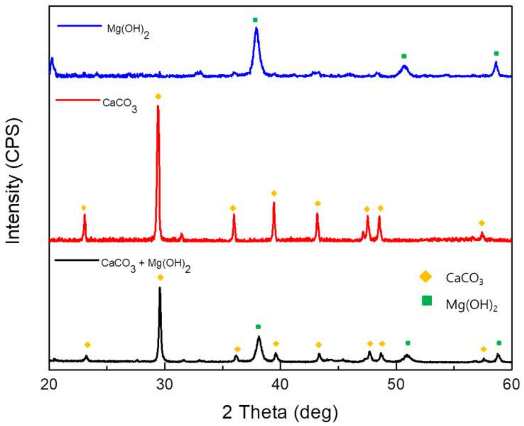
3.1. Formation of Calcareous Deposits

The potentiostatic tests were performed at −1.0 VSCE for 30 h to form three kinds of calcareous deposits on the carbon steel. Figure 2 shows the potentiostatic test results over the 30-h period. The current density decreased with time for all solution types. This can be explained by the electrochemical reactions on the surfaces of the cathodic site. When the specimens were negatively charged in the solution containing both Ca and Mg, the dissolved oxygens were converted into OH ions, leading to an increase in the pH on the surface. Because of the increasing number of OH ions, Mg ions reacted with them, forming an Mg(OH)2 deposition on the metal surface. In addition, the increase in OH ions affected the carbonate equilibrium at the metal surface. Thus, a CaCO3 layer was deposited on the metal surface. These processes can be described by the following reactions [21,22,23,24,25]:
O2 + 2H2O + 4e → 4OH
Mg2+ + 2OH → Mg(OH)2 (s)
OH + HCO3 → CO32 + H2O
Ca2+ + CO32− → CaCO3 (s)
These calcareous deposits decreased the O2 diffusion to the metal surface as a physical and electrical coating layer, and hindered the oxygen reduction reaction [23,26]. Therefore, the current density was decreased because of the formation of calcareous deposits on the metal surface, as shown in Figure 2. However, in the case of the solution with only Mg, the Mg(OH)2 layer was porous and gel-like rather than solid. It offered a relatively lower protective property at the surface of the metal compared with the other layers, and it did not significantly decrease the current inflow to the metal [27]. Therefore, the specimen that deposited only Mg(OH)2 had the highest current density. In contrast, the CaCO3 layer has the property of forming a solid and dense layer. Because the CaCO3 layer with these properties grew without any interference, the current density decreased rapidly to the lowest current density value measured in this study [28]. The specimen that deposited both CaCO3 and Mg(OH)2 had a current density higher than that of the specimen with only CaCO3, and a current density lower than that of the specimen with only Mg(OH)2. This is because the Mg(OH)2 hindered the growth of the CaCO3, meaning that the formed CaCO3 layer was thin and unstable [28,29].

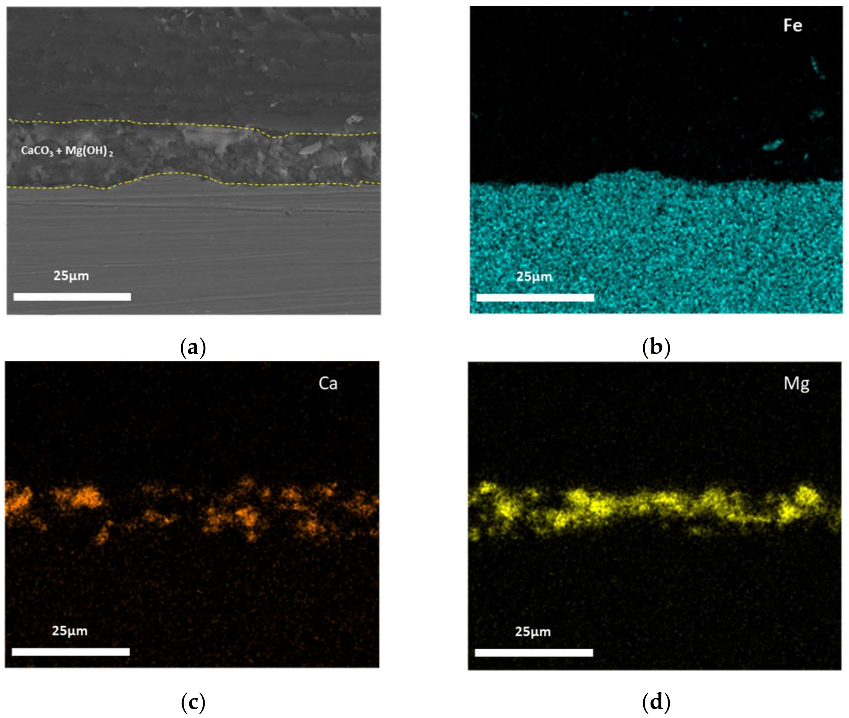
3.2. Surface Analysis

The cross-sectional SEM images and EDS mapping results of the calcareous deposits after the 30-h potentiostatic polarization tests are shown in Figure 3, Figure 4 and Figure 5. Figure 3 shows this information for the calcareous deposit based only on Mg, revealing a thin Mg(OH)2 layer deposited on the carbon steel. Figure 4 shows this information for the deposit based only on Ca, revealing a relatively thicker CaCO3 layer deposited on the carbon steel than the other deposit layers. Figure 5 shows the SEM image and EDS mapping results of the mixed CaCO3 and Mg(OH)2 deposit. This calcareous deposit layer included both Ca and Mg, and can therefore be regarded as a combined CaCO3 and Mg(OH)2 layer. In addition, it was confirmed that the Mg(OH)2, which hindered the growth of the CaCO3, resulted in a thinner CaCO3 layer compared with the specimen containing only CaCO3 [28,29].
Figure 6 shows the XRD patterns used to verify the three types of calcareous deposits on the surfaces of the specimens. It was confirmed that the calcareous deposit layer from the Mg(OH)2-added soil solution was Mg(OH)2. In addition, the calcareous deposit layer from the CaCO3-added soil solution was CaCO3. Finally, the calcareous deposit layer from the CaCO3 and Mg(OH)2-added soil solution consisted of CaCO3 and Mg(OH)2. When the calcareous deposition layer is formed in a solution to which CaCO3 and Mg(OH)2 are added, not only CaCO3 and Mg(OH)2 are formed, but (Ca,Mg)CO3 (JCPDS 43-0697), which is similar to the peaks of CaCO3 (JCPDS 05-0586), is also formed as the product. The width of the peaks of the calcareous deposit layer from the CaCO3 and Mg(OH)2-added soil solution are greater than that of the peaks in the other two patterns because of the overlapping XRD peaks of the (Ca,Mg)CO3.

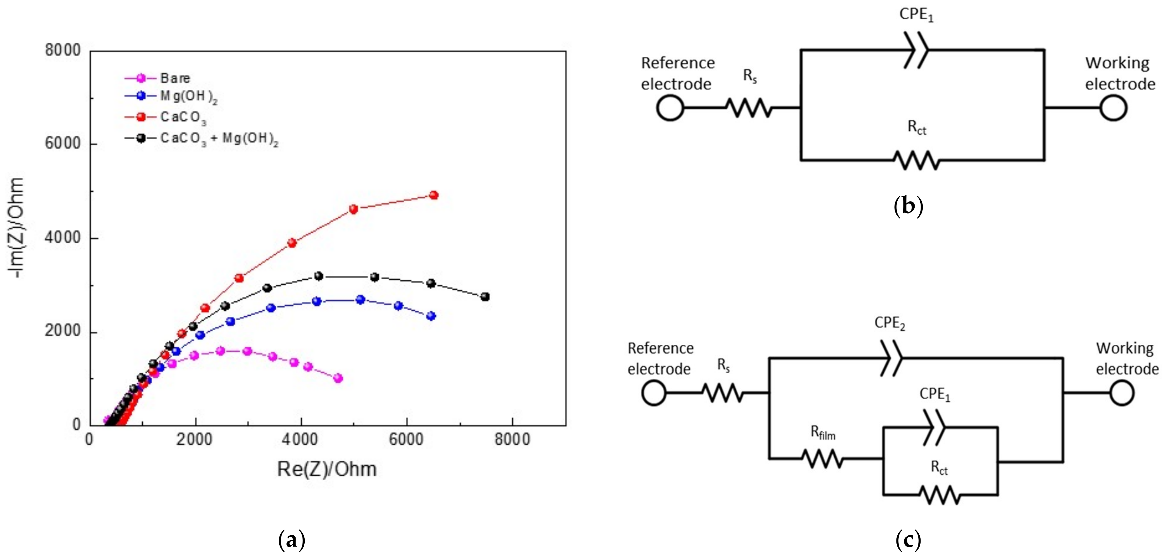
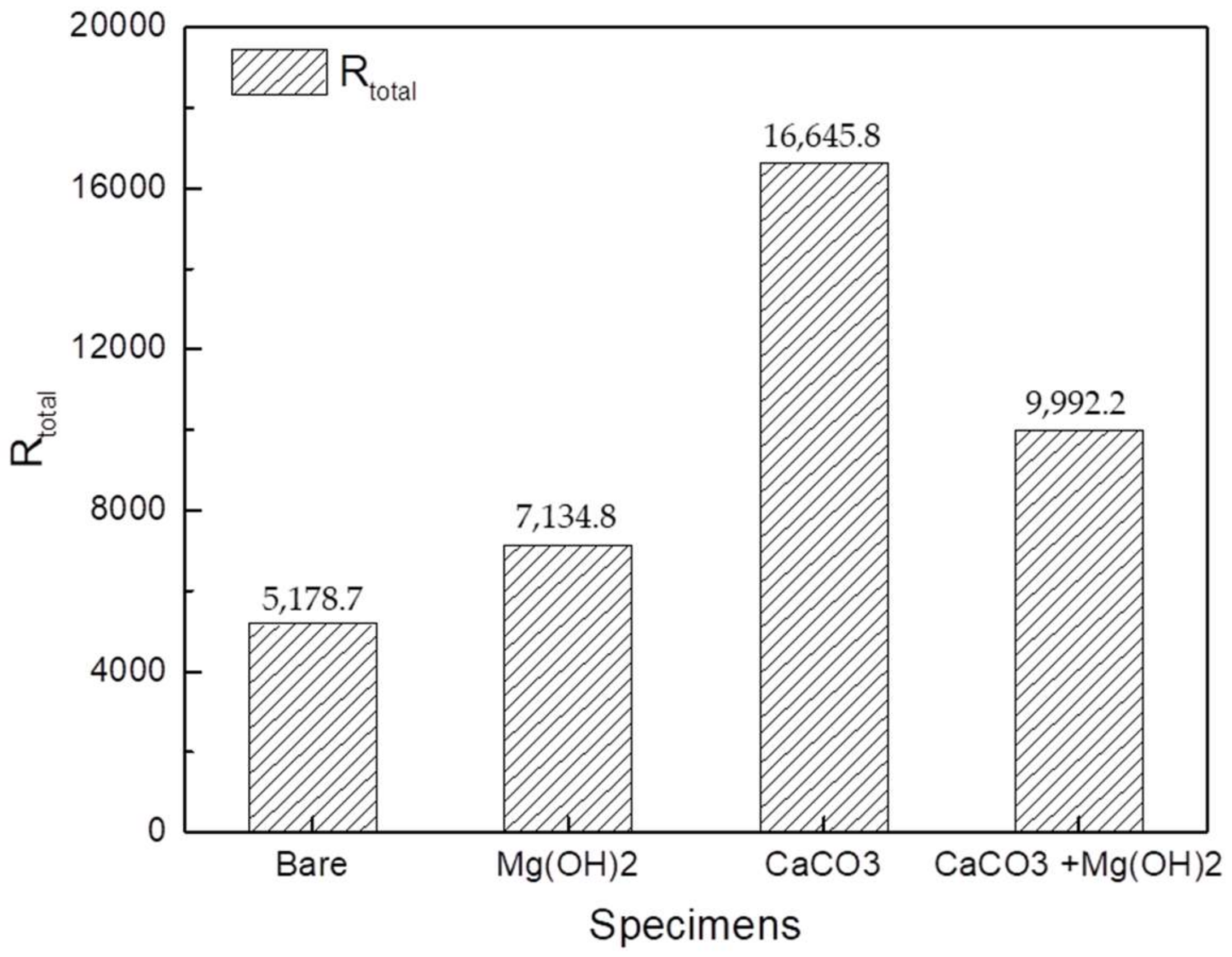
3.3. Electrochemical Impedance Spectroscopy

After the 30-h potentiostatic polarization tests, EIS measurements were performed. The Nyquist plots of the data from the electrodes giving different types of calcareous deposits are shown in Figure 7a. The Nyquist plots consist of a capacitive semicircle at a high frequency. Figure 7b presents the equivalent electrical circuit for bare steel, where Rs is the solution resistance, Rct is the charge transfer resistance, and CPE1 is the double-layer capacitance formed by the electrical double layer that exists at the interface between the electrolyte and electrode [26,30,31]. Figure 7c shows the equivalent electrical circuit that describes the formation of porous calcareous deposits on the surface of the steel. In Figure 7c, Rs is the solution resistance; CPE2 is the dielectric nature of the calcareous deposits, which is associated with the thickness of the calcareous deposit layer; Rfilm is the pore resistance; CPE1 is the capacitance generated by the metal dissolution reaction and by the electric double layer at the solution/metal interface; and Rct is the charge transfer resistance caused by the metal dissolution reaction [25]. Here, a CPE is used instead of a capacitor to compensate for the nonhomogeneity of the system frequency. The impedance of a CPE is described by the following equation:
ZCPE = A−1(jω)−n
where A−1 is the proportionality coefficient (with units, Ω−1 sn cm−2); ω is the angular frequency (rad s−1); j2 = −1 is an imaginary number; and n is an empirical exponent (0 ≤ n ≤ 1) that measures the deviation from the ideal capacitive behavior [32,33,34].
The results of the EIS fitting using the ZSimpWin software are shown in Table 3. The Rfilm values were the largest in the CaCO3 layer, followed by the CaCO3 and Mg(OH)2 mixed layer, and then the Mg(OH)2 layer. Similar to the results for the Rfilm value, CaCO3 had the largest Rct value, followed by the CaCO3 and Mg(OH)2 mixed layer, and then the Mg(OH)2 layer. These results indicate that the CaCO3 layer worked better as a protective layer than the others. At the same time, the CPE1 values tend to be the opposite of Rct. This is because the active area of metal dissolution decreases as the calcareous deposition becomes wider and thicker on the metal surface. The CPE2 values of the CaCO3 layer were higher than those of the other calcareous deposit layers, meaning that the CaCO3 layer was the thickest. This is in agreement with the SEM image results. Figure 8 shows the total resistance values of the bare steel and the three types of calcareous deposits. All specimens with calcareous deposits had a higher total resistance than the bare specimen, demonstrating that the calcareous deposits provided protection to the bare specimens.

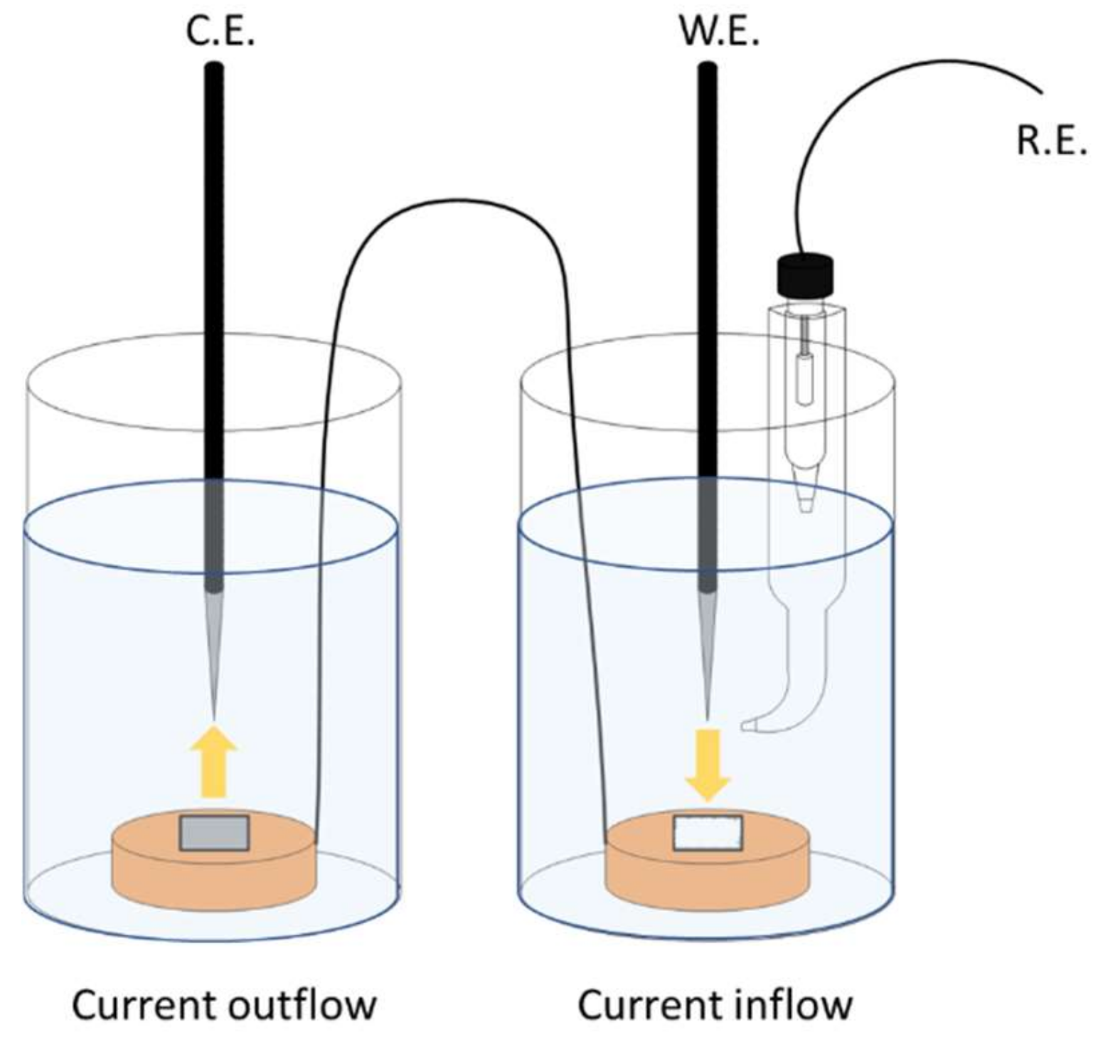
3.4. Corrosion Acceleration Test

A potentiostatic test was performed at 3.5 VSCE for 100 h to verify the stray current corrosion mitigation of the calcareous deposits [35]. Figure 9 shows the total electric charge at the current inflow area when 3.5 VSCE was applied for 100 h, along with the mass loss of the specimen at the current outflow area. The total electrical charge value was obtained using the following equation [14,36]:
Q = t i t f I   d t
Since the calcareous deposits decreased the inflow current, the total electric charge values of all specimens with a calcareous deposit were lower than that of the bare specimen. During the corrosion acceleration tests, a crack occurred in the unstable Mg(OH)2 layer. Therefore, the total electric charge of the specimen with the Mg(OH)2 layer is higher than those of the other specimens with calcareous deposits. In addition, the total electric charge of the specimen with the CaCO3 layer is lower than those of the other specimens, meaning that the CaCO3 layer was the most protective against inflow current. Figure 10 shows that the specimen on which CaCO3 is deposited receives the lowest inflow current and acts as a stable electrical barrier layer. This is because the CaCO3 layer grows in a solid and stable form, compared to the Mg(OH)2 deposition layer, and without the hindering of Mg(OH)2, it forms a thicker deposition layer than other layers [28,29]. Therefore, it acts as an electrical and physical barrier that blocks the external inflow current more efficiently than other layers. The total electric charge of the specimen with the CaCO3 and Mg(OH)2 mixed layer is higher than that of the specimen with the CaCO3 layer, and lower than that of the specimen with the Mg(OH)2 layer. Generally, more current flowing in means more current flowing out. Therefore, as current inflow increases, the areas where the current outflows become more susceptible to corrosion. As a result, among the specimens representing the current outflow area, the mass loss was the lowest in the specimen with the CaCO3 layer deposited. The mass reduction then increased in the following order, with respect to the deposit layer composition: CaCO3; the CaCO3 and Mg(OH)2 mixed layer; the Mg(OH)2 layer; and the bare specimen.

4. Conclusions

This study evaluated the stray current corrosion mitigation of calcareous deposits on carbon steel in a synthetic soil solution using the electrochemical tests, SEM, EDS, and XRD. On the basis of the experiments, the following conclusions can be drawn:
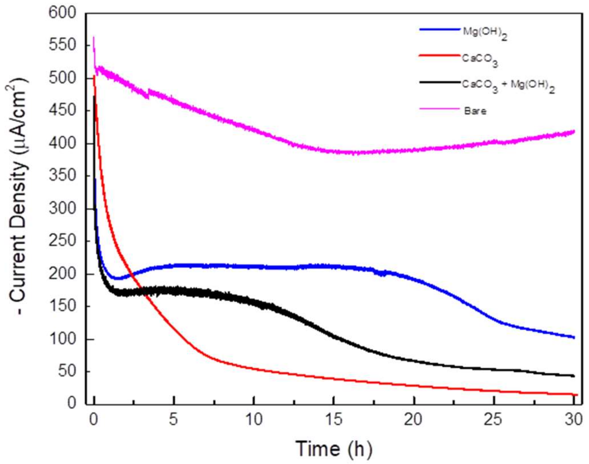
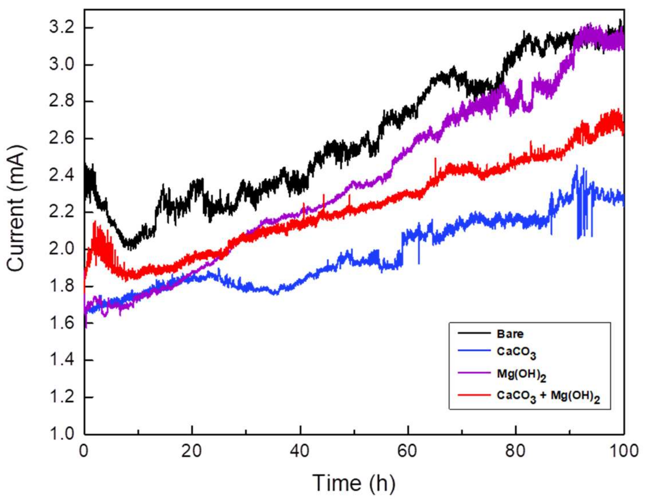
  • In the potentiostatic test, the current densities in all types of calcareous deposit layers decreased with the test time;
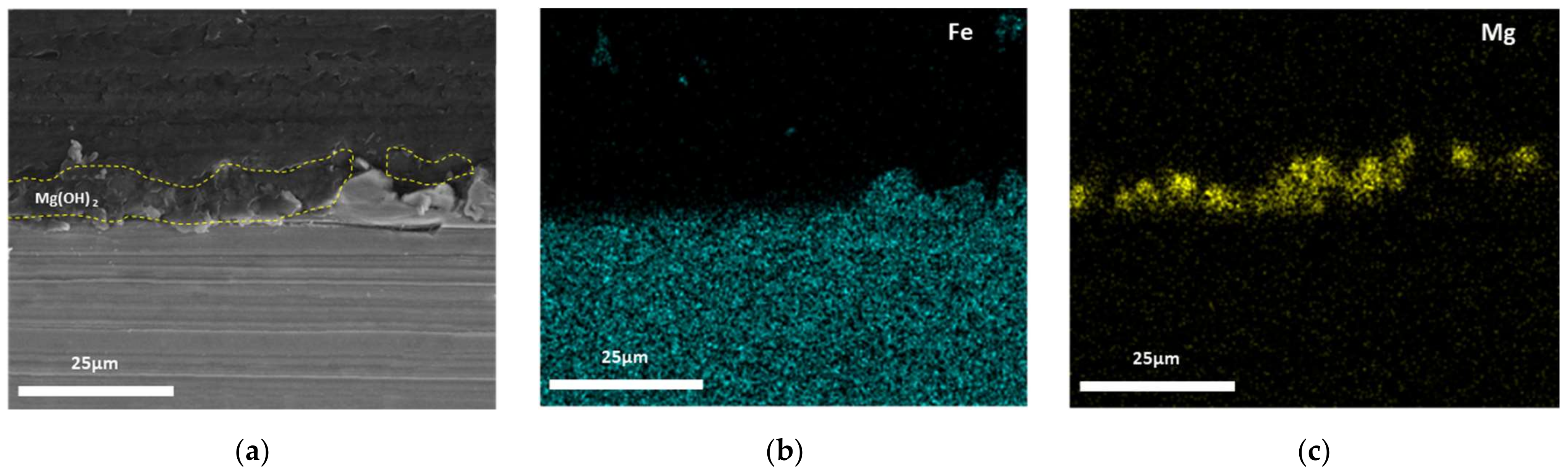
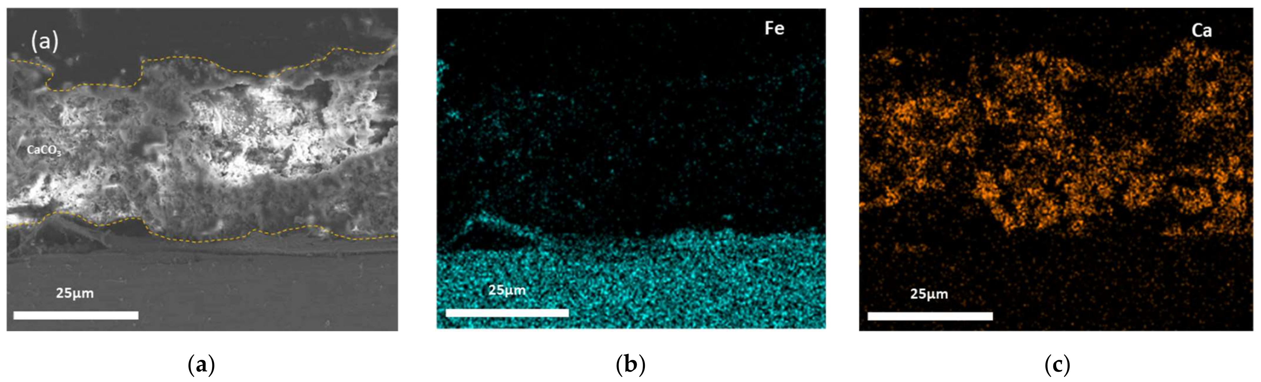
  • The specimen with the CaCO3 layer had the lowest current density. In the surface analysis, the specimen in the CaCO3 solution has the thickest layer compared to the Mg(OH)2 and mixed solutions;
  • In the EIS test, the specimen immersed in the CaCO3 solution had the highest Rfilm and Rct, indicating that the calcareous deposit of CaCO3 is the most protective layer;
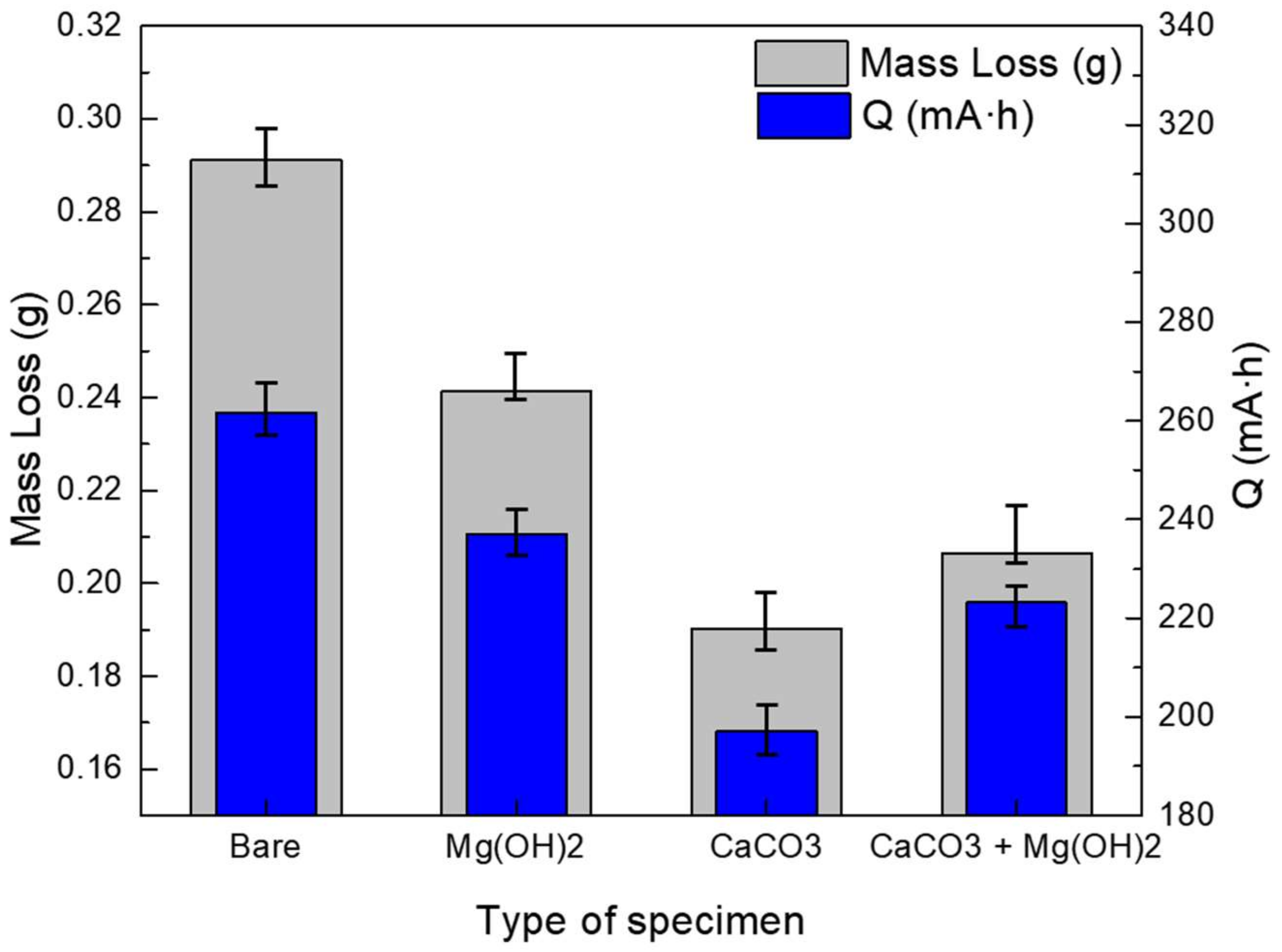
  • The potentiostatic acceleration test demonstrated that the CaCO3 layer had the lowest total electric charge among the specimens with calcareous deposits. In addition, the mass loss by the current outflow was the lowest in those with a CaCO3 layer.
Consequently, stray current corrosion can be effectively mitigated if CaCO3 powders are buried together with the pipelines and deposited when the soil solution and stray current are introduced to the pipelines.

Author Contributions

Conceptualization, S.-J.K.; methodology, S.-J.K.; validation, M.-S.H. and J.-G.K.; formal analysis, S.-J.K.; investigation, S.-J.K.; resources, M.-S.H.; data curation, S.-J.K. and M.-S.H.; writing—original draft preparation, S.-J.K.; writing—review and editing, S.-J.K. and M.-S.H.; visualization, S.-J.K.; supervision, J.-G.K.; project administration, J.-G.K.; funding acquisition, M.-S.H. and J.-G.K. All authors have read and agreed to the published version of the manuscript.

Funding

This work was supported by the National Research Foundation of Korea (NRF) grant, funded by the Korean Government (MEST) (No. NRF-2019R1A2B5B01070453).

Institutional Review Board Statement

Not applicable.

Informed Consent Statement

Not applicable.

Data Availability Statement

Not applicable.

Conflicts of Interest

The authors declare no conflict of interest.

References

  1. Chen, Z.; Koleva, D.; van Breugel, K. A review on stray current-induced steel corrosion in infrastructure. Corros. Rev. 2017, 35, 397–423. [Google Scholar] [CrossRef]
  2. Yoo, Y.H.; Nam, T.H.; Choi, Y.S.; Kim, J.G.; Chung, L. A galvanic sensor system for detecting the corrosion damage of the steel embedded in concrete structures: Laboratory tests to determine the cathodic protection and stray-current. Met. Mater. Int. 2011, 17, 623–629. [Google Scholar] [CrossRef]
  3. Guo, Y.B.; Liu, C.; Wang, D.G.; Liu, S.H. Effects of alternating current interference on corrosion of X60 pipeline steel. Pet. Sci. 2015, 12, 316–324. [Google Scholar] [CrossRef] [Green Version]
  4. Wang, X.; Wang, Z.; Chen, Y.; Song, X.; Yang, Y. Effect of a DC stray current on the corrosion of X80 pipeline steel and the cathodic disbondment behavior of the protective 3PE coating in 3.5% NaCl solution. Coatings 2019, 9, 29. [Google Scholar] [CrossRef] [Green Version]
  5. Chao, Y.; Gan, C.; Zili, L.; Yalei, Z.; Chengbin, Z. Study the influence of DC stray current on the corrosion of X65 steel using electrochemical method. Int. J. Electrochem. Sci. 2015, 10, 10223–10231. [Google Scholar]
  6. Riskin, J. Electrocorrosion and Protection of Metals: General Approach with Particular Consideration to Electrochemical Plants; Elsevier Science: Amsterdam, Netherlands, 2008. [Google Scholar]
  7. Bertolini, L.; Carsana, M.; Pedeferri, P. Corrosion behaviour of steel in concrete in the presence of stray current. Corros. Sci. 2007, 49, 1056–1068. [Google Scholar] [CrossRef]
  8. Chen, Z.; Qin, C.; Tang, J.; Zhou, Y. Experiment research of dynamic stray current interference on buried gas pipeline from urban rail transit. J. Nat. Gas Sci. Eng. 2013, 15, 76–81. [Google Scholar] [CrossRef]
  9. Richard, W.S.; David, D.; Carl, E.L., Jr. Stray Current Corrosion Due to Utility Cathodic Protection; Structural Engineering and Engineering Materials SM Report No. 45; University of Kansas Center for Research, Inc.: Lawrence, KS, USA, 1997; Chapter 2; pp. 10–17. [Google Scholar]
  10. Zhu, Q.; Cao, A.; Zaifend, W.; Song, J.; Shengli, C. Stray current corrosion in buried pipeline. Anti-Corros. Methods Mater. 2011, 58, 234–237. [Google Scholar] [CrossRef]
  11. Lin, Y.; Li, K.; Su, M.; Meng, Y. Research on stray current distribution of Metro based on Numerical Simulation. In Proceedings of the 2018 IEEE International Symposium on Electromagnetic Compatibility and 2018 IEEE Asia-Pacific Symposium on Electromagnetic Compatibility (EMC/APEMC), Suntec City, Singapore, 14–18 May 2018. [Google Scholar]
  12. Kim, Y.S.; Kim, J.G. Failure analysis of a thermally insulated pipeline in a district heating system. Eng. Fail. Anal. 2018, 83, 193–206. [Google Scholar] [CrossRef]
  13. Hong, M.S.; So, Y.S.; Kim, J.G. Optimization of cathodic protection design for pre-insulated pipeline in district heating system using computational simulation. Materials 2019, 12, 1761. [Google Scholar] [CrossRef] [PubMed] [Green Version]
  14. Tang, K. Stray current induced corrosion of steel fibre reinforced concrete. Cem. Concr. Res. 2017, 100, 445–456. [Google Scholar] [CrossRef] [Green Version]
  15. Szeliga, M.J. “Stray Current Corrosion”, in: Peabody’s Control of Pipeline Corrosion, 2nd ed.; NACE International: Houston, TX, USA, 2001; p. 211. [Google Scholar]
  16. Wang, C. Stray Current Distributing Model in the Subway System: A review and outlook. Int. J. Electrochem. Sci. 2018, 13, 1700–1727. [Google Scholar] [CrossRef]
  17. Du, G.; Wang, J.; Jiang, X.; Zhang, D.; Yang, L.; Hu, Y. Evaluation of Rail Potential and Stray Current with Dynamic Traction Networks in Multitrain Subway Systems. IEEE Trans. Transp. Electrif. 2020, 6, 784–796. [Google Scholar] [CrossRef]
  18. Ghanbari, E.; Lillard, R.S. The influence of CaCO3 scale formation on AC corrosion rates of pipeline steel under cathodic protection. Corrosion 2017, 74, 551–565. [Google Scholar] [CrossRef]
  19. Barchiche, C.; Deslouis, C.; Gil, O.; Refait, P.; Tribollet, B. Characterisation of calcareous deposits by electrochemical methods: Role of sulphates, calcium concentration and temperature. Electrochim. Acta 2004, 49, 2833–2839. [Google Scholar] [CrossRef]
  20. Ce, N.; Paul, S. The effect of temperature and local pH on calcareous deposit formation in damaged thermal spray aluminum (TSA) coatings and its implication on corrosion mitigation of offshore steel structures. Coatings 2017, 7, 52. [Google Scholar] [CrossRef] [Green Version]
  21. Devos, O.; Jakab, S.; Gabrielli, C.; Joiret, S.; Tribollet, B.; Picart, S. Nucleation-growth process of scale electrodeposition – influence of the magnesium ions. J. Cryst. Growth 2009, 311, 4334–4342. [Google Scholar] [CrossRef]
  22. Zhang, L.; Shen, H.-J.; Sun, J.-Y.; Sun, Y.-N.; Fang, Y.-C.; Cao, W.-H.; Xing, Y.-Y.; Lu, M.-X. Effect of calcareous deposits on hydrogen permeation in X80 steel under cathodic protection. Mater. Chem. Phys. 2018, 207, 123–129. [Google Scholar] [CrossRef]
  23. Hong, M.S.; Hwang, J.H.; Kim, J.H. Optimization of the cathodic protection design in consideration of the temperature variation for offshore structures. Corrosion 2018, 74, 123–133. [Google Scholar] [CrossRef]
  24. Yan, J.-F.; Nguyen, T.V.; White, R.E.; Griffin, R.B. Mathematical modeling of the formation of calcareous deposits on cathodically protected steel in seawater. J. Electrochem. Soc. 1993, 140, 733–742. [Google Scholar] [CrossRef]
  25. Deslouis, C.; Festy, D.; Gil, O.; Rius, G.; Touzain, S.; Tribollet, B. Characterization of calcareous deposits in artificial sea water by impedance techniques-I. Deposit of CaCO3 without Mg(OH)2. Electrochim. Acta 1998, 43, 1891–1901. [Google Scholar] [CrossRef]
  26. Li, C.J.; Du, M. The growth mechanism of calcareous deposits under various hydrostatic pressures during the cathodic protection of carbon steel in seawater. RSC Adv. 2017, 7, 28819–28825. [Google Scholar] [CrossRef] [Green Version]
  27. Deslouis, C.; Festy, D.; Gil, O.; Maillot, V.; Touzain, S.; Tribollet, B. Characterization of calcareous deposits in artificial sea water by impedances techniques: 2-deposit of Mg(OH)2 without CaCO3. Electrochim. Acta 2000, 45, 1837–1845. [Google Scholar] [CrossRef]
  28. Carré, C.; Zanibellato, A.; Jeannin, M.; Sabot, R.; Gunkel-Grillon, P.; Serres, A. Electrochemical calcareous deposition in seawater. A review. Environ. Chem. Lett. 2020, 18, 1193–1208. [Google Scholar] [CrossRef]
  29. Barchiche, C.; Deslouis, C.; Festy, D.; Gil, O.; Refait, P.; Touzain, S.; Tribollet, B. Characterization of calcareous deposits in artificial seawater by impedance techniques 3- Deposit of of CaCO3 in the presence of Mg(OH)2. Electrochim. Acta 2003, 48, 1645–1654. [Google Scholar] [CrossRef]
  30. Kim, Y.-S.; Kim, S.-H.; Kim, J.-G. Effect of 1, 2, 3-benzotriazole on the corrosion properties of 316L stainless steel in synthetic tap water. Met. Mater. Int. 2015, 21, 1013–1022. [Google Scholar] [CrossRef]
  31. An, J.-H.; Lee, J.; Kim, Y.-S.; Kim, W.-C.; Kim, J.-G. Effects of Post Weld Heat Treatment on Mechanical and Electrochemical Properties of Welded Carbon Steel Pipe. Met. Mater. Int. 2018, 25, 304–312. [Google Scholar] [CrossRef]
  32. Zhang, P.Q.; Wu, J.X.; Zhang, Q.; Lu, X.Y.; Wang, K. Pitting mechanism for passive 304 stainless steel in sulphuric acid media containing chloride ions. Corros. Sci. 1993, 34, 1343–1354. [Google Scholar] [CrossRef]
  33. Lopez, D.A.; Simison, S.N.; De Sanchez, S.R. The influence of steel microstructure on CO2 corrosion. EIS studies on the inhibition efficiency of benzimidazole. Electrochim. Acta 2003, 48, 845–854. [Google Scholar] [CrossRef]
  34. Lee, D.Y.; Kim, W.C.; Kim, J.G. Effect of nitrite concentration on the corrosion behaviour of carbon steel pipelines in synthetic tap water. Corros. Sci. 2012, 64, 105–114. [Google Scholar] [CrossRef]
  35. Hong, M.S.; So, Y.S.; Lim, J.M.; Kim, J.G. Evaluation of internal corrosion property in district heating pipeline using fracture mechanics and electrochemical acceleration kinetics. J. Ind. Eng. Chem. 2021, 94, 253–263. [Google Scholar] [CrossRef]
  36. Silva, J.C.D.E.; Panicali, A.R.; Barbosa, C.F.; Caetano, C.E.F.; Paulino, J.O.S. Electric charge flow in linear circuits. Electr. Power Syst. Res. 2019, 170, 57–63. [Google Scholar] [CrossRef]
Figure 1. Schematic of stray current simulation cell.
Materials 14 07905 g001
Figure 2. Current density vs. time curves during potentiostatic test (applied voltage: −1.0 VSCE; solutions: synthetic soil solution with Mg(OH)2 CaCO3 and Mg(OH)2, CaCO3; testing time: 30 h).
Materials 14 07905 g002
Figure 3. The cross-sectional SEM images and EDS mapping results of Mg(OH)2: (a) cross-sectional image; (b) Fe (EDS mapping); and (c) Mg (EDS mapping).
Materials 14 07905 g003
Figure 4. The cross-sectional SEM images and EDS mapping results of CaCO3: (a) cross-sectional image; (b) Fe (EDS mapping); and (c) Ca (EDS mapping).
Materials 14 07905 g004
Figure 5. The cross-sectional SEM images and EDS mapping results of CaCO3 + Mg(OH)2: (a) cross-sectional image; (b) Fe (EDS mapping); (c) Ca (EDS mapping); and (d) Mg (EDS mapping).
Materials 14 07905 g005
Figure 6. XRD results for the 3 types of calcareous deposits after 30 h of potentiostatic polarization.
Materials 14 07905 g006
Figure 7. (a) Result of EIS test according to the types of calcareous deposits. (b) Equivalent circuit diagram of bare carbon steel. (c) Equivalent circuit diagram of carbon steel covered by calcareous deposits.
Materials 14 07905 g007
Figure 8. Comparison of total resistance on the bare and 3 types of calcareous deposited specimens.
Materials 14 07905 g008
Figure 9. Mass losses of corrosion specimen and quantities of inflow current after potentiostatic acceleration test.
Materials 14 07905 g009
Figure 10. Current vs. time curves during potentiostatic test (applied voltage: 3.5 VSCE; solutions: synthetic soil solution; testing time: 100 h).
Materials 14 07905 g010
Table 1. Chemical composition of SPW 400 (wt.%).
FeCPSSiMn
Bal0.130 max.0.018 max.0.070 max.0.240 max.0.560 max.
Table 2. Chemical composition of synthetic soil solution (ppm).
CaCl2MgSO4 7H2ONaHCO3H2SO4HNO3
133.259.0208.048.021.8
Table 3. The results of the EIS fitting using the circuit.
Type of
Deposit
RsCPE1RfilmCPE2Rct
(Ω·cm2)CPEY0 (0 < n < 1)(Ω·cm2)CPEY0 (0 < n < 1)(Ω·cm2)
Bare393.71.912 × 10−40.7527---4785
Mg(OH)2511.32.955 × 10−40.8693523.53.893 × 10−40.79536100
CaCO3568.25.955 × 10−40.7615865.91.702 × 10−40.723115,210
CaCO3 + Mg(OH)2375.92.923 × 10−40.7533643.41.795 × 10−40.79598872
Publisher’s Note: MDPI stays neutral with regard to jurisdictional claims in published maps and institutional affiliations.

