
Experimental and Simulation Research on the Preparation of Carbon Nano-Materials by Chemical Vapor Deposition

 , and
, and
Abstract
:1. Introduction
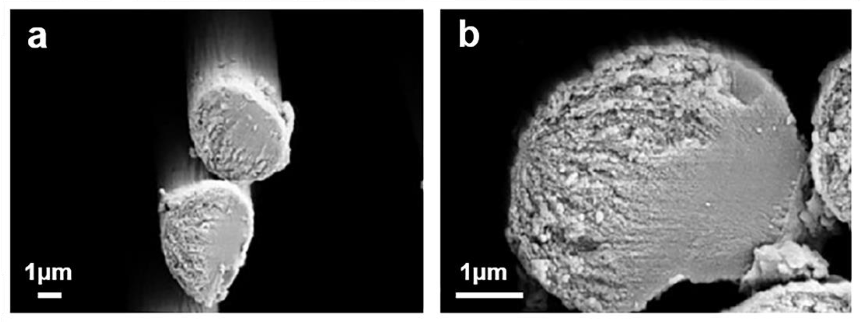
1.1. Carbon Fibers
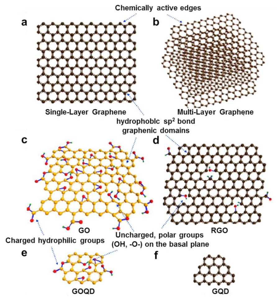
1.2. Graphene
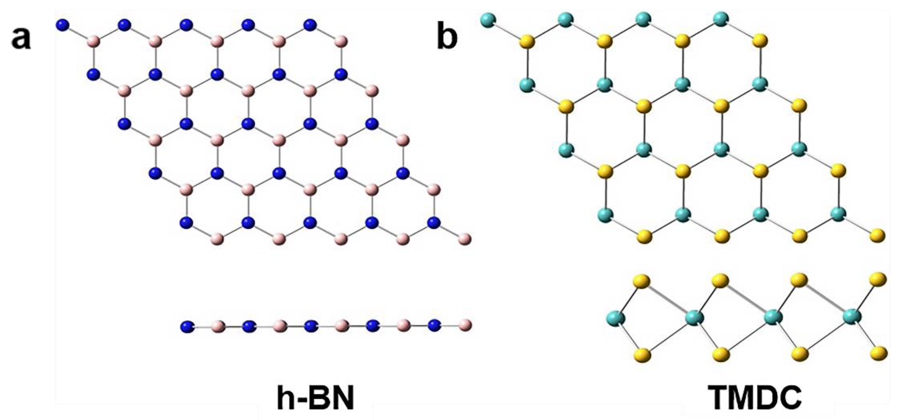
1.3. Graphene-like Materials
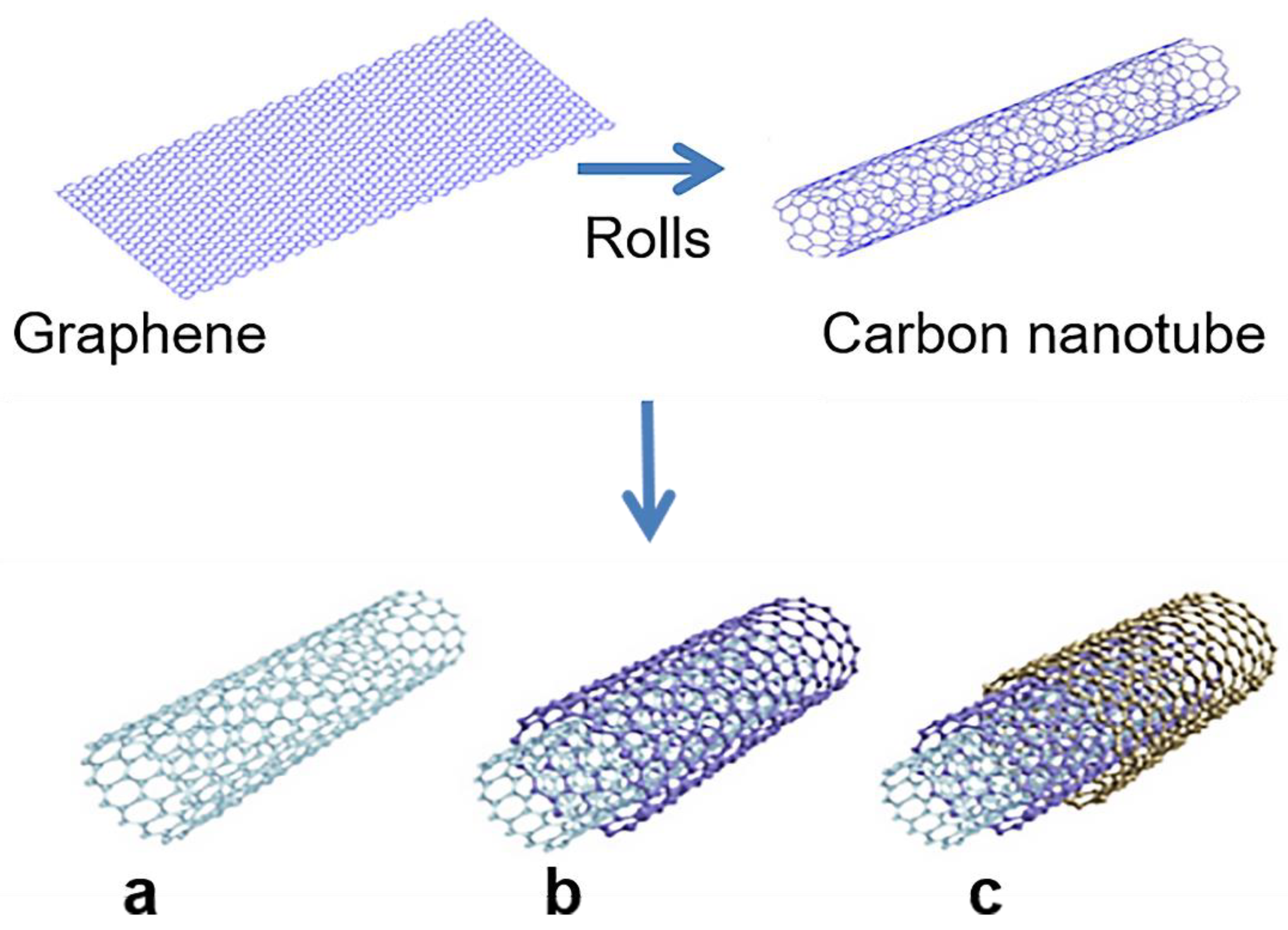
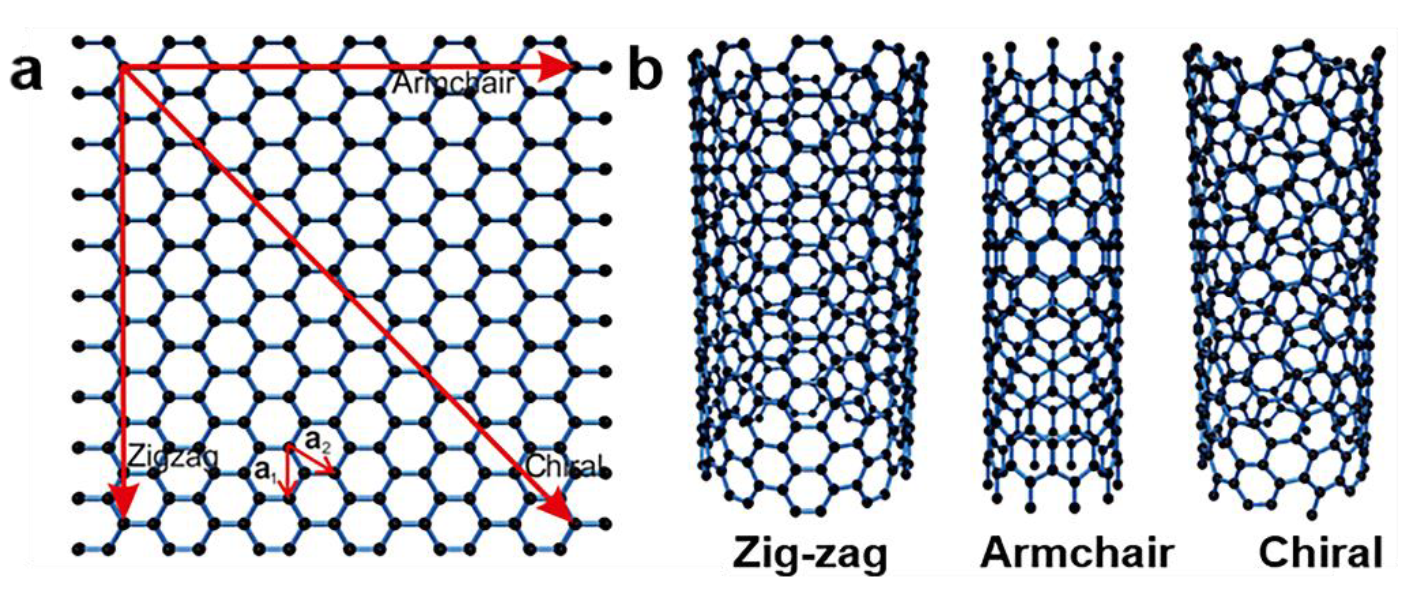
1.4. Carbon Nanotubes
2. Structure and Properties
2.1. Carbon Fibers
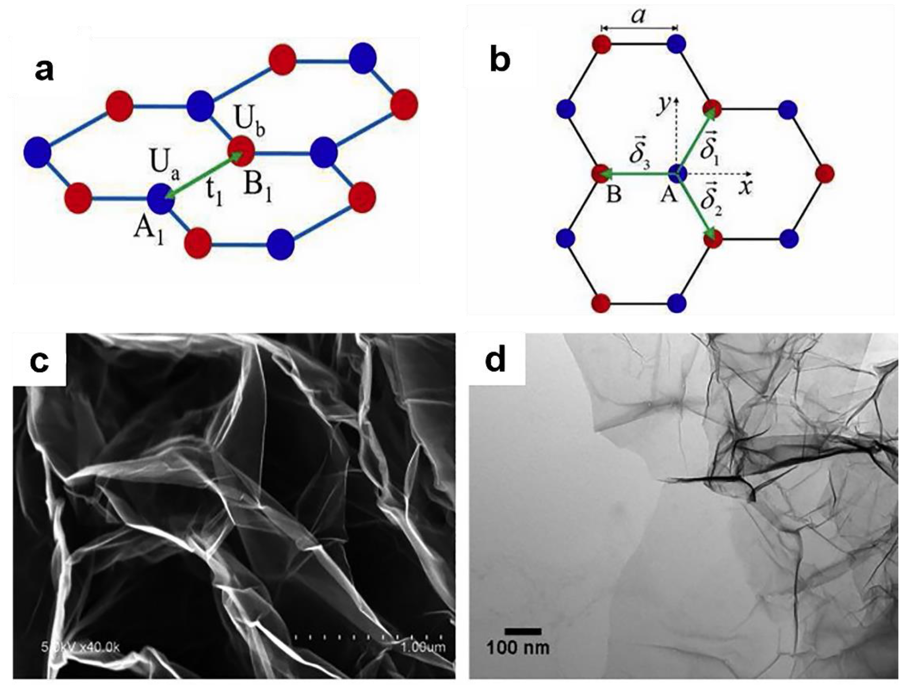
2.2. Graphene
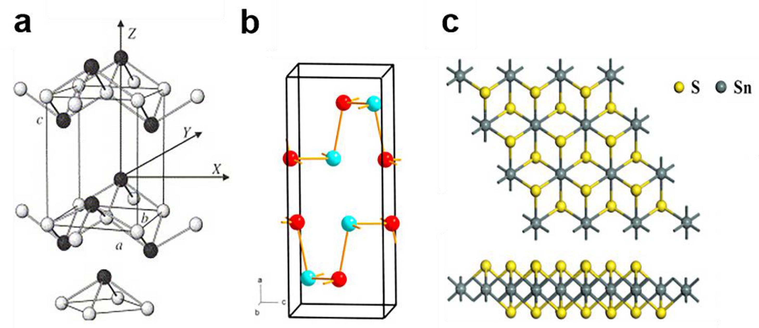
2.3. Graphene-like Materials
2.4. Carbon Nanotubes
3. Preparation of Carbon Materials
3.1. Carbon Fibers
3.2. Graphene
3.3. Graphene-like Materials
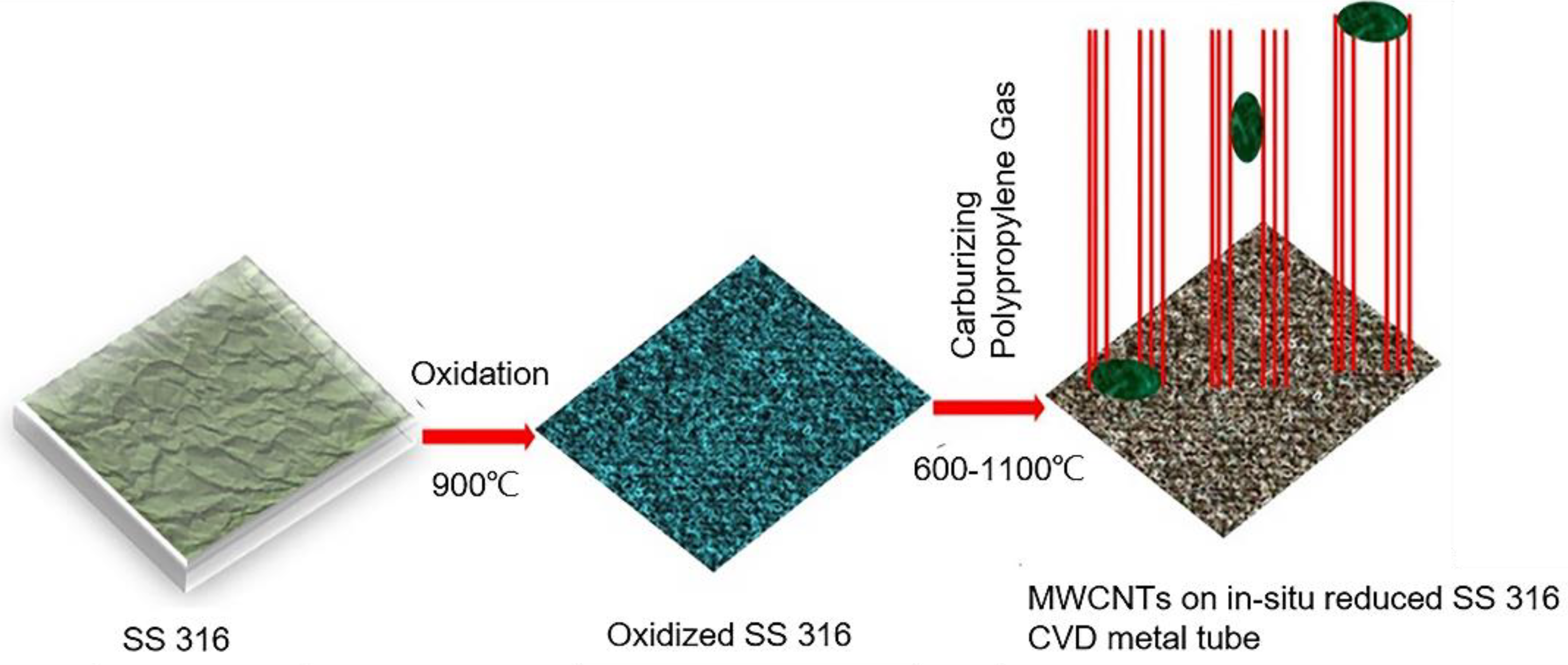
3.4. Carbon Nanotubes
3.4.1. Catalyst and Support Material
3.4.2. Carbon Precursor
3.4.3. Depositional Condition
4. Simulation of Synthesis Process of Carbon Materials Prepared by CVD
4.1. Simulation of Synthesis Process of Carbon Fibers Prepared by CVD
4.2. Simulation of Synthesis Process of Graphene Prepared by CVD
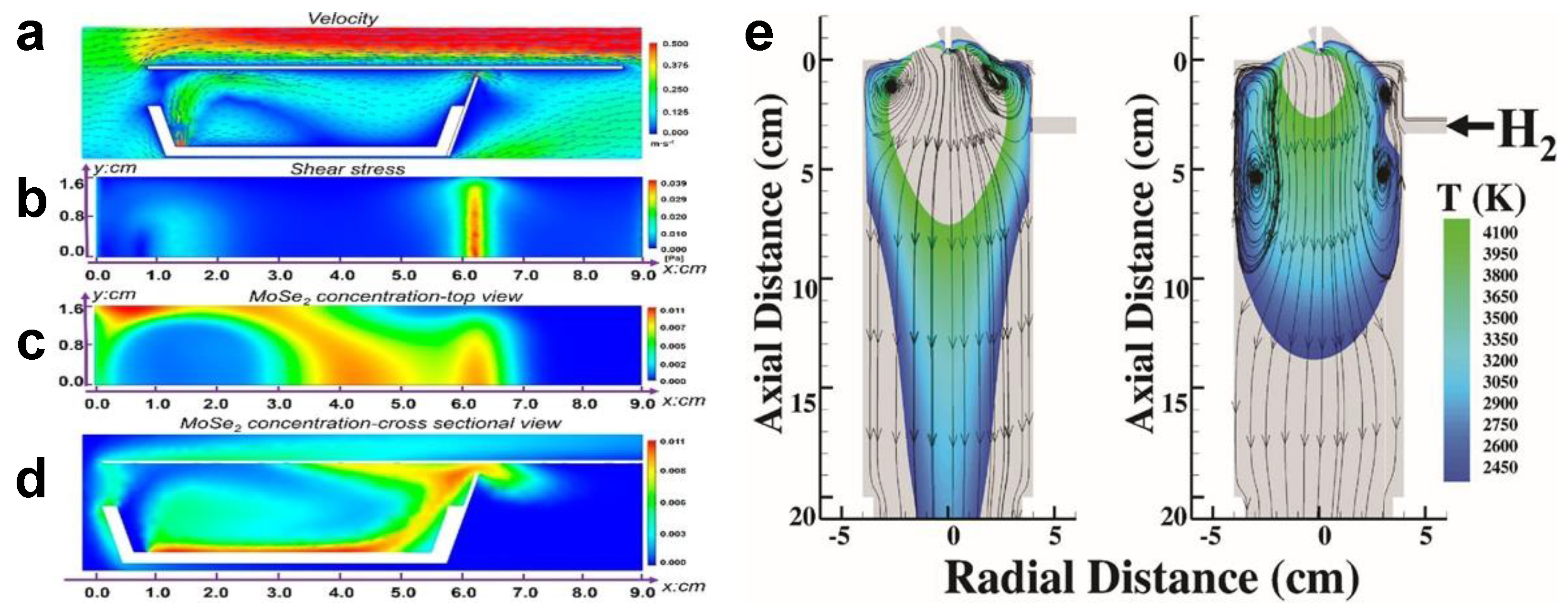
4.3. Simulation of Synthesis Process of Graphene-like Materials Prepared by CVD
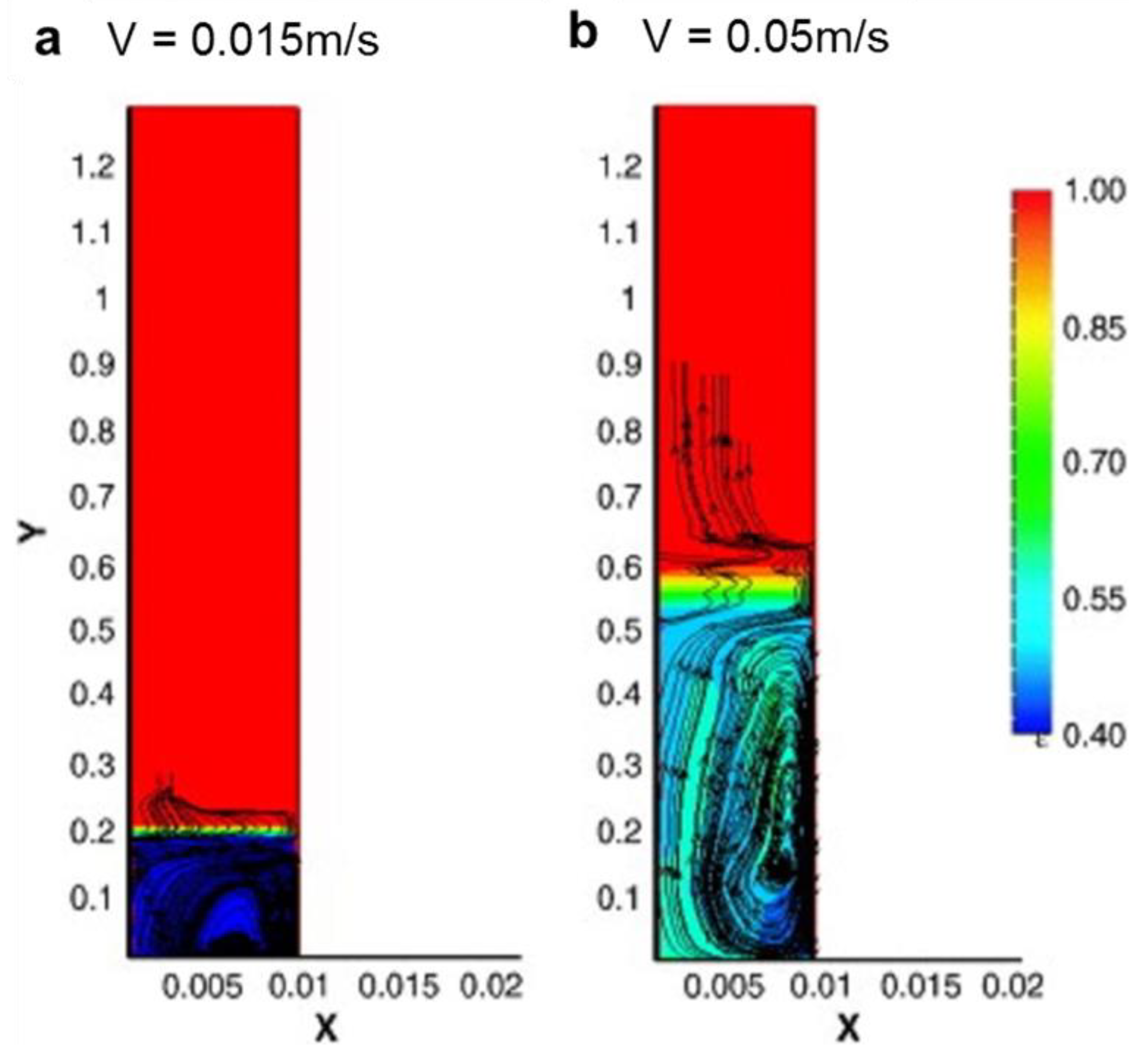
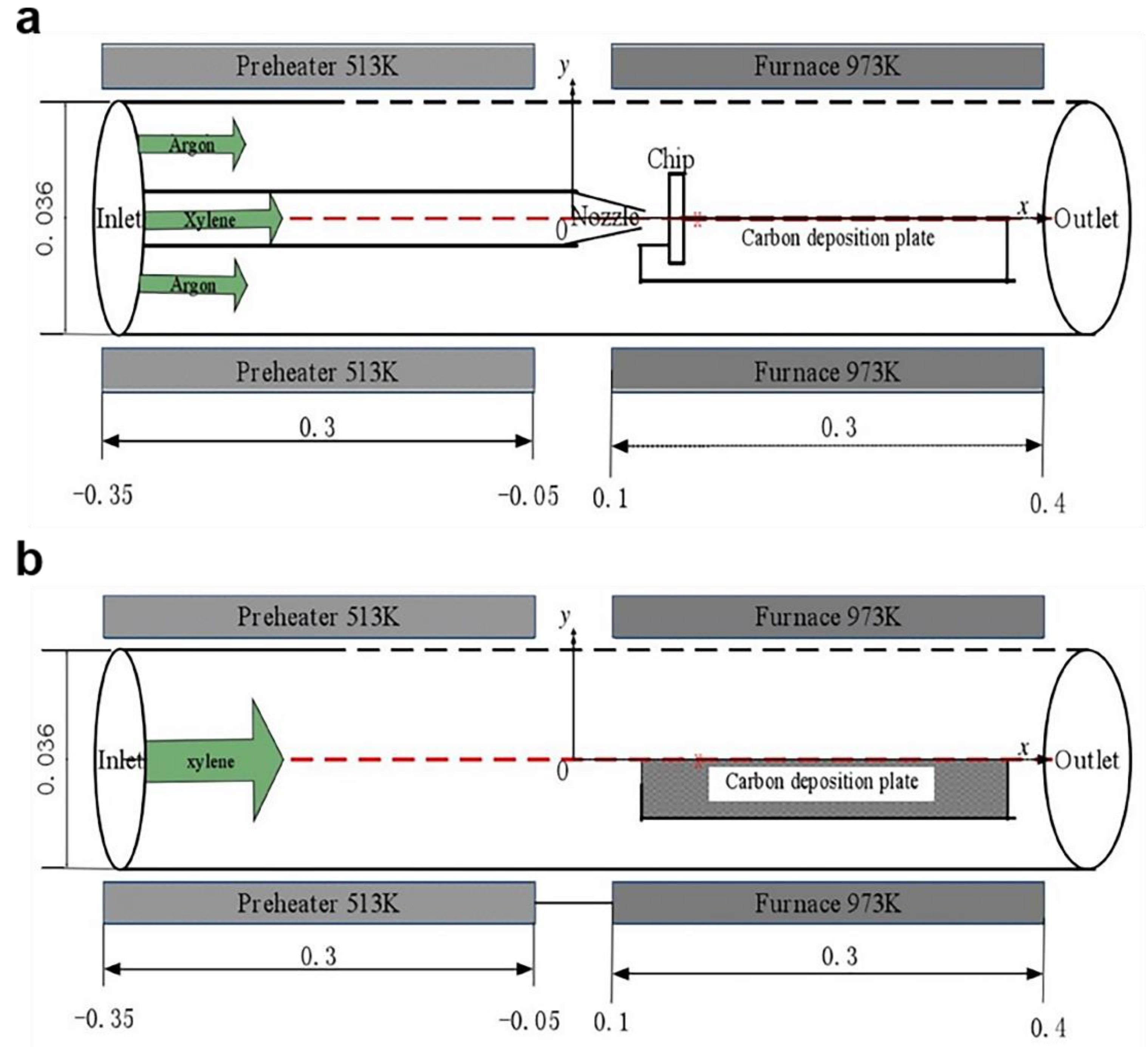
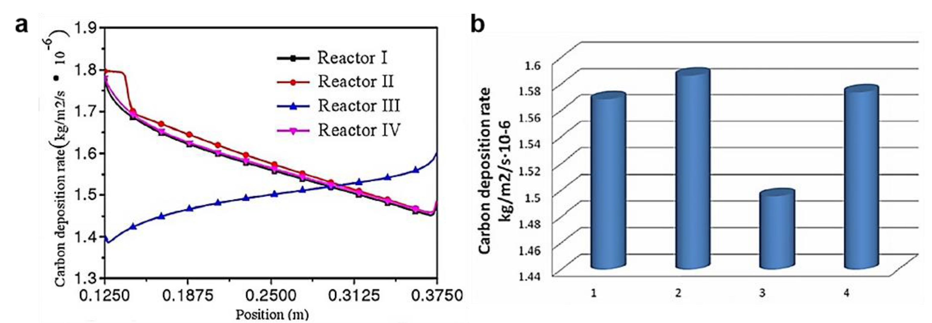
4.4. Simulation of Synthesis Process of Carbon Nanotubes Prepared by CVD
5. Summary and Future Directions
- The structural defects or doping of materials will have a certain impact on the properties of materials. The structure can be adjusted through the selection of preparation methods and the adjustment of process conditions to improve or inhibit some properties.
- In addition to the selection of conventional precursors, substrate materials and catalysts, the reaction temperature, time, pressure, and atmosphere have an impact on the growth quality, yield, and growth size of the materials. Only by grasping the choice of precursor and other materials and controlling the process conditions can we obtain higher quality and high performance carbon materials.
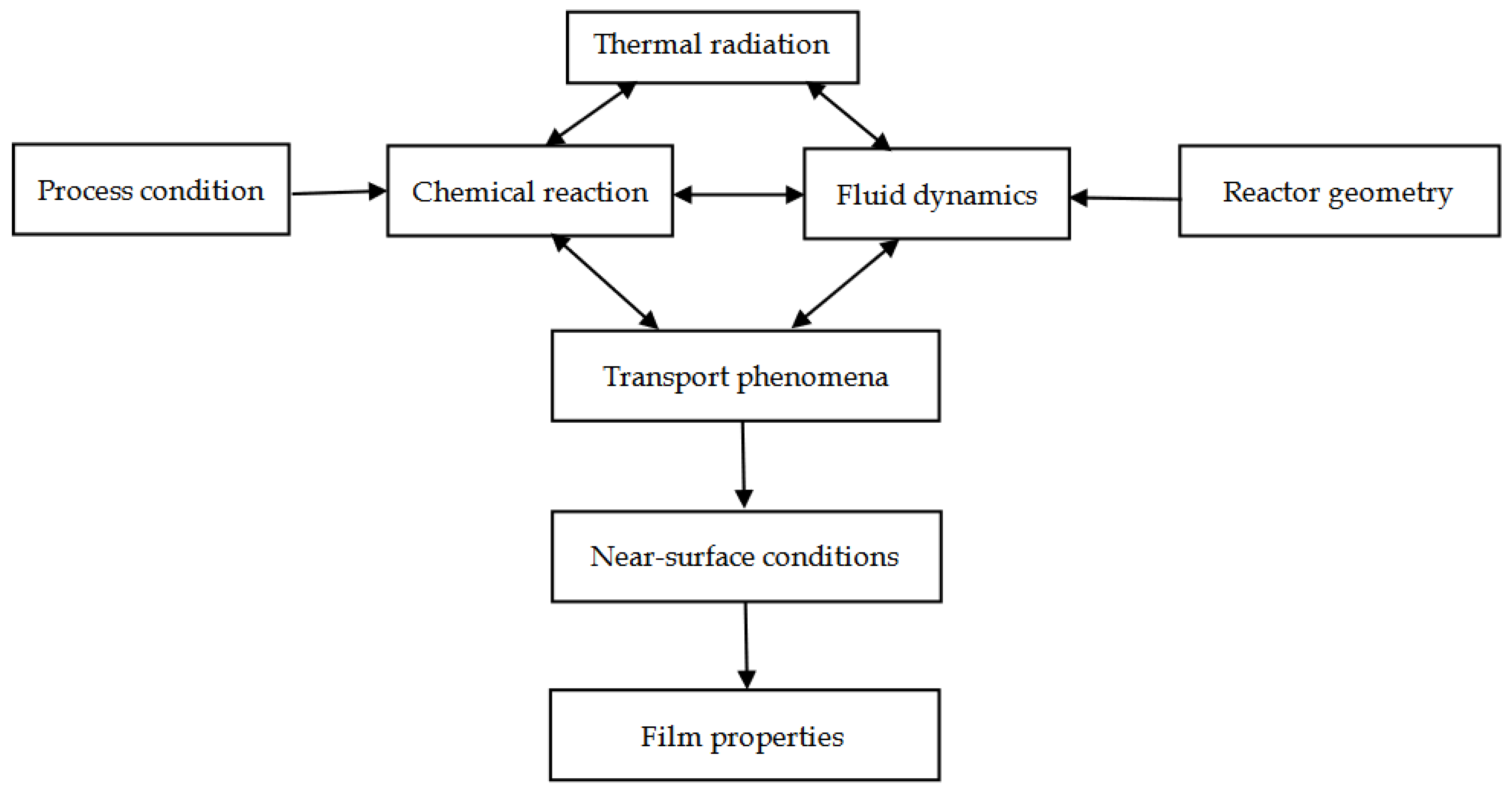
- Numerical simulation and analysis can provide valuable information for the complex physical and chemical changes in a chemical vapor deposition reactor. In the process of computational fluid dynamics simulation, the reaction parameters and reactor design can be optimized, and the temperature and velocity distribution of the reaction system can be simulated. Through the combination of simulation calculation and experiment, the improvement of production efficiency and production scale can be obtained.
Author Contributions
Funding
Institutional Review Board Statement
Informed Consent Statement
Data Availability Statement
Conflicts of Interest
References
- Wang, G.; Yu, M.; Feng, X. Carbon materials for ion-intercalation involved rechargeable battery technologies. Chem. Soc. Rev. 2021, 50, 2388–2443. [Google Scholar] [CrossRef]
- Fitzer, E. Pan-based carbon fibers—present state and trend of the technology from the viewpoint of possibilities and limits to influence and to control the fiber properties by the process parameters. Carbon 1989, 27, 621–645. [Google Scholar] [CrossRef]
- Edie, D. The effect of processing on the structure and properties of carbon fibers. Carbon 1998, 36, 345–362. [Google Scholar] [CrossRef]
- Huang, X. Fabrication and Properties of Carbon Fibers. Materials 2009, 2, 2369–2403. [Google Scholar] [CrossRef]
- Liu, Y.; Kumar, S. Recent Progress in Fabrication, Structure, and Properties of Carbon Fibers. Polym. Rev. 2012, 52, 234–258. [Google Scholar] [CrossRef]
- Li, W.; Long, D.; Miyawaki, J.; Qiao, W.; Ling, L.; Mochida, I.; Yoon, S.-H. Structural features of polyacrylonitrile-based carbon fibers. J. Mater. Sci. 2011, 47, 919–928. [Google Scholar] [CrossRef]
- Meek, N.; Penumadu, D. Nonlinear elastic response of pan based carbon fiber to tensile loading and relations to microstructure. Carbon 2021, 178, 133–143. [Google Scholar] [CrossRef]
- Novoselov, K.S.; Geim, A.K.; Morozov, S.V.; Jiang, D.; Zhang, Y.; Dubonos, S.V.; Grigorieva, I.V.; Firsov, A.A. Electric Field Effect in Atomically Thin Carbon Films. Science 2004, 306, 666–669. [Google Scholar] [CrossRef] [Green Version]
- Novoselov, K.S.; Fal′ko, V.I.; Colombo, L.; Gellert, P.R.; Schwab, M.G.; Kim, K. A roadmap for graphene. Nature 2012, 490, 192–200. [Google Scholar] [CrossRef]
- Peigney, A.; Laurent, C.; Flahaut, E.; Bacsa, R.; Rousset, A. Specific surface area of carbon nanotubes and bundles of carbon nanotubes. Carbon 2001, 39, 507–514. [Google Scholar] [CrossRef] [Green Version]
- Gadipelli, S.; Guo, Z.X. Graphene-based materials: Synthesis and gas sorption, storage and separation. Prog. Mater. Sci. 2015, 69, 1–60. [Google Scholar] [CrossRef] [Green Version]
- Cao, Y.; Fatemi, V.; Fang, S.; Watanabe, K.; Taniguchi, T.; Kaxiras, E.; Jarillo-Herrero, P. Unconventional superconductivity in magic-angle graphene superlattices. Nature 2018, 556, 43–50. [Google Scholar] [CrossRef]
- Kumar, N.; Salehiyan, R.; Chauke, V.; Botlhoko, O.J.; Setshedi, K.; Scriba, M.; Masukume, M.; Ray, S.S. Top-down synthesis of graphene: A comprehensive review. FlatChem 2021, 27, 100224. [Google Scholar] [CrossRef]
- Alam Bhuyan, S.; Uddin, N.; Islam, M.; Alam Bipasha, F.; Hossain, S.S. Synthesis of graphene. Int. Nano Lett. 2016, 6, 65–83. [Google Scholar] [CrossRef] [Green Version]
- Geim, A.K.; Novoselov, K. The rise of graphene. Nat. Mater. 2007, 6, 183–191. [Google Scholar] [CrossRef]
- Mao, H.Y.; Laurent, S.; Chen, W.; Akhavan, O.; Imani, M.; Ashkarran, A.A.; Mahmoudi, M. Graphene: Promises, Facts, Opportunities, and Challenges in Nanomedicine. Chem. Rev. 2013, 113, 3407–3424. [Google Scholar] [CrossRef]
- Zheng, X.T.; Ananthanarayanan, A.; Luo, K.Q.; Chen, P. Glowing Graphene Quantum Dots and Carbon Dots: Properties, Syntheses, and Biological Applications. Small 2015, 11, 1620–1636. [Google Scholar] [CrossRef]
- Peng, J.; Gao, W.; Gupta, B.K.; Liu, Z.; Romero-Aburto, R.; Ge, L.; Song, L.; Alemany, L.B.; Zhan, X.; Gao, G.; et al. Graphene Quantum Dots Derived from Carbon Fibers. Nano Lett. 2012, 12, 844–849. [Google Scholar] [CrossRef]
- Cheng, C.; Li, S.; Thomas, A.; Kotov, N.A.; Haag, R. Functional Graphene Nanomaterials Based Architectures: Biointeractions, Fabrications, and Emerging Biological Applications. Chem. Rev. 2017, 117, 1826–1914. [Google Scholar] [CrossRef]
- Wilson, J.A.; Yoffe, A.D. The transition metal dichalcogenides discussion and interpretation of the observed optical, electrical and structural properties. Adv. Phys. 2006, 18, 193. [Google Scholar] [CrossRef]
- Osada, M.; Sasaki, T. Two-Dimensional Dielectric Nanosheets: Novel Nanoelectronics from Nanocrystal Building Blocks. Adv. Mater. 2012, 24, 210. [Google Scholar] [CrossRef]
- Hozoi, L.; Siurakshina, L.; Fulde, P.; Brink, J.V.D. Ab Initio determination of Cu 3d orbital energies in layered copper oxides. Sci. Rep. 2011, 1, 65. [Google Scholar] [CrossRef]
- Golberg, D.; Bando, Y.; Huang, Y.; Terao, T.; Mitome, M.; Tang, C.; Zhi, C. Boron Nitride Nanotubes and Nanosheets. ACS Nano 2010, 4, 2979. [Google Scholar] [CrossRef]
- Zhang, H.; Liu, C.-X.; Qi, X.-L.; Dai, X.; Fang, Z.; Zhang, S.-C. Topological insulators in Bi2Se3, Bi2Te3 and Sb2Te3 with a single Dirac cone on the surface. Nat. Phys. 2009, 5, 438–442. [Google Scholar] [CrossRef]
- Tang, H.; Liang, D.; Qiu, R.L.J.; Gao, X.P.A. Two-Dimensional Transport-Induced Linear Magneto-Resistance in Topological Insulator Bi2Se3 Nanoribbons. ACS Nano 2011, 5, 7510–7516. [Google Scholar] [CrossRef] [Green Version]
- Dean, C.R.; Young, A.; Meric, I.; Lee, C.; Wang, L.; Sorgenfrei, S.; Watanabe, K.; Taniguchi, T.; Kim, P.; Shepard, K.L.; et al. Boron nitride substrates for high-quality graphene electronics. Nat. Nanotechnol. 2010, 5, 722–726. [Google Scholar] [CrossRef]
- Radisavljevic, B.; Whitwick, M.B.; Kis, A. Integrated Circuits and Logic Operations Based on Single-Layer MoS. ACS Nano 2011, 5, 9934–9938. [Google Scholar] [CrossRef]
- Mak, K.F.; Lee, C.; Hone, J.; Shan, J.; Heinz, T.F. Atomically ThinMoS2: A New Direct-Gap Semiconductor. Phys. Rev. Lett. 2010, 105, 136805. [Google Scholar] [CrossRef] [Green Version]
- Rokuta, E.; Hasegawa, Y.; Suzuki, K.; Gamou, Y.; Oshima, C.; Nagashima, A. Phonon Dispersion of an Epitaxial Monolayer Film of Hexagonal Boron Nitride on Ni(111). Phys. Rev. Lett. 1997, 79, 4609–4612. [Google Scholar] [CrossRef]
- Radisavljevic, B.; Radenovic, A.; Brivio, J.; Giacometti, V.; Kis, A. Single-layer MoS2 transistors. Nat. Nanotechnol. 2011, 6, 147–150. [Google Scholar] [CrossRef]
- Pawar, R.; Sangolkar, A.A. Density functional theory studies on h-BN–transition metal dichalcogenide heterostructures (TMDCs) and TMDC-h-BN-TMDC (sandwich heterostructures). Comput. Theor. Chem. 2021, 1204, 113417. [Google Scholar] [CrossRef]
- Pan, H.; Yin, X.; Xue, J.; Cheng, L.; Zhang, L. The microstructures, growth mechanisms and properties of carbon nanowires and nanotubes fabricated at different CVD temperatures. Diam. Relat. Mater. 2017, 72, 77–86. [Google Scholar] [CrossRef]
- Zhang, R.; Zhang, Y.; Wei, F. Horizontally aligned carbon nanotube arrays: Growth mechanism, controlled synthesis, characterization, properties and applications. Chem. Soc. Rev. 2017, 46, 3661–3715. [Google Scholar] [CrossRef]
- Oberlin, A.; Endo, M.; Koyama, T. Filamentous growth of carbon through benzene decomposition. J. Cryst. Growth 1976, 32, 335–349. [Google Scholar] [CrossRef]
- Iijima, S.; Ichihashi, T. Single-shell carbon nanotubes of 1-nm diameter. Nature 1993, 363, 603–605. [Google Scholar] [CrossRef]
- Bocko, J.; Lengvarský, P.; Huňady, R.; Šarloši, J. The computation of bending eigenfrequencies of single-walled carbon nanotubes based on the nonlocal theory. Mech. Sci. 2018, 9, 349–358. [Google Scholar] [CrossRef]
- Iijima, S. Helical microtubules of graphitic carbon. Nature 1991, 354, 56–58. [Google Scholar] [CrossRef]
- Thostenson, E.T.; Ren, Z.; Chou, T.-W. Advances in the science and technology of carbon nanotubes and their composites: A review. Compos. Sci. Technol. 2001, 61, 1899–1912. [Google Scholar] [CrossRef] [Green Version]
- Su, D.S. 20 Years of Carbon Nanotubes. ChemSusChem 2011, 4, 811–813. [Google Scholar] [CrossRef]
- Eatemadi, A.; Daraee, H.; Karimkhanloo, H.; Kouhi, M.; Zarghami, N.; Akbarzadeh, A.; Abasi, M.; Hanifehpour, Y.; Joo, S.W. Carbon nanotubes: Properties, synthesis, purification, and medical applications. Nanoscale Res. Lett. 2014, 9, 393. [Google Scholar] [CrossRef] [Green Version]
- Rinzler, A.G.; Liu, J.; Dai, H.; Nikolaev, P.; Huffman, C.B.; Rodriguez-Macias, F.; Boul, P.J.; Lu, A.H.; Heymann, D.; Colbert, D.T.; et al. Large-scale purification of single-wall carbon nanotubes: Process, product, and characterization. Appl. Phys. A 1998, 67, 29–37. [Google Scholar] [CrossRef]
- Gu, Z.; Peng, H.; Hauge, R.H.; Smalley, R.E.; Margrave, J.L. Cutting Single-Wall Carbon Nanotubes through Fluorination. Nano Lett. 2002, 2, 1009–1013. [Google Scholar] [CrossRef]
- Popov, V. Carbon nanotubes: Properties and application. Mater. Sci. Eng. R Rep. 2004, 43, 61–102. [Google Scholar] [CrossRef]
- Baughman, R.H.; Zakhidov, A.A.; de Heer, W.A. Carbon Nanotubes--the Route Toward Applications. Science 2002, 297, 787–792. [Google Scholar] [CrossRef] [Green Version]
- Terrones, M. Science and Technology of the Twenty-First Century: Synthesis, Properties, and Applications of Carbon Nanotubes. Annu. Rev. Mater. Res. 2003, 33, 419–501. [Google Scholar] [CrossRef]
- Dai, H.; Wong, E.W.; Lu, Y.Z.; Fan, S.; Lieber, C.M. Synthesis and characterization of carbide nanorods. Nature 1995, 375, 769–772. [Google Scholar] [CrossRef]
- De Heer, W.A. Nanotubes and the Pursuit of Applications. MRS Bull. 2004, 29, 281–285. [Google Scholar] [CrossRef]
- Han, W.; Fan, S.; Li, Q.; Hu, Y. Synthesis of Gallium Nitride Nanorods Through a Carbon Nanotube-Confined Reaction. Science 1997, 277, 1287–1289. [Google Scholar] [CrossRef]
- Zhang, X.; Lu, W.; Zhou, G.; Li, Q. Understanding the Mechanical and Conductive Properties of Carbon Nanotube Fibers for Smart Electronics. Adv. Mater. 2020, 32, e1902028. [Google Scholar] [CrossRef]
- Wang, S.; Wang, W.; Li, J.; Ni, Z. Chemical Vapor Deposition Growth of Large-Areas Two-Dimensional Materials Approaches and Mechanisms. Acta Phys. Sin. 2021, 70, 026802. (In Chinese) [Google Scholar] [CrossRef]
- Oncel, C.; Yürüm, Y. Carbon Nanotube Synthesis via the Catalytic CVD Method: A Review on the Effect of Reaction Parameters. Full-Nanotub. Carbon Nanostruct. 2006, 14, 17–37. [Google Scholar] [CrossRef] [Green Version]
- Kumar, S.; Anderson, D.P.; Crasto, A.S. Carbon fibre compressive strength and its dependence on structure and morphology. J. Mater. Sci. 1993, 28, 423–439. [Google Scholar] [CrossRef]
- Huang, Y.; Young, R. Effect of fibre microstructure upon the modulus of PAN- and pitch-based carbon fibres. Carbon 1995, 33, 97–107. [Google Scholar] [CrossRef]
- Hunt, M.A.; Saito, T.; Brown, R.H.; Kumbhar, A.S.; Naskar, A.K. Patterned Functional Carbon Fibers from Polyethylene. Adv. Mater. 2012, 24, 2386–2389. [Google Scholar] [CrossRef]
- McCann, E. Electronic Properties of Monolayer and Bilayer Graphene. Graphene Nanoelectronics; Springer: Berlin/Heidelberg, Germany, 2011; pp. 237–275. [Google Scholar]
- Monteiro, J.; Frota, H. Graphene on a hexagonal lattice substrate with on-site Hubbard interaction. Solid State Commun. 2021, 328, 114250. [Google Scholar] [CrossRef]
- Geng, D.; Yang, S.; Zhang, Y.; Yang, J.; Liu, J.; Li, R.; Sham, T.-K.; Sun, X.; Ye, S.; Knights, S. Nitrogen doping effects on the structure of graphene. Appl. Surf. Sci. 2011, 257, 9193–9198. [Google Scholar] [CrossRef]
- Yang, G.; Li, L.; Lee, W.B.; Cheung, N.M. Structure of graphene and its disorders: A review. Sci. Technol. Adv. Mater. 2018, 19, 613–648. [Google Scholar] [CrossRef] [Green Version]
- Rao, C.N.R.; Biswas, K.; Subrahmanyam, K.S.; Govindaraj, A. Graphene, the new nanocarbon. J. Mater. Chem. 2009, 19, 2457–2469. [Google Scholar] [CrossRef]
- Kubota, Y.; Watanabe, K.; Tsuda, O.; Taniguchi, T. Deep Ultraviolet Light-Emitting Hexagonal Boron Nitride Synthesized at Atmospheric Pressure. Science 2007, 317, 932–934. [Google Scholar] [CrossRef] [Green Version]
- Xu, M.; Liang, T.; Shi, M.; Chen, H. Graphene-Like Two-Dimensional Materials. Chem. Rev. 2013, 113, 3766–3798. [Google Scholar] [CrossRef]
- Makinistian, L.; Albanesi, E. Ab initiocalculations of the electronic and optical properties of germanium selenide. J. Phys. Condens. Matter 2007, 19, 186211. [Google Scholar] [CrossRef] [PubMed]
- Chang, H.; In, E.; Kong, K.-J.; Lee, J.-O.; Choi, Y.; Ryu, B.-H. First-Principles Studies of SnS2 Nanotubes: A Potential Semiconductor Nanowire. J. Phys. Chem. B 2005, 109, 30–32. [Google Scholar] [CrossRef]
- Errico, L.A. Ab initio FP-LAPW study of the semiconductors SnO and SnO2. Phys. B Condens. Matter 2007, 389, 140–144. [Google Scholar] [CrossRef]
- Zhang, X.; Shen, J.; Lin, S.; Li, J.; Chen, Z.; Li, W.; Pei, Y. Thermoelectric properties of GeSe. J. Mater. 2016, 2, 331–337. [Google Scholar] [CrossRef] [Green Version]
- Cui, H.; Jia, P.; Peng, X.; Li, P. Adsorption and sensing of CO and C2H2 by S-defected SnS2 monolayer for DGA in transformer oil: A DFT study. Mater. Chem. Phys. 2020, 249, 123006. [Google Scholar] [CrossRef]
- Ajayan, P.M.; Ebbesen, T.W. Nanometre-size tubes of carbon. Rep. Prog. Phys. 1997, 60, 1025–1062. [Google Scholar] [CrossRef]
- Sinnott, S.; Shenderova, O.; White, C.; Brenner, D. Mechanical properties of nanotubule fibers and composites determined from theoretical calculations and simulations. Carbon 1998, 36, 1–9. [Google Scholar] [CrossRef]
- Yang, K.; He, J.; Su, Z.; Reppert, J.B.; Skove, M.J.; Tritt, T.M.; Rao, A.M. Inter-tube bonding, graphene formation and anisotropic transport properties in spark plasma sintered multi-wall carbon nanotube arrays. Carbon 2010, 48, 756–762. [Google Scholar] [CrossRef]
- Lu, J. Elastic Properties of Carbon Nanotubes and Nanoropes. Phys. Rev. Lett. 1997, 79, 1297–1300. [Google Scholar] [CrossRef] [Green Version]
- Manoharan, M.P.; Sharma, A.; Desai, A.V.; Haque, M.; Bakis, C.; Wang, K.W. The interfacial strength of carbon nanofiber epoxy composite using single fiber pullout experiments. Nanotechnology 2009, 20, 295701. [Google Scholar] [CrossRef] [PubMed]
- Kasumov, A.Y.; Deblock, R.; Kociak, M.; Reulet, B.; Bouchiat, H.; Khodos, I.I.; Gorbatov, Y.B.; Volkov, V.T.; Journet, C.; Burghard, M. Supercurrents Through Single-Walled Carbon Nanotubes. Science 1999, 284, 1508–1511. [Google Scholar] [CrossRef] [Green Version]
- Bonard, J.-M.; Stöckli, T.; Maier, F.; de Heer, W.A.; Châtelain, A.; Salvetat, J.-P.; Forró, L. Field-Emission-Induced Luminescence from Carbon Nanotubes. Phys. Rev. Lett. 1998, 81, 1441–1444. [Google Scholar] [CrossRef]
- Wang, Q.; Dai, J.; Li, W.; Wei, Z.; Jiang, J. The effects of CNT alignment on electrical conductivity and mechanical properties of SWNT/epoxy nanocomposites. Compos. Sci. Technol. 2008, 68, 1644–1648. [Google Scholar] [CrossRef]
- Hu, H.; Gong, Y.; Peng, X.; Yin, H. An anisotropic hyperelastic constitutive model considering shear-tension coupling for 2-dimensional woven fabrics. Acta Mater. Composit. Sin. 2017, 34, 1388–1393. (In Chinese) [Google Scholar] [CrossRef]
- Li, C.; Dong, H. Effect of aligned multiwalled carbon nanotubes induced by electric field on properties of multiwalled carbon nanotubes/epoxy resin composites. Acta Mater. Composit. Sin. 2018, 35, 2387–2396. (In Chinese) [Google Scholar] [CrossRef]
- Johnson, D.J. Structure-property relationships in carbon fibres. J. Phys. D Appl. Phys. 1987, 20, 286–291. [Google Scholar] [CrossRef]
- Li, D.; Liu, H.; Chen, B.; Niu, D.; Lei, B.; Ye, G.; Jiang, W.; Shi, Y.; Yin, L.; Lai, G. Amorphous Carbon-Induced Surface Defect Repair for Reinforcing the Mechanical Properties of Carbon Fiber. Materials 2019, 12, 1244. [Google Scholar] [CrossRef] [Green Version]
- Pereira, A.L.C.; Schulz, P.A. Additional levels between Landau bands due to vacancies in graphene: Towards defect engineering. Phys. Rev. B 2008, 78, 125402. [Google Scholar] [CrossRef] [Green Version]
- Li, M.; Deng, T.; Zheng, B.; Zhang, Y.; Liao, Y.; Zhou, H. Effect of Defects on the Mechanical and Thermal Properties of Graphene. Nanomaterials 2019, 9, 347. [Google Scholar] [CrossRef] [PubMed] [Green Version]
- Panchakarla, L.S.; Subrahmanyam, K.S.; Saha, S.K.; Govindaraj, A.; Krishnamurthy, H.R.; Waghmare, U.V.; Rao, C.N.R. Synthesis, Structure, and Properties of Boron- and Nitrogen-Doped Graphene. Adv. Mater. 2009, 21, 4726–4730. [Google Scholar] [CrossRef]
- Kim, Y.; Ryu, J.; Park, M.; Kim, E.S.; Yoo, J.M.; Park, J.; Kang, J.H.; Hong, B.H. Vapor-Phase Molecular Doping of Graphene for High-Performance Transparent Electrodes. ACS Nano 2013, 8, 868–874. [Google Scholar] [CrossRef] [PubMed]
- Zhang, Y.; Wen, G.; Gao, P.; Bi, S.; Tang, X.; Wang, D. High-performance supercapacitor of macroscopic graphene hydrogels by partial reduction and nitrogen doping of graphene oxide. Electrochim. Acta 2016, 221, 167–176. [Google Scholar] [CrossRef]
- Kc, S.; Longo, R.C.; Addou, R.; Wallace, R.; Cho, K. Impact of intrinsic atomic defects on the electronic structure of MoS2monolayers. Nanotechnology 2014, 25, 375703. [Google Scholar] [CrossRef]
- Dang, K.; Spearot, D.E. Effect of point and grain boundary defects on the mechanical behavior of monolayer MoS2 under tension via atomistic simulations. J. Appl. Phys. 2014, 116, 013508. [Google Scholar] [CrossRef]
- Park, J.-I.; Jang, Y.; Bae, J.-S.; Yoon, J.-H.; Lee, H.U.; Wakayama, Y.; Kim, J.-P.; Jeong, Y. Effect of thickness-dependent structural defects on electrical stability of MoS2 thin film transistors. J. Alloy. Compd. 2020, 814, 152134. [Google Scholar] [CrossRef]
- Liu, D.; Guo, Y.; Fang, L.; Robertson, J. Sulfur vacancies in monolayer MoS2 and its electrical contacts. Appl. Phys. Lett. 2013, 103, 183113. [Google Scholar] [CrossRef]
- Tedstone, A.A.; Lewis, D.J.; Hao, R.; Mao, S.-M.; Bellon, P.; Averback, R.S.; Warrens, C.P.; West, K.R.; Howard, P.; Gaemers, S.; et al. Mechanical Properties of Molybdenum Disulfide and the Effect of Doping: An In Situ TEM Study. ACS Appl. Mater. Interfaces 2015, 7, 20829–20834. [Google Scholar] [CrossRef] [PubMed]
- Rai, A.; Valsaraj, A.; Movva, H.C.; Roy, A.; Ghosh, R.; Sonde, S.; Kang, S.; Chang, J.; Trivedi, T.; Dey, R.; et al. Air Stable Doping and Intrinsic Mobility Enhancement in Monolayer Molybdenum Disulfide by Amorphous Titanium Suboxide Encapsulation. Nano Lett. 2015, 15, 4329–4336. [Google Scholar] [CrossRef] [Green Version]
- Ju, H.; Wang, R.; Ding, N.; Yu, L.; Xu, J.; Ahmed, F.; Zuo, B.; Geng, Y. Improvement on the oxidation resistance and tribological properties of molybdenum disulfide film by doping nitrogen. Mater. Des. 2020, 186, 108300. [Google Scholar] [CrossRef]
- Tao, L.; Song, Y.; Liu, J.; Wang, X.; Liu, Z.; Huo, M.; Wang, Y.; Sui, Y. Tailoring physical properties of WS2 nanosheets by defects control. Nanotechnology 2020, 32, 035601. [Google Scholar] [CrossRef] [PubMed]
- Chen, F.; Guo, H.; Zhao, L.; Zhu, Y.; Wang, X.; Chu, Y.; Li, S.; Guo, X. Defect Engineering can Enhance the Electrochemical Performance of WS2 for Thermal Batteries. J. Electrochem. Soc. 2021, 168, 103507. [Google Scholar] [CrossRef]
- Wu, Z.; Luo, Z.; Shen, Y.; Zhao, W.; Wang, W.; Nan, H.; Guo, X.; Sun, L.; Wang, X.; You, Y.; et al. Defects as a factor limiting carrier mobility in WSe2: A spectroscopic investigation. Nano Res. 2016, 9, 3622–3631. [Google Scholar] [CrossRef] [Green Version]
- Cui, Q.; Luo, Z.; Cui, Q.; Zhu, W.; Shou, H.; Wu, C.; Liu, Z.; Lin, Y.; Zhang, P.; Wei, S.; et al. Robust and High Photoluminescence in WS 2 Monolayer through In Situ Defect Engineering. Adv. Funct. Mater. 2021, 31, 2105339. [Google Scholar] [CrossRef]
- Wang, W.; Bai, L.; Yang, C.; Fan, K.; Xie, Y.; Li, M. The Electronic Properties of O-Doped Pure and Sulfur Vacancy-Defect Monolayer WS2: A First-Principles Study. Materials 2018, 11, 218. [Google Scholar] [CrossRef] [PubMed] [Green Version]
- Xu, S.; Gao, X.; Hu, M.; Sun, J.; Jiang, D.; Zhou, F.; Liu, W.; Weng, L. Nanostructured WS2–Ni composite films for improved oxidation, resistance and tribological performance. Appl. Surf. Sci. 2014, 288, 15–25. [Google Scholar] [CrossRef]
- Shen, Y.; Zheng, W.; Zhu, K.; Xiao, Y.; Wen, C.; Liu, Y.; Jing, X.; Lanza, M. Variability and Yield in h-BN-Based Memristive Circuits: The Role of Each Type of Defect. Adv. Mater. 2021, 33, 2103656. [Google Scholar] [CrossRef] [PubMed]
- Li, J.-M. Robust 2D Room-Temperature Dilute Ferrimagnetism Enhancement in Freestanding Ammoniated Atom-Thin [0001] h-BN Nanoplates. ACS Appl. Mater. Interfaces 2017, 9, 39626–39634. [Google Scholar] [CrossRef]
- Zhu, J.; Zhang, J.; Xu, S.; Hao, Y. Unintentional doping effects in black phosphorus by native vacancies in h-BN supporting layer. Appl. Surf. Sci. 2017, 402, 175–181. [Google Scholar] [CrossRef]
- Rafiee, R.; Mahdavi, M. Molecular dynamics simulation of defected carbon nanotubes. Proc. Inst. Mech. Eng. Part L 2016, 230, 654–662. [Google Scholar] [CrossRef]
- Ohnishi, M.; Shiga, T.; Shiomi, J. Effects of defects on thermoelectric properties of carbon nanotubes. Phys. Rev. B 2017, 95, 155405. [Google Scholar] [CrossRef] [Green Version]
- Kim, Y.; Kim, H. Structural modifications of multiwalled carbon nanotubes and their effects on optical properties. J. Nanopart. Res. 2014, 16, 1–11. [Google Scholar] [CrossRef]
- Ionescu, M.I.; Zhang, Y.; Li, R.; Abou-Rachid, H.; Sun, X. Nitrogen-doping effects on the growth, structure and electrical performance of carbon nanotubes obtained by spray pyrolysis method. Appl. Surf. Sci. 2012, 258, 4563–4568. [Google Scholar] [CrossRef]
- Ganesan, Y.; Peng, C.; Lu, Y.; Ci, L.; Srivastava, A.; Ajayan, P.M.; Lou, J. Effect of Nitrogen Doping on the Mechanical Properties of Carbon Nanotubes. ACS Nano 2010, 4, 7637–7643. [Google Scholar] [CrossRef] [PubMed]
- Cui, T.; Lv, R.; Huang, Z.-H.; Kang, F.; Wang, K.; Wu, D. Effect of sulfur on enhancing nitrogen-doping and magnetic properties of carbon nanotubes. Nanoscale Res. Lett. 2011, 6, 77. [Google Scholar] [CrossRef] [PubMed] [Green Version]
- Lim, S.H.; Elim, H.I.; Gao, X.Y.; Wee, A.; Ji, W.; Lee, J.Y.; Lin, J. Electronic and optical properties of nitrogen-doped multiwalled carbon nanotubes. Phys. Rev. B 2006, 73, 045402. [Google Scholar] [CrossRef] [Green Version]
- Matsumura, K.; Takahashi, A.; Tsukamoto, J. Structure and electrical conductivity of graphite fibers prepared by pyrolysis of cyanoacetylene. Synth. Met. 1985, 11, 9–20. [Google Scholar] [CrossRef]
- Kang, Z.; Johnson, R.; Mi, J.; Bondi, S.; Jiang, M.; Gillespie, J.; Lackey, W.; Stock, S.; More, K. Microstructure of carbon fibers prepared laser CVD. Carbon 2004, 42, 2721–2727. [Google Scholar] [CrossRef]
- Varadan, V.K.; Hollinger, R.D.; Xie, J.; Sharma, P.K. Development and characterization of micro-coil carbon fibers by a microwave CVD system. Smart Mater. Struct. 2000, 9, 413–420. [Google Scholar] [CrossRef]
- Feng, S.; Luo, W.; Wang, L.; Zhang, S.; Guo, N.; Xu, M.; Zhao, Z.; Jia, D.; Wang, X.; Jia, L. Preparation and property of extremely stable superhydrophobic carbon fibers with core-shell structure. Carbon 2019, 150, 284–291. [Google Scholar] [CrossRef]
- Li, K.-Z.; Wang, C.; Li, H.-J.; Li, X.-T.; Ouyang, H.-B.; Wei, J. Effect of chemical vapor deposition treatment of carbon fibers on the reflectivity of carbon fiber-reinforced cement-based composites. Compos. Sci. Technol. 2008, 68, 1105–1114. [Google Scholar] [CrossRef]
- Rong, H.; Dahmen, K.-H.; Garmestani, H.; Yu, M.; Jacob, K.I. Comparison of chemical vapor deposition and chemical grafting for improving the mechanical properties of carbon fiber/epoxy composites with multi-wall carbon nanotubes. J. Mater. Sci. 2013, 48, 4834–4842. [Google Scholar] [CrossRef]
- Hu, Z.-H.; Dong, S.-M.; Hu, J.-B.; Wang, Z.; Lu, B.; Yang, J.-S.; Li, Q.-G.; Wu, B.; Gao, L.; Zhang, X.-Y. Synthesis of carbon nanotubes on carbon fibers by modified chemical vapor deposition. New Carbon Mater. 2012, 27, 352–361. [Google Scholar] [CrossRef]
- Schedin, F.; Geim, A.K.; Morozov, S.; Hill, E.; Blake, P.; Katsnelson, M.I.; Novoselov, K. Detection of individual gas molecules adsorbed on graphene. Nat. Mater. 2007, 6, 652–655. [Google Scholar] [CrossRef] [PubMed]
- Tanaka, S.; Morita, K.; Hibino, H. Anisotropic layer-by-layer growth of graphene on vicinal SiC(0001) surfaces. Phys. Rev. B 2010, 81, 041406. [Google Scholar] [CrossRef] [Green Version]
- Juang, Z.-Y.; Wu, C.-Y.; Lu, A.-Y.; Su, C.Y.; Leou, K.-C.; Chen, F.-R.; Tsai, C.-H. Graphene synthesis by chemical vapor deposition and transfer by a roll-to-roll process. Carbon 2010, 48, 3169–3174. [Google Scholar] [CrossRef] [Green Version]
- Machac, P.; Cichon, S.; Lapcak, L.; Fekete, L. Graphene prepared by chemical vapour deposition process. Graphene Technol. 2020, 5, 9–17. [Google Scholar] [CrossRef]
- Lang, B. A LEED study of the deposition of carbon on platinum crystal surfaces. Surf. Sci. 1975, 53, 317–329. [Google Scholar] [CrossRef]
- Eizenberg, M.; Blakely, J. Carbon monolayer phase condensation on Ni(111). Surf. Sci. 1979, 82, 228–236. [Google Scholar] [CrossRef]
- Somani, P.R.; Somani, S.P.; Umeno, M. Planer nano-graphenes from camphor by CVD. Chem. Phys. Lett. 2006, 430, 56–59. [Google Scholar] [CrossRef]
- Soriadi, N.; Abdullah, M.F.; Yakin, F.S.M.; Badaruddin, S.A.M.; Syono, M.I. Effect of Cu thickness and temperature on growth of graphene on 8-inch Cu/SiO2/Si wafer using cold-wall CVD reactor. Mater. Today 2021, 42, 2948–2952. [Google Scholar] [CrossRef]
- Das, S.; Drucker, J. Nucleation and growth of single layer graphene on electrodeposited Cu by cold wall chemical vapor deposition. Nanotechnology 2017, 28, 105601. [Google Scholar] [CrossRef]
- Jia, K.; Ci, H.; Zhang, J.; Sun, Z.; Ma, Z.; Zhu, Y.; Liu, S.; Liu, J.; Sun, L.; Liu, X.; et al. Superclean Growth of Graphene Using a Cold-Wall Chemical Vapor Deposition Approach. Angew. Chem. Int. Ed. 2020, 59, 17214–17218. [Google Scholar] [CrossRef] [PubMed]
- Müller, F.; Stöwe, K.; Sachdev, H. Symmetry versus Commensurability: Epitaxial Growth of Hexagonal Boron Nitride on Pt(111) From B-Trichloroborazine (ClBNH). Chem. Mater. 2005, 17, 3464–3467. [Google Scholar] [CrossRef]
- Lindvall, N.; Cole, M.T.; Yurgens, A. Large-area uniform graphene-like thin films grown by chemical vapor deposition directly on silicon nitride. Appl. Phys. Lett. 2011, 98, 252107. [Google Scholar] [CrossRef] [Green Version]
- Shi, Y.; Hamsen, C.; Jia, X.; Kim, K.K.; Reina, A.; Hofmann, M.; Hsu, A.L.; Zhang, K.; Li, H.; Juang, Z.-Y.; et al. Synthesis of Few-Layer Hexagonal Boron Nitride Thin Film by Chemical Vapor Deposition. Nano Lett. 2010, 10, 4134–4139. [Google Scholar] [CrossRef] [PubMed]
- Qin, L.; Yu, J.; Li, M.; Liu, F.; Bai, X. Catalyst-free growth of mono- and few-atomic-layer boron nitride sheets by chemical vapor deposition. Nanotechnology 2011, 22, 215602. [Google Scholar] [CrossRef] [PubMed]
- Lee, Y.-H.; Zhang, X.-Q.; Zhang, W.; Chang, M.-T.; Lin, C.-T.; Chang, K.-D.; Yu, Y.-C.; Wang, J.T.-W.; Chang, C.-S.; Li, L.-J.; et al. Synthesis of Large-Area MoS2Atomic Layers with Chemical Vapor Deposition. Adv. Mater. 2012, 24, 2320–2325. [Google Scholar] [CrossRef] [Green Version]
- Alagh, A.; Annanouch, F.E.; Umek, P.; Bittencourt, C.; Sierra-Castillo, A.; Haye, E.; Colomer, J.F.; Llobet, E. CVD growth of self-assembled 2D and 1D WS2 nanomaterials for the ultrasensitive detection of NO2. Sens. Actuators B Chem. 2021, 326, 128813. [Google Scholar] [CrossRef]
- Zhang, J.; Tahmasebi, A.; Omoriyekomwan, J.E.; Yu, J. Production of carbon nanotubes on bio-char at low temperature via microwave-assisted CVD using Ni catalyst. Diam. Relat. Mater. 2019, 91, 98–106. [Google Scholar] [CrossRef]
- Shukrullah, S.; Naz, M.Y.; Mohamed, N.M.; Ibrahim, K.A.; Abdel-Salam, N.M.; Ghaffar, A. CVD Synthesis, Functionalization and CO2 Adsorption Attributes of Multiwalled Carbon Nanotubes. Processes 2019, 7, 634. [Google Scholar] [CrossRef] [Green Version]
- Wang, J.; Liu, P.; Xia, B.; Wei, H.; Wei, Y.; Wu, Y.; Liu, K.; Zhang, L.; Wang, J.; Li, Q.; et al. Observation of Charge Generation and Transfer during CVD Growth of Carbon Nanotubes. Nano Lett. 2016, 16, 4102–4109. [Google Scholar] [CrossRef]
- Li, P.; Zhang, J. CVD Growth of Carbon Nanotube Forest with Selective Wall-Number from Fe–Cu Catalyst. J. Phys. Chem. C 2016, 120, 11163–11169. [Google Scholar] [CrossRef]
- Shah, K.A.; Najar, F.A.; Sharda, T.; Sreenivas, K. Synthesis of multi-walled carbon nanotubes by thermal CVD technique on Pt–W–MgO catalyst. J. Taibah Univ. Sci. 2018, 12, 230–234. [Google Scholar] [CrossRef] [Green Version]
- Bandow, S.; Rao, A.M.; Williams, K.A.; Thess, A.; Smalley, A.R.E.; Eklund, P.C. Purification of Single-Wall Carbon Nanotubes by Microfiltration. J. Phys. Chem. B 1997, 101, 8839–8842. [Google Scholar] [CrossRef]
- Colomer, J.-F.; Piedigrosso, P.; Fonseca, A.; Nagy, J. Different purification methods of carbon nanotubes produced by catalytic synthesis. Synth. Met. 1999, 103, 2482–2483. [Google Scholar] [CrossRef]
- Bandow, S.; Asaka, S.; Zhao, X.; Ando, Y. Purification and magnetic properties of carbon nanotubes. Appl. Phys. A Mater. Sci. Process. 1998, 67, 23–27. [Google Scholar] [CrossRef]
- Kim, Y.; Luzzi, D.E. Purification of Pulsed Laser Synthesized Single Wall Carbon Nanotubes by Magnetic Filtration. J. Phys. Chem. B 2005, 109, 16636–16643. [Google Scholar] [CrossRef] [PubMed]
- Hou, P.; Liu, C.; Tong, Y.; Xu, S.; Liu, M.; Cheng, H. Purification of single-walled carbon nanotubes synthesized by the hydrogen arc-discharge method. J. Mater. Res. 2001, 16, 2526–2529. [Google Scholar] [CrossRef]
- Nakahara, M.; Takada, T.; Kumagai, H.; Sanada, Y. Surface chemistry of carbon black through curing process of epoxy resin. Carbon 1995, 33, 1537–1540. [Google Scholar] [CrossRef]
- Tsang, S.C.; Harris, P.J.F.; Green, M.L.H. Thinning and opening of carbon nanotubes by oxidation using carbon dioxide. Nature 1993, 362, 520–522. [Google Scholar] [CrossRef]
- Ajayan, P.M.; Ebbesen, T.W.; Ichihashi, T.; Iijima, S.; Tanigaki, K.; Hiura, H. Opening carbon nanotubes with oxygen and implications for filling. Nat. Cell Biol. 1993, 362, 522–525. [Google Scholar] [CrossRef]
- Chen, Y.K.; Green, M.L.H.; Griffin, J.L.; Hammer, J.; Lago, R.M.; Tsang, S.C. Purification and opening of carbon nanotubes via bromination. Adv. Mater. 1996, 8, 1012–1015. [Google Scholar] [CrossRef]
- Dillon, A.C.; Gennett, T.; Jones, K.M.; Alleman, J.L.; Parilla, P.A.; Heben, M.J. A simple and complete purification of single-walled carbon nanotube materials. Adv. Mater. 1999, 11, 1354–1358. [Google Scholar] [CrossRef]
- Hou, P.; Bai, S.; Yang, Q.; Liu, C.; Cheng, H.-M. Multi-step purification of carbon nanotubes. Carbon 2002, 40, 81–85. [Google Scholar] [CrossRef]
- Strong, K.L.; Anderson, D.P.; Lafdi, K.; Kuhn, J.N. Purification process for single-wall carbon nanotubes. Carbon 2003, 41, 1477–1488. [Google Scholar] [CrossRef]
- Lambert, J.; Ajayan, P.; Bernier, P.; Planeix, J.; Brotons, V.; Coq, B.; Castaing, J. Improving conditions towards isolating single-shell carbon nanotubes. Chem. Phys. Lett. 1994, 226, 364–371. [Google Scholar] [CrossRef]
- Li, F.; Cheng, H.; Xing, Y.; Tan, P.-H.; Su, G. Purification of single-walled carbon nanotubes synthesized by the catalytic decomposition of hydrocarbons. Carbon 2000, 38, 2041–2045. [Google Scholar] [CrossRef]
- Chattopadhyay, D.; Galeska, I.; Papadimitrakopoulos, F. Complete elimination of metal catalysts from single wall carbon nanotubes. Carbon 2002, 40, 985–988. [Google Scholar] [CrossRef]
- Ebbesen, T.W. Carbon Nanotubes: Preparation and Properties; CRC Press: Boca Raton, FL, USA, 1997; Volume 225. [Google Scholar]
- Andrews, R.; Jacques, D.; Qian, D.; Dickey, E. Purification and structural annealing of multiwalled carbon nanotubes at graphitization temperatures. Carbon 2001, 39, 1681–1687. [Google Scholar] [CrossRef]
- Chen, X.; Chen, C.; Chen, Q.; Cheng, F.; Zhang, G.; Chen, Z. Non-destructive purification of multi-walled carbon nanotubes produced by catalyzed CVD. Mater. Lett. 2002, 57, 734–738. [Google Scholar] [CrossRef]
- Biró, L.; Khanh, N.; Vértesy, Z.; Horváth, Z.; Osváth, Z.; Koós, A.; Gyulai, J.; Kocsonya, A.; Kónya, Z.; Zhang, X.; et al. Catalyst traces and other impurities in chemically purified carbon nanotubes grown by CVD. Mater. Sci. Eng. C Mater. Biol. Appl. 2002, 19, 9–13. [Google Scholar] [CrossRef]
- Yousef, S.; Mohamed, A. Mass production of CNTs using CVD multi-quartz tubes. J. Mech. Sci. Technol. 2016, 30, 5135–5141. [Google Scholar] [CrossRef]
- Shandakov, S.; Kosobutsky, A.; Rybakov, M.S.; Sevostyanov, O.G.; Russakov, D.; Lomakin, M.; Bershinina, A.; Chirkova, I.M. Effect of gaseous and condensate products of ethanol decomposition on aerosol CVD synthesis of single-walled carbon nanotubes. Carbon 2018, 126, 522–531. [Google Scholar] [CrossRef]
- Tripathi, P.K.; Durbach, S.; Coville, N.J. Synthesis of Multi-Walled Carbon Nanotubes from Plastic Waste Using a Stainless-Steel CVD Reactor as Catalyst. Nanomaterials 2017, 7, 284. [Google Scholar] [CrossRef] [PubMed]
- Eveleens, C.A.; Irle, S.; Page, A.J. How does acetonitrile modulate single-walled carbon nanotube diameter during CVD growth? Carbon 2019, 146, 535–541. [Google Scholar] [CrossRef]
- Li, Q.; Yan, H.; Zhang, J.; Liu, Z. Effect of hydrocarbons precursors on the formation of carbon nanotubes in chemical vapor deposition. Carbon 2004, 42, 829–835. [Google Scholar] [CrossRef]
- Shukrullah, S.; Mohamed, N.M.; Shaharun, M.S.; Naz, M.Y. Effect of Ethylene Flow Rate and CVD Process Time on Diameter Distribution of MWCNTs. Mater. Manuf. Process. 2016, 31, 1537–1542. [Google Scholar] [CrossRef]
- Basheer, H.J.; Pachot, C.; Lafont, U.; Devaux, X.; Bahlawane, N. Low-Temperature Thermal CVD of Superblack Carbon Nanotube Coatings. Adv. Mater. Interfaces 2017, 4, 1700238. [Google Scholar] [CrossRef] [Green Version]
- Diao, G.; Li, H.; Liang, H.; Ivanenko, I.; Dontsova, T.; Astrelin, I. CVD Synthesis of Multi-Walled Carbon Nanotubes onto Different Catalysts at Low Temperature. Nano 2018, 13, 1850036. [Google Scholar] [CrossRef]
- Qingwen, L.; Hao, Y.; Yan, C.; Jin, Z.; Zhongfan, L. A scalable CVD synthesis of high-purity single-walled carbon nanotubes with porous MgO as support material. J. Mater. Chem. 2002, 12, 1179–1183. [Google Scholar] [CrossRef]
- Zheng, G.-B.; Kouda, K.; Sano, H.; Uchiyama, Y.; Shi, Y.-F.; Quan, H.-J. A model for the structure and growth of carbon nanofibers synthesized by the CVD method using nickel as a catalyst. Carbon 2004, 42, 635–640. [Google Scholar] [CrossRef]
- Chen, C.; Zhang, Z.-Y.; Revilla, R.I.; Zhao, W.; Pourkazemi, A.; Hauffman, T.; Yan, J.; Peng, Y.; Stiens, J. Mechanism of the Polarized Absorption of CVD-Prepared Carbon Nanofibers to TE Waves in the Subterahertz Band. J. Phys. Chem. C 2020, 124, 24957–24969. [Google Scholar] [CrossRef]
- Ting, J.-M.; Huang, N. Thickening of chemical vapor deposited carbon fiber. Carbon 2001, 39, 835–839. [Google Scholar] [CrossRef]
- Xue, Y.; Wu, B.; Guo, Y.; Huang, L.; Jiang, L.; Chen, J.; Geng, D.; Liu, Y.; Hu, W.; Yu, G. Synthesis of large-area, few-layer graphene on iron foil by chemical vapor deposition. Nano Res. 2011, 4, 1208–1214. [Google Scholar] [CrossRef]
- Kim, E.; An, H.; Jang, H.; Cho, W.-J.; Lee, N.; Lee, W.-G.; Jung, J. Growth of Few-Layer Graphene on a Thin Cobalt Film on a Si/SiO2 Substrate. Chem. Vap. Depos. 2011, 17, 9–14. [Google Scholar] [CrossRef]
- Van Nang, L.; Kim, E.-T. Low-temperature synthesis of graphene on Fe2O3 using inductively coupled plasma chemical vapor deposition. Mater. Lett. 2013, 92, 437–439. [Google Scholar] [CrossRef]
- Kleijn, C.; Dorsman, R.; Kuijlaars, K.; Okkerse, M.; van Santen, H. Multi-scale modeling of chemical vapor deposition processes for thin film technology. J. Cryst. Growth 2007, 303, 362–380. [Google Scholar] [CrossRef]
- Mishra, P.; Verma, N. A CFD study on a vertical chemical vapor deposition reactor for growing carbon nanofibers. Chem. Eng. Res. Des. 2012, 90, 2293–2301. [Google Scholar] [CrossRef]
- Huet, B.; Zhang, X.; Redwing, J.M.; Snyder, D.W.; Raskin, J.-P. Multi-wafer batch synthesis of graphene on Cu films by quasi-static flow chemical vapor deposition. 2D Mater. 2019, 6, 045032. [Google Scholar] [CrossRef]
- He, S.-M.; Lin, Z.-L.; Lin, W.-J.; Xu, K.-X.; Chen, Y.-H.; Chen, J.-C.; Su, C.-Y. Toward large-scale CVD graphene growth by enhancing reaction kinetics via an efficient interdiffusion mediator and mechanism study utilizing CFD simulations. J. Taiwan Inst. Chem. Eng. 2021, 128, 400–408. [Google Scholar] [CrossRef]
- Fauzi, F.B.; Ismail, E.; Osman, M.N.; Rosli, M.S.; Ismail, A.F.; Mohamed, M.A.; Abu Bakar, S.N.S.; Ani, M.H. Influence of mixed convection in atmospheric pressure chemical vapor deposition of graphene growth. Mater. Today Proc. 2019, 7, 638–645. [Google Scholar] [CrossRef]
- Gao, W.; Zhou, G.; Li, J.; Chen, T.; Li, B.; Xiao, X.; Li, Y.; Huang, K.; Xiao, S.; Hao, G. Controllable epitaxial growth of GeSe2 nanostructures and nonlinear optical properties. Nanotechnology 2021, 32, 465704. [Google Scholar] [CrossRef]
- Zhou, D.; Lang, J.; Yoo, N.; Unocic, R.R.; Wu, Q.; Li, B. Fluid-Guided CVD Growth for Large-Scale Monolayer Two-Dimensional Materials. ACS Appl. Mater. Interfaces 2020, 12, 26342–26349. [Google Scholar] [CrossRef]
- Kim, M.; Lee, Y.H.; Oh, J.-H.; Hong, S.-H.; Min, B.-I.; Kim, T.-H.; Choi, S. Synthesis of boron nitride nanotubes using triple DC thermal plasma reactor with hydrogen injection. Chem. Eng. J. 2020, 395, 125148. [Google Scholar] [CrossRef]
- Yao, W.; Sun, J.; Chen, J.; Wu, B.; Liu, Y. Controllable synthesis of graphene by CVD method. Chin. Sci. Bull. 2020, 65, 3134–3149. [Google Scholar] [CrossRef]
- Stinespring, C.; Wormhoudt, J. Gas phase kinetics analysis and implications for silicon carbide chemical vapor deposition. J. Cryst. Growth 1988, 87, 481–493. [Google Scholar] [CrossRef]
- Gokoglu, S.A.; Kuczmarski, M.; Tsui, P.; Chait, A. Convection and Chemistry Effects in Cvd—A 3-D Analysis for Silicon Deposition. J. Phys. Colloq. 1989, 50, 17–34. [Google Scholar] [CrossRef]
- De Jong, F.; Meyyappan, M. Numerical simulation of silicon carbide chemical vapor deposition. Diam. Relat. Mater. 1996, 5, 141–150. [Google Scholar] [CrossRef]
- Kleijn, C.R. Computational modeling of transport phenomena and detailed chemistry in chemical vapor deposition—A benchmark solution. Thin Solid Films 2000, 365, 294–306. [Google Scholar] [CrossRef]
- Vorob’Ev, A.; Karpov, S.; Bord, O.; Zhmakin, A.; Lovtsus, A.; Makarov, Y. Modeling of gas phase nucleation during silicon carbide chemical vapor deposition. Diam. Relat. Mater. 2000, 9, 472–475. [Google Scholar] [CrossRef]
- Mazumder, S.; Lowry, S.A. The importance of predicting rate-limited growth for accurate modeling of commercial MOCVD reactors. J. Cryst. Growth 2001, 224, 165–174. [Google Scholar] [CrossRef]
- Kremer, D.; Davis, R.; Moore, E.; Ehrman, S. A numerical investigation of the effects of gas-phase particle formation on silicon film deposition from silane. J. Cryst. Growth 2003, 247, 333–356. [Google Scholar] [CrossRef]
- Im, I.-T.; Oh, H.J.; Sugiyama, M.; Nakano, Y.; Shimogaki, Y. Fundamental kinetics determining growth rate profiles of InP and GaAs in MOCVD with horizontal reactor. J. Cryst. Growth 2004, 261, 214–224. [Google Scholar] [CrossRef]
- Danielsson, Ö.; Henry, A.; Janzén, E. Growth rate predictions of chemical vapor deposited silicon carbide epitaxial layers. J. Cryst. Growth 2002, 243, 170–184. [Google Scholar] [CrossRef]
- Endo, H.; Kuwana, K.; Saito, K.; Qian, D.; Andrews, R.; Grulke, E.A. CFD prediction of carbon nanotube production rate in a CVD reactor. Chem. Phys. Lett. 2004, 387, 307–311. [Google Scholar] [CrossRef]
- Moraveji, M.K.; Sokout, F.S.; Rashidi, A. CFD modeling and experimental study of multi-walled carbon nanotubes production by fluidized bed catalytic chemical vapor deposition. Int. Commun. Heat Mass Transf. 2011, 38, 984–989. [Google Scholar] [CrossRef]
- Seo, J.-W.; Kim, J.-W.; Choi, K.; Lee, J.-H. Improvement of uniformity in chemical vapor deposition of silicon carbide by using CFD. J. Korean Phys. Soc. 2016, 68, 170–175. [Google Scholar] [CrossRef]
- Xu, B.; Kaneko, T.; Kato, T. Improvement in growth yield of single-walled carbon nanotubes with narrow chirality distribution by pulse plasma CVD. Front. Chem. Sci. Eng. 2019, 13, 485–492. [Google Scholar] [CrossRef]
- Kleijn, C.; Hoogendoorn, C. A study of 2- and 3-D transport phenomena in horizontal chemical vapor deposition reactors. Chem. Eng. Sci. 1991, 46, 321–334. [Google Scholar] [CrossRef]
- Kim, Y.-J.; Boo, J.-H.; Hong, B.; Kim, Y.J. Effects of showerhead shapes on the flowfields in a RF-PECVD reactor. Surf. Coat. Technol. 2005, 193, 88–93. [Google Scholar] [CrossRef]
- Min, W.; Jiang, W. Numerical simulation of the effect of nozzle type chemical vapor deposition reactor structure on the growth of carbon nanotubes. J. Nanchang Aviat. Univ. Nat. Sci. Ed. 2014, 28, 46–50. (In Chinese) [Google Scholar] [CrossRef]
- Zhao, J.; Liu, L.; Guo, Q.; Shi, J.; Zhai, G. Multi-physical simulation of CVD process for growth of carbon nanotubes. J. Mater. Eng. 2007, 1, 11–14. (In Chinese) [Google Scholar] [CrossRef]
- Xu, Z.; Wu, L.; Chen, T. Research progress of direct-spinning based fabrication of carbon nanotube fibers. China Text. Lead. 2019, 6, 67–71. (In Chinese) [Google Scholar] [CrossRef]
- Kleijn, C. On the modelling of transport phenomena in chemical vapour deposition and its use in reactor design and process optimization. Thin Solid Films 1991, 206, 47–53. [Google Scholar] [CrossRef]
- Minakov, A.V.; Simunin, M.M.; Ryzhkov, I.I. Modelling of ethanol pyrolysis in a commercial CVD reactor for growing carbon layers on alumina substrates. Int. J. Heat Mass Transf. 2019, 145, 118764. [Google Scholar] [CrossRef]
- Tian, H.; Hao, B.; Xun, J.; Tian, Y.; Wen, H. Research progress of experimental and simulation study on ZnO nano/microstructures by chemical vapor deposition. Mater. Rev. 2016, 30, 33–40. (In Chinese) [Google Scholar] [CrossRef]
- Deng, W.; Huang, Y. Optimization of Substrate Temperature for Uniform Graphene Synthesis by Numerical Simulation and Machine Learning. Cryst. Res. Technol. 2021, 56, 2100006. [Google Scholar] [CrossRef]
- Xu, J.; Hu, J.; Li, Q.; Wang, R.; Li, W.; Guo, Y.; Zhu, Y.; Liu, F.; Ullah, Z.; Dong, G.; et al. Fast Batch Production of High-Quality Graphene Films in a Sealed Thermal Molecular Movement System. Small 2017, 13, 1700651. [Google Scholar] [CrossRef]
- Guo, X.Q. The performance and application of carbon nanotubes. Carbon 2018, 2, 40–46. (In Chinese) [Google Scholar] [CrossRef]
- Yue, L.; Zhang, S.; Zhao, H.; Feng, Y.; Wang, M.; An, L.; Zhang, X.; Mi, J. One-pot synthesis CoFe2O4/CNTs composite for asymmetric supercapacitor electrode. Solid State Ionics 2019, 329, 15–24. [Google Scholar] [CrossRef]


| Carbon Materials | Structural Features | Performance | Ref. | ||||
|---|---|---|---|---|---|---|---|
| Mechanical Properties | Electrical Properties | Magnetic | Optical Properties | ||||
| Carbon Fibers | Defective | × | - | - | - | [77] | |
| Modification | √ | - | - | - | [78] | ||
| Graphene | Defective | × | - | √ | - | [79,80] | |
| Doping | - | √ | - | √ | [81,82,83] | ||
| Graphene-like Materials | MoS2 | Defective | × | √ | - | - | [84,85,86,87] |
| Doping | √ | √ | √ | [88,89,90] | |||
| WS2 | Defective | - | × | √ | - | [91,92,93] | |
| Doping | - | √ | √ | √ | [94,95,96] | ||
| h-BN | Defective | - | × | - | - | [97] | |
| Doping | - | - | √ | - | [98,99] | ||
| Carbon Nanotubes | Defective | × | × | - | - | [100,101,102] | |
| Doping | √ | √ | √ | √ | [103,104,105,106] | ||
| Condition | Precursor | Substrate | Catalysts | Ref. | |
|---|---|---|---|---|---|
| Material | |||||
| Carbon Fibers | CH4, C2H2, C3H8 | Ni, Ni/Al2O3, SiO2/Si | SiC, Cu | [73,108,160,161,162] | |
| Graphene | CH4/H2, CH4/H2/Ar, | Fe, Si/SiO2, Ni, Cu/W, Fe2O3/Si, Co/Cu | Cu, Ni, Co, | [122,163,164,165,166] | |
| Graphene-like Materials | h-BN | (ClBNH)3, CH4, C2H2, (B3N3H6) (B3N3Cl6) | Pt, Si3N4/Si, Ni, | - | [124,125,126] |
| WS2 | WO3/S, | Al2O3 | - | [126,167] | |
| MoS2 | MoS2/S | Si/SiO2 | - | [128] | |
| Carbon Nanotubes | CH4, CO/CH4, Polypropylene, Acetonitrile, Aromatic molecules, | Cu | Ni, Fe2O3/Al2O3, Fe, Fe–Cu, Pt–W, | [130,131,132,133,134,154,155,156,157,158,168] | |
| Results | Production Quantity | Growth Velocity | Size | Ref. | |
|---|---|---|---|---|---|
| Materials | |||||
| Carbon fiber | - | 5 × 10⁻¹³ kg/m2·s | a large scale | [170] | |
| Graphene | - | 9.33 m2/h–17.88 m2/h | 6–8 inch | [172] | |
| - | 1.04 × 10⁻⁷ kg m−2·s−1 | - | [199] | ||
| - | 1.5 µm·s−1 | - | [200] | ||
| Graphene-like Materials | GeSe2 | - | - | large-scale | [104] |
| MoSe2 | - | - | inch-scale | [175] | |
| h-BN | 12.6 g | - | ~7 nm | [176] | |
| Carbon nanotube | 350 mg h−1 | - | - | [187] | |
| - | 0.015~0.05 m/s | ~188 μm | [188] | ||
Publisher’s Note: MDPI stays neutral with regard to jurisdictional claims in published maps and institutional affiliations. |
© 2021 by the authors. Licensee MDPI, Basel, Switzerland. This article is an open access article distributed under the terms and conditions of the Creative Commons Attribution (CC BY) license (https://creativecommons.org/licenses/by/4.0/).
Share and Cite
Yang, B.; Gao, L.; Xue, M.; Wang, H.; Hou, Y.; Luo, Y.; Xiao, H.; Hu, H.; Cui, C.; Wang, H.; et al. Experimental and Simulation Research on the Preparation of Carbon Nano-Materials by Chemical Vapor Deposition. Materials 2021, 14, 7356. https://doi.org/10.3390/ma14237356
Yang B, Gao L, Xue M, Wang H, Hou Y, Luo Y, Xiao H, Hu H, Cui C, Wang H, et al. Experimental and Simulation Research on the Preparation of Carbon Nano-Materials by Chemical Vapor Deposition. Materials. 2021; 14(23):7356. https://doi.org/10.3390/ma14237356
Chicago/Turabian StyleYang, Bo, Lanxing Gao, Miaoxuan Xue, Haihe Wang, Yanqing Hou, Yingchun Luo, Han Xiao, Hailiang Hu, Can Cui, Huanjiang Wang, and et al. 2021. "Experimental and Simulation Research on the Preparation of Carbon Nano-Materials by Chemical Vapor Deposition" Materials 14, no. 23: 7356. https://doi.org/10.3390/ma14237356