
Preparation and Characterization of the Functional Properties of Synthetic Aggregates from Silico-Manganese Slag

 ,
,
Abstract
:1. Introduction
2. Experiment
2.1. Experimental Material
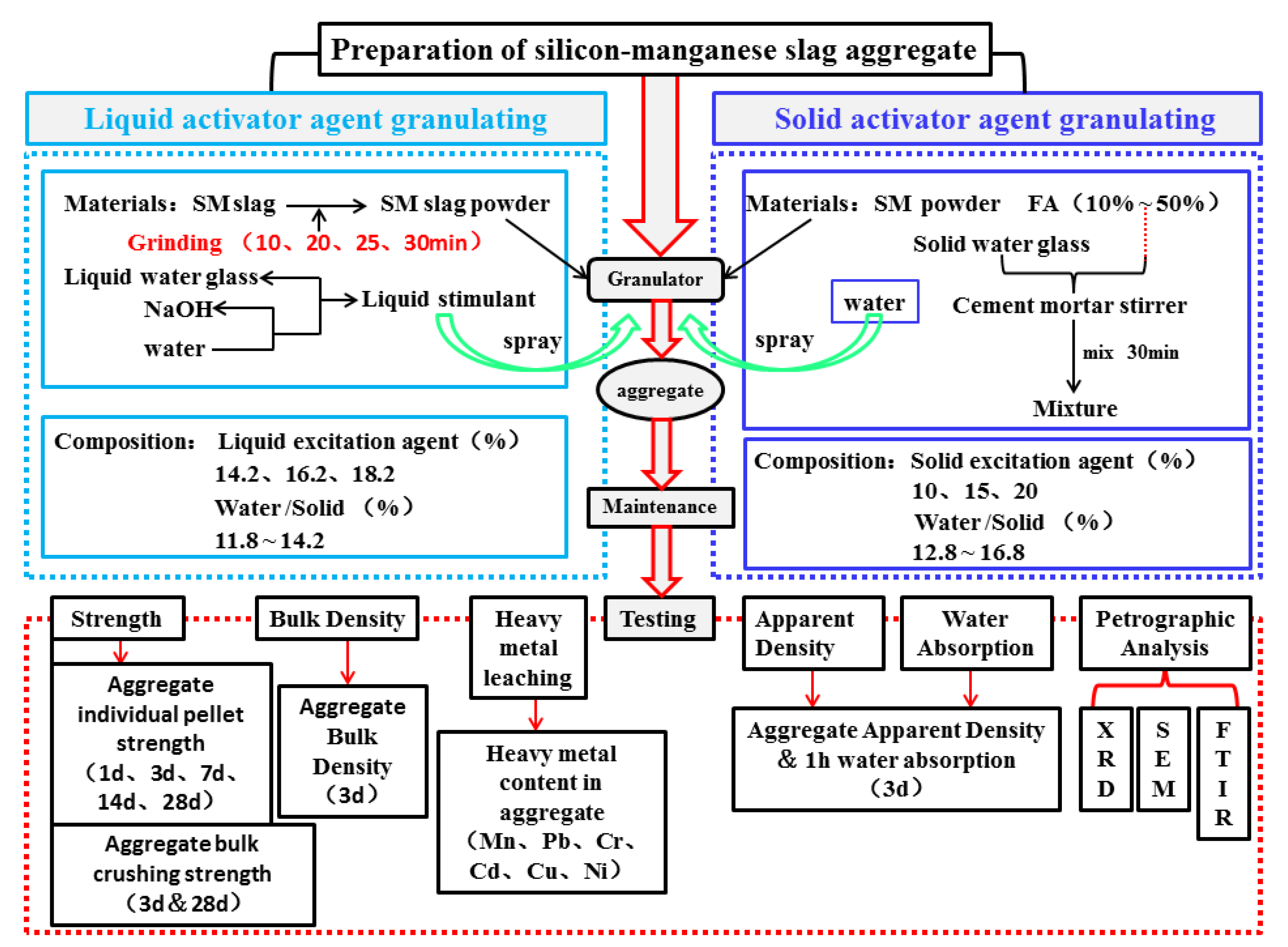
2.2. Experimental Scheme
2.3. Physical and Mechanical Characterisation
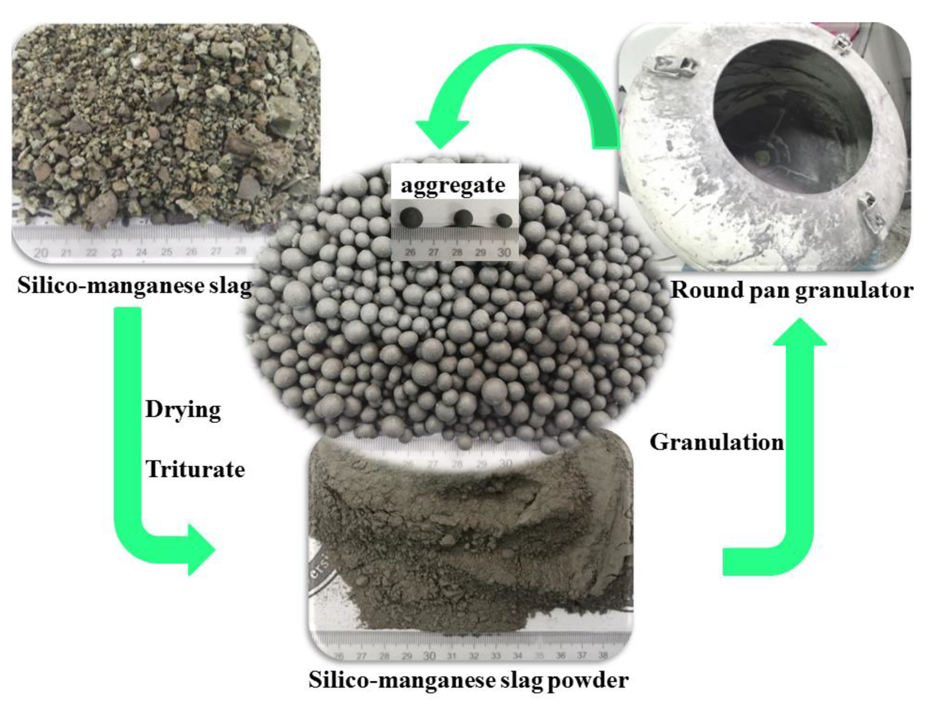
3. Preparation Process of SM Slag Aggregate
3.1. Process Flow of SM Granulation
3.1.1. Liquid Activator Granulation Process
3.1.2. Solid Activator Granulation Process
3.2. Conservation Process of SMNA
3.3. Pelletization Mechanism
4. Performance Test
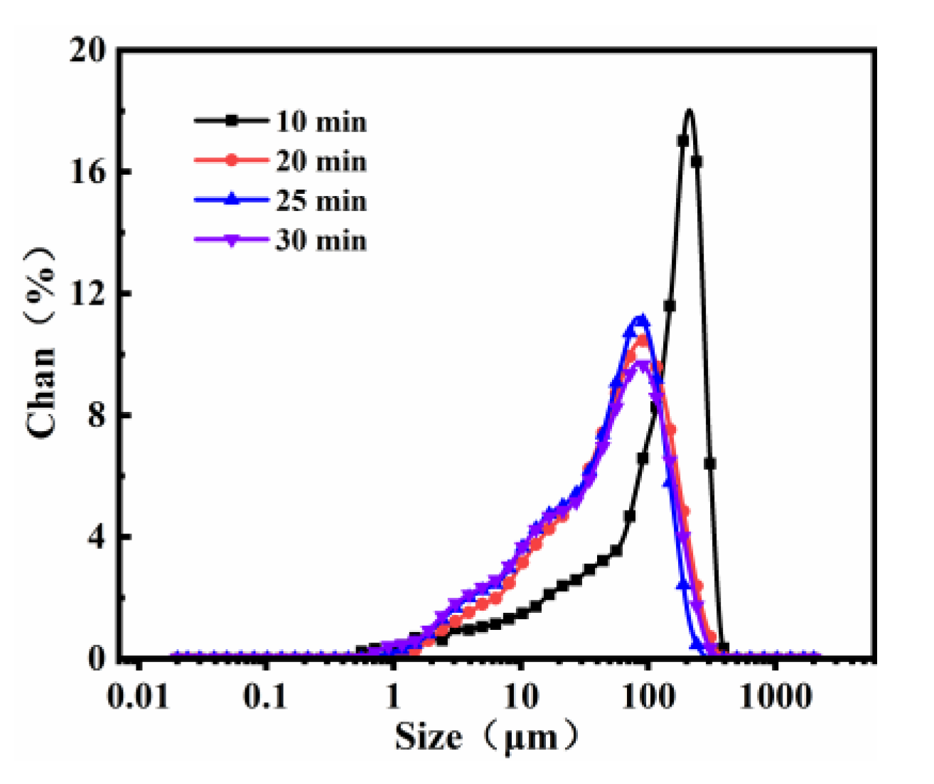
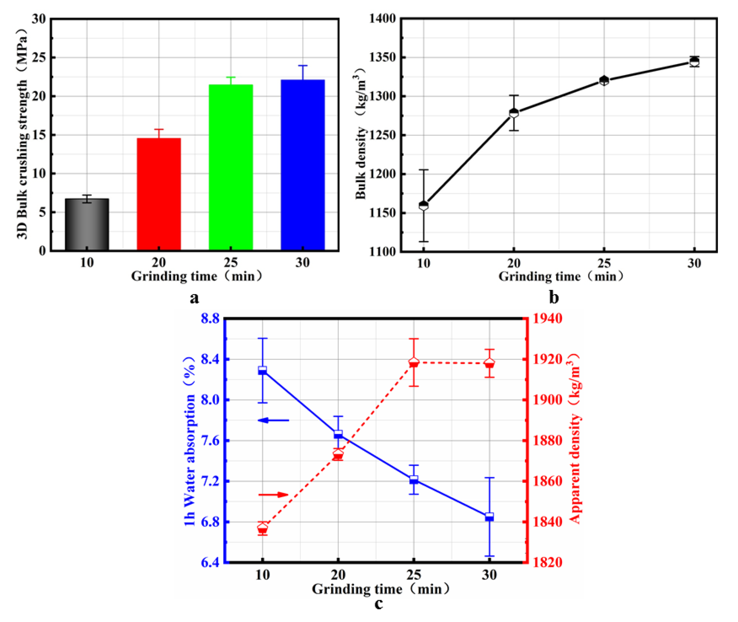
4.1. Effect of the Grinding Time on SMNA
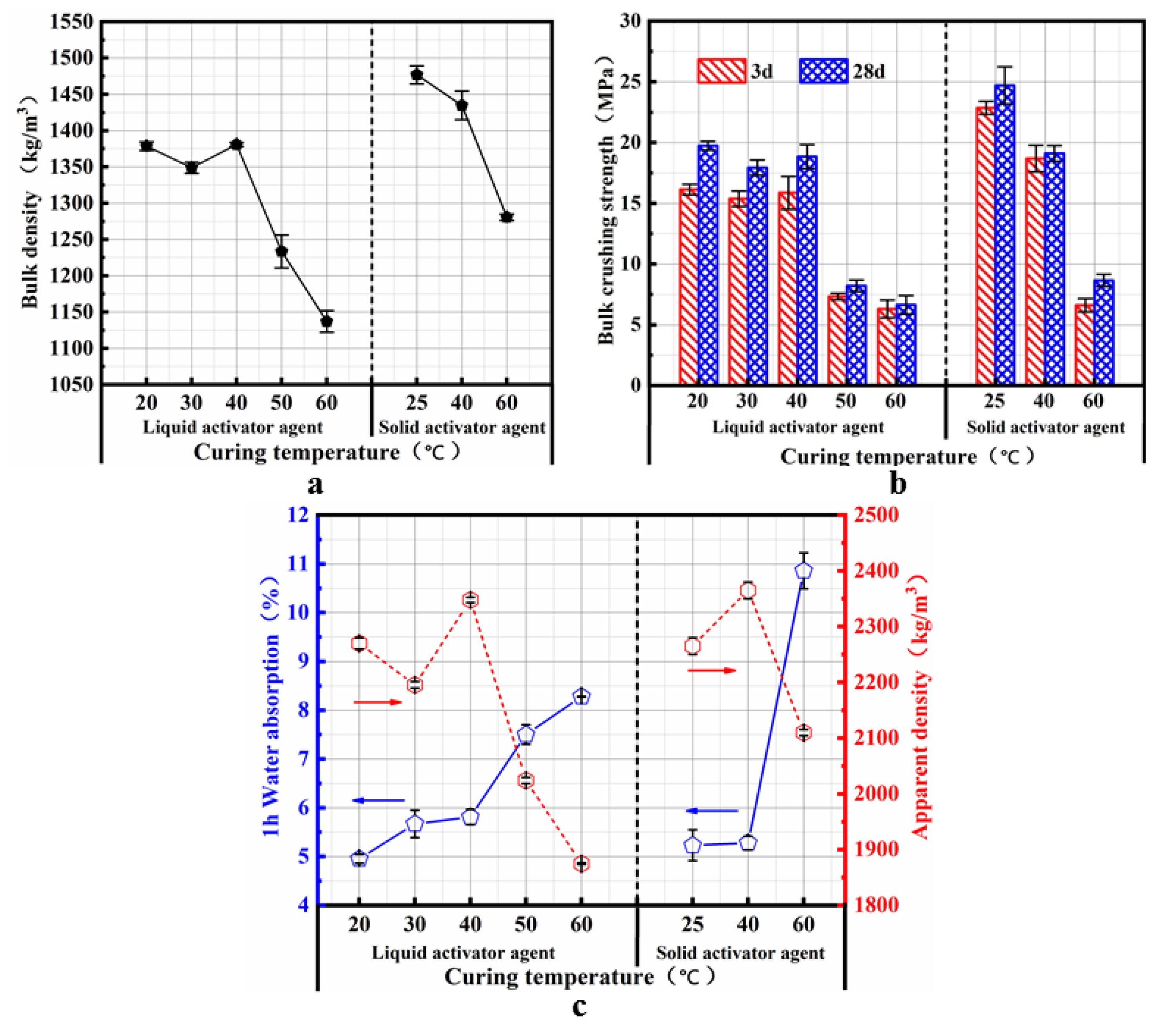
4.2. Influence of the Curing Temperature on the Properties of SMNA
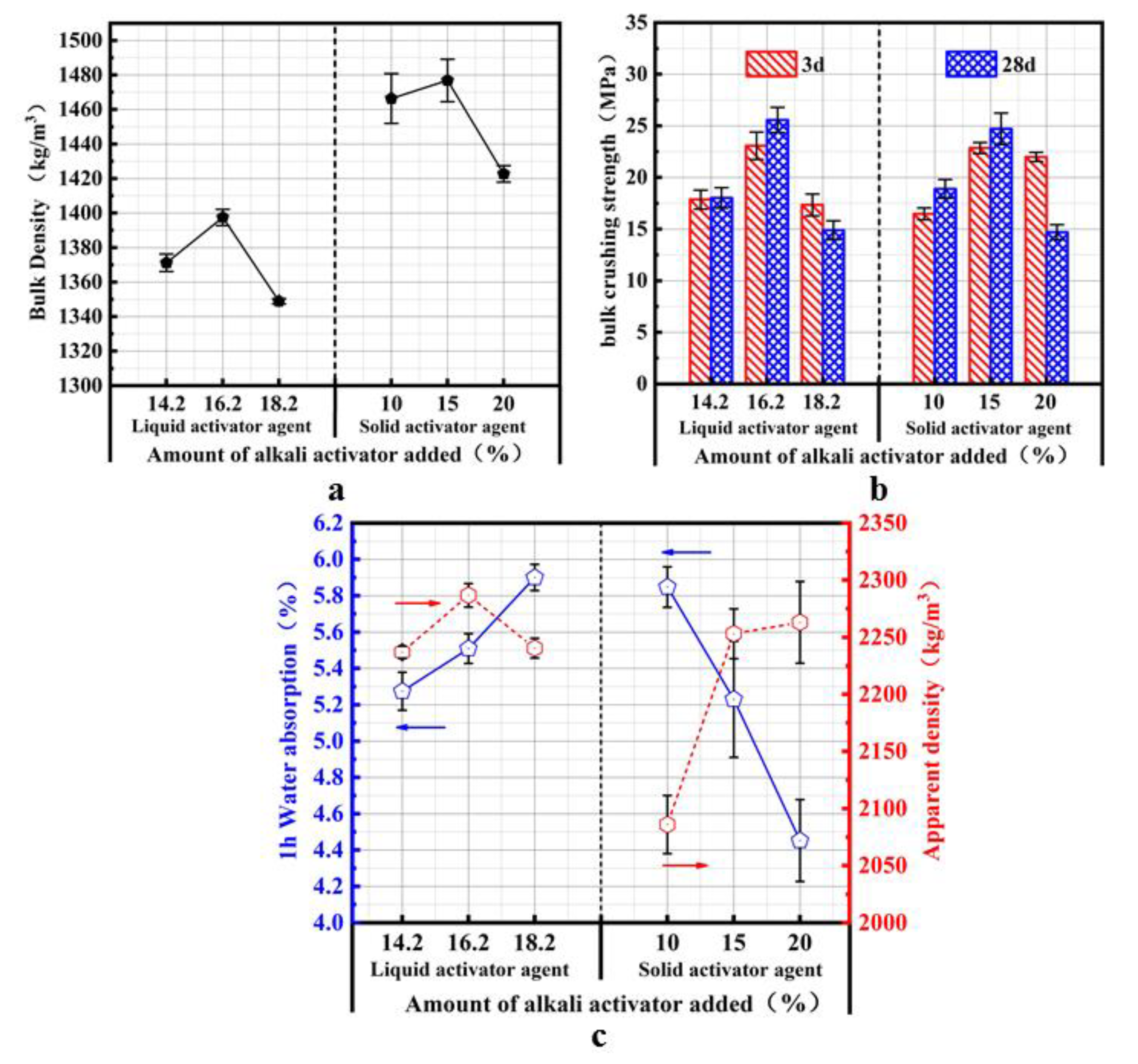
4.3. Influence of the Alkaline Activator on the Properties of SMNA
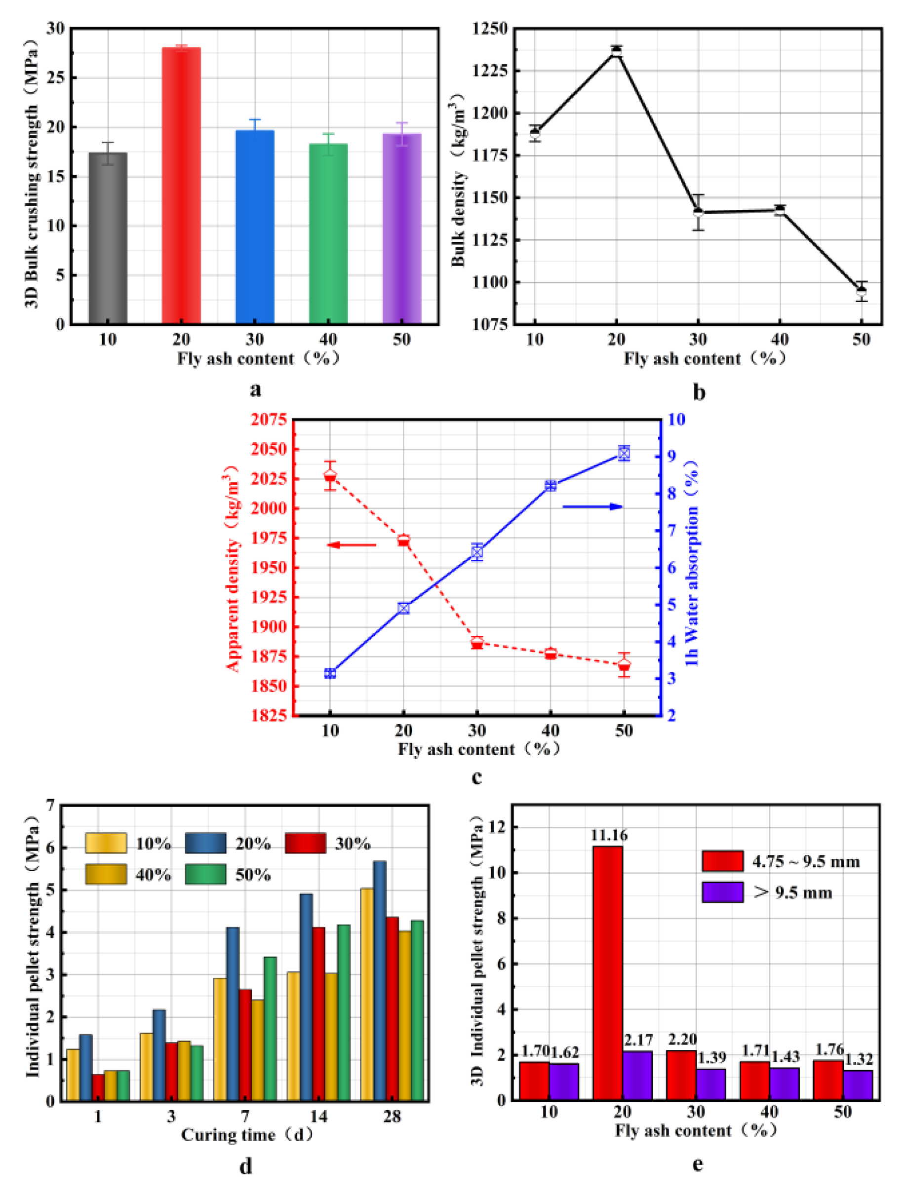
4.4. Influence of the FA Amount on the Properties of SMNA
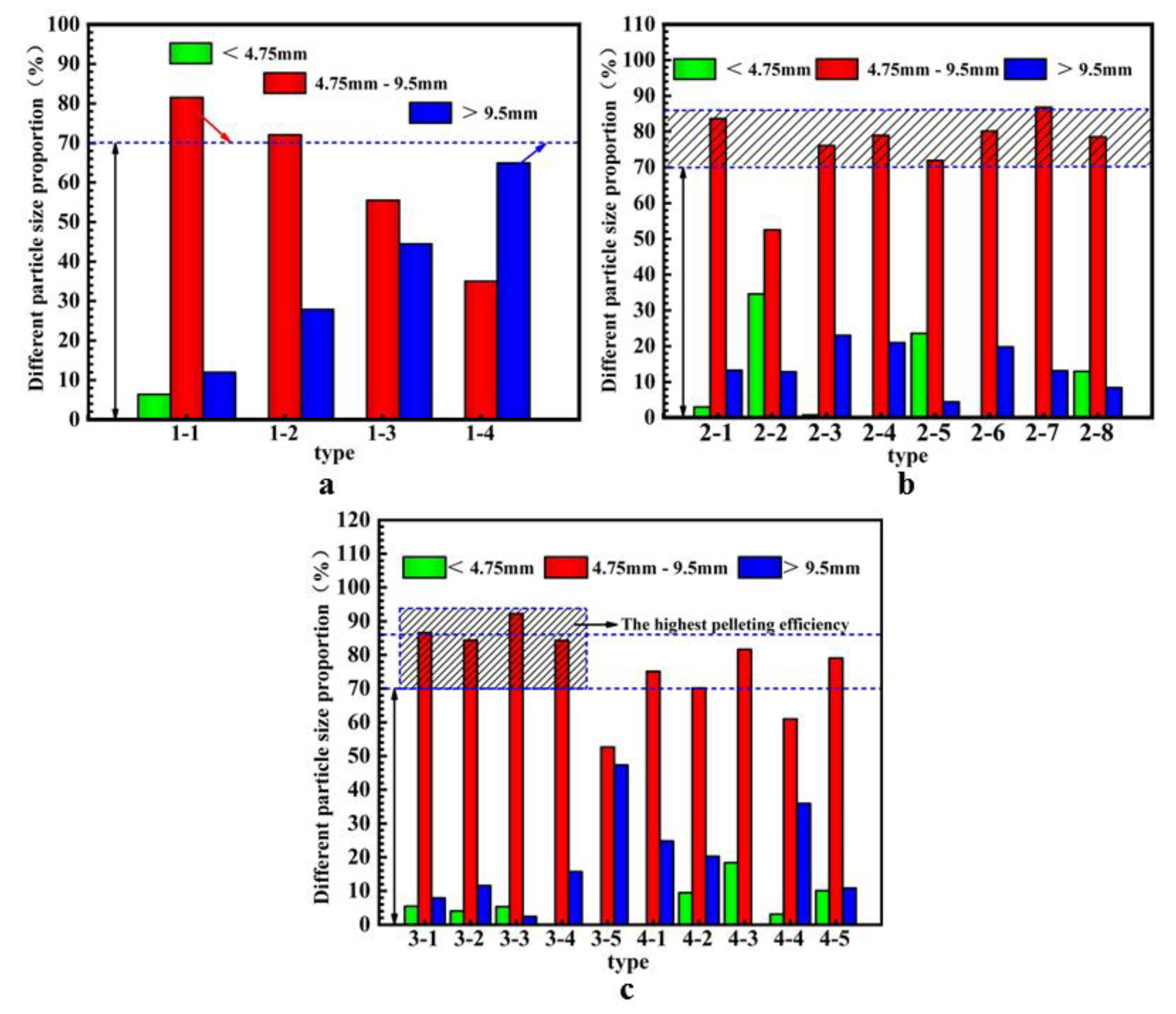
4.5. Granulation Efficiency
5. Microstructural Characterization
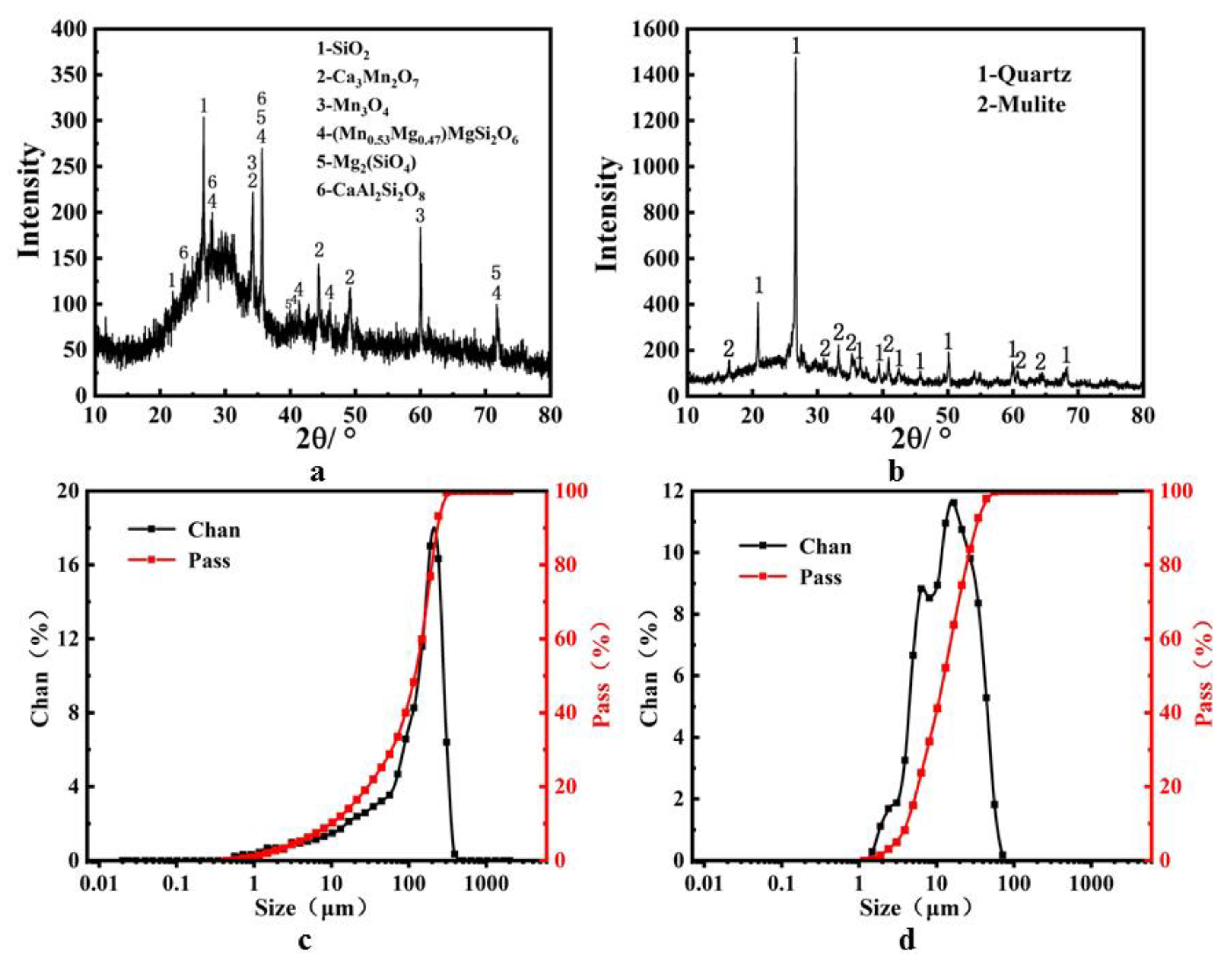
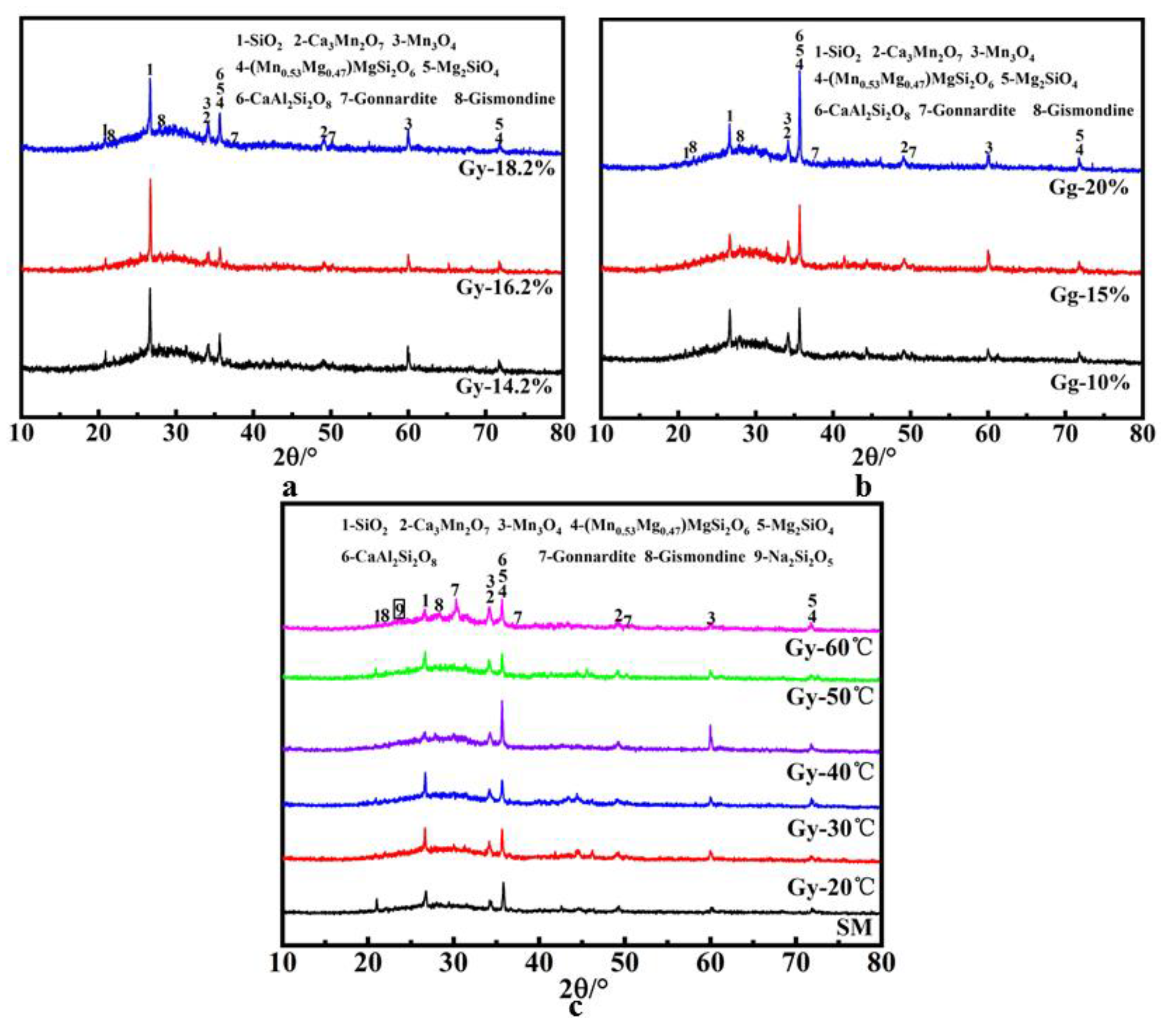
5.1. XRD Analysis
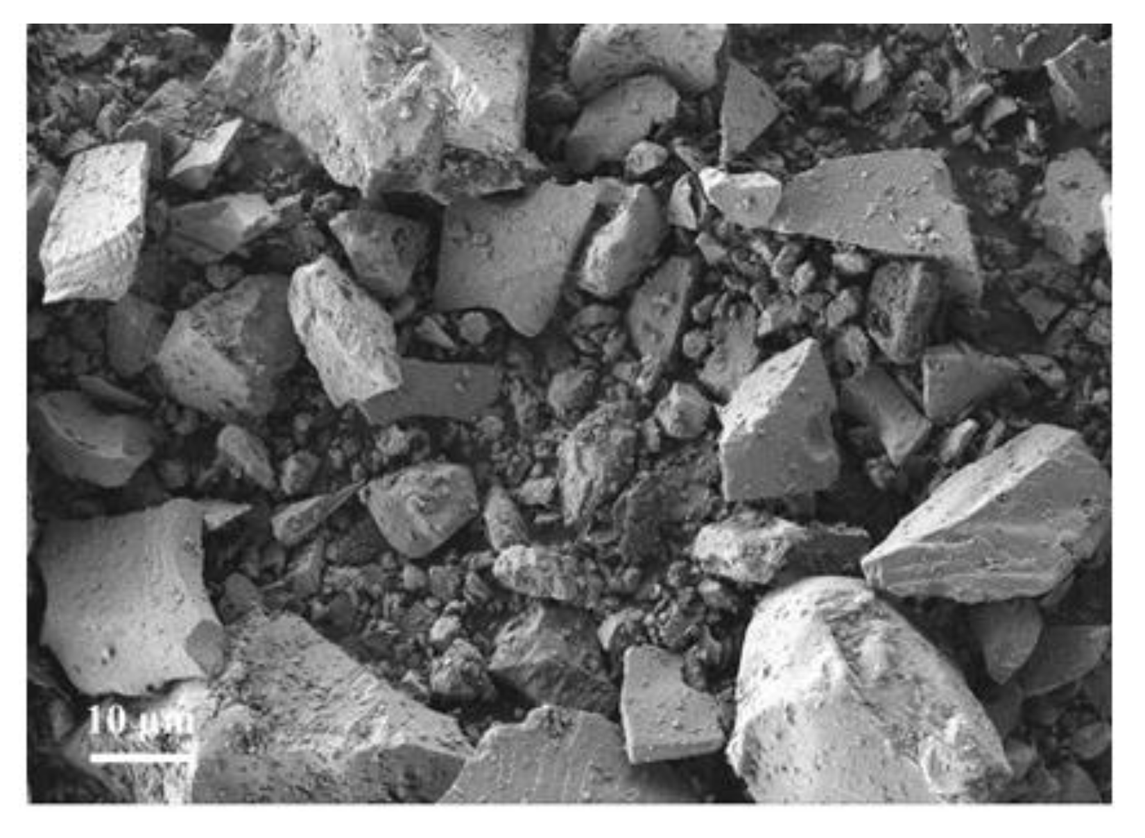
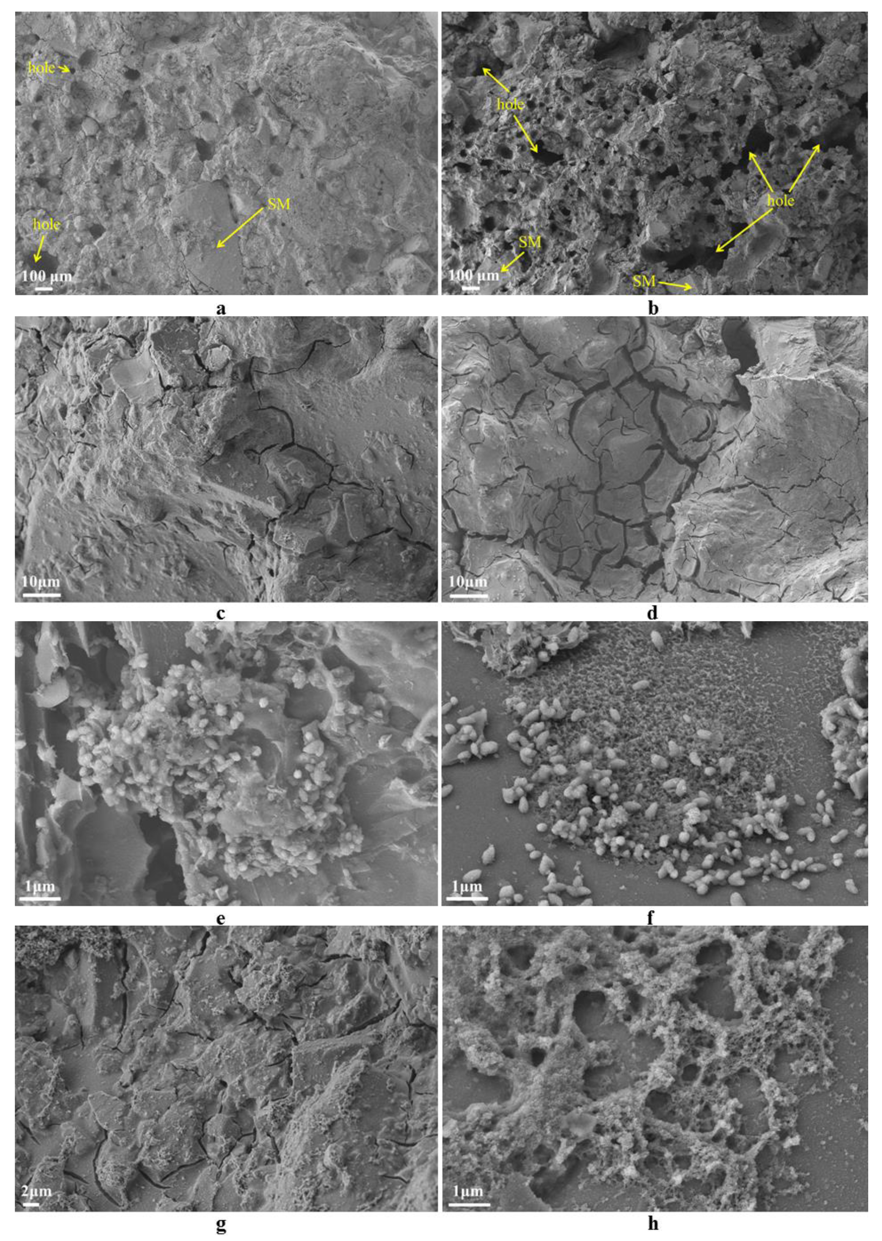
5.2. SEM Analysis
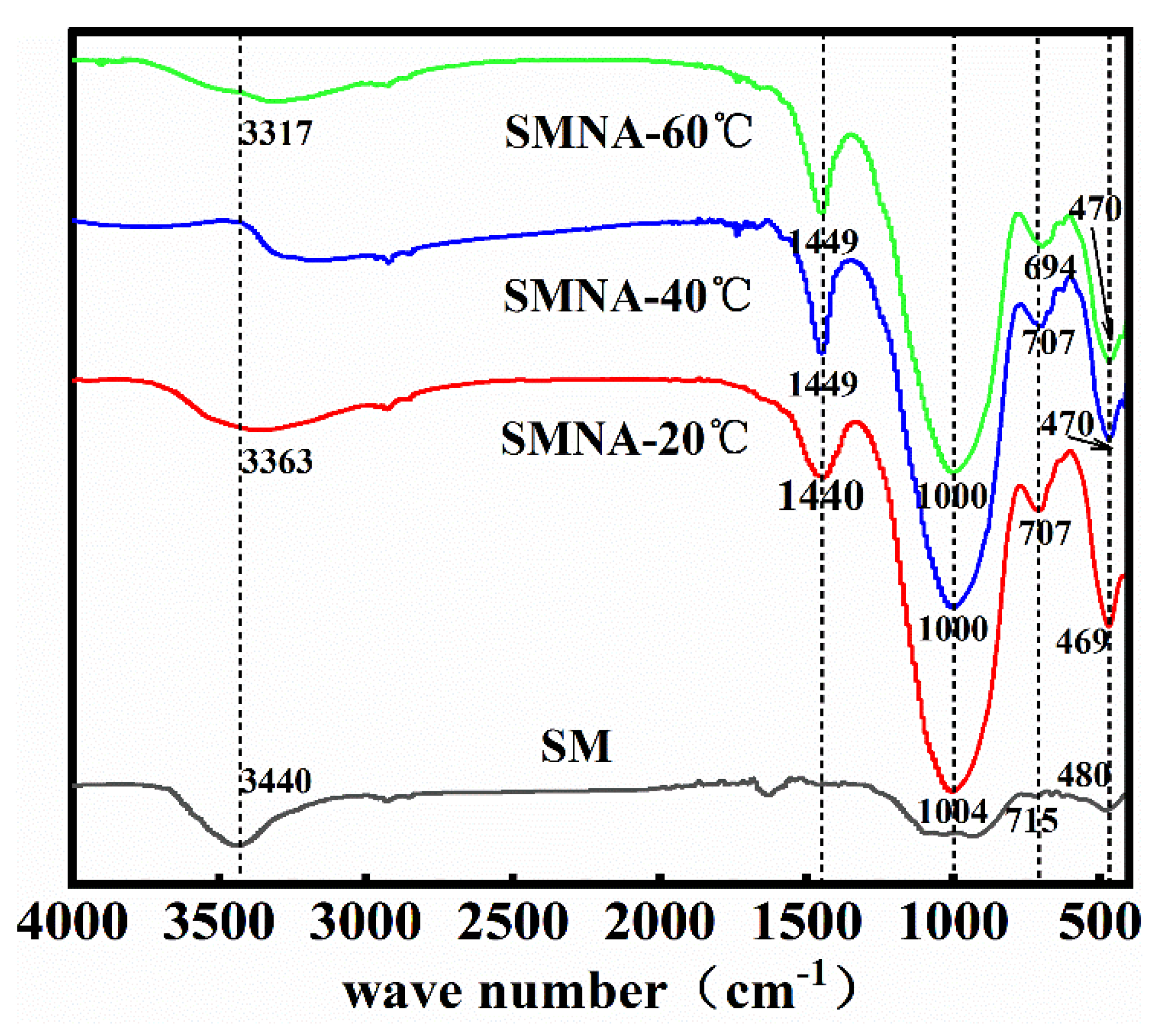
5.3. FTIR Analysis
5.4. Leaching Analysis of Heavy Metals in SMNA
6. Conclusions
- (1)
- Considering the cost and aggregate properties, the room temperature curing was the optimal curing method.
- (2)
- When the amounts of liquid and solid activators are 16.2% and 15%, respectively, the obtained SMNA prepared with silico-manganese (SM) slag showed good properties. It had bulk densities of 1397.5–1476.9 kg/m3, water absorption of 5.38–5.88%, apparent density of 2365.8–2384.7 kg/m3, and pellet strength of 24.7–25.6 MPa.
- (3)
- Considering the single-ball strength and cylinder compressive strength of the aggregate, the aggregate performance reached the optimal value when the FA content was 20%. Its bulk density was 1236.6 kg/m3, water absorption was 4.90%, apparent density was 1973.12 kg/m3, the cylinder compressive strengths after 3 and 28 days were 24.7 MPa and 5.7 MPa, respectively. The addition of FA reduced the bulk density, while the strength was not affected. In the subsequent application, the non-burning lightweight aggregate could be prepared.
- (4)
- By comparing the granulation efficiency of solid and liquid activators, the granulation efficiency of the solid activator was higher, and it was easy to control the aggregate’s particle size.
- (5)
- The results of aggregate toxicity leaching showed that Cu, Cr, Ni, Pb, and Cd in SM slag aggregate could meet the limits of GB 5085.3-2007, without causing any harm to the environment, so they can safely replace the natural aggregate.
Author Contributions
Funding
Institutional Review Board Statement
Informed Consent Statement
Data Availability Statement
Conflicts of Interest
References
- Dong, B.Q.; Luo, X.L.; Tian, K.G.; Hong, S.X.; Wang, Y.S. Preparation and characterization of alkali-activated lithium slag-based artificial aggregates. Mater. Rev. 2021, 35, 15011–15016. [Google Scholar]
- Risdanareni, P.; Schollbach, K.; Wang, J.Y.; Belie, N.D. The effect of NaOH concentration on the mechanical and physical properties of alkali activated fly ash-based artificial lightweight aggregate. Constr. Build. Mater. 2020, 259, 111832. [Google Scholar] [CrossRef]
- Shahane, H.A.; Patel, S. Influence of curing method on characteristics of environment-friendly angular shaped cold bonded fly ash aggregates. J. Build. Eng. 2020, 35, 101997. [Google Scholar] [CrossRef]
- Gu, X.; Li, X.; Zhang, W.; Gao, Y.; Kong, Y.; Liu, J.; Zhang, X. Effects of HPMC on workability and mechanical properties of concrete using iron tailings as aggregates. Materials 2021, 14, 6451. [Google Scholar] [CrossRef] [PubMed]
- Abdullah, A.; Hussin, K.; Abdullah, M.; Yahya, Z.; Sochacki, W.; Razak, R.A.; Bloch, K.; Fansuri, H. The Effects of various concentrations of NaOH on the inter-particle gelation of a fly ash geopolymer aggregate. Materials 2021, 14, 1111. [Google Scholar] [CrossRef] [PubMed]
- Jeon, D.; Yum, W.S.; Song, H.; Yoon, S.; Bae, Y.; Oh, J.E. Use of coal bottom ash and CaO-CaCl2-activated GGBFS binder in the manufacturing of artificial fine aggregates through cold-bonded pelletization. Materials 2020, 13, 5598. [Google Scholar] [CrossRef] [PubMed]
- Mo, L.; Yang, S.; Huang, B.; Xu, L.; Feng, S.; Deng, M. Preparation, microstructure and property of carbonated artificial steel slag aggregate used in concrete. Cem. Concr. Compos. 2020, 113, 103715. [Google Scholar] [CrossRef]
- Li, S.C.; Zhu, C.J.; Ning, W. In Study on the process of producing high quality rock wool by using thermal silicon manganese slag based on pool kiln process. In Proceedings of the National Glass Furnace Technology Symposium, National Glass Furnace Technology Seminar and Exchange Conference, Rizhao, China, 6–9 September 2019. [Google Scholar]
- Dou, L.R. Ultilization of silicomanganese slag in building materials. China Manganese Ind. 2017, 35, 136–138. [Google Scholar]
- Huang, T.Z. Study on the Utilization of SiMn Slag in Construction Materials. Master’s Thesis, Chongqing University, Chongqing, China, 2012. [Google Scholar]
- Patil, A.V.; Pande, A.M. Behaviour of silico manganese slag manufactured aggregate as material for road and rail track construction. Adv. Mater. Res. 2011, 255–260, 3258–3262. [Google Scholar] [CrossRef]
- Li, W.B.; Yu, W.G.; Tian, B.S. Production of ordinary portland cement from silico-manganese slag. China Cem. 2003, 56–57. [Google Scholar] [CrossRef]
- Allahverdi, A.; Ahmadnezhad, S. Mechanical activation of silicomanganese slag and its influence on the properties of portland slag cement. Powder Technol. 2014, 251, 41–51. [Google Scholar] [CrossRef]
- Zhang, D.Y.; Ju, B.X.; Li, P.; Zhan, L.; Zhang, C.; Zhang, J.L.; Dai, L.W.; He, Z.Y. Experimental study of compound admixture mixed with siliconmanganese slag. Coal Ash 2012, 24, 18–22. [Google Scholar]
- Frías, M.; Rojas, M.I.S.D.; Rodríguez, C. The influence of SiMn slag on chemical resistance of blended cement pastes. Constr. Build. Mater. 2009, 23, 1472–1475. [Google Scholar] [CrossRef]
- Ting, M.Z.Y.; Wong, K.S.; Rahman, M.E.; Joo, M.S. Mechanical and durability performance of marine sand and seawater concrete incorporating silicomanganese slag as coarse aggregate. Constr. Build. Mater. 2020, 254, 119195. [Google Scholar] [CrossRef]
- Colangelo, F.; Messina, F.; Cioffi, R. Recycling of MSWI fly ash by means of cementitious double step cold bonding pelletization: Technological assessment for the production of lightweight artificial aggregates. J. Hazard. Mater. 2015, 299, 181–191. [Google Scholar] [CrossRef] [PubMed]
- Tajra, F.; Elrahman, M.A.; Lehmann, C.; Stephan, D. Properties of lightweight concrete made with core-shell structured lightweight aggregate. Constr. Build. Mater. 2019, 205, 39–51. [Google Scholar] [CrossRef]
- Tang, P.; Xuan, D.; Cheng, H.W.; Poon, C.S.; Tsang, D.C.W. Use of CO2 curing to enhance the properties of cold bonded lightweight aggregates (CBLAs) produced with concrete slurry waste (CSW) and fine incineration bottom ash (IBA). J. Hazard. Mater. 2020, 381, 120951. [Google Scholar] [CrossRef]
- Tang, P.; Brouwers, H.J.H. Integral recycling of municipal solid waste incineration (MSWI) bottom ash fines (0–2 mm) and industrial powder wastes by cold-bonding pelletization. Waste Manage. 2017, 62, 125–138. [Google Scholar] [CrossRef] [PubMed]
- Tian, K.G.; Wang, Y.S.; Hong, S.X.; Zhang, J.R.; Hou, D.S.; Dong, B.Q.; Xing, F. Alkali-activated artificial aggregates fabricated by red mud and fly ash: Performance and microstructure. Constr. Build. Mater. 2021, 281, 122522. [Google Scholar] [CrossRef]
- Tang, P.; Xuan, D.; Li, J.; Cheng, H.W.; Poon, C.S.; Tsang, D.C.W. Investigation of cold bonded lightweight aggregates produced with incineration sewage sludge ash (ISSA) and cementitious waste. J. Clean. Prod. 2020, 251, 119709. [Google Scholar] [CrossRef]
- Gómez, M.; Peisino, L.E.; Kreiker, J.; Gaggino, R.; Cappelletti, A.L.; Martín, S.E.; Uberman, P.M.; Positieri, M.; Raggiotti, B.B. Stabilization of hazardous compounds from WEEE plastic: Development of a novel core-shell recycled plastic aggregate for use in building materials. Constr. Build. Mater. 2020, 230, 116977. [Google Scholar] [CrossRef]
- Geetha, S.; Ramamurthy, K. Environmental friendly technology of cold-bonded bottom ash aggregate manufacture through chemical activation. J. Clean. Prod. 2010, 18, 1563–1569. [Google Scholar] [CrossRef]
- Narattha, C.; Chaipanich, A. Phase characterizations, physical properties and strength of environment-friendly cold-bonded fly ash lightweight aggregates. J. Clean. Prod. 2018, 171, 1094–1100. [Google Scholar] [CrossRef]
- Shang, X.; Li, J.; Zhan, B. Properties of sustainable cellular concrete prepared with environment-friendly capsule aggregates. J. Clean. Prod. 2020, 267, 122018. [Google Scholar] [CrossRef]
- Tuncel, E.Y.; Pekmezci, B.Y. A sustainable cold bonded lightweight PCM aggregate production: Its effects on concrete properties. Constr. Build. Mater. 2018, 181, 199–216. [Google Scholar] [CrossRef]
- Alqahtani, F.K.; Rashid, K.; Zafar, I.; Iqbal Khan, M. Assessment of morphological characteristics and physico-mechanical properties of geopolymer green foam lightweight aggregate formulated by microwave irradiation. J. Build. Eng. 2021, 35, 102081. [Google Scholar] [CrossRef]
- Manikandan, R.; Ramamurthy, K. Effect of curing method on characteristics of cold bonded fly ash aggregates. Cem. Concr. Compos. 2008, 30, 848–853. [Google Scholar] [CrossRef]
- Vasugi, V.; Ramamurthy, K. Identification of design parameters influencing manufacture and properties of cold-bonded pond ash aggregate. Mater. Des. 2014, 54, 264–278. [Google Scholar] [CrossRef]
- Zhu, W.X.; Feng, L.; Zhou, H.M.; Qin, Y.C.; Luan, H.X. Analysis on the development and application of a new type of ash haydite. Concrete 2017, 59–62. [Google Scholar] [CrossRef]
- Wang, K.T. Reaction Mechanism and Applications of ALKALI-BASED Geopolymers At Low Temperature and Vacuum Conditions. Ph.D. Thesis, Guangxi University, Nanning, China, 2016. [Google Scholar]
- Cheng, T.W.; Chiu, J.P. Fire-resistant geopolymer produced by granulated blast furnace slag. Miner. Eng. 2003, 16, 203–210. [Google Scholar] [CrossRef]
- Nazari, A.; Bagheri, A.; Riahi, S. Properties of geopolymer with seeded fly ash and rice husk bark ash. Mater. Sci. Eng. A 2011, 528, 7395–7401. [Google Scholar] [CrossRef]
- Zhang, H.B.; Zheng, Z.G.; Kou, J.L. Mechanical properties of silica fume-aluminum oxide geopolymer. J. Build. Mater. 2017, 20, 288–292. [Google Scholar]
- Baykal, G.; Dven, A.G. Utilization of fly ash by pelletization process; theory, application areas and research results. Resour. Conserv. Recycl. 2000, 30, 59–77. [Google Scholar] [CrossRef]
- Elisabeth, V.; Tran, L.H.; Pasquier, L.C.; Blais, J.F.; Mercier, G. Valorization of apatite mining flotation residues by the manufacture of artificial aggregates. Resour., Conserv. Recycl. 2021, 171, 106605. [Google Scholar]
- Manikandan, R.; Ramamurthy, K. Influence of fineness of fly ash on the aggregate pelletization process. Cem. Concr. Compos. 2007, 29, 456–464. [Google Scholar] [CrossRef]
- Chen, Z.; Li, J.S.; Zhan, B.J.; Sharma, U.; Poon, C.S. Compressive strength and microstructural properties of dry-mixed geopolymer pastes synthesized from GGBS and sewage sludge ash. Constr. Build. Mater. 2018, 182, 597–607. [Google Scholar] [CrossRef]
- Yaseri, S.; Hajiaghaei, G.; Mohammadi, F.; Mahdikhani, M.; Farokhzad, R. The role of synthesis parameters on the workability, setting and strength properties of binary binder based geopolymer paste. Constr. Build. Mater. 2017, 157, 534–545. [Google Scholar] [CrossRef]
- Lodeiro, I.G.; Macphee, D.E.; Palomo, A.; Fernández-Jiménez, A. Effect of alkalis on fresh C–S–H gels. FTIR analysis. Cem. Concr. Compos. 2009, 39, 147–153. [Google Scholar] [CrossRef]
- Sha, D.; Pan, B.F.; Li, Y.C.; Wang, B.M. Studies on preparation and performance of alkali-activated coal-based synthetic natural gas slag geopolymer. China J. Highw. Transp. 2021, 34, 234–244. [Google Scholar]
- Liu, X.; Jiang, J.; Zhang, H.; Li, M.; Zhang, Z. Thermal stability and microstructure of metakaolin-based geopolymer blended with rice husk ash. Appl. Clay Sci. 2020, 196, 105769. [Google Scholar] [CrossRef]
- Aiken, T.A.; Kwasny, J.; Wei, S.; Soutsos, M.N. Effect of slag content and activator dosage on the resistance of fly ash geopolymer binders to sulfuric acid attack. Cem. Concr. Res. 2018, 111, 23–40. [Google Scholar] [CrossRef] [Green Version]
- Chen, K.; Lin, W.T.; Liu, W. Effect of NaOH concentration on properties and microstructure of a novel reactive ultra-fine fly ash geopolymer. Adv. Powder Technol. 2021, 32, 2929–2939. [Google Scholar] [CrossRef]
- Yu, Q.Q.; Li, S.L.; Li, H.; Chai, X.N.; Bi, X.Y.; Liu, J.L.; Ohnuki, T. Synthesis and characterization of Mn-slag based geopolymer for immobilization of Co. J. Clean. Prod. 2019, 234, 97–104. [Google Scholar] [CrossRef]
- Sha, D.; Pan, B.F.; Sun, Y.R. Investigation on mechanical properties and microstructure of coal-based synthetic natural gas slag (CSNGS) geopolymer. Constr. Build. Mater. 2020, 259, 119793. [Google Scholar] [CrossRef]


| Material | SiO2 | Al2O3 | CaO | MgO | MnO | Fe2O3 | K2O | SO3 | Na2O | Others |
|---|---|---|---|---|---|---|---|---|---|---|
| SM | 42.17 | 21.66 | 20.71 | 5.60 | 5.77 | - | 1.08 | 1.37 | - | 1.973 |
| FA | 44.8 | 22.6 | 6.2 | 1.8 | - | 5.7 | 1.7 | - | 1.5 | 15.7 |
| Type | SM (%) | Ratio of the Liquid Activator and Raw Material in the Mixture (%) | Curing Temperature (°C) | Curing Time (Day) |
|---|---|---|---|---|
| 1-1 | 100 | 16.2 | 60 | 3 |
| 1-2 | 100 | 16.2 | 60 | 3 |
| 1-3 | 100 | 16.2 | 60 | 3 |
| 1-4 | 100 | 16.2 | 60 | 3 |
| 2-1 | 100 | 14.2 | 25 | 3; 28 |
| 2-2 | 100 | 16.2 | 25 | 3; 28 |
| 2-3 | 100 | 18.2 | 25 | 3; 28 |
| 2-4 | 100 | 16.2 | 20 | 3; 28 |
| 2-5 | 100 | 16.2 | 30 | 3; 28 |
| 2-6 | 100 | 16.2 | 40 | 3; 28 |
| 2-7 | 100 | 16.2 | 50 | 3; 28 |
| 2-8 | 100 | 16.2 | 60 | 3; 28 |
| Type | SM (%) | Ratio of the Solid Activator and Raw Material in the Mixture (%) | Curing Temperature (°C) | Curing Time (Day) |
|---|---|---|---|---|
| 3-1 | 100 | 10 | 25 | 3; 28 |
| 3-2 | 100 | 15 | 25 | 3; 28 |
| 3-3 | 100 | 20 | 25 | 3; 28 |
| 3-4 | 100 | 15 | 40 | 3; 28 |
| 3-5 | 100 | 15 | 60 | 3; 28 |
| Type | SM (%) | FA (%) | Ratio of the Solid Activator and Raw Material in the Mixture (%) | Curing Temperature (°C) | Curing Time (Day) |
|---|---|---|---|---|---|
| 4-1 | 90 | 10 | 15 | 25 | 3; 28 |
| 4-2 | 80 | 20 | 15 | 25 | 3; 28 |
| 4-3 | 70 | 30 | 15 | 25 | 3; 28 |
| 4-4 | 60 | 40 | 15 | 25 | 3; 28 |
| 4-5 | 50 | 50 | 15 | 25 | 3; 28 |
| Mn | Pb | Cr | Cd | Co | Ni | Cu |
|---|---|---|---|---|---|---|
| 5.18 × 10⁴ | ≤0.005 | 28.62 | ≤0.005 | ≤0.005 | 25.30 | 18.75 |
| Type | Mn | Cr | Cu | Ni | Pb |
|---|---|---|---|---|---|
| 2-1 | 0.2540 | ≤0.005 | ≤0.005 | ≤0.010 | ≤0.005 |
| 2-2 | 0.1950 | ≤0.005 | ≤0.005 | ≤0.010 | ≤0.005 |
| 2-3 | 0.1975 | ≤0.005 | ≤0.005 | ≤0.010 | ≤0.005 |
| 3-1 | 0.1585 | ≤0.005 | ≤0.005 | ≤0.010 | ≤0.005 |
| 3-2 | 0.0970 | ≤0.005 | ≤0.005 | ≤0.010 | ≤0.005 |
| 3-3 | 11.27 | ≤0.005 | ≤0.005 | ≤0.010 | ≤0.005 |
| 2-6 | 0.1855 | ≤0.005 | ≤0.005 | ≤0.010 | ≤0.005 |
| 2-7 | 0.3210 | ≤0.005 | ≤0.005 | ≤0.010 | ≤0.005 |
| 2-8 | 0.2815 | ≤0.005 | ≤0.005 | ≤0.010 | ≤0.005 |
| GB5085.3-2007 (limit value) | - | 15 | 100 | 5 | 5 |
Publisher’s Note: MDPI stays neutral with regard to jurisdictional claims in published maps and institutional affiliations. |
© 2021 by the authors. Licensee MDPI, Basel, Switzerland. This article is an open access article distributed under the terms and conditions of the Creative Commons Attribution (CC BY) license (https://creativecommons.org/licenses/by/4.0/).
Share and Cite
Xing, Z.; Han, F.; Tian, J.; Xu, Z.; Wang, J.; Liu, T.; Zheng, B.; Huang, J. Preparation and Characterization of the Functional Properties of Synthetic Aggregates from Silico-Manganese Slag. Materials 2021, 14, 7303. https://doi.org/10.3390/ma14237303
Xing Z, Han F, Tian J, Xu Z, Wang J, Liu T, Zheng B, Huang J. Preparation and Characterization of the Functional Properties of Synthetic Aggregates from Silico-Manganese Slag. Materials. 2021; 14(23):7303. https://doi.org/10.3390/ma14237303
Chicago/Turabian StyleXing, Zhibing, Fenglan Han, Jiuliang Tian, Zhichao Xu, Jiaqi Wang, Tengteng Liu, Bin Zheng, and Jiahe Huang. 2021. "Preparation and Characterization of the Functional Properties of Synthetic Aggregates from Silico-Manganese Slag" Materials 14, no. 23: 7303. https://doi.org/10.3390/ma14237303