
Influence of Spatial Dispersion on Propagation Properties of Waveguides Based on Hyperbolic Metamaterial

Abstract
:1. Introduction
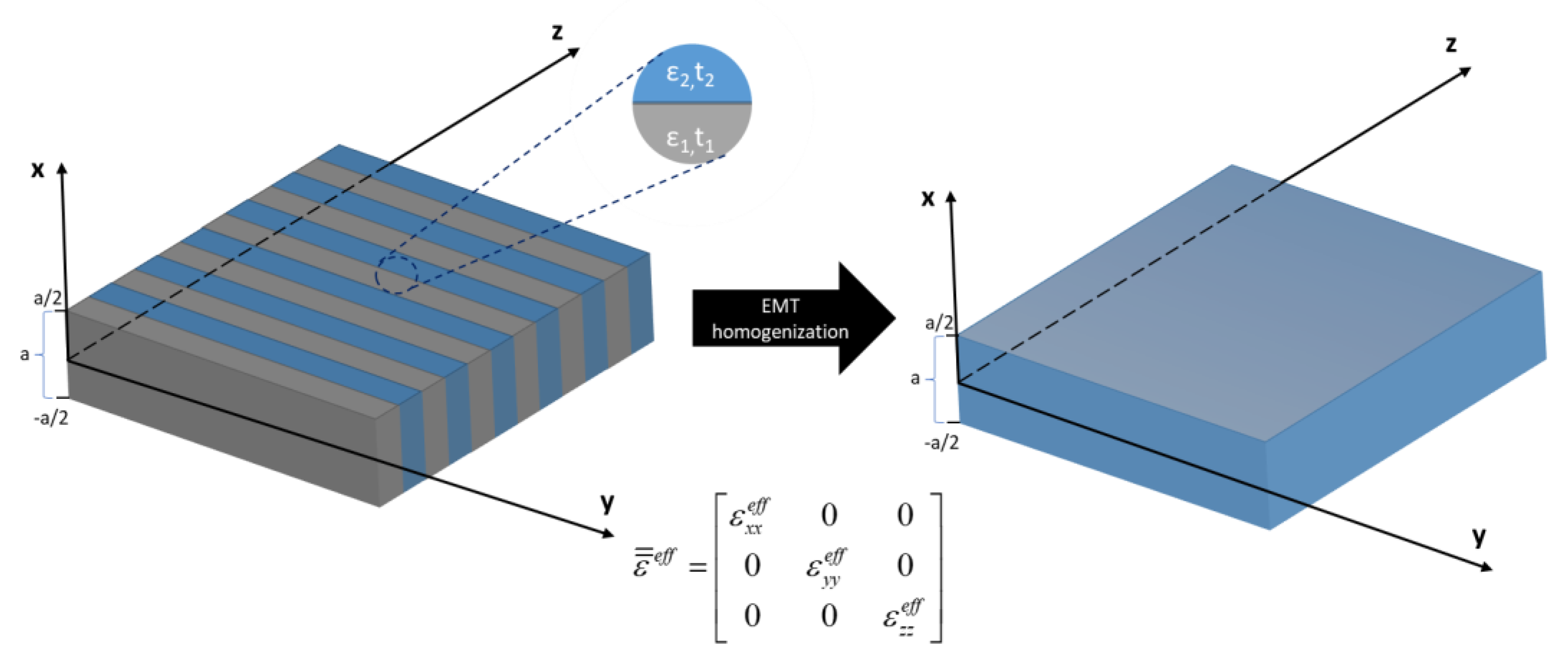
2. Theory
3. Results and Discussion
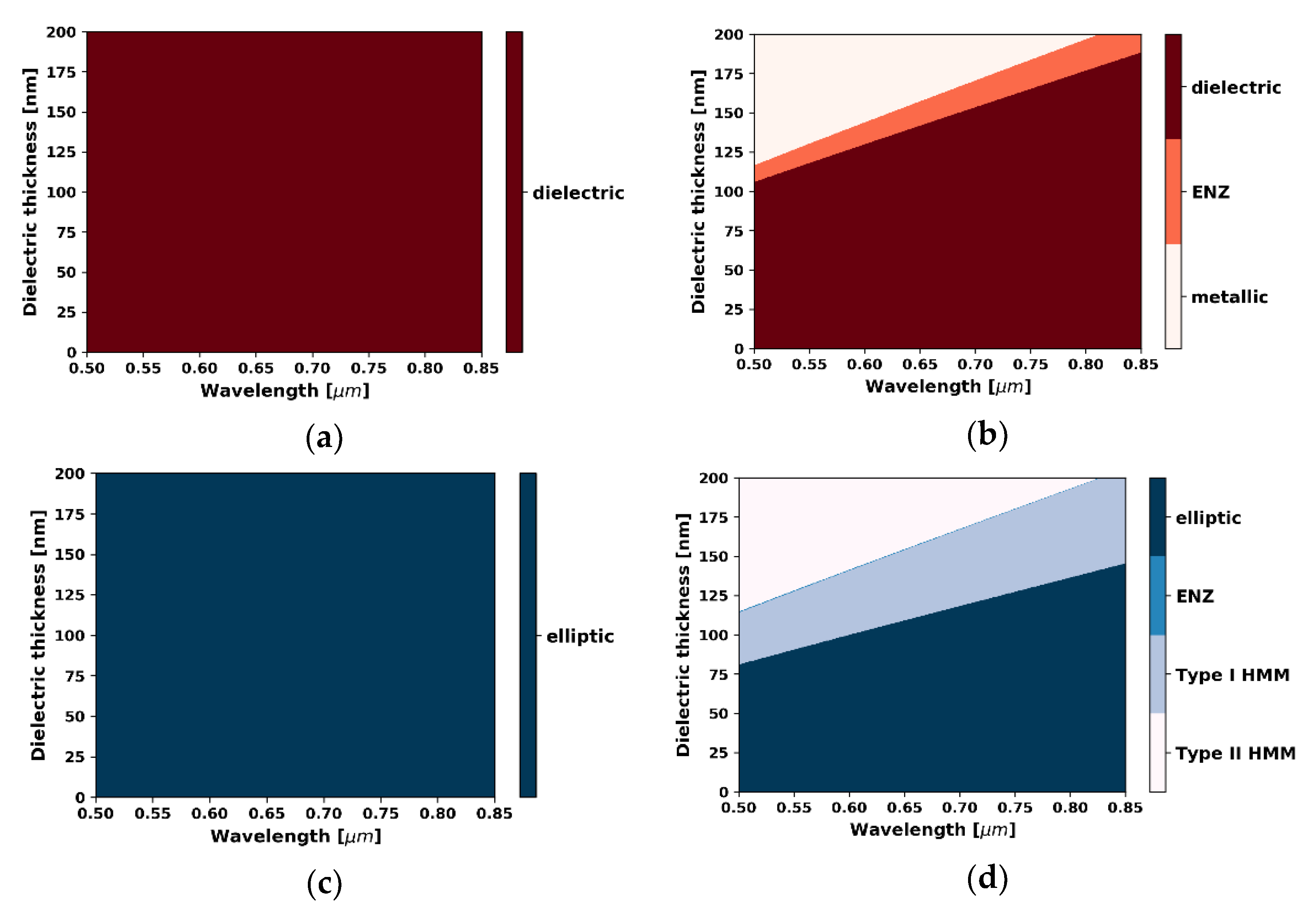
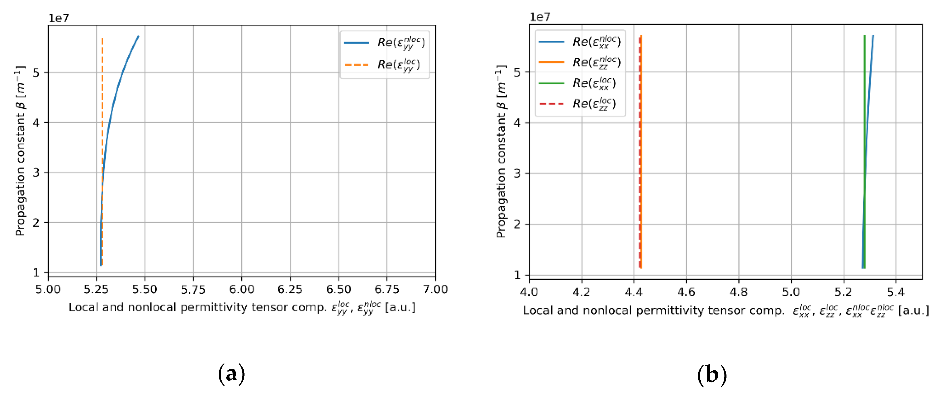
3.1. The Local and Nonlocal Response of the Guiding HMM Medium
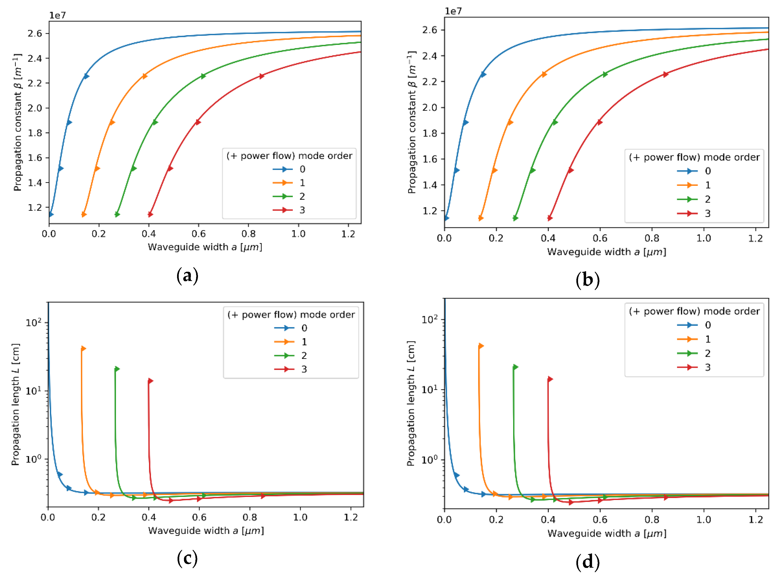
3.2. Analysis of Propagation Properties
3.2.1. Case 1—The Core Layer with 5 nm Dielectric Layer
3.2.2. Case 2—The Core Layer with 80 nm Dielectric Layer
3.2.3. Case 3—The Core Layer with 110 Nm Dielectric Layer
3.2.4. Case 4—The Core Layer with 175 Nm Dielectric Layer
4. Conclusions
Author Contributions
Funding
Institutional Review Board Statement
Informed Consent Statement
Data Availability Statement
Conflicts of Interest
References
- Shalaev, V.M. Optical negative-index metamaterials. Nat. Photon 2007, 1, 41–48. [Google Scholar] [CrossRef]
- Soukoulis, C.M.; Linden, S.; Wegener, M. PHYSICS: Negative refractive index at optical wavelengths. Science 2007, 315, 47–49. [Google Scholar] [CrossRef]
- Fang, N. Sub-diffraction-limited optical imaging with a silver superlens. Science 2005, 308, 534–537. [Google Scholar] [CrossRef] [PubMed] [Green Version]
- Zhu, S.; Zhang, X. Metamaterials: Artificial materials beyond nature. Natl. Sci. Rev. 2018, 5, 131. [Google Scholar] [CrossRef] [Green Version]
- Liu, Z.; Lee, H.; Xiong, Y.; Sun, C.; Zhang, X. Far-field optical hyperlens magnifying sub-diffraction-limited objects. Science 2007, 315, 1686. [Google Scholar] [CrossRef] [Green Version]
- Shekhar, P.; Atkinson, J.; Jacob, Z. Hyperbolic metamaterials: Fundamentals and applications. Nano Converg. 2014, 1, 14. [Google Scholar] [CrossRef] [Green Version]
- Kim, K.-H.; No, Y.-S.; Chang, S.; Choi, J.-H.; Park, H.-G. Invisible hyperbolic metamaterial nanotube at visible frequency. Sci. Rep. 2015, 5, 16027. [Google Scholar] [CrossRef] [Green Version]
- Galfsky, T.; Krishnamoorthy, H.N.S.; Newman, W.; Narimanov, E.E.; Jacob, Z.; Menon, V.M. Active hyperbolic metamaterials: Enhanced spontaneous emission and light extraction. Optica 2015, 2, 62. [Google Scholar] [CrossRef]
- Drachev, V.P.; Podolskiy, V.A.; Kildishev, A.V. Hyperbolic metamaterials: New physics behind a classical problem. Opt. Express 2013, 21, 15048. [Google Scholar] [CrossRef] [PubMed]
- Poddubny, A.N.; Belov, P.A.; Kivshar, Y.S. Spontaneous radiation of a finite-size dipole emitter in hyperbolic media. Phys. Rev. A 2011, 84, 023807. [Google Scholar] [CrossRef] [Green Version]
- Sreekanth, K.V.; Alapan, Y.; ElKabbash, M.; Ilker, E.; Hinczewski, M.; Gurkan, U.A.; De Luca, A.; Strangi, G. Extreme sensitivity biosensing platform based on hyperbolic metamaterials. Nat. Mater. 2016, 15, 621–627. [Google Scholar] [CrossRef] [PubMed] [Green Version]
- Baqir, M.A.; Farmani, A.; Fatima, T.; Raza, M.R.; Shaukat, S.F.; Mir, A. Nanoscale, tunable, and highly sensitive biosensor utilizing hyperbolic metamaterials in the near-infrared range. Appl. Opt. 2018, 57, 9447. [Google Scholar] [CrossRef] [PubMed]
- Kabashin, A.V.; Evans, P.; Pastkovsky, S.; Hendren, W.; Wurtz, G.A.; Atkinson, R.; Pollard, R.; Podolskiy, V.A.; Zayats, A.V. Plasmonic nanorod metamaterials for biosensing. Nature Mater. 2009, 8, 867–871. [Google Scholar] [CrossRef] [PubMed]
- Ishii, S.; Shalaginov, M.Y.; Babicheva, V.E.; Boltasseva, A.; Kildishev, A.V. Plasmonic waveguides cladded by hyperbolic metamaterials. Opt. Lett. 2014, 39, 4663. [Google Scholar] [CrossRef] [PubMed] [Green Version]
- Sayem, A.A.; Mahdy, M.R.C.; Hasan, D.N.; Matin, M.A. Tunable slow light with graphene based hyperbolic metamaterial. In Proceedings of the 8th International Conference on Electrical and Computer Engineering, Dhaka, Bangladesh, 20–22 December 2014; pp. 230–233. [Google Scholar]
- He, Y.; He, S.; Yang, X. Optical field enhancement in nanoscale slot waveguides of hyperbolic metamaterials. Opt. Lett. 2012, 37, 2907. [Google Scholar] [CrossRef] [PubMed] [Green Version]
- Neira, A.D.; Wurtz, G.A.; Zayats, A.V. Superluminal and stopped light due to mode coupling in confined hyperbolic metamaterial waveguides. Sci. Rep. 2016, 5, 17678. [Google Scholar] [CrossRef] [Green Version]
- Li, B.; He, Y.; He, S. Investigation of light trapping effect in hyperbolic metamaterial slow-light waveguides. Appl. Phys. Express 2015, 8, 082601. [Google Scholar] [CrossRef]
- Ning, R.; Liu, S.; Zhang, H.; Bian, B.; Kong, X. Tunable absorption in graphene-based hyperbolic metamaterials for mid-infrared range. Phys. B Condens. Matter 2015, 457, 144–148. [Google Scholar] [CrossRef]
- Janaszek, B.; Kieliszczyk, M.; Tyszka-Zawadzka, A.; Szczepański, P. Multiresonance response in hyperbolic metamaterials. Appl. Opt. 2018, 57, 2135. [Google Scholar] [CrossRef]
- Choy, T.C. Effective Medium Theory: Principles and Applications, 2nd ed.; Oxford University Press: Oxford, UK, 2016; ISBN 978-0-19-870509-3. [Google Scholar]
- Popov, V.; Lavrinenko, A.V.; Novitsky, A. Surface waves on multilayer hyperbolic metamaterials: Operator approach to effective medium approximation. Phys. Rev. B 2018, 97, 125428. [Google Scholar] [CrossRef] [Green Version]
- Yannopapas, V. Non-local optical response of two-dimensional arrays of metallic nanoparticles. J. Phys. Condens. Matter 2008, 20, 325211. [Google Scholar] [CrossRef]
- Pollard, R.J.; Murphy, A.; Hendren, W.R.; Evans, P.R.; Atkinson, R.; Wurtz, G.A.; Zayats, A.V.; Podolskiy, V.A. Optical nonlocalities and additional waves in epsilon-near-zero metamaterials. Phys. Rev. Lett. 2009, 102, 127405. [Google Scholar] [CrossRef] [PubMed] [Green Version]
- McMahon, J.M.; Gray, S.K.; Schatz, G.C. Nonlocal optical response of metal nanostructures with arbitrary shape. Phys. Rev. Lett. 2009, 103, 097403. [Google Scholar] [CrossRef]
- Belov, P.A.; Marqués, R.; Maslovski, S.I.; Nefedov, I.S.; Silveirinha, M.; Simovski, C.R.; Tretyakov, S.A. Strong spatial dispersion in wire media in the very large wavelength limit. Phys. Rev. B 2003, 67, 113103. [Google Scholar] [CrossRef]
- Chern, R.-L. Spatial dispersion and nonlocal effective permittivity for periodic layered metamaterials. Opt. Express 2013, 21, 16514. [Google Scholar] [CrossRef]
- Căbuz, A.I.; Felbacq, D.; Cassagne, D. Spatial dispersion in negative-index composite metamaterials. Phys. Rev. A 2008, 77, 013807. [Google Scholar] [CrossRef]
- Demetriadou, A.; Pendry, J.B. Taming spatial dispersion in wire metamaterial. J. Phys. Condens. Matter 2008, 20, 295222. [Google Scholar] [CrossRef]
- Gric, T.; Rafailov, E.U. Non local effects in cone-shaped metamaterials. Opt. Quantum Electron. 2021, 53, 301. [Google Scholar] [CrossRef]
- Wells, B.; Ginzburg, P.; Podolskiy, V.A.; Zayats, A.V. Spontaneous Emission in Nonlocal Metamaterials with Spatial Dispersion. In Quantum Plasmonics; Bozhevolnyi, S.I., Martin-Moreno, L., Garcia-Vidal, F., Eds.; Springer Series in Solid-State Sciences; Springer International Publishing: Cham, Switzerland, 2017; Volume 185, pp. 237–277. ISBN 978-3-319-45819-9. [Google Scholar]
- Podolskiy, V.A.; Ginzburg, P.; Wells, B.; Zayats, A.V. Light emission in nonlocal plasmonic metamaterials. Faraday Discuss. 2015, 178, 61–70. [Google Scholar] [CrossRef]
- Wells, B.M.; Zayats, A.V.; Podolskiy, V.A. Nonlocal optics of plasmonic nanowire metamaterials. Phys. Rev. B 2014, 89, 035111. [Google Scholar] [CrossRef] [Green Version]
- Tarasenko, I.I.; Page, A.F.; Hamm, J.M.; Hess, O. Nonlocal quantum gain facilitates loss compensation and plasmon amplification in graphene hyperbolic metamaterials. Phys. Rev. B 2019, 99, 115430. [Google Scholar] [CrossRef] [Green Version]
- Gong, S.; Hu, M.; Wu, Z.; Pan, H.; Wang, H.; Zhang, K.; Zhong, R.; Zhou, J.; Zhao, T.; Liu, D.; et al. Direction controllable inverse transition radiation from the spatial dispersion in a graphene-dielectric stack. Photon. Res. 2019, 7, 1154. [Google Scholar] [CrossRef]
- Roth, D.J.; Ginzburg, P.; Hirvonen, L.M.; Levitt, J.A.; Nasir, M.E.; Suhling, K.; Richards, D.; Podolskiy, V.A.; Zayats, A.V. Singlet–triplet transition rate enhancement inside hyperbolic metamaterials. Laser Photonics Rev. 2019, 13, 1900101. [Google Scholar] [CrossRef]
- Lee, K.J.; Lee, Y.U.; Fages, F.; Ribierre, J.-C.; Wu, J.W.; D’Aléo, A. Blue-shifting intramolecular charge transfer emission by nonlocal effect of hyperbolic metamaterials. Nano Lett. 2018, 18, 1476–1482. [Google Scholar] [CrossRef]
- Janaszek, B.; Szczepański, P. Effect of nonlocality in spatially uniform anisotropic metamaterials. Opt. Express 2020, 28, 15447. [Google Scholar] [CrossRef]
- Janaszek, B.; Kieliszczyk, M.; Tyszka-Zawadzka, A.; Szczepański, P. Influence of nonlocality on transmittance and reflectance of hyperbolic metamaterials. Crystals 2020, 10, 577. [Google Scholar] [CrossRef]
- Janaszek, B.; Kieliszczyk, M.; Szczepański, P. Nonlocality-enabled magnetic free optical isolation in hyperbolic metamaterials. Materials 2021, 14, 2865. [Google Scholar] [CrossRef]
- Xu, T.; Lezec, H.J. Visible-frequency asymmetric transmission devices incorporating a hyperbolic metamaterial. Nat. Commun. 2014, 5, 4141. [Google Scholar] [CrossRef] [PubMed]
- Koshelev, K.L.; Bogdanov, A.A. Interplay between anisotropy and spatial dispersion in metamaterial waveguides. Phys. Rev. B 2016, 94, 115439. [Google Scholar] [CrossRef] [Green Version]
- Maier, S.A. Plasmonics: Fundamentals and Applications; Springer: New York, NY, USA, 2007; ISBN 978-0-387-33150-8. [Google Scholar]
- Hanson, G.W. Dyadic green’s functions for an anisotropic, non-local model of biased graphene. IEEE Trans. Antennas Propag. 2008, 56, 747–757. [Google Scholar] [CrossRef]
- Gao, L.; Lemarchand, F.; Lequime, M. Exploitation of multiple incidences spectrometric measurements for thin film reverse engineering. Optics Express 2012, 20, 15734. [Google Scholar] [CrossRef] [PubMed]
- Janaszek, B.; Tyszka-Zawadzka, A.; Szczepański, P. Control of gain/absorption in tunable hyperbolic metamaterials. Opt. Express 2017, 25, 13153. [Google Scholar] [CrossRef] [PubMed]
- Xiang, Y.; Dai, X.; Guo, J.; Zhang, H.; Wen, S.; Tang, D. Critical coupling with graphene-based hyperbolic metamaterials. Sci. Rep. 2015, 4, 5483. [Google Scholar] [CrossRef] [Green Version]
- Zheng, K.; Yuan, Y.; He, J.; Gu, G.; Zhang, F.; Chen, Y.; Song, J.; Qu, J. Ultra-high light confinement and ultra-long propagation distance design for integratable optical chips based on plasmonic technology. Nanoscale 2019, 11, 4601–4613. [Google Scholar] [CrossRef] [PubMed]


Publisher’s Note: MDPI stays neutral with regard to jurisdictional claims in published maps and institutional affiliations. |
© 2021 by the authors. Licensee MDPI, Basel, Switzerland. This article is an open access article distributed under the terms and conditions of the Creative Commons Attribution (CC BY) license (https://creativecommons.org/licenses/by/4.0/).
Share and Cite
Janaszek, B.; Tyszka-Zawadzka, A.; Szczepański, P. Influence of Spatial Dispersion on Propagation Properties of Waveguides Based on Hyperbolic Metamaterial. Materials 2021, 14, 6885. https://doi.org/10.3390/ma14226885
Janaszek B, Tyszka-Zawadzka A, Szczepański P. Influence of Spatial Dispersion on Propagation Properties of Waveguides Based on Hyperbolic Metamaterial. Materials. 2021; 14(22):6885. https://doi.org/10.3390/ma14226885
Chicago/Turabian StyleJanaszek, Bartosz, Anna Tyszka-Zawadzka, and Paweł Szczepański. 2021. "Influence of Spatial Dispersion on Propagation Properties of Waveguides Based on Hyperbolic Metamaterial" Materials 14, no. 22: 6885. https://doi.org/10.3390/ma14226885