Article

A Cellulose-Derived Nanofibrous MnO2-TiO2-Carbon Composite as Anodic Material for Lithium-Ion Batteries

1
Department of Chemistry, Zhejiang University, Hangzhou 310027, China
2
School of Engineering, Zhejiang Agriculture and Forestry University, Hangzhou 311300, China
3
Analysis Center of Agrobiology and Environmental Sciences, Zhejiang University, Hangzhou 310027, China
*
Authors to whom correspondence should be addressed.
Materials 2021, 14(12), 3411; https://doi.org/10.3390/ma14123411
Submission received: 31 May 2021 / Revised: 11 June 2021 / Accepted: 17 June 2021 / Published: 20 June 2021
(This article belongs to the Special Issue Feature Paper in Section Materials Chemistry)

Abstract

:
A bio-inspired nanofibrous MnO2-TiO2-carbon composite was prepared by utilizing natural cellulosic substances (e.g., ordinary quantitative ashless filter paper) as both the carbon source and structural matrix. Mesoporous MnO2 nanosheets were densely immobilized on an ultrathin titania film precoated with cellulose-derived carbon nanofibers, which gave a hierarchical MnO2-TiO2-carbon nanoarchitecture and exhibited excellent electrochemical performances when used as an anodic material for lithium-ion batteries. The MnO2-TiO2-carbon composite with a MnO2 content of 47.28 wt % exhibited a specific discharge capacity of 677 mAh g−1 after 130 repeated charge/discharge cycles at a current rate of 100 mA g−1. The contribution percentage of MnO2 in the composite material is equivalent to 95.1% of the theoretical capacity of MnO2 (1230 mAh g−1). The ultrathin TiO2 precoating layer with a thickness ca. 2 nm acts as a crucial interlayer that facilitates the growth of well-organized MnO2 nanosheets onto the surface of the titania-carbon nanofibers. Due to the interweaved network structures of the carbon nanofibers and the increased content of the immobilized MnO2, the exfoliation and aggregation, as well as the large volume change of the MnO2 nanosheets, are significantly inhibited; thus, the MnO2-TiO2-carbon electrodes displayed outstanding cycling performance and a reversible rate capability during the Li+ insertion/extraction processes.

1. Introduction

Lithium-ion batteries (LIBs) are regarded as one of the most practical and effective technologies for the development of electric vehicles, mobile devices, and reproducible energy integration [1,2]. The key points to boost the power and energy density of LIBs largely rely on the physiochemical properties of the anodic and cathodic materials [3,4]. Traditionally adopted commercial graphite anode materials deliver a relatively low specific capacity of 372 mAh g−1, which are unable to satisfy the increasing requirements for high energy storage [5]. Compared with conventional commercialized graphite anodes, transition metal oxides have caused a great deal of interest thanks to their high theoretical capacities and reliable discharging rates [6,7,8,9,10,11]. Among the various transition metal oxides, manganese oxide (MnO2) is an attractive electrode candidate for LIBs due to its high storage capacity (1230 mAh g−1), rich abundance, and environmental friendliness [12,13]. However, the practical applications of MnO2-based anode materials are greatly limited by their poor intrinsic electric conductivity (~10−7–10−8 S cm−1) and severe volume expansion and pulverization of MnO2 matter from repeated charge/discharge cycles [14,15].
To overcome these issues, many attempts have been made to increase the capacity stability and the electric conductivity of MnO2-based anode materials. An effective approach is the construction of nanoarchitectures with new composites composed of electrically conductive carbon or graphite and MnO2 so as to enhance the electrochemical performance of the anode materials [16]. For example, a curly MnO2 nanoflake electrode delivered a reversible capacity of 696 mAh g−1 as the cycling rate returned to 50 mA g−1, which was ascribed to its high surface-to-volume ratio and stable structure [17]. A coaxial MnO2/CNT array composite material delivered a first discharge capacity of ca. 2000 mAh g−1 at a current rate of 50 mA g−1. Unfortunately, the capacity suddenly dropped to 500 mAh g−1 after 15 cycles. The fast degradation of the MnO2/CNT materials was due to the structural destruction of the thick MnO2 layer deposited on the outer surface of the CNTs [18]. It has also been demonstrated that carbon nanohorns (CNHs) possess good electric conductivity and a large surface area and acted as a carrier for MnO2 nanosheets; the composite showed a reversible discharge capacity of 565 mAh g−1 as tested at a 0.1-C current rate (1 C = 1000 mA g−1) after 60 charge/discharge cycles [19]. Moreover, a layer-by-layer graphene-MnO2 nanotube composite exhibited a reversible capacity of 495 mAh g−1 after 40 cycles at a rate of 100 mA g−1 [20]. However, these MnO2-based electrode materials showed rapid capacity degradation and failed to realize satisfactory cycling performance and reversible rate capability.
TiO2 has been explored as an active anodic material for LIBs owing to its attractive properties, such as its low cost, safety, and relatively low volume expansion during the charge/discharge processes. The excellent physicochemical characteristics of TiO2 lead to the long cycling life and durability of the electrodes. However, the low theoretical capacity of around 335 mAh g−1 and the inherently slow transport kinetics for both Li ions and electrons severely hinder TiO2’s practical application [21,22]. Various nanostructured TiO2 and TiO2-based carbon composites have been developed, aiming at improving the ionic and electric transportation of electrodes during Li/Li+ processes [23]. A bio-inspired multilevel nanofibrous silver-nanoparticle-anatase-rutile-titania composite material, which was composed of anatase-phase titania nanotubes with rutile-phase titania and further immobilized with silver nanoparticles, displayed a stable capacity of 120 mAh g−1 after 100 cycles, with a Coulombic efficiency of approximately 100% [24]. Moreover, it was also confirmed that nanofibrous TiO2-coated carbon composites deposited with silver nanoparticles exhibited an initial discharge capacity of 1323 mAh g−1 and maintained 320 mAh g−1 in the first 150 cycles when employed as anodes for LIBs [25]; however, these TiO2-related anode materials failed to achieve a high capacity and capacity retention.
The biomimetic synthesis approach is believed to be an effective way to fabricate functional nanomaterials with specific structure morphologies and to design physicochemical properties that are faithfully inherited from an original biological organism [26,27,28,29,30]. Natural cellulose substances, which possess unique interwoven network structures, are verified to be a desirable structural matrix and template for the self-assembly of active guest components on their surfaces through a layer-by-layer method, which shows great potential in the fabrication of cellulose-derived materials for lithium-ion batteries. The hierarchical porous structures of cellulose substance-derived functional nanomaterials are unique [31], and cannot be obtained using other synthesis method, such as the combination of different nanoscale building blocks [16]. Herein, a bio-inspired nanofibrous MnO2-TiO2-carbon composite was prepared by employing natural cellulose substances (commercial laboratory filter paper) as both the carbon source and the structural matrix using a facile sol–gel process and hydrothermal procedures. The carbon nanofibers were deposited on an ultrathin TiO2 layer and additional MnO2 nanosheets were then immobilized to construct the MnO2-TiO2-carbon nanoarchitecture. The three-dimensional network structure of the composite material was fully inherited from the initial cellulosic substances. In addition, the titania precoating interlayer greatly contributed to the well-organized immobilization, as well as to the higher loading of content of the porous MnO2 nanosheets. The MnO2-TiO2-carbon material displayed preeminent cycling stabilities and reversible rate capabilities when utilized as an anodic material for LIBs. The improvement of the electrochemical capabilities of the nanocomposite were ascribed to the distinct interconnected structures and the high surface-to-volume ratio of the carbon matrix, which significantly alleviated the volumetric expansion and agglomeration of the anode material upon cycling. Moreover, the carbon scaffold also acted as a conductive matrix and facilitated fast Li+ and ion transport in the Li/Li+ processes. The titania thin film also contributed to the strong adhesion between the carbon nanofiber and the MnO2 nanosheets, and suppressed the pulverization and exfoliation of the MnO2 nanosheets from the MnO2-TiO2-carbon material. Due to the synergetic effect of the three components, the MnO2-TiO2-carbon anode material exhibited improved electrochemical performance.

2. Materials and Methods

2.1. Materials

Ordinary quantitative ashless filter paper was obtained from Hangzhou Xinhua Paper Industry Co. Ltd. (Hangzhou, China). Potassium permanganate (KMnO4, >99%) was bought from Sigma Aldrich (St. Louis, MO, USA). Other chemical reagents used in the experiments were acquired and employed without additional treatment. DI water was utilized in all fabrication processes and was purified using a Milli-Q Advantage A10 system (Millipore, Bedford, MA, USA) with a given electrical resistance of over 18.2 MΩ cm.

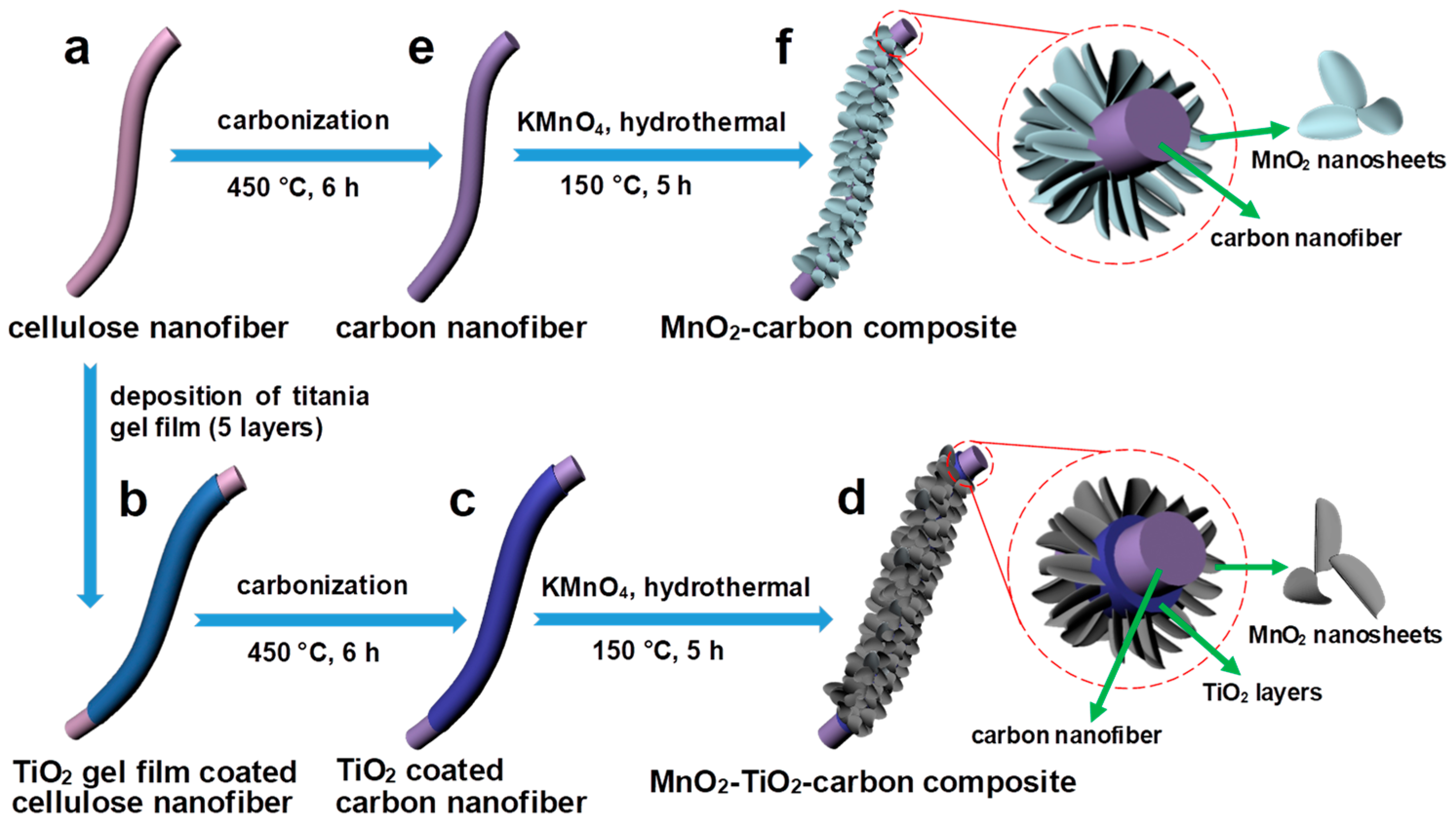
2.2. Fabrication of the Nanofibrous MnO2-TiO2-Carbon and MnO2-Carbon Composites

In a representative procedure, 5-layer titania gel film was deposited onto the surface of cellulose nanofibers from bulk quantitative filter paper using a surface sol–gel method (Scheme 1a,b), which was followed by carbonization of the as-synthesized TiO2 gel film by precoating the cellulose nanofiber in an Ar atmosphere at 450 °C for 6 h to obtain the TiO2-carbon nanocomposite (Scheme 1c) [25]. Subsequently, 20.0 mg of TiO2-carbon material was added into 20 mL DI water with sonification for 1.5 h, in order to control the MnO2 content in the resultant composite. Various weights of KMnO4 (30 and 25 mg) were then added and stirred under the ambient temperature for 5 h. Finally, the two as-obtained violet mixtures were transferred to 50-mL Teflon-lined autoclaves (Zhongnuo Instrument Co., Ltd., Xi’an, China), respectively, and further heated in a muffle furnace (Jinghong Experimental Equipment Co., Ltd., Shangai, China) at 150 °C for 5 h. After cooling to an ambient temperature, the brownish products were rinsed with DI water and absolute ethanol 3–4 times, and were dried further overnight in an electric vacuum oven (80 °C, Yiheng Scientific Instrument Co., Ltd., Shangai, China) (Scheme 1d). As verified by thermal gravimetric analyses (TGA), the contents of MnO2 in the MnO2-TiO2-carbon composites were measured to be 47.28 wt % and 37.81 wt %, respectively. The corresponding composites were designated as MnO2-TiO2-carbon-47.28% and MnO2-TiO2-carbon-37.81%, respectively. As for the control experiment, MnO2-carbon materials with varying MnO2 contents were fabricated under same conditions without a pre-deposited titania gel layer (Scheme 1e,f). The TGA measurements showed that the MnO2 contents in the MnO2-carbon composite were 40.15 wt % and 33.30 wt % when the addition of KMnO4 was 30 and 25 mg, respectively. The obtained composites were designated as MnO2-carbon-40.15% and MnO2-carbon-33.30%, respectively. The MnO2 nanoparticles (MnO2-NPs) were fabricated by the addition of 0.2 g KMnO4 and 0.2 mL H2SO4 (95 wt %) to 25 mL DI water to form a precursor, and followed by hydrothermal reaction at 150 °C for 4 h.

2.3. Characterizations

A small amount of specimen was dispersed in absolute ethanol followed by ultrasonication for 60 s; then, the suspensions were dropped onto aluminum foil for field emission scanning electron microscopy (FE-SEM) tests on a Hitachi SU-8010 (HITACHI, Tokyo, Japan) instrument with an acceleration voltage of 5.0 kV. In the meantime, the resultant mixtures were placed on a copper grid for transmission electron microscopy (TEM) observations on a Hitachi HT-7700 (HITACHI, Tokyo, Japan) tool with an acceleration voltage of 100 kV. High-resolution transmission electron microscopy (HR-TEM) and selected area electron diffraction (SAED) measurements were conducted on a JEM-2100F apparatus (JEOL, Tokyo, Japan) with an acceleration voltage of 300 kV. X-ray diffraction (XRD) measurements were performed on a Philips X’Pert PRO diffractometer (PANalytical B.V., Alemlo, The Netherlands) using Cu (λ = 0.15405 nm) as a radiant source. X-ray photoelectron spectra (XPS) were detected by employing a VG Escalab Mark 2 spectrophotometer (VG Instruments, Manchester, UK) with a MgKα X-ray source (1253.6 eV). High-resolution scans of Mn were performed at 0.2 eV increments (sweep time: 1000 ms eV−1, each region: 30 energy sweeps). The C 1s peak at 284.50 eV was used as a standard for all the XPS peaks. Raman spectra were obtained using a Jobin Yvon LabRam HR UV Raman spectrometer (HORIBA, Paris, France) with an excitation wavelength of 532 nm. Thermal gravimetric analyses (TGA) were performed on a Mettler Toledo STARe System TGA2 (Mettler Toledo Crop., Zurich, Switzerland) at a heating rate of 10 °C min−1, from room temperature to 800 °C in a nitrogen atmosphere. The specific surface areas of the samples were determined through measurement of the N2 adsorption–desorption isotherms at −196 °C with a Micromeritics ASAP-2020 tool (Micromeritics, Norcross, GA, USA), and the Brunauer–Emmett–Teller (BET) method was applied to compute the surface area and pore volume of the MnO2-TiO2-carbon composites.

2.4. Electrochemical Measurements

The working electrodes were prepared by mixing Super P (10 wt %) and polyvinylidene fluoride binder (PVDF, 10 wt %) with the active material (80 wt %) in N-methyl-2-pyrrolidinone (NMP) solvent. The slurries were uniformly coated onto copper foam and dried in a vacuum oven (80 °C, 12 h); the electrodes were then pressed at 12 atm and the mass loading of the active material was ca. 1.5–2.0 mg for each electrode. Coin-type cells (CR2025, DodoChem, Suzhou, China) were assembled in an argon filled glove box with concentrations of oxygen and water molecules less than 0.1 ppm. A Li metal plate was used as the auxiliary electrode and polypropylene (Celglad 2300, DodoChem, Suzhou, China) film was used as the separator. The electrolyte was composed of 1.0 M LiPF6 in ethylene carbonate (EC), ethyl methyl carbonate (EMC), and dimethyl carbonate (DMC) (EC:EMC:DMC, v:v:v = 1:1:1). Cyclic voltammetry (CV) tests were performed on a CHI760D electrochemical workstation (CH instruments, Shanghai, China) with a scan rate of 0.1 mV s−1 and voltage window of 0.01–3.0 V. Galvanostatic charge/discharge performances were tested using a Neware battery testing system (Neware Technology Co., Ltd., Shenzhen, China) in the voltage range from 0.01 to 3.0 V (Li/Li+) at ambient temperature. Electrochemical impedance spectra (EIS) measurements were recorded in the frequency range of 100 kHz to 0.01 Hz. The structural stability of the electrode composites after 200 charge/discharge cycles was confirmed via electron microscope observations.

3. Results and Discussion

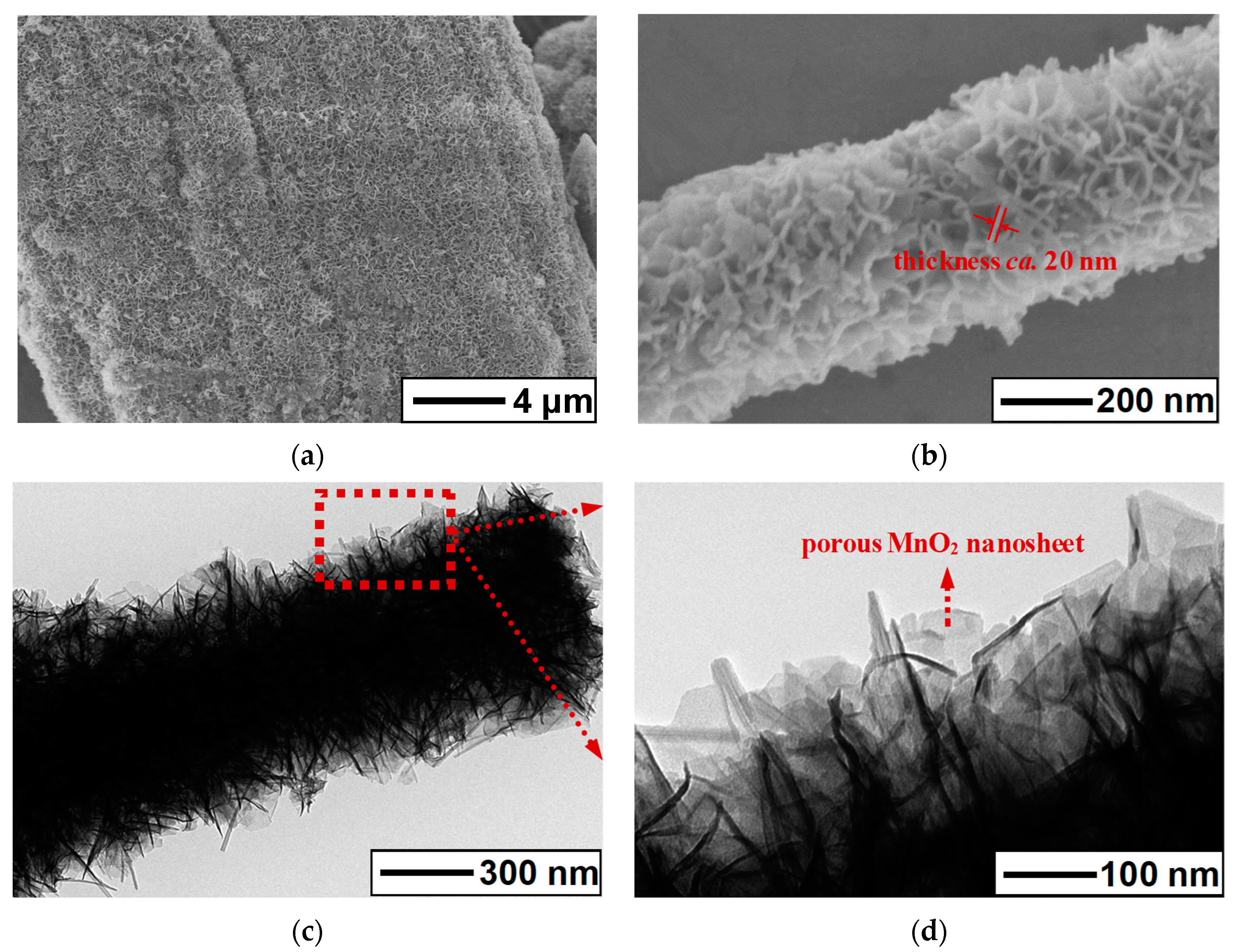
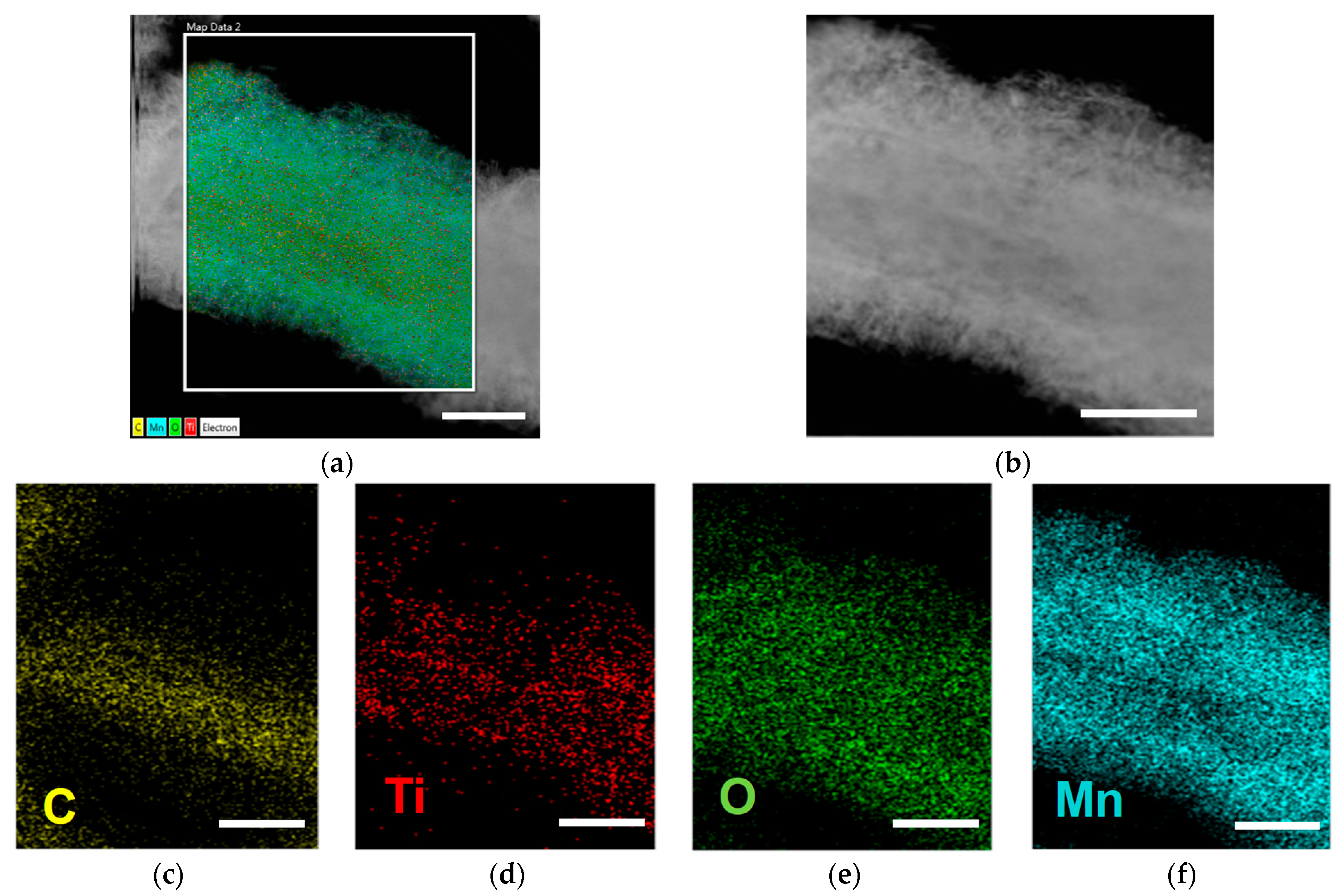
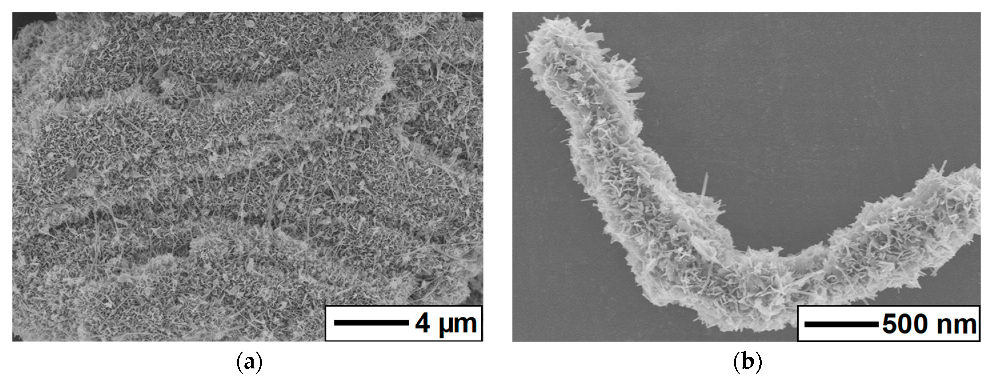
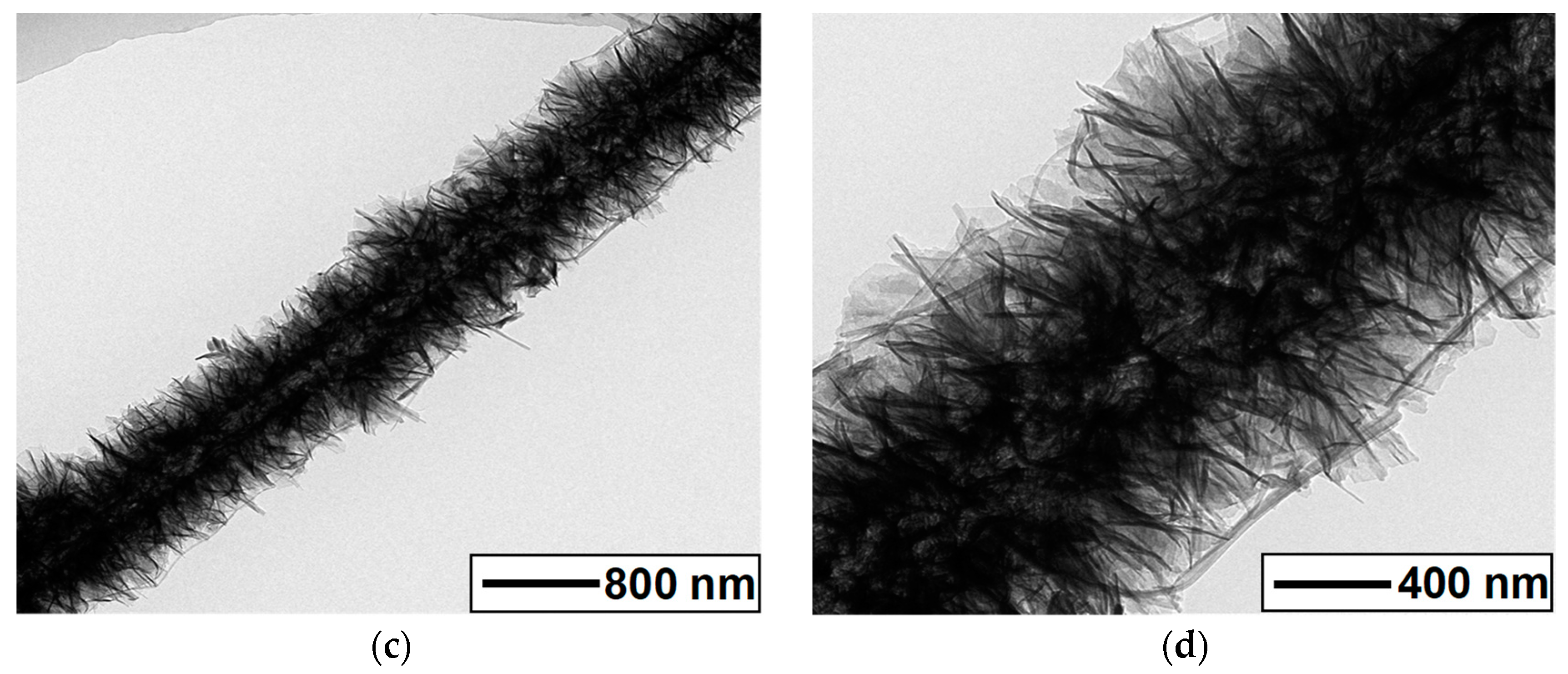
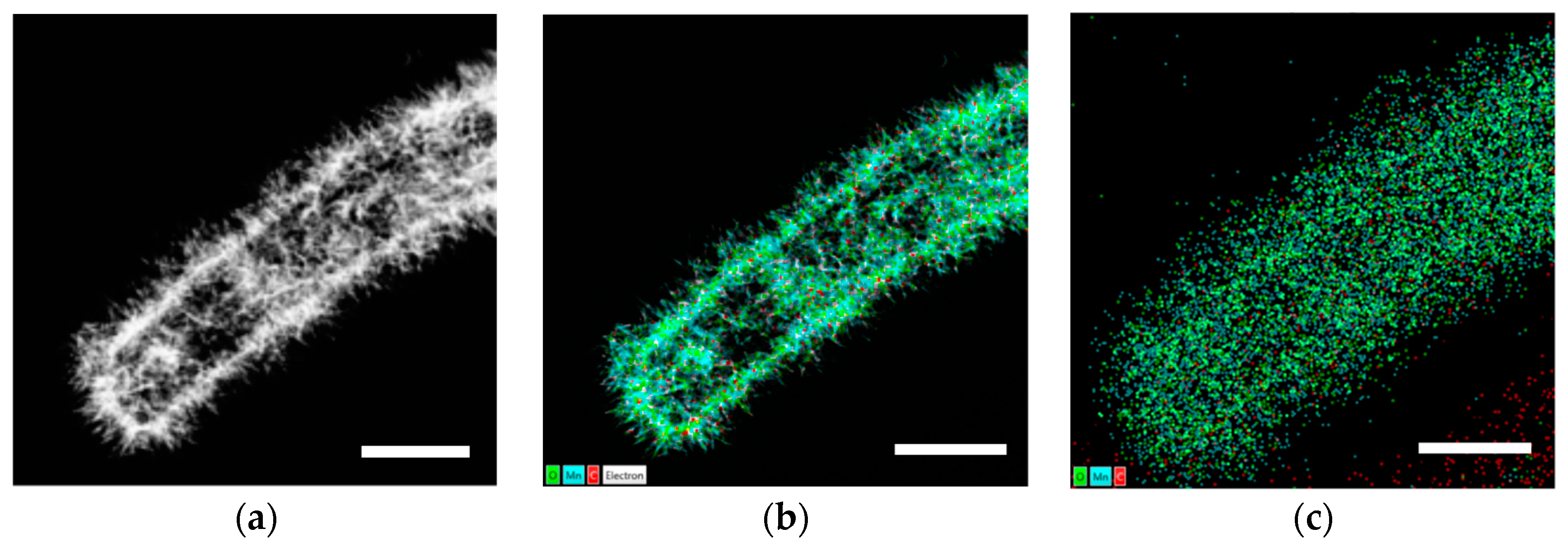
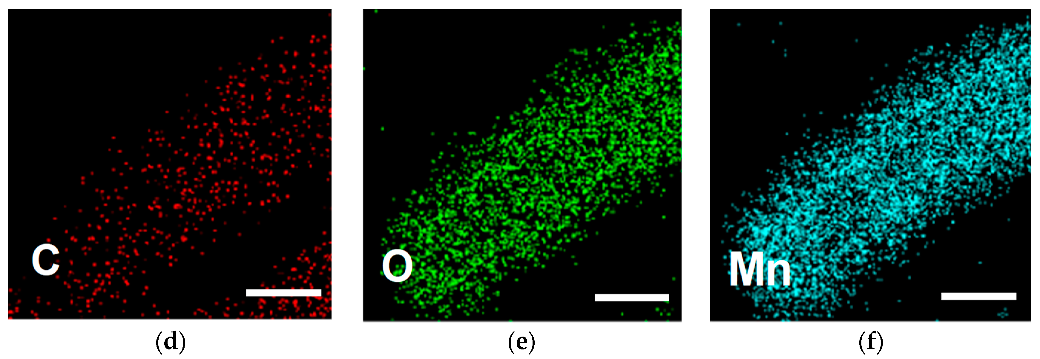
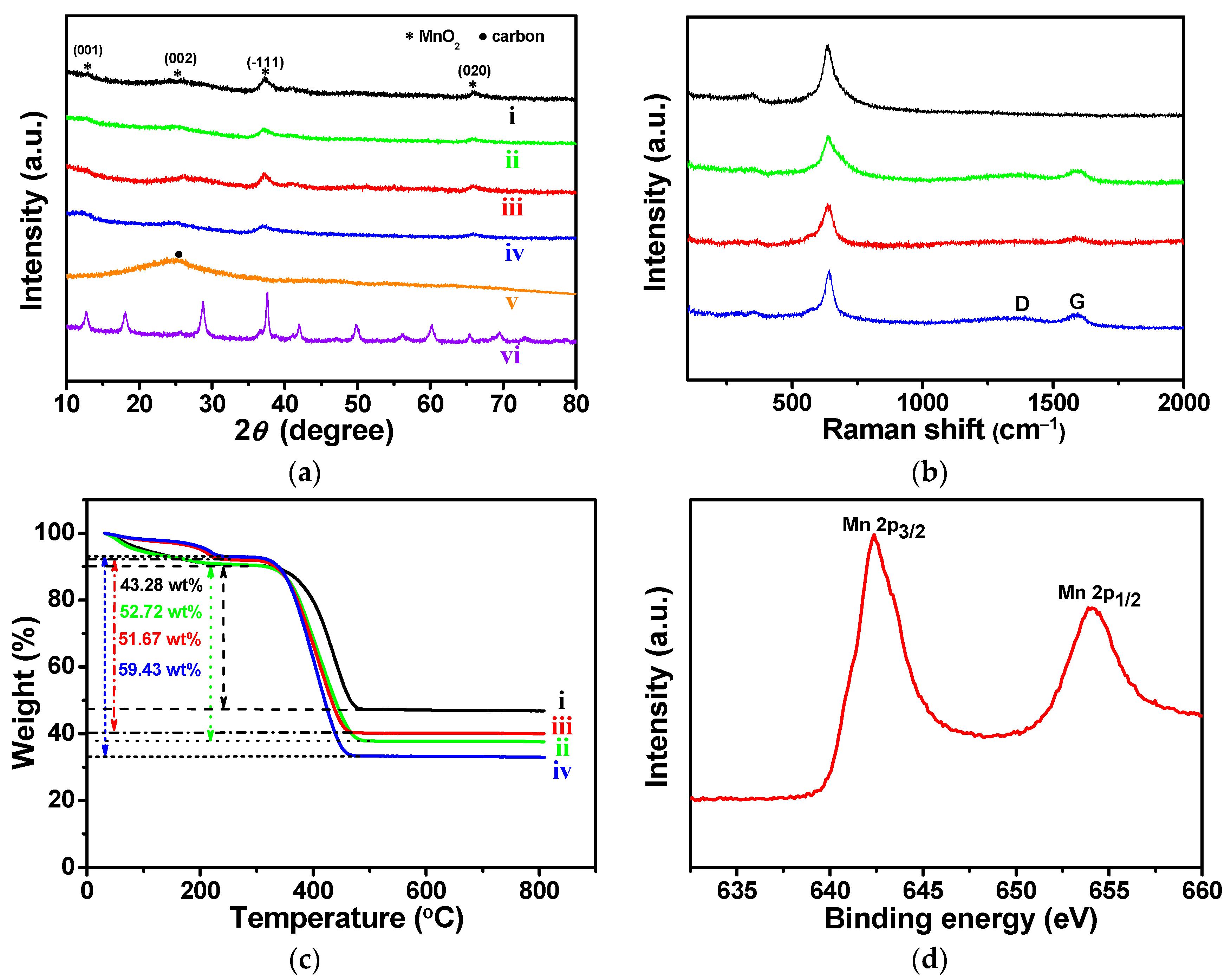
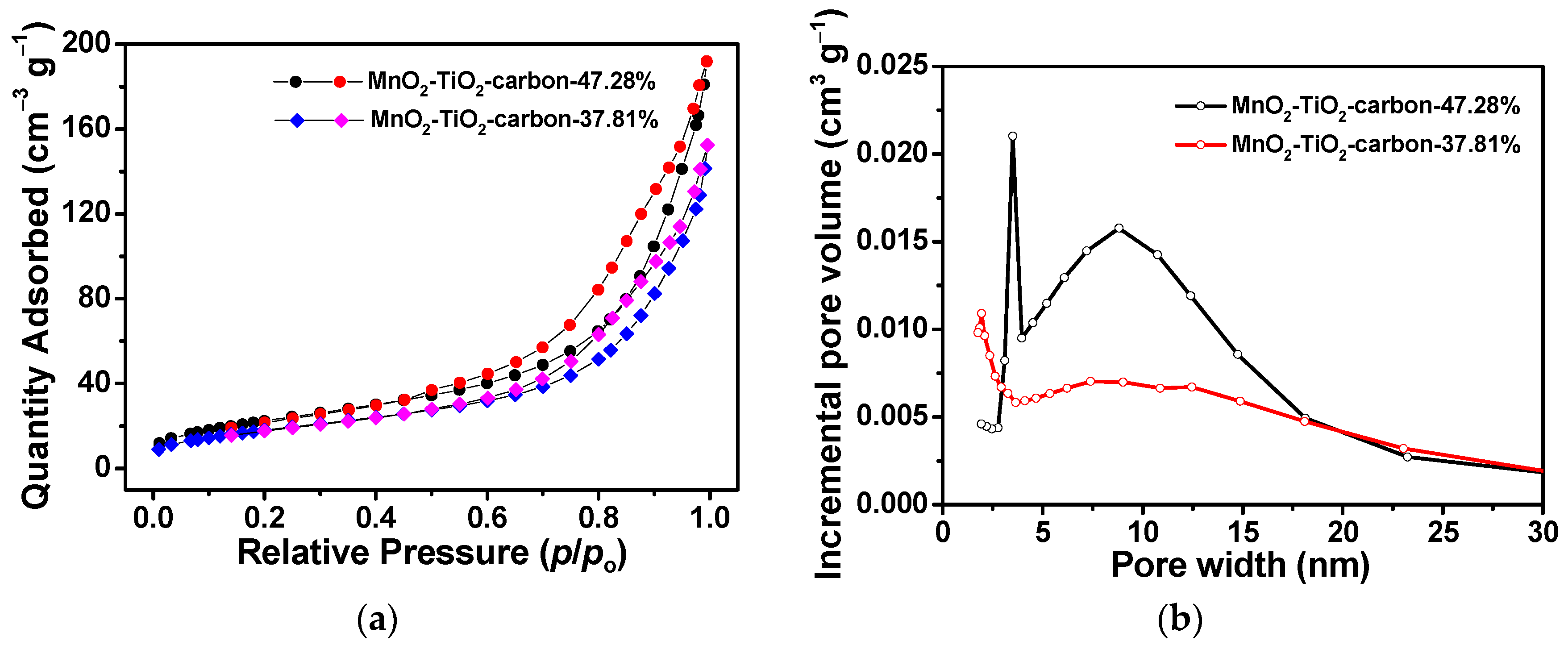
3.1. Structural Characterizations of the MnO2-TiO2-Carbon and MnO2-Carbon Composites

As illustrated in Scheme 1, the MnO2-based carbon composites were obtained by utilizing natural cellulosic substances (e.g., common commercial filter paper) as both the scaffolds and carbon sources. The MnO2 nanosheets were uniformly immobilized on the surfaces of the ultrathin TiO2-coated carbon nanofibers or on the nanofibrous carbon to acquire MnO2-TiO2-carbon (Scheme 1a–d) and MnO2-carbon composites (Scheme 1a–f). The resultant materials with varied MnO2 contents were denoted as MnO2-TiO2-carbon-47.28%, MnO2-TiO2-carbon-37.81%, MnO2-carbon-40.15%, and MnO2-carbon-33.30%, respectively.
The morphology and structure properties of the MnO2-TiO2-carbon-47.28% composite are shown in Figure 1. It can be clearly seen that the composite is composed of interconnected microfibers, and each microfiber consist of nanofiber assemblies with a diameter range from tens of to several hundred nanometers (Figure 1a). The three-dimensional network structures of the nanocomposite were perfectly inherited from the original cellulose substances, and the closely-packed MnO2 sheets (thickness ca. 20 nm) were evenly immobilized on the surfaces of the titania-coated carbon nanofibers (Figure 1b). The diameter of an individual MnO2-TiO2-carbon-47.28% nanofiber isolated from the nanofiber assemblies was ca. 400 nm (Figure 1c). A high-magnification TEM image (Figure 1d) of the composite nanofiber shows MnO2 nanosheets with a pore structure that was formed from the evaporation of the H2O molecules.
The selected area electron diffraction (SAED) of an individual MnO2-TiO2-carbon-47.28% nanofiber and the relevant EDS elemental mapping of carbon (C), titanium (Ti), oxygen (O), manganese (Mn) are shown in Figure 2. It was observed that C appears in the central area of the composite nanofiber, whereas the distribution zones of Mn and O were comparable and wider than those of Ti and C. This implies that the MnO2 nanosheets were uniformly immobilized on the surface of the titania-coated carbon nanofibers. In comparison, the multilevel structures of original filter paper were perfectly sustained by the resultant MnO2-TiO2-carbon-37.81% composite (Figure S1, Supplementary Materials). The densely loaded MnO2 nanosheets (thickness ca. 15 nm) were anchored to the surface of the titania-carbon nanofibers, and MnO2 nanorods with a diameter of around 20 nm were connected by the adjacent MnO2-TiO2-carbon-37.81% composite nanofibers to construct three-dimensional cross-linked network structures. When these two composites were tested as anode materials for LIBs, the MnO2-TiO2-carbon-47.28% composite showed a higher electrochemical performance than the sample MnO2-TiO2-carbon-37.81%. This was attributed to the stronger binding force between the well-organized MnO2 nanosheets and the titania coating layer in MnO2-TiO2-carbon-47.28%. Hence, the large volume change and pulverization of the MnO2 nanosheets were significantly alleviated.
Figure 3 shows SEM and TEM images of the MnO2-carbon-40.15% composite, extensive MnO2 nanosheets and a few MnO2 nanorods grew on the surfaces of the nanofibrous carbon (Figure 3a,b). The immobilized MnO2 nanosheets with a porous structure can obviously be seen in Figure 3c,d. In contrast, the density of the MnO2 nanosheets in MnO2-carbon-40.15% was lower than that of the MnO2-TiO2-carbon-47.28% composite because the titania film provided more active sites for the growth of MnOOH, which resulted in the well-organized growth of MnO2 nanosheets of smaller sizes [32]. The original multilevel morphology of the structures can still be observed in the MnO2-carbon-33.30% materials (Figure S2), showing that the closely packed MnO2 nanosheets are immobilized on the surface of carbon nanofibers, crosslinked MnO2 nanorods are intertwined among the MnO2-carbon-33.30% nanofibers surfaces. However, the as-fabricated MnO2-NPs with a mean diameter of ca. 30 nm and length of hundreds of nanometers tended to aggregate (Figure S3).
Energy-dispersive X-ray spectrometry (EDS) mapping test results are exhibited in Figure 4 to further verify the structural and elemental construction of the MnO2-carbon-40.15% materials. The uniformly distributions of Mn and O elements indicate the successful immobilization of MnO2 onto the surface of the carbon nanofiber (Figure 4d–f). The growth of MnO2 in the MnO2-TiO2-carbon and MnO2-carbon composites are based on the following reaction [33]:
4MnO4 + 3C + H2O = 4MnO2 + CO32− + 2HCO3
In this process, the carbon can easily react with KMnO4 in solutions and form a strong adhesion force between the MnO2 sheets and the titania-coated carbon or the carbon nanofibers. The content of MnO2 in the MnO2-TiO2-carbon-47.28% exceeded that of the MnO2-carbon-40.15% composite, which was due to the protective effects of the titania precoating layer. The interconnected carbon nanofibers derived from the natural cellulose substance served as a conductive matrix to enhance electron transportation and shorten the pathway of Li+ during cycling. In addition, the ultrathin TiO2 coating layer well facilitated the growth of MnO2 nanosheets on the surface of TiO2-carbon nanofibers through a redox reaction, as mentioned above.
To determine the phase structure of the composite materials, Figure 5a shows the X-ray diffraction results of the corresponding samples; the major peaks presented in the MnO2-TiO2-carbon-47.28%, 37.81%, and MnO2-carbon-40.15%, 33.30% materials are indexed to the (001), (002), (−111) and (020) planes of α-MnO2 crystal (JCPDS#. 80-1098) [34]. A broad diffraction peak situated at approximately 26° corresponded to the (002) plane of graphitic carbon in the TiO2-carbon composite, and the relatively weak peak intensity of the carbon reflection was seen in MnO2-based carbon composites [35]. The XRD pattern of the MnO2-NPs was attributed to the monoclinic potassium birnessite, which was composed of 2D edge-shared MnO6 octahedral layers with K+ and H2O molecules contained in the interlayer space [4].
The structure features of the MnO2-TiO2-carbon composites were further verified using Raman spectra, as shown in Figure 5b. A broad peak located around 650 cm−1 was assigned to the Mn-O stretching vibration of the MnO6 octahedra [33]. Two weak peaks positioned at 1350 and 1590 cm−1 were ascribed to the D- and G-bands of the carbon materials, respectively [36]. The corresponding peak intensities of the D- and G-bands of carbon components became lower with the increasing content of MnO2 nanosheets in the MnO2-TiO2-carbon and MnO2-carbon composites, which was due to the depletion of carbon during the formation of the MnO2 nanosheets (Equation (1)). However, the TiO2 peaks could not be clearly identified in the MnO2-TiO2-carbon-47.28% and 37.81% materials because there was less TiO2 content, and they are almost completely covered by intensively immobilized MnO2 nanosheets [32].
The carbon and MnO2 contents in the resultant MnO2-based carbon composites were evaluated using TGA measurements. As exhibited in Figure 5c, below 250 °C, about 8–10 wt % weight loss of the samples occurred due to the evaporation of water and other small molecules. Rapid weight losses during the oxidation of the carbon nanofibers between 300–500 °C in air were calculated as 43.28, 52.72, 51.67 and 59.43 wt % for the MnO2-TiO2-carbon-47.28%, 37.81% and MnO2-carbon-40.15%, 33.30%, respectively. Moreover, the contents of TiO2 were too low and could be ignored in the two titania-based composites. Thus, the contents of MnO2 contained in the MnO2-TiO2-carbon-47.28%, 37.81% and MnO2-carbon-40.15%, 33.30% are 47.28, 37.81, 40.15 and 33.30 wt %, respectively.
The Mn 2p peaks from the XPS spectrum were tested to study the valence state of Mn in the MnO2-TiO2-carbon-47.28% composite, and the results are shown in Figure 5d. Two peaks centered at 653.8 and 642.1 eV were indexed to Mn 2p1/2 and Mn 2p3/2, respectively. The energy separation value of 11.7 eV is well in accordance with the known data for MnO2 [37]. Moreover, the oxidation state of Mn in the MnO2-TiO2-carbon-37.81% composite showed the similar results to those of MnO2-TiO2-carbon-47.28% composite, which demonstrated the existence of MnO2 in the sample (Figure S4).
Figure 6 displays the N2 adsorption–desorption isotherms and the pore-size distribution curves of the MnO2-TiO2-carbon-47.28%, -37.81% composites. Both of the composite materials clearly show type IV isotherms with a type H3 hysteresis loop, indicating the existence of mesopores in the composites [38]. The specific surface areas of the MnO2-TiO2-carbon-47.28% and 37.81% were 83.2 and 67.1 m2 g−1 (Figure 6a), and the pore volumes of the two composites were calculated to be 0.299 and 0.238 cm3 g−1, respectively. A mesoporous structure was observed for the MnO2-TiO2-carbon-47.28% composite with average sizes of 3.5 and 8.8 nm (Figure 6b). However, the average pore size of the MnO2-TiO2-carbon-37.81% was measured to be 1.9 nm. Due to the larger specific surface area and the mesoporous structure of the MnO2-TiO2-carbon-47.28% composite, this material could supply sufficient active sites and accelerate electron transportation during Li+ insertion/extraction processes, thus leading to better electrochemical performance of the electrode material. Hence, it is concluded that the composite with a larger pore volume and higher specific surface area is able to deliver a high specific capacity and long cycling life during the charge/discharge processes [31].

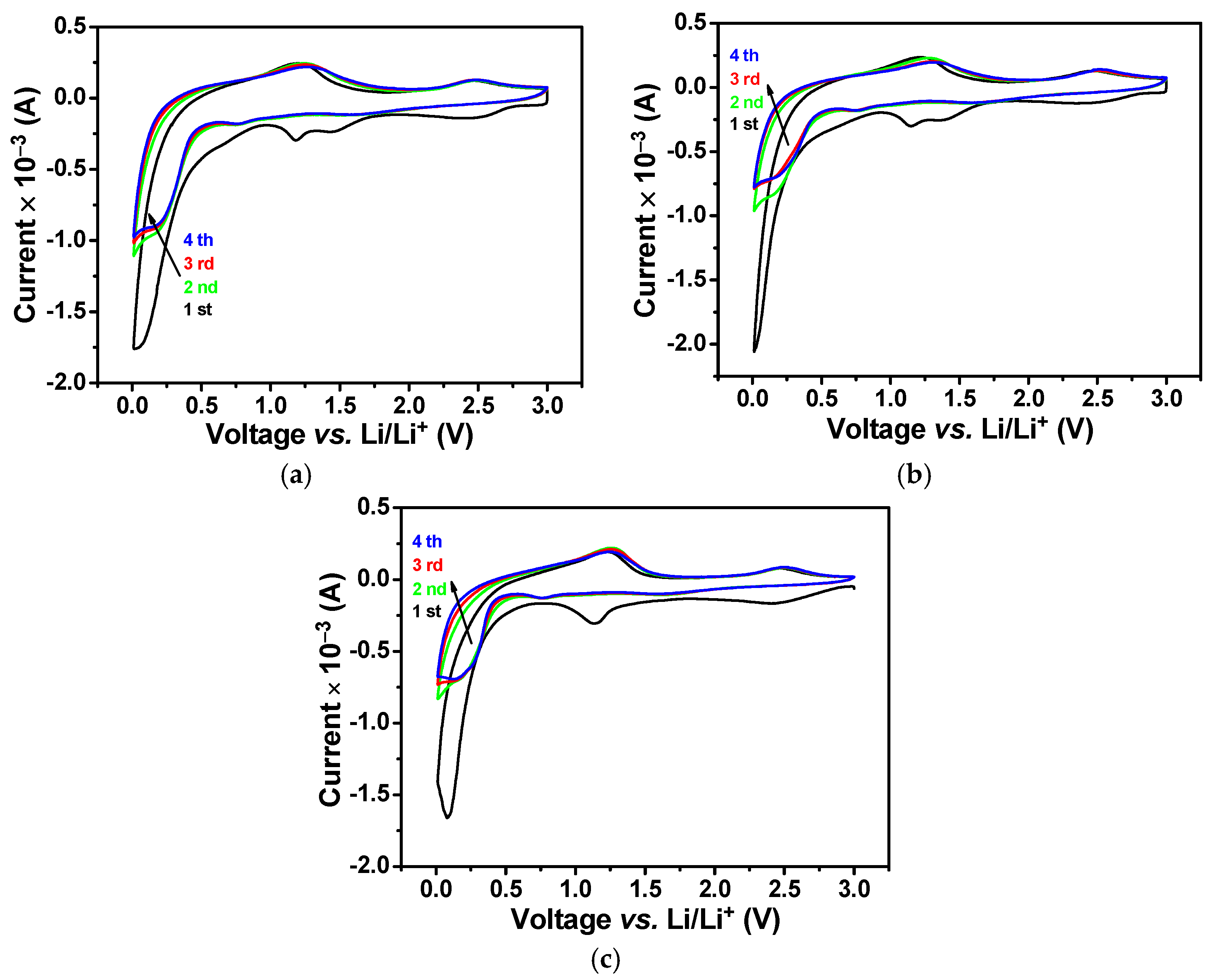
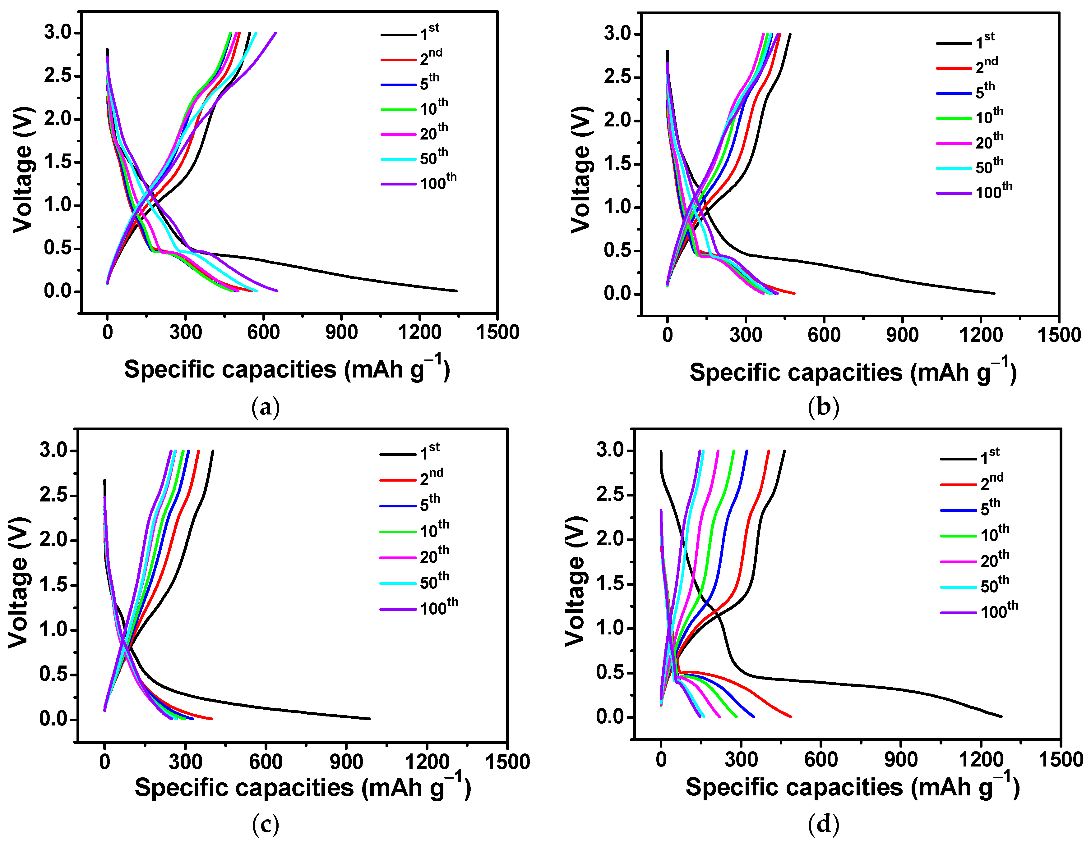
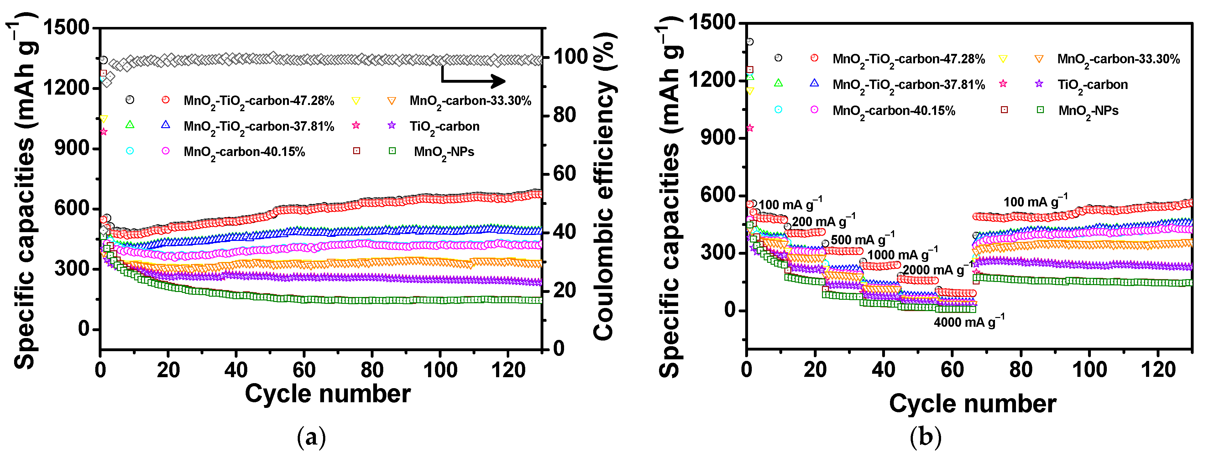
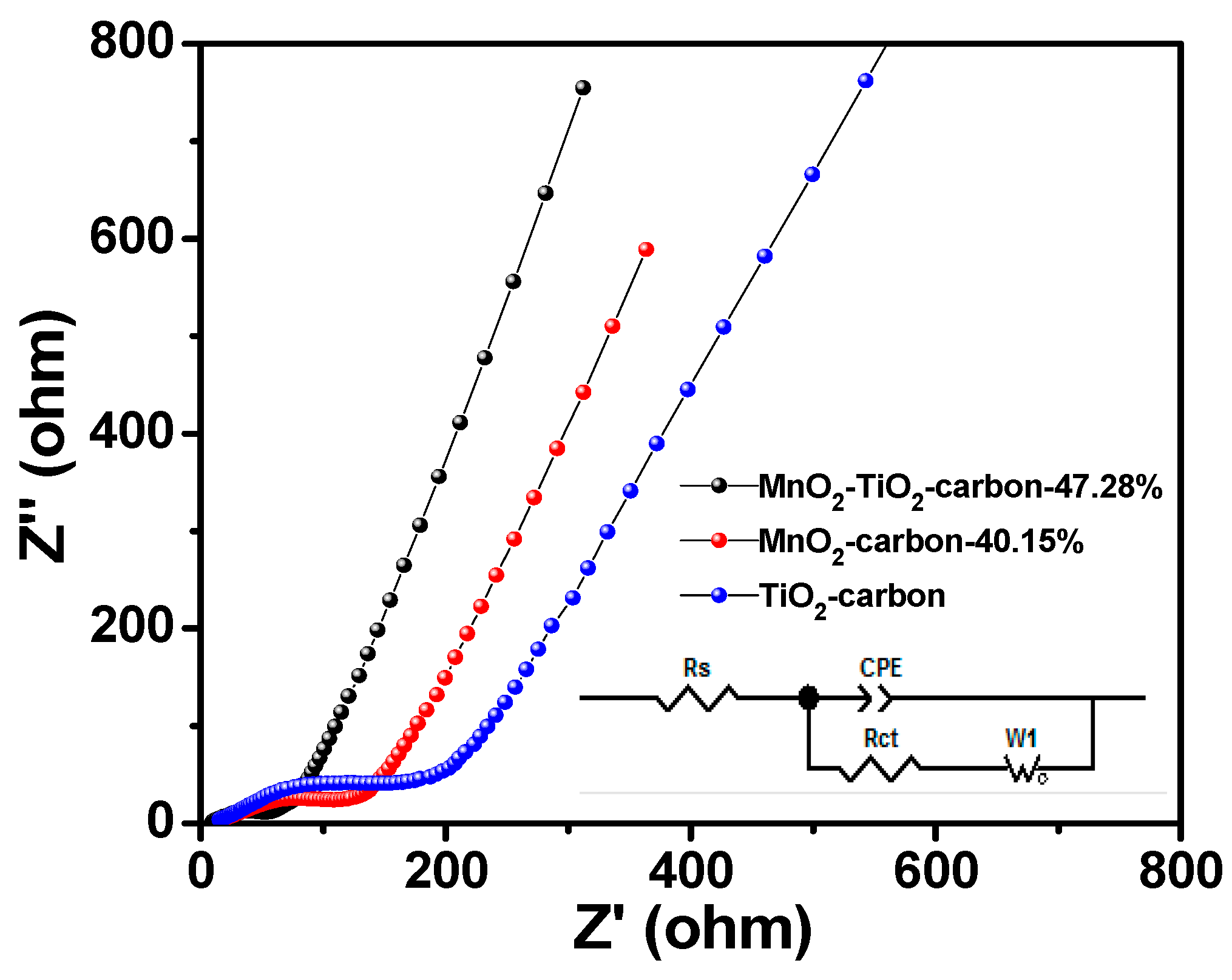
3.2. Electrochemical Study of the MnO2-TiO2-Carbon and MnO2-Carbon Composites

The electrochemical performances of the nanofibrous MnO2-TiO2-carbon composites employed as anodic materials for LIBs were tested to evaluate the kinetics of Li+ intercalation/deintercalation processes. Figure 7 shows the cyclic voltammetric (CV) curves of MnO2-TiO2-carbon-47.28%, MnO2-carbon-40.15% and MnO2-NPs electrodes during charge/discharge processes in the voltage range from 0.01 to 3.0 V with a scan rate of 0.2 mV s−1. In the initial cathodic curves of both MnO2-TiO2-carbon-47.28% and MnO2-carbon-40.15% electrodes (Figure 7a,b), a broad peak centered at 0.1 V was attributed to the formation of a solid–electrolyte interface (SEI) layer and a reduction of Mn2+ to metallic Mn0 [16], and two mild peaks at 1.17 and 2.46 V corresponded to the reduction of MnO2 to Mn2+ and the decomposition of electrolytes [19,39]. The whole discharge process was calculated as Equation (2):
MnO2 + 4Li+ + 4e → 2Li2O + Mn
Two oxidation peaks at 1.24 and 2.45 V were observed in the first anodic curve, which were attributed to the oxidations of Mn0 to Mn2+ and Mn2+ to Mn4+, respectively [39]. The whole charge process was calculated as Equation (3):
2Li2O + Mn → MnO2 + 4Li+ + 4e
In the next cycles, the reduction peak at 0.1 V and the oxidation peak at 1.18 V shifted to 0.15 and 1.24 V, respectively. The distinct shifts in the subsequent cycles were attributed to the structural changes and reconstitutions initiated by the formation of amorphous Li2O and Mn0 [40,41,42,43]. For MnO2-NPs, an acuminated cathodic peak centered at 0.08 V and a relatively weaker peak at 1.14 V in the first charge curve were ascribed to the formation of a SEI layer and the reduction of MnO2 to Mn (Figure 7c). Two oxidation peaks at 1.24 and 2.47 V were noticed in the charge curves, which meant a two-step electrochemical reaction [19]. The weak redox peaks in the first cycles of the three anodes located at 0.67 and 2.47 V were attribute to the conversion reaction between the Cu metal (copper foam) and CuO, and the Cu2O hybrid nanocomposite, and the cathodic peak shift to 0.76 V in subsequent cycles [44]. The peak intensities of the CV curves of MnO2-carbon-40.15% and MnO2-NPs decreased over the next three charge/discharge cycles, indicating fading of the irreversible capacity of the first cycle. In comparison, the peak intensities of the curves (Figure 7a) overlapped well in the next three cycles, implying excellent electrochemical reversibility and the structural stability of the MnO2-TiO2-carbon-47.28% anode. The ultra-thin titania film coating layer served as a protective barrier during the reaction of MnO4 with carbon nanofiber and led to the uniform immobilization of MnO2 nanosheets with higher contents, which was well in accordance with the TGA measurements. The CV curves of the MnO2-TiO2-carbon-37.81% and MnO2-carbon-33.30% anodes showed similar peak shifts as MnO2-TiO2-carbon-47.28% and MnO2-carbon-40.15%, implying analogous Li+ insertion/extraction processes (Figure S5). However, the intensities of the charge/discharge curves decreased quickly in subsequent cycles, indicating that the fast irreversible capacity was fading and that there was poor cycling stability.
The charge/discharge curves of the MnO2-TiO2-carbon-47.28%, MnO2-carbon-40.15%, TiO2-carbon nanofiber and MnO2-NPs electrodes are shown in Figure 8. The first discharge and charge capacities of MnO2-TiO2-carbon-47.28% composite were 1341 and 547 mAh g−1 (Figure 8a), respectively, showing a Coulombic efficiency of 41%. The huge irreversible capacity degradation was due to the formation of a SEI layer that covered the surface of the electrode material [45]. In following cycles, the charge/discharge capacities of the electrode materials were reduced from 556 to 489 mAh g−1 as they cycled to the 5th cycle. The Coulombic efficiency increased to 98% at the 10th cycle, the cycling capacities continued to slowly rise and finally reached a constant capacity of 652 mAh g−1 by the 100th cycle. A flat voltage plateau at around 0.4–0.5 V during the discharge process indicated the reduction of MnO2 to Mn in one step. However, a sharp plateau and a short plateau were observed in following discharge processed, implying two steps of reduction of Li with MnO2. Two charge plateaus at around 1.0–1.3 V and 2.2–2.5 V demonstrated the oxidation of Mn0 in two steps [33,46]. These results are well in accordance with the CV measurements. As a comparison, the MnO2-TiO2-carbon-37.81% electrode exhibited discharge and charge capacities of 1259 and 477 mAh g−1, respectively, resulting in a Coulombic efficiency of 37.9%. Moreover, the discharge capacity fell to 407 mAh g−1 after 10 cycles and slowly increased to a stable capacity of 494 mAh g−1 by the 100th cycle (Figure S6a). The MnO2-TiO2-carbon-47.28% composite showed better electrochemical performance than MnO2-TiO2-carbon-37.81%, and its charge/discharge plateaus were longer, which implied well-organized MnO2 nanosheets with higher contents in the composite-47.28% electrode that furnished adequate active sites for the Li+ and electron transport. The discharge capacities of MnO2-carbon-40.15% electrodes dropped rapidly from 1251 to 367 mAh g−1 when cycled for 20 cycles (Figure 8b). The large capacity loss of the MnO2-carbon-40.15% electrode was related to the weak adhesion between the MnO2 nanosheets and the carbon nanofiber, thus leading to the exfoliation and structure destruction of MnO2 during cycling. As for the MnO2-carbon-33.30% electrodes, the primary discharge and charge capacities of the composite were 1053 and 386 mAh g−1, respectively, presenting a Coulombic efficiency of 36.7% (Figure S6b). The severe capacity degradation of the MnO2-carbon-33.30% was attributed to the weak adhesion between the MnO2 nanosheets and carbon nanofibers that led to the debonding of MnO2 nanosheets from the carbon nanofibers. These exfoliated MnO2 nanosheets may have suffered from huge volume changes and lost their effective contact with the electrolyte, resulting in the poor electrochemical performance of the electrodes [34]. The discharge capacity the TiO2-carbon nanofibers decreased from 985 to 249 mAh g−1 after 100 cycles (Figure 8c). This further demonstrated that the immobilized MnO2 nanosheets significantly boosted the capacity of MnO2-TiO2-carbon composites and improved the structure stability of the electrodes during the Li+ intercalation/deintercalation processes. However, the initial discharge and charge capacities of MnO2-NPs were 1276 and 464 mAh g−1, respectively, giving a Coulombic efficiency of 36.4% (Figure 8d), and the capacity steadily decreased to 146 mAh g−1 after 100 cycles. The great irreversible capacity loss was ascribed to the aggregation and pulverization of MnO2-NPs during the repeated charge/discharge processes, thus leading to poor cycling stability as well as a low rate capability.
The cycling performance of the MnO2-TiO2-carbon-47.28%, 37.81%, MnO2-carbon-40.15%, 33.30%, TiO2-carbon nanofibers and MnO2-NPs are shown in Figure 9a. For the MnO2-TiO2-carbon-47.28% composite, the capacity dropped rapidly in the first three cycles and thereafter increased gradually after 10 cycles, reaching a capacity of 677 mAh g−1 by the 130th cycle, delivering a Coulombic efficiency of over 99%. The reason for the improvement in capacity has been elucidated for many transition metal oxides, which might be attributed to the reversible growth of the polymeric gel-like film and the activation of electrode materials during Li+ insertion/extraction processes [46,47,48]. A variety of reported MnO2 nanostructures and MnO2-based composites have turned out to be good anode materials for LIBs [18,33,34,49,50,51]. The present fabricated bio-inspired nanofibrous MnO2-TiO2-carbon-47.28% composite showed comparable or better capacity capability when tested at identical current densities (Table 1). These enhancements were ascribed to the three-dimensional reticular structure and the high surface-to-volume ratio of the composite derived from the natural cellulosic substances, which effectively alleviated the large volume expansion and exfoliation of the MnO2 nanosheets. Therefore, the MnO2-TiO2-carbon-47.28% electrode material exhibited superior electrochemical performance during cycling. However, the MnO2-TiO2-carbon-37.81%, with a relative lower content of MnO2, showed a stable capacity of 491 mAh g−1 after 130 cycles, implying that the higher MnO2 loading is capable of contributing a larger capacity to the composites. As a comparison, the capacity of MnO2-carbon-40.15% faded sharply in the initial 20 cycles and a steady capacity of 425 mAh g−1 was obtained after 130 charge/discharge cycles. The capacity difference among the MnO2-TiO2-carbon and MnO2-carbon-40.15% composites suggested that the ultrathin titania film pre-coated on the surface of the carbon nanofibers plays an important role in improving the stability of the cycling performance of the electrodes. It was found that the TiO2 coating layer facilitated the growth of well-organized MnO2 nanosheets with a higher content in the case of the KMnO4 precursor with a high concentration is used. While the discharge capacity of MnO2-carbon-33.30% dropped from 1053 to 335 mAh g−1 after 130 cycles. This further illustrated that MnO2 nanosheets were likely to be peeled off from the composite and tended to aggregate during Li/Li+ processes, thus leading to severe capacity fading. The TiO2-carbon nanofibers delivered a fast capacity loss in the first 20 cycles and slowly decreased to 235 mAh g−1 by the 130th cycle, corresponding to a 58.5% retention of the first charge capacity. The large irreversible capacity degradation of the electrode was ascribed to the formation of a SEI layer. For the MnO2-NPs, a sudden capacity loss was observed in the initial 30 cycles and then slowly reduced to 145 mAh g−1 at the 130th cycle, resulting in a capacity retention of 29.8% for the second discharge capacity. This phenomenon can be explained by the huge volume expansion and aggregation of MnO2-NPs during the electrochemical processes.
To evaluate the capacity contribution of the MnO2 component to MnO2-TiO2-carbon-47.28%, 37.81% and MnO2-carbon-40.15%, 33.30% composites, the capacities of MnO2 were calculated using the following Equation (4):
C   ( total ) = C ( TiO 2 / carbon )   ×   W ( carbon )   wt % + C ( MnO 2 ) ×   W ( MnO 2 )   wt %
Since the TiO2 in the MnO2-TiO2-carbon composite was too low and could be ignored, the separated capacity contribution of titania and carbon constituents in the electrodes were calculated as the whole capacity of the TiO2-carbon. The results are listed in Table 2, where the contributed specific capacities of MnO2 in the MnO2-TiO2-carbon-47.28%, 37.81%, MnO2-carbon-40.15%, 33.30% electrodes were 1169.9, 912.5, 708.2, 535.3 mAh g−1, respectively. The contribution percentages of MnO2 were equivalent to 95.1%, 74.2%, 57.6%, and 43.5% of the theoretical capacity (1230 mAh g−1), respectively. Significant improvements to the contributing capacity and percentage of MnO2 in the MnO2-TiO2-carbon-47.28% electrode were ascribed to its three-dimensionally interwoven structures with its large specific area, which enabled faster Li+ and electron transport during the electrochemical processes. Moreover, the mesoporous structure with a higher content of MnO2 nanosheets in the composite made a large contribution to the enhancement of the capacity. Therefore, the MnO2-TiO2-carbon-47.28% composite showed superior cycling stability and a high specific capacity when compared with the other three MnO2-based counterparts.
To further investigate the electrochemical superiority of the MnO2-TiO2-carbon-47.28% composite, the rate performances of the composite electrodes at varied current rates are shown in Figure 9b. The MnO2-TiO2-carbon-47.28% electrode delivered discharge-specific capacities of 491, 406, 312, 232, 158, and 94 mAh g−1 with current densities increasing from 100, 200, 500, 1000, 2000, and 4000 mA g−1, respectively. When the current rate was set back to 100 mA g−1, a reversible capacity of 493 mAh g−1 was obtained and successively increased to 560 mAh g−1, implying the favorable rate capabilities of the electrode. In the meantime, the rate capability of MnO2-TiO2-carbon-37.81% was slightly higher than that of the MnO2-carbon-40.15%, and the discharge capacities of composite-37.81% were 392, 319, 212, 132, 73, and 44 mAh g−1 at current rates of 100, 200, 500, 1000, 2000, and 4000 mA g−1, respectively. However, the specific capacities of the MnO2-carbon-40.15% electrode were 376, 313, 194, 120, 61, and 41 mAh g−1 at comparable current densities for composite-37.81%. Though the content of MnO2 in the MnO2-TiO2-carbon-37.81% was lower than that of MnO2-carbon-40.15%, the composite-37.81% still displayed a better rate capability than composite-40.15%. It was concluded that the structural stability of the composite and the strong adhesion of MnO2 nanosheets to the titania film pre-coated carbon nanofibers greatly prevented the exfoliation and pulverization of MnO2 in MnO2-TiO2-carbon-37.81%, and led to a superior rate performance. The MnO2-carbon-33.30% anode showed lower specific capacities of 368, 281, 184, 115, 56, 37, and 330 mAh g−1 at the current rates of 100, 200, 500, 1000, 2000, and 4000 mA g−1, respectively. A reversible capacity of 330 mAh g−1 was retained when the current rate returned to 100 mA g−1. The MnO2-carbon-33.30% electrode exhibited a poor rate performance because of less loading content of MnO2 nanosheets, as well as the weak force between the carbon nanofibers and the MnO2, resulting in the structural destruction of active materials. As for the TiO2-carbon nanofibers, the specific capacities were obviously lower than those of the four MnO2-based samples mentioned above. In comparison, the specific capacity of MnO2-NPs decreased sharply in the initial 10 cycles. When the current rate was set in the range of 500–4000 mA g−1, the capacity reduced to as low as 10 mAh g−1. An irreversible capacity of 167 mAh g−1 was acquired when the cycling density returned to 100 mA g−1. This further demonstrated that the severe volume expansion and aggregation of MnO2-NPs during the Li+ intercalation/deintercalation processes are the main cause of the poor rate capability of the electrode.
To better understand the greatly enhanced electrochemical performances of the MnO2-TiO2-carbon-47.28% electrode, electrochemical impedance spectroscope (EIS) measurements were tested to compare the conductivity of the prepared MnO2-TiO2-carbon-47.28%, MnO2-carbon-40.15% and TiO2-carbon electrodes after 200 repeated cycles. Nyquist plots of the three electrodes as shown in Figure 10 and depict a semicircle in the high frequency zone and an inclined line in the low-frequency region, corresponding to the charge transfer resistance and the Li ion diffusion activity, respectively. The kinetic parameters were evaluated using the equivalent circuit (inset in Figure 10), and Rs represents the internal resistance of the battery, Rct is the charge transfer impedance on the electrode-electrolyte interface, W is the Warburg impedance of Li+ diffusion throughout the active materials, and CPE is the constant phase-angle element [35,52]. The fitting results are listed in Table S1, although the Rs values of the MnO2-TiO2-carbon-47.28%, MnO2-carbon-40.15% and TiO2-carbon electrodes showed little difference, the values of Rct of the three composite electrodes were measured to be 46.32, 155, and 231.7 Ω, respectively. The MnO2-TiO2-carbon-47.28% had the lowest Rs and Rct values; this strongly confirmed that the composite-47.28% had the lowest activation energy and underwent a fast charge transfer reaction, leading to a decrease om the internal resistance of the entire battery. In addition, the structural morphology property of the MnO2-TiO2-carbon-47.28% electrode after 200 charge/discharge cycles was partially retained (Figure S7), demonstrating that structural stabilization was achieved and exhibited excellent cycling stability and reversible rate capability.

4. Conclusions

A cellulose substance-derived nanofibrous MnO2-TiO2-carbon composite was fabricated by immobilizing porous MnO2 nanosheets on the surface of titania-coated carbon nanofibers employing a natural cellulose substance as both the carbon source and the structural matrix. The material, with a large surface area, faithfully inherited the three-dimensional network structures of the original cellulose substances. The MnO2-TiO2-carbon-47.28% composite showed durable cycling performance and stable rate capabilities when employed as anodic materials for LIBs. The improved electrochemical performances of the MnO2-TiO2-carbon-47.28% are attributed to the synergistic effect of the carbon nanofibers, the ultrathin titania coating layer, as well as the high content of MnO2 nanosheets. The internal carbon nanofibers act as a conductive matrix and facilitate Li ion and electron transfer during Li+ insertion/extraction processes. Moreover, the titania layer plays a key role in the higher loading of MnO2 nanosheets, and provides an intermediate interface for the strong adhesion between the carbon nanofiber and MnO2. The mesoporous MnO2 nanosheets with a large theoretical specific capacity contribute to the higher capacity retention. The current method developed for the fabrication of bio-inspired electrode material provides a novel path for the introduction of sophisticated nanoarchitectures into energy-related fields.

Supplementary Materials

The following are available online at https://www.mdpi.com/article/10.3390/ma14123411/s1, Figure S1: Electron micrographs of the nanofibrous MnO2-TiO2-carbon-37.81% composite derived from the natural cellulose substance. (a) SEM image of the MnO2-TiO2-carbon-37.81% composite, (b) SEM image of an individual composite nanofiber isolated from the assemblies, (c,d) the TEM images of an individual MnO2-TiO2-carbon-37.81% nanofiber at different magnifications. Figure S2: Electron micrographs of the nanofibrous MnO2-carbon-33.30% composite derived from a natural cellulose substance. (a) SEM image of the MnO2-carbon-33.30% composite, (b) SEM and (c) TEM images of an individual composite nanofiber. Figure S3: (a,b) SEM and (c,d) TEM micrographs of the MnO2-NPs materials. Figure S4: The high-resolution XPS spectra of Mn 2p regions of the MnO2-TiO2-carbon-37.81% composite. Figure S5: Cyclic voltammetry curves of (a) MnO2-TiO2-carbon-37.81% and (b) MnO2-carbon-33.30% electrodes tested in the initial four charge/discharge cycles at a scan rate of 0.2 mV s−1 between 0.01 and 3 V (vs. Li/Li+). Figure S6. Galvanostatic charge/discharge profiles of (a) MnO2-TiO2-carbon-37.81% and (b) MnO2-carbon-33.30% anode materials measured at a current density of 100 mA g−1 between 0.01 and 3.0 V. Table S1: Equivalent circuit parameters obtained from fitting the experimental impedance spectra of the MnO2-TiO2-carbon-47.28%, MnO2-carbon-33.30 and TiO2-carbon nanocomposite electrodes. Figure S7: TEM image of the MnO2-TiO2-carbon-47.28% anode material after 200 charge/discharge cycles.

Author Contributions

Conceptualization, S.L.; methodology, S.L., M.Y., G.H., D.Q. and J.H.; investigation, S.L.; writing—original draft preparation, S.L.; writing—review and editing, S.L., M.Y., G.H., D.Q. and J.H.; supervision, J.H.; funding acquisition, S.L., J.H. All authors have read and agreed to the published version of the manuscript.

Funding

This research was funded by the Zhejiang Provincial Natural Science Foundation of China (LY16B010001, LQ20B030003).

Institutional Review Board Statement

Not applicable.

Informed Consent Statement

Not applicable.

Data Availability Statement

The data presented in this study are available on request from the corresponding author.

Conflicts of Interest

The authors declare no conflict of interest.

References

  1. Tarascon, J.-M.; Armand, M. Issues and challenges facing rechargeable lithium batteries. Nature 2001, 414, 359–367. [Google Scholar] [CrossRef] [PubMed]
  2. Zeng, H.; Xing, B.; Zhang, C.; Chen, L.; Zhao, H.; Han, X.; Yi, G.; Huang, G.; Zhang, C.; Cao, Y. In situ synthesis of MnO2/porous graphitic carbon composites as high-capacity anode materials for lithium-ion batteries. Energy Fuels 2020, 34, 2480–2491. [Google Scholar] [CrossRef]
  3. Pan, F.; Hou, S.; Wang, P.; Liu, M.; Luo, Y.; Zhao, L. β-MnO2/metal–organic framework derived nanoporous ZnMn2O4 nanorods as lithium-ion battery anodes with superior lithium storage performance. Chem. Eur. J. 2019, 25, 5043–5050. [Google Scholar]
  4. Cao, Z.; Yang, Y.; Qin, J.; Su, Z. A core-shell porous MnO2/Carbon nanosphere composite as the anode of lithium-ion batteries. J. Power Sources 2021, 491, 229577. [Google Scholar] [CrossRef]
  5. Zhao, X.; Hayner, C.M.; Kung, M.C.; Kung, H.H. Flexible holey graphene paper electrodes with enhanced rate capability for energy storage applications. ACS Nano 2011, 5, 8739–8749. [Google Scholar] [CrossRef] [PubMed]
  6. Poizot, P.; Laruelle, S.; Grugeon, S.; Dupont, L.; Tarascon, J.M. Nano-sized transition-metal oxides as negative-electrode materials for lithium-ion batteries. Nature 2000, 407, 496–499. [Google Scholar] [CrossRef]
  7. Cao, Z.; Yang, Y.; Qin, J.; He, J.; Su, Z. Co3O4 polyhedron@MnO2 nanotube composite as anode for high-performance lithium-ion batteries. Small 2021, 17, 2008165. [Google Scholar] [CrossRef] [PubMed]
  8. Anitha, T.; Reddy, A.E.; Vinodh, R.; Kim, H.-J.; Cho, Y.-R. Preparation and characterization of CoWO4/CoMn2O4 nanoflakes composites on Ni foam for electrochemical supercapacitor applications. J. Energy Storage 2020, 30, 101483. [Google Scholar] [CrossRef]
  9. Joo, H.-H.; Gopi, C.V.V.M.; Vinodh, R.; Kim, H.-J.; Sambasivam, S.; Obaidat, I.M. Facile synthesis of flexible and binder-free dandelion flower-like CuNiO2 nanostructures as advanced electrode material for high-performance supercapacitors. J. Energy Storage 2019, 26, 100914. [Google Scholar] [CrossRef]
  10. Kishore, S.C.; Atchudan, R.; Edison, T.N.J.I.; Perumal, S.; Alagan, M.; Vinodh, R.; Shanmugam, M.; Lee, Y.R. Solid waste-derived carbon fibers-trapped nickel oxide composite electrode for energy storage application. Energy Fuels 2020, 34, 14958–14967. [Google Scholar] [CrossRef]
  11. Raman, V.; Mohan, N.V.; Balakrishnan, B.; Rajmohan, R.; Rajangam, V.; Selvaraj, A.; Kim, H.-J. Porous shiitake mushroom carbon composite with NiCo2O4 nanorod electrochemical characteristics for efficient supercapacitor applications. Ionics 2020, 26, 345–354. [Google Scholar] [CrossRef]
  12. Huyan, Y.; Chen, J.; Yang, K.; Zhang, Q.; Zhang, B. Tailoring carboxyl tubular carbon nanofibers/MnO2 composites for high-performance lithium-ion battery anodes. J. Am. Ceram. Soc. 2021, 104, 1402–1414. [Google Scholar] [CrossRef]
  13. Sui, Y.; Liu, C.; Zou, P.; Zhan, H.; Cui, Y.; Yang, C.; Cao, G. Polypyrrole coated δ-MnO2 nanosheet arrays as a highly stable lithium-ion-storage anode. Dalton Trans. 2020, 49, 7903–7913. [Google Scholar] [CrossRef]
  14. Han, Q.; Zhang, W.; Han, Z.; Wang, F.; Geng, D.; Li, X.; Li, Y.; Zhang, X. Preparation of PAN-based carbon fiber@MnO2 composite as an anode material for structural lithiumion batteries. J. Mater. Sci. 2019, 54, 11972–11982. [Google Scholar] [CrossRef]
  15. Zhang, H.; Du, X.; Ding, S.; Wang, Q.; Chang, L.; Ma, X.; Hao, X.; Pen, C. DFT calculations of the synergistic effect of λ-MnO2/graphene composites for electrochemical adsorption of lithium ions. Phys. Chem. Chem. Phys. 2019, 21, 8133–8140. [Google Scholar] [CrossRef] [PubMed]
  16. Ee, S.J.; Pang, H.; Mani, U.; Yan, Q.; Ting, S.L.; Chen, P. An interwoven network of MnO2 nanowires and carbon nanotubes as the anode for bendable lithium-ion batteries. ChemPhysChem 2014, 15, 2445–2449. [Google Scholar] [CrossRef]
  17. Liu, L.; Shen, Z.; Zhang, X.; Ma, S. Facile controlled synthesis of MnO2 nanostructures for high performance anodes in lithium-ion batteries. J. Mater. Sci. Mater. Electron. 2019, 30, 1480–1486. [Google Scholar] [CrossRef]
  18. Reddy, A.L.M.; Shaijumon, M.M.; Gowda, S.R.; Ajayan, P.M. Coaxial MnO2/carbon nanotube array electrodes for high-performance lithium batteries. Nano Lett. 2009, 9, 1002–1006. [Google Scholar] [CrossRef]
  19. Lai, H.; Li, J.; Chen, Z.; Huang, Z. Carbon nanohorns as a high-performance carrier for MnO2 anode in lithium-ion batteries. ACS Appl. Mater. Interfaces 2012, 4, 2325–2328. [Google Scholar] [CrossRef]
  20. Yu, A.; Park, H.W.; Davies, A.; Higgins, D.C.; Chen, Z.; Xiao, X. Free-standing layer-by-layer hybrid thin film of graphene-MnO2 nanotube as anode for lithium ion batteries. J. Phys. Chem. Lett. 2011, 2, 1855–1860. [Google Scholar] [CrossRef]
  21. Lin, Z.; Huang, J. Hierarchical nanostructures derived from cellulose for lithium-ion batteries. Dalton Trans. 2019, 48, 14221–14232. [Google Scholar] [CrossRef]
  22. Wagemaker, M.; Kentgens, A.P.M.; Mulder, F.M. Equilibrium lithium transport between nanocrystalline phases in intercalated TiO2 anatase. Nature 2002, 418, 397–399. [Google Scholar] [CrossRef]
  23. Lin, Z.; Li, S.; Huang, J. Natural cellulose derived nanocomposites as anodic materials for lithium-ion batteries. Chem. Rec. 2020, 20, 187–208. [Google Scholar] [CrossRef]
  24. Luo, Y.; Li, J.; Huang, J. Bioinspired hierarchical nanofibrous silver-nanoparticle/anatase-rutile-titania composite as an anode material for lithium-ion batteries. Langmuir 2016, 32, 12338–12343. [Google Scholar] [CrossRef]
  25. Li, S.; Huang, J. A nanofibrous silver-nanoparticle/titania/carbon composite as an anode material for lithium ion batteries. J. Mater. Chem. A 2015, 3, 4354–4360. [Google Scholar] [CrossRef]
  26. Xuan, M.; Zhao, J.; Shao, J.; Du, C.; Cui, W.; Duan, L.; Qi, W.; Li, J. Recent progresses in layer-by-layer assembled biogenic capsules and their applications. J. Colloid Interface Sci. 2017, 487, 107–117. [Google Scholar] [CrossRef] [PubMed]
  27. Li, Q.; Jia, Y.; Dai, L.; Yang, Y.; Li, J. Controlled rod nanostructured assembly of diphenylalanine and their optical waveguide properties. ACS Nano 2015, 9, 2689–2695. [Google Scholar] [CrossRef] [PubMed]
  28. Jia, Y.; Xuan, M.; Feng, X.; Duan, L.; Li, J.; Li, J. Reconstitution of motor proteins through molecular assembly. Chin. J. Chem. 2019, 38, 123–129. [Google Scholar] [CrossRef]
  29. Tang, J.; Wang, J.; Shrestha, L.K.; Hossain, M.S.A.; Alothman, Z.A.; Yamauchi, Y.; Ariga, K. Activated porous carbon spheres with customized mesopores through assembly of diblock copolymers for electrochemical capacitor. ACS Appl. Mater. Interfaces 2017, 9, 18986–18993. [Google Scholar] [CrossRef]
  30. Khan, A.H.; Ghosh, S.; Pradhan, B.; Dalui, A.; Shrestha, L.K.; Acharya, S.; Ariga, K. Two-dimensional (2D) nanomaterials towards electrochemical nanoarchitectonics in energy-related applications. Bull. Chem. Soc. Jpn. 2017, 90, 627–648. [Google Scholar] [CrossRef]
  31. Lin, Z.; Li, S.; Huang, J. Natural cellulose substance based energy materials. Chem. Asian J. 2021, 16, 378–396. [Google Scholar] [CrossRef]
  32. Li, S.; Wang, M.; Luo, Y.; Huang, J. Bio-inspired hierarchical nanofibrous Fe3O4-TiO2-carbon composite as a high-performance anode material for lithium-ion batteries. ACS Appl. Mater. Interfaces 2016, 8, 17343–17351. [Google Scholar] [CrossRef]
  33. Liao, J.-Y.; Higgins, D.; Lui, G.; Chabot, V.; Xiao, X.; Che, Z. Multifunctional TiO2-C/MnO2 core-double-shell nanowire arrays as high-performance 3D electrodes for lithium ion batteries. Nano Lett. 2013, 13, 5467–5473. [Google Scholar] [CrossRef] [PubMed]
  34. Xia, H.; Lai, M.O.; Lu, L. Nanoflaky MnO2/carbon nanotube nanocomposites as anode materials for lithium-ion batteries. J. Mater. Chem. 2010, 20, 6896–6902. [Google Scholar] [CrossRef]
  35. Li, L.; Raji, A.-R.O.; Tour, J.M. Graphene-wrapped MnO2–graphene nanoribbons as anode materials for high-performance lithium ion batteries. Adv. Mater. 2013, 25, 6298–6302. [Google Scholar] [CrossRef] [PubMed]
  36. He, C.; Wu, S.; Zhao, N.; Shi, C.; Liu, E.; Li, J. Carbon encapsulated Fe3O4 nanoparticles as a high-rate lithium ion battery anode material. ACS Nano 2013, 7, 4459–4469. [Google Scholar] [CrossRef] [PubMed]
  37. Liu, D.; Zhang, Q.; Xiao, P.; Garcia, B.B.; Guo, Q.; Champion, R.; Cao, G. Hydrous manganese dioxide nanowall arrays growth and their Li+ ions intercalation electrochemical properties. Chem. Mater. 2008, 20, 1376–1380. [Google Scholar] [CrossRef]
  38. Xiao, W.; Chen, J.S.; Lu, Q.; Lou, X.W. Porous spheres assembled from polythiophene (PTh)-coated ultrathin MnO2 nanosheets with enhanced lithium storage capabilities. J. Phys. Chem. C 2010, 114, 12048–12051. [Google Scholar] [CrossRef]
  39. Chen, J.; Wang, Y.; He, X.; Xu, S.; Fang, M.; Zhao, X.; Shang, Y. Electrochemical properties of MnO2 nanorods as anode materials for lithium ion batteries. Electrochim. Acta 2014, 142, 152–156. [Google Scholar] [CrossRef]
  40. Wang, Z.; Luan, D.; Madhavi, S.; Hu, Y.; Lou, X.W. Assembling carbon-coated α-Fe2O3 hollow nanohorns on the CNT backbone for superior lithium storage capability. Energy Environ. Sci. 2012, 5, 5252–5256. [Google Scholar] [CrossRef]
  41. Gu, X.; Chen, L.; Ju, Z.; Xu, H.; Yang, J.; Qian, Y. Controlled growth of porous α-FeO branches on β-MnO nanorods for excellent performance in lithium-ion batteries. Adv. Funct. Mater. 2013, 23, 4049–4056. [Google Scholar] [CrossRef]
  42. Sun, B.; Chen, Z.; Kim, H.-S.; Ahn, H.; Wang, G. MnO/C core–shell nanorods as high capacity anode materials for lithium-ion batteries. J. Power Sources 2011, 196, 3346–3349. [Google Scholar] [CrossRef]
  43. Wu, M.-S.; Chiang, P.-C.J.; Lee, J.-T.; Lin, J.-C. Synthesis of manganese oxide electrodes with interconnected nanowire structure as an anode material for rechargeable lithium ion batteries. J. Phys. Chem. B 2005, 109, 23279–23284. [Google Scholar] [CrossRef]
  44. Wang, X.; Tang, D.-M.; Li, H.; Yi, W.; Zhai, T.; Bando, Y.; Golberg, D. Revealing the conversion mechanism of CuO nanowires during lithiation-delithiation by in situ transmission electron microscopy. Chem. Commun. 2012, 48, 4812–4814. [Google Scholar] [CrossRef]
  45. Zhang, J.; Huang, T.; Liu, Z.; Yu, A. Mesoporous Fe2O3 nanoparticles as high performance anode materials for lithium-ion batteries. Electrochem. Commun. 2013, 29, 17–20. [Google Scholar] [CrossRef]
  46. Yue, J.; Gu, X.; Chen, L.; Wang, N.; Jiang, X.; Xu, H.; Yang, J.; Qian, Y. General synthesis of hollow MnO2, Mn3O4 and MnO nanospheres as superior anode materials for lithium ion batteries. J. Mater. Chem. A 2014, 2, 17421–17426. [Google Scholar] [CrossRef]
  47. Grugeon, S.; Laruelle, S.; Dupont, L.; Tarascon, J.M. An update on the reactivity of nanoparticles Co-based compounds towards Li. Solid State Sci. 2003, 5, 895–904. [Google Scholar] [CrossRef]
  48. Luo, W.; Hu, X.L.; Sun, Y.M.; Huang, Y.H. Controlled synthesis of mesoporous MnO/C networks by microwave irradiation and their enhanced lithium-storage properties. ACS Appl. Mater. Interfaces 2013, 5, 1997–2003. [Google Scholar] [CrossRef]
  49. Sun, D.; Chen, J.; Yang, J.; Yan, X. Morphology and crystallinity-controlled synthesis of MnO2 hierarchical nanostructures and their application in lithium ion batteries. CrystEngComm 2014, 16, 10476–10484. [Google Scholar] [CrossRef]
  50. Zhu, Q.; Hu, H.; Li, G.; Zhu, C.; Yu, Y. TiO2 Nanotube arrays grafted with MnO2 nanosheets as high-performance anode for lithium ion battery. Electrochim. Acta 2015, 156, 252–260. [Google Scholar] [CrossRef]
  51. Liu, L.; Peng, J.; Wang, G.; Ma, Y.; Yu, F.; Dai, B.; Guo, X.-H.; Wong, C.-P. Synthesis of mesoporous TiO2@C@MnO2 multishelled hollow nanospheres with high rate capability and stability for lithium-ion batteries. RSC Adv. 2016, 6, 65243–65251. [Google Scholar] [CrossRef]
  52. Wang, Q.; Zhang, D.-A.; Wang, Q.; Sun, J.; Xing, L.-L.; Xue, X.-Y. High electrochemical performances of α-MoO3@MnO2 core-shell nanorods as lithium-ion battery anodes. Electrochim. Acta 2014, 146, 411–418. [Google Scholar] [CrossRef]
Scheme 1. Schematic illustration of the fabrication processes of the MnO2-TiO2-carbon (ad) and MnO2-carbon (af) composites derived from natural cellulosic substances. (b) The TiO2 gel film coated cellulose nanofiber was obtained by means of a surface sol–gel process. (c) The TiO2 coated carbon nanofiber and (e) the carbon nanofiber were fabricated through carbonization of the TiO2 gel film coated cellulose nanofiber and the cellulose nanofiber in an argon atmosphere, respectively. (d) MnO2-TiO2-carbon and (f) MnO2-carbon were fabricated via a hydrothermal process by employing KMnO4 as precursor.
Materials 14 03411 sch001
Figure 1. Electron micrographs of the cellulose-derived MnO2-TiO2-carbon-47.28% composite. (a) FE-SEM image of the composite showing nanofiber assemblies; (b) an individual composite material separated from the assemblies; (c) TEM image of an individual MnO2-TiO2-carbon-47.28% composite; (d) partially magnified TEM image (marked by the red frame) showing the MnO2 nanosheets with porous structures.
Materials 14 03411 g001
Figure 2. (a,b) STEM images of an individual MnO2-TiO2-carbon-47.28% composite nanofiber with the corresponding EDS elemental mapping of (c) C, (d) Ti, (e) O and (f) Mn. Scale bars = 500 nm.
Materials 14 03411 g002
Figure 3. Electron micrographs of the MnO2-carbon-40.15% nanocomposite derived from a natural cellulose substance. (a) FE-SEM image of the sample, displaying nanofiber assemblies. (b) An individual composite nanofiber isolated from the assemblies. (c,d) The TEM images of an individual MnO2-carbon-40.15% nanofiber at different magnifications.
Materials 14 03411 g003aMaterials 14 03411 g003b
Figure 4. (ac) STEM images of an individual MnO2-carbon-40.15% composite with the corresponding EDS elemental mapping of (d) C, (e) O, and (f) Mn. Scale bars = 300 nm.
Materials 14 03411 g004aMaterials 14 03411 g004b
Figure 5. (a) X-ray diffraction patterns, (b) Raman spectra and (c) TGA curves of the samples. Curve i: MnO2-TiO2-carbon-47.28%; curve ii MnO2-TiO2-carbon-37.81%: curve iii MnO2-carbon-40.15%; curve iv: MnO2-carbon-33.30%; curve v: TiO2-carbon; curve vi: MnO2-NPs. (d) High-resolution XPS spectra of Mn 2p regions of the MnO2-TiO2-carbon-47.28% composite.
Materials 14 03411 g005
Figure 6. (a) Nitrogen adsorption–desorption isotherms and the (b) pore-size distribution curves of the MnO2-TiO2-carbon-47.28% and MnO2-TiO2-carbon-37.81% composites.
Materials 14 03411 g006
Figure 7. Cyclic voltammetry curves of (a) MnO2-TiO2-carbon-47.28%, (b) MnO2-carbon-40.15% composite and (c) MnO2-NPs tested in the initial four charge/discharge cycles at a scan rate of 0.2 mV s−1 between 0.01 and 3 V (vs. Li/Li+).
Materials 14 03411 g007
Figure 8. Galvanostatic charge/discharge profiles of (a) MnO2-TiO2-carbon-47.28%, (b) MnO2-carbon-40.15%, (c) TiO2-carbon and (d) MnO2-NPs anode materials measured at a current density of 100 mA g1 between 0.01 and 3.0 V.
Materials 14 03411 g008
Figure 9. (a) Cycling performances of MnO2-TiO2-carbon-47.28%, 37.81%, MnO2-carbon-40.15%, 33.30% composites, TiO2-carbon and MnO2-NPs electrodes at a current density of 100 mA g−1 as well as the Coulombic efficiency curve of the MnO2-TiO2-carbon-47.28% composite. (b) Rate performances of the corresponding electrodes at various current rates.
Materials 14 03411 g009
Figure 10. Electrochemical impedance spectra (Nyquist plots) of the MnO2-TiO2-carbon-47.28%, MnO2-carbon-40.15% and TiO2-carbon electrodes after 200 charge/discharge cycles. The inset is the equivalent circuit model used to fit the impedance spectra.
Materials 14 03411 g010
Table 1. The comparison of the electrochemical performances of the nanofibrous MnO2-TiO2-carbon composite with other reported analogous MnO2-based composites used as anodic materials for lithium-ion batteries.
MaterialsElectrolyteCurrent Density (mA g−1)Cycle NumberCapacity Retention (mAh g−1)Refs.
Pine-like α-MnO2EC:DMC = 1:1, (v/v)100150381[49]
TiO2 nanotube arrays@MnO2 nanosheetEC:EMC:DMC = 1:1:1, (v/v/v)700100320[50]
Coaxial MnO2/Carbon Nanotube ArrayEC:DMC = 1:1, (v/v)5015500[18]
Nanoflake MnO2/carbon nanotubeEC:DEC = 1:1, (v/v)20050620[34]
TiO2-C/MnO2 nanowiresEC:DMC = 3:7, (v/v)335100352[33]
TiO2@C@MnO2 multi-shelled hollow nanospheresEC:EMC:DMC = 1:1:1, (v/v/v)100.5100506.8[51]
Nanofibrous MnO2-TiO2-carbonEC:EMC:DMC = 1:1:1, (v/v/v)100130677This work
Table 2. Comparisons of the contributed capacities and percentages of MnO2 to the theoretical capacities in the MnO2-TiO2-carbon-47.28%, 37.81%, (sample-47.28%, -37.81%), and MnO2-carbon-40.15%, 33.30% (sample-40.15%, -33.30%), TiO2-carbon and MnO2-NPs electrodes.
SamplesContent of MnO2 (wt %)Content of TiO2-Carbon (wt %)Total Capacity of Electrode after 130 Cycles (mAh g−1)Contributed Capacity of MnO2 in the Electrode (mAh g−1)Contribution Percentage of MnO2 to the Theoretical Capacity (%)
sample-47.28%47.2852.726771169.995.1
sample-37.81%37.8162.12491912.574.2
sample-40.15%40.1559.85425708.257.6
sample-33.30%33.3066.70335535.343.5
TiO2-carbon~100235
MnO2-NPs~10014514511.8
Publisher’s Note: MDPI stays neutral with regard to jurisdictional claims in published maps and institutional affiliations.

