
RE-Based Inorganic-Crystal Nanofibers Produced by Electrospinning for Photonic Applications


1
Dipartimento di Fisica “E. Fermi”, Università di Pisa, Largo B, Pontecorvo 3, 56127 Pisa, Italy
2
Istituto Nazionale di Fisica Nucleare, Sezione di Pisa, Largo B, Pontecorvo 3, 56127 Pisa, Italy
3
Istituto Nanoscienze—CNR, Piazza S. Silvestro 12, 56127 Pisa, Italy
Materials 2021, 14(10), 2679; https://doi.org/10.3390/ma14102679
Submission received: 9 April 2021
/
Revised: 8 May 2021
/
Accepted: 15 May 2021
/
Published: 20 May 2021
(This article belongs to the Special Issue Feature Papers in Materials Physics)
Abstract
:Electrospinning is an effective and inexpensive technique to grow polymer materials in nanofiber shape with exceptionally high surface-area-to-volume ratio. Although it has been known for about a century, it has gained much interest in the new millennium thanks to its low cost and versatility, which has permitted to obtain a large variety of multifunctional compositions with a rich collection of new possible applications. Rare-earth doped materials possess many remarkable features that have been exploited, for example, for diode pumped bulk solid-state lasers in the visible and near infrared regions, or for biomedical applications when grown in nanometric form. In the last few decades, electrospinning preparation of rare-earth-doped crystal nanofibers has been developed and many different materials have been successfully grown. Crystal host, crystal quality and nanosized shape can deeply influence the optical properties of embedded rare earth ions; therefore, a large number of papers has recently been devoted to the growth and characterization of rare earth doped nanofibers with the electrospinning technique and an up-to-date review of this rapidly developing topic is missing; This review paper is devoted to the presentation of the main results obtained in this field up to now with particular insight into the optical characterization of the various materials grown with this technique.
1. Introduction
Since the discovery of carbon nanotubes, the interest in developing new techniques to grow nanosized materials has continuously been growing because the peculiar physico-chemical properties of one-dimensional materials lead to many promising applications in different fields such as optics, electronics, catalysis, gas capture, biology, filtration, etc. Several methods have been developed for the growth of nanosized materials [1], like hydrothermal growth, thermal evaporation, arc discharge, chemical vapor deposition and electrospinning. Every method has its own advantages and disadvantages, but among all, electrospinning excels in terms of cost, time, ease of operation and permits to obtain 1-dimensional (1-D) structures with unique features. This technique has been developed at the beginning of the XX century. Despite its long story, it has received renewed attention in the new millennium, as demonstrated from the annual trend of scientific publications obtained from the Scopus database in March 2021 by searching the keyword “electrospinning” and shown in Figure 1. In these last two decades, this technique has experienced a strong technical development which has permitted to obtain many different polymer nanofibers with diameters in the micrometer to nanometer range with length-to-radius ratio up to 1010.
Electrospun fibers possess a series of remarkable characteristics and most of them are connected to their ultra-high surface-to-volume ratio; moreover, they can have superior mechanical properties as for stiffness, tensile strength and flexibility in their composition that can be based on both organic and inorganic polymers [2,3]. All these features, together with the additional benefit of a variety of possible shapes and the possibility of surface functionalization, make them interesting candidates for many applications [4,5,6]. For example, they have already been proposed for electronic applications such as micro/nano electronic devices, electromagnetic shields, nano solar cells, LCD devices, capacitors and fuel cells, for mechanical applications as ultra-lightweight spacecraft materials, for chemical applications as functional catalysts, for security as nano sensors, protective clothing and filtering, bio-medical applications as tissue engineering scaffolding, drug delivery carriers, hemostatic devices and many more [7].
In its simplest implementation, electrospinning is based on the continuous and controlled flow of a polymer solution through a nozzle and the acceleration of the solution by a high voltage applied between the nozzle and the collector unit. A jet is readily formed and collected on a plate at ground potential. The great development of the technique in the last few decades has permitted the optimization of the growth parameters like the voltage, the polymer flow, the needle dimension, the distance between the nozzle and the collector, etc. to obtain materials of very high quality. At the end of the growth process, nanosized fibers with uniform diameter can be collected in random directions with a simple collector plate or can be aligned with the help, for example, of a rotating drum. Other interesting developments include the use of composite needle systems to obtain structured fibers with multifunctional capabilities. The main limitation of the method is the need to start from a solution with the right viscous properties to be extruded and to avoid instabilities of the extruded jet before collecting. This limits the choice of the material and usually leads to the formation of amorphous fibers, but a careful optimization of the materials and/or aftergrowth annealing, can permit to obtain crystal fibers or polymer fibers with nanocrystals embedded inside.
Rare earth (RE) ions have been studied both as free ions and as dopants in inorganic crystals thanks to their extraordinary spectroscopic features. In fact, they have metastable energy levels that show bright emissions from UV to the mid infrared regions that have been exploited for a variety of photonic applications, including the development of diode-pumped-solid-state lasers (DPSSL) in the visible and infrared regions [8,9,10]. Thanks to the long lifetime of their metastable levels, RE ions also give rise to anti-Stokes emissions based on an energy transfer process called upconversion which promotes the excitation to higher energy levels with minimal losses. This phenomenon has become very popular in RE-doped nanoparticles, especially fluoride nanoparticles, that can show very bright anti-Stokes emission [11]. When used for bioimaging, these nanoparticles have great advantages over the more common quantum dots, such as fluorescence stability, absence of photobleaching, strong penetration ability, low induced photodamage, weak autofluorescence background, high detection sensitivity and signal-to-noise ratio [12]. For these reasons, the possibility to combine the peculiar chemical-physical features of electrospun fibers with the unique optical characteristics of rare earth ions has the fascinating potential to obtain new types of multifunctional materials [13,14]. Unfortunately, RE ions in polymer matrixes usually exhibit low emission efficiency and the direct growth of crystal fibers through electrospinning is not possible. Instead, a polymeric precursor can be used (usually polyvinylpyrrolidone (PVP)) to obtain a solution with the right viscous properties for the technique and the polymer can be eventually eliminated with a subsequent calcination process which can take place at temperatures lower that those usually required for the solid-state growth of the crystal host. This is the preferred approach when growing oxide crystal nanofibers. The growth of fluoride crystal nanofibers needs an additional fluorination step after the calcination process. This complicates the procedure also because the fluorination process involves the use of dangerous reagents. For this reason, another popular approach is to embed fluoride crystal nanoparticles into polymer fibers.
This review presents the main scientific results in the growth of rare-earth doped nanofibers with the electrospinning technique with an insight into their luminescence characterization in the visible spectral region. The review is organized as follows: first, an introduction to the physics of rare earth ions in crystals is given with insight into the differences between oxide and fluoride crystals. Then, the basics of the electrospinning technique is presented with the description of the strategies used to grow oxide and fluoride nanofibers; finally, the main results of electrospinning growth of rare earth doped crystalline fibers with luminescent properties are presented. These results are organized as a function of the doping ions, with the first section devoted to the ions that show Stokes emission in the UV-VIS region (Eu, Sm, Dy, Nd, etc.) and the following section devoted to upconverting ions (Er, Tm, Ho). The last section is devoted to the presentation of the results obtained by embedding rare earth doped crystal nanoparticles into electrospun polymer fibers.
2. Rare Earth Ions in Ionic Crystals
Rare earth ions, also called Lanthanide ions, are located between Lanthanum and Lutecium in the periodic table of the elements and are characterized by an outer electronic configuration 5s2 5p6 4fn. In their trivalent state n varies from 1 (Ce3+) to 13 (Yb3+). This partial filling of the 4f orbital determines the spectroscopic properties of these ions. Rare earth free ions possess a series of energy levels that come from the splitting due to electron-electron interaction and spin-orbit interaction within the 4f shell with energy separations of the order of a few thousand cm−1. The number of these energy levels is determined by the number of electrons in the 4f shell and is equal to the binomial coefficient . This simple rule tells us that the ions at the extremes of the list have very few energy levels (just one for Ce3+ and Yb3+) and this number increases towards the middle of the list, but their location can only be predicted with theoretical calculations. Since they belong to the same shell, electric dipole transitions between these levels are strictly parity forbidden. When found in an ionic crystal site as substitutional dopants, they are subject to the crystal field with the symmetry properties of the point site they are in. This crystalline field is partially shielded by the outer 5s and 5d electrons which are spatially larger, but energetically lower than 4f orbitals. This weak crystal field causes a mixing of the 4f orbital with the 5s and 5d orbitals which, in turn, splits the levels, usually called multiplets, in a set of sublevels with energy separations of the order of a few hundred cm−1. This weak mixing breaks the parity symmetry and makes electric dipole transitions permitted. Since they are permitted by the weak crystal field, these transitions have low cross sections (of the order of 10−19–10−20 cm−1) and long lifetimes (typically from 10 μs to 10 ms), for this reason they are called forced electric dipole transitions. This gives rare earth ions their peculiar properties, in fact, these long lifetimes permit a large energy storage in the multiplets that gives rise to intense emissions and to peculiar energy transfer processes among the multiplets. The most famous among these processes is called upconversion and happens when two excited ions exchange their energy and, as a result, in the end one of the two ions goes to a higher energy level and the other decays to a lower one. The ion that gains energy can eventually decay to the ground state and emit a photon at a shorter wavelength than that of the pump beam. This anti-Stokes emission, for example, eliminates the background from cellular autofluorescence and this explains the popularity of rare-earth doped crystal nanoparticles for bio-imaging.
Oxide crystals are the preferred hosts for rare earths when the main aim is to obtain Stokes emission in the visible or near infrared region especially if high power densities are involved. This is because oxide crystals are easy to grow and have very good thermomechanical properties, like high thermal conductivity and threshold damage and have already been proposed and used for diode pumped solid state lasers in the visible and near infrared regions, lighting, field emission displays (FED), cathode ray tubes (CRT), plasma display panels (PDP), solar cells and many other applications.
The relatively high phonon energy of oxide crystals (of the order of 1000 cm−1) increases the probability of non-radiative emissions that quench low-energy emissions and up-converting processes. Therefore, they are not the best choice when interested in infrared emissions or in bilinear processes. To this aim, fluoride crystals are the most popular host materials for rare earth ions because their wide band gap and the relatively low phonon energy (compared to oxides) minimize non radiative losses inside the material and give rise to very efficient emissions with particularly long lifetimes. This is the case, for example, for the near-infrared emissions of Tm and Ho. In fact, fluoride crystals are the preferred hosts for near- and mid- infrared lasers [10]. At the same time, long fluorescence lifetimes make upconversion processes more probable and maximize the upconverting efficiency of rare earth ions. Therefore, fluoride nanoparticles are usually considered the best 1D upconverting nanomaterial and, among all, NaYF4 is considered the best host crystal in this respect [15] and have already been used in biological labelling. Despite the popularity of fluoride materials as bulk crystal hosts and as nanoparticles, the electrospinning growth of fluoride fibers is still in its infancy given the much lower number of published papers with respect of oxide materials, but very interesting results in terms of possible applications have already been presented. The main reason probably lies in the difficulty in growing this type of materials. When grown in bulk crystal form, fluoride materials need very high purity of the starting materials with careful control of the growth atmosphere because even very low levels of impurities strongly affect the emission efficiency of rare earth ions. Electrospinning growth of this type of materials is usually performed through fluorination of oxide electrospun fibers. This implies a further step that involves the use of dangerous chemicals and this is probably the reason why the electrospinning growth of fluoride fibers has received much less attention in terms of number of published papers. Another possible approach is embedding fluoride nanoparticles into polymer fibers obtained through electrospinning. The bottom-up growth of nanoparticles has been optimized to obtain high quality monodisperse nanoparticles [16] that have already been assessed for many different applications [11]. Incorporating these high-quality nanoparticles into polymeric fibers is probably the easiest strategy to obtain highly efficient upconverting nanofibers bypassing the inherent difficulties in the electrospinning growth of fluoride crystal matrixes.
3. The Electrospinning Technique
Electrospinning is a simple method to grow materials. The technique is based on the continuous extruding of a polymer material from a needle. The simplest setup is represented in Figure 2. A solution with the right viscoelastic properties is loaded into a syringe and is extruded with a precision pump which permits continuous flows of the solution at very low rates. When the material exits the needle, it experiences the high voltage (typically of the order of 10 kV) that accelerates it towards the collector. This leads to the formation of the so-called Taylor cone. Under appropriate conditions of field gradient, the Taylor cone ends up in a jet stream that is directed towards the collector. During its flight, the jet stream is subjected to different forces (Coulomb force, viscoelastic forces, surface tension forces, gravitational force) that cause instabilities in the jet stream. The jet then, follows a complex path towards the collector and, eventually, nanofibers are randomly deposited on the collector. Thanks to the large surface-to-volume ratio the solvent evaporates from the solution even in the typically short time of flight; therefore, solid fibers can readily be grown. Moreover, the alignment effect of the strong electric field and the high draw-ratio permit to obtain crystalline fibers under proper conditions.
Particular care must be devoted to the homogenization of the solution because this is one of the most important parameters that affects the optical and mechanical properties of the grown fibers. To accomplish this, a polymeric precursor is needed and in most cases PVP is used with just a few exceptions that involve the use of a different polymer material like poly (ethylene oxide) (PEO), polyvinyl alcohol (PVA) or poly lactic acid (PLA). Unfortunately, no systematic study on the influence of the polymeric precursor on the quality of the crystal fibers has been carried out, therefore, the choice of the solution with the right viscoelastic properties is still based on the personal experience of the experimenter. Many other growth parameters must be optimized to control the quality and morphology of the grown materials, for example, the starting solution composition, the flow rate, the voltage and the needle-collector distance. Moreover, other less-direct parameters can have a large influence on the fiber quality, for example the collector temperature and atmosphere humidity [17,18]. When growing nanoparticle/composite fibers aggregation of the nanoparticles must be avoided. A good strategy can be skipping nanoparticle drying steps and using particularly long stirring and ultrasonication times.
In the last few decades, the simple technique described above has been developed and engineered to obtain micro- and nanomaterials beyond the simple nanofiber structure like ribbon-shaped nanocables, nanobelts [19], Janus nanofibers [20], Janus nanobelts [21], hollow nanofibers [22], 2D and 3D aligned arrays of nanofibers [23], coaxial nanofibers [24], coaxial nanoribbons [25], nanofibrous membranes [26], etc. Each of them with peculiar properties. Among these, for example, hollow nanofiber morphology permits to double the surface area compared with common solid nanofibers and this can be exploited for surface-related applications such as chemical sensors or photocatalysis. Core-shell nanostructures are particularly interesting for nanoelectronic applications (with an external insulating sheath and a conductive core inside), integrated optics for realizing waveguides and for nanofluidic and biological applications. Hollow-core or core-shell nanofiber growth is usually accomplished using a dual nozzle spinneret with a smaller capillary inside a larger coaxial one [27,28]. As an example, Figure 3 shows the evolution of the Taylor cone geometry during the growth of a PVP–oil nanofiber system with a dual nozzle spinneret as a function of the flow rate.
Another intriguing possibility of this technique is the growth of multifunctional materials. Historically, the technique has been developed for the growth of materials with properties other than optical, but rare earth-doped materials are studied mainly for their luminescent behaviours. The possibility to combine these optical properties with, for example, magnetic properties or drug delivery capabilities is very interesting but difficult to accomplish with high efficiency. For example, the combination of magnetic with luminescent properties often yields to low emission efficiency, because magnetic materials are not the preferred hosts for luminescent centers [19]. Fluoride crystals containing Gadolinium ions possess magnetic properties and can be good host materials for rare earth ions, but the growth of fluoride crystal nanofibers through electrospinning is not straight forward.
The electrospinning technique naturally leads to the growth of amorphous materials; therefore, a calcination step is always needed to obtain crystal nanofibers. Usually, the whole procedure to grow oxide fibers comprises three main steps:
- (1)
- preparation of a suitable solution based on polymer and inorganic salt;
- (2)
- electrospinning of this solution to obtain polymer precursor fibers;
- (3)
- high temperature calcination of the precursor fibers to dissolve the polymer matrix and obtain crystallization of the material.
The calcination temperature must be optimized for every composition, but it usually is somewhat lower than what required in the solid-state synthesis of the same compound, and this represents another advantage of this technique. During this calcination step, the polymer precursor evaporates, thus leading to a shrinkage of the fibers whose diameter can be as low as 100 nm. This step, sometimes, also give the fibers a curly morphology and usually leads to the formation of crystalline grains connected and distributed along the fiber length.
The growth of fluoride fibers is usually accomplished through the growth of oxide fibers, first, with a further fluorination step that is usually carried out with the so-called double crucible method [29]. This method is basically a solid-gas reaction with the oxide fibers placed in the inner crucible and a fluorinating agent like NH4HF2 in the outer crucible together with carbon rods that play an important role in the reduction process. The physical separation of the oxide fibers and the fluorinating agent prevents the fibers from morphology damage. Fluoride fibers obtained with this method usually retain the original morphology of the oxide precursor fibers with no further shrinking of the diameter. The schematic of this process is depicted in Figure 4.
Grown fibers are usually characterized with different techniques to assess their crystal quality and morphology. These usually include X-ray diffraction (XRD), dispersive X-ray analysis (EDX), scanning electron microscopy (SEM) and transmission electron microscopy (TEM). In some cases, other techniques are employed like differential thermal analysis (DTA), thermogravimetric DTA (TG-DTA) and Fourier-Transform Infrared Spectroscopy (FTIR).
Samples grown with this technique usually show a single crystalline phase, but fibers are usually made of crystalline grains distributed along the fiber length. An example of the good crystalline phase that can be obtained with this technique is reported in Figure 5. Diameters range from a few microns to even less than 100 nm depending on the host material and growth conditions. The morphology of the samples can show a smooth surface with randomly oriented straight fibers, but in some cases the surface is rough, and fibers become curly after the calcination process.
Here, we review the main results obtained in the electrospinning growth of fluoride or oxide crystal matrixes doped with rare earth ions. Table 1 and Table 2 show the list of oxide and fluoride fibers grown by electrospinning, respectively. Tables report the crystal composition listed in alphabetical order and the dopant/s ions in the second column. The mean diameters of the obtained fibers are reported in the third column. In the case of fluoride fibers (Table 2) column 3 shows if the fibers are composed of single crystalline phase or are made of a polymer matrix with fluoride crystalline nanoparticles embedded. Figure 6 shows the approximate spectral position of the main emission lines of rare earth ions in the visible region.
4. Electrospun Rare Earth Doped Crystal Fibers
4.1. Electrospun Fibers with Stokes Emissions
Stokes emission leads to an emission wavelength longer than the excitation wavelength. The energy mismatch is called quantum defect and represents energy loss inside the material, unless a bilinear process is involved; therefore, in general it should be kept low. In fact, this is used to convert the radiation within a certain range, usually from UV to VIS or from blue to red emission mainly for lightning applications. This is the case for white LED emission that is usually obtained by coating a InGaN blueLED with a suitable phosphor to convert part of the blue emission into red radiation to obtain an overall emission within the white light region. Other possible applications range from scintillation to projection field emission display (FED), cathode ray tubes (CRTs), photocatalitic activity, electroluminescence (EL), persistent luminescence, antibacterial activity, biolabeling, etc.
Useful materials should have a possibly broad and intense absorption in the UV or blue region and a strong emission in the rest of the visible region. Many rare earth ions are suitable for this purpose either alone or as co-dopant with other rare earth or transition metal ions that have a broad absorption band and can efficiently transfer this energy to the emitting ion. In this case, the host material is required to be chemically stable and withstand high irradiation intensity without showing solarization effects even over long times. Oxide crystals are the preferred choice in most cases, but fluoride crystals can compete in these requirements, even if their growth is generally more complicated. Many rare earth ions show luminescent features that are suitable for the above-mentioned applications and most of them have been studied in nanofiber form of different compositions because the high surface-to-volume ratio of these shape opens new applicative possibilities that have been only partially explored up to now [32,34,78]. The main results published in this field are reported schematically in Table 1 and Table 2 for oxide and fluoride crystals, respectively. In this section, I will review these results with the focus on the emitting ion and its emission behaviour.
Ce is the first rare earth ion of the series; therefore, it only has one electron in the 4f shell and this gives rise to only one 4f multiplet that lies in the mid-infrared. This ion also possesses absorption bands in the UV and visible regions that are due to electronic excitation to the 4d shell. These transitions are not parity-forbidden; therefore, they have much shorter lifetimes and correspondingly larger cross sections and are usually also spectrally much broader than intra-4f transitions. In fact, Ce3+ ions are usually exploited for their very large absorption and emission features in the UV and visible regions but they also have a strong interaction with the crystalline lattice and this leads to large energy losses inside the material. Moreover, the exact location of these bands is strongly host-dependent and their properties are well-studied both in bulk and nanocrystalline hosts [115]. In nano fiber morphology, Ce3+ optical properties have been studied either as single dopant in TiO2 [67], YAG [77,78] and ZnO [21] or in conjunction with Tb3+ in LaPO4 [52], YAG [74] and Y2SiO5 [85]. It has also been incorporated in other crystal hosts without optical characterization because, in these cases, the focus was on the characterization of other functional property of the material, for example the magnetic properties of SrRe0.6Fe11.4O19 [59], the photocatalitic activity of TiO2 [64], the antibacterial activity of Ce2O3/TiO2 [70] or CeO2 [40].
Ce3+ absorption band that usually lies in the UV-VIS region is about 100 nm broad and its location is strongly host-dependent, for example it is peaked at 455 nm in YAG, at around 350 nm in TiO2, at 278 nm in LaPO4, 248 nm in Y2SiO5 and in the 300–400 nm region in ZnO. The 455 nm broad absorption of the Ce:YAG phosphor perfectly overlaps the blue emission of commercial LEDs and can be exploited for converting these devices into white-LED (WLED). Moreover, the nanofiber or nanobelt morphology is well suited to be used as coating material. Bright visible emission has been obtained from the Ce3+ ions in YAG with a very broad emission band peaked at 520–530 nm [74,77]. In this case, optimization of the concentration indicates 1% as the best choice for maximizing the intensity of the emission [77]. Moreover, this material has already been tested in a realistic device made of a commercial blue LED coated with the nanofibers for converting part of the blue radiation from a 450 nm LED to obtain white light emission. After optimization the authors demonstrated a luminous efficiency of 62 lm/W with various correlated color temperatures (CCT) in the 7281 to 5266 K range as a function of the phosphor layer thickness [78]. Other Ce3+ doped host crystals have been tested for other applications like LaPO4 that shows cathodoluminescence emission [52].
The strong absorption band of Ce3+ is also interesting as a sensitizer. For example, the Ce3+—Tb3+, codoping has been characterized in YAG [74], LaPO4 [52], Tb2(WO4) [60] and Y2SiO5 [85] nanofibers with interesting color-tuning properties and long emission lifetimes. In fact, Tb3+ ions possess a series of narrow emission lines in the green-red region typical of intra 4f shell transitions and can be used also as a single dopant in oxide nanofibers; Absorption of Tb3+ ions usually consists of two main features: a parity-allowed band in the 200–300 nm region, corresponding to the 4f8→ 4f75d1 transition and some narrower 4f→ 4f bands in the 300–400 nm region that can be ascribed to the absorption from the 7F6 ground state to various excited states, while the emission consists of the transitions from the 5D3,4 to the 7FJ (J = 3, 4, 5, 6) multiplets. For these reasons, the Ce3+—Tb3+ system has been studied also in fluoride nanofibers. In particular, Ce3+, Tb3+: NaYF4 nanoparticles have been embedded in PVP nanofibers with average diameter 400 nm [108]. Under 254 nm excitation, visible emission has been obtained at various emission peaks from violet to red. This demonstrates an efficient energy transfer from Ce3+ to Tb3+ ions. In the same paper, Ag-nanoparticles have also been added to study possible plasmonic interaction to enhance the fluorescence features of Tb3+ ions. Unfortunately, no surface plasmon resonance (SPR) effects have been observed.
These interesting spectroscopic properties have triggered the study of the emission features of Tb3+ ions alone in many different host matrixes in nanofiber form: CaMoO4 [30], Ca4Y6(SiO4)6O [37], CaWO4 [39], Ga2O3 [43], Gd2O3 [44] LaBO3 [48], LaOBr [49], LaOCl [51], LaPO4 [52], Tb2(WO4)3 [60], YAG [73], Y2O3 [83], Y2SiO5 [85], ZnAl2O4 [91], ZrO2 [96] and YF3 [22]. In all these cases the diameter of the fibers obtained does not exceed 300 nm with a few exceptional cases of average diameter even less than 100 nm [44,49]. Excitation is usually performed to the 4f8→ 4f75d1 band, rarely, in the 4f→ 4f bands [22,43]. Emission lines can cover the whole visible region from violet (382 nm) to red (621 nm), with color-tunable possibilities [22,30,49,73,91] and lifetimes range from tens of microseconds up to even tens of milliseconds [22,30,37,39,49,52,60,73,83]. In some cases, the cathodoluminescence properties of these compounds has been tested with interesting results [30,37,39,51,52,60,91]. Given the number of energy levels of the Tb3+ ion, detrimental bilinear energy transfer processes can be triggered by relatively high doping levels. In fact, the optimum doping concentration has been determined to be in the 3at. % to 7at. % range [22,43,44,49,51,96].
Tb3+ ions can also be used as a sensitized for Eu3+ ions, or as emitter in conjunction with Eu3+ [60]. In fact, Eu3+ ions, also possess a series of visible emission lines that originate from the 5D0 and 5D1 multiplets with good color-tuning properties [30,72,82], that make them very interesting for lightening applications. In fact, Eu-doped nanofiber mats have already been tested in realistic LED devices [32,34] and Eu3+ is probably the mostly studied rare earth ion in nanofiber matrixes [1,13,19,29,30,32,34,35,37,41,42,45,47,48,51,53,54,55,61,62,67,68,76,79,80,81,82,84,86,87,88,89,91,101,112] including some nanobelt structures [72] and hollow structures [82]. In most of these cases, diameter of the nanofibers was less than 300 nm, with a few exceptions [35,42,76]. In some cases, exceptionally small diameter nanofibers have been reported, such as 50–100 nm in Y (V, P) O4 [89], 60–70 nm in TiO2 [62], 86.5 ± 0.5 nm in GdF3 [19], 20–100 nm in TiO2 [68], 30–50 nm in YVO4 [86], 40 nm for YBO3 nanowires [80] and even 30 nm in YVO4 [87]. Luminescence is usually studied after UV excitation of the 5d Eu3+ absorption band that lies in between 250 and 350 nm in most compounds, but 394 nm in YF3 [29,112] and 395 in YAG [79]. Emission of Eu3+ ions is composed of several host-dependent peaks with wavelengths in the 500–720 nm region which locate its emission in the yellow-red region [30,34,47,48,51,72,82]. In some fluoride matrixes at high Eu3+ doping level, Eu3+ fluorescence shows some emission lines in the blue region, as well. This is the case for NaGdF4 [13] and GdF3 [19] with interesting color-tuning capabilities. An example of the rich emission spectrum of Eu3+ and its color tuning potentiality as a function of the doping level is reported in Figure 7.
When concentration color-tuning is not possible, the addiction of a second doping ion has been tested. In fact, the addition of Tm3+-, Sm3+- or Tb3+- ions shifts the emission color from blue, to red, to green [51]. Since most of the emission lines originate from 5D0 reported lifetimes usually refer to the decay of this level and concentration-dependent values range from 0.5 ms to more than 5 ms in oxide hosts [30,35,37,45,47,53,55,80,81,82,84,86,87,89] and from 7 to 12 ms in fluorides [13,19,29,112]. In very few cases the lifetime of the 5Dj levels with j > 0 has been reported. For example in YVO4 the lifetime of 5D1 is reported to be around 7.5 μs [89], in NaGdF4 lifetimes of 5D3, 5D2, 5D1 are 2.38, 4.04, 6.36 ms, respectively and in GdF3 lifetimes of 5D3, 5D2, 5D1 are 2.26, 3.58, 3.88 ms, respectively. Concentration optimization of the luminescence intensity yelds an optimum concentration of Eu3+ ions usually in the range of 5–8% [47,53,54,72,89] before the onset of concentration quenching effects, but in some compounds such as Y2O3, Y2O2S and Lu2O2S lower values (around 3%) have been reported [55,82] and in Gd2O3 no concentration quenching effects have been observed up to 10% Eu3+ concentration. Moreover, in some cases polarized emission have been observed and characterized [76,81] and in Ca (Sr)Al2Si2O8 persistent luminescence from Eu3+ ions has been observed with a lifetime of 157.12 s. Some of these compounds possess bifunctional properties. This is the case, for example of Gd-containing fluoride compositions that have been tested for their optical-magnetical properties [13,19] and YAG-Al2O3 reinforced fibers whose luminescence features have been characterized under tensile stress. In this case a linear red shift of the luminescence peaks has been observed at increasing tensile stresses up to 300 MPa.
Another interesting rare earth ion with Stokes emission is Dy3+ which has been studied in nanofibers of different compositions such as CaMoO4, GdVO4, YAG, Y2O3, Y (V, P) O4, Ca2RE8(SiO4)6O2 (RE = Y, Gd) [30,38,47,75,83,89] and in conjunction with Eu3+ codoping in NaGdF4 [99] with emission lines located in the blue-yellow region. In all these cases, diameters of the nanofibers are in the 50–250 nm range except for YAG nanobelts that are 3850 ± 900 nm large [75]. Excitation of Dy3+ is usually accomplished in the charge-transfer band in the UV region and emissions are composed by a series of sharp lines originating from the 4F9/2 level. The exact location depends on the host crystal and they are mainly concentrated in the 450–600 nm region. Depending on the host crystal the emission is located either in the yellow–green region [30,47] or in the geen-blue region [38,75] with excellent color tuning capabilities [30,99]. The lifetime of the emitting level strongly depends on both the host crystal and the doping concentration and varies between 70 and 1500 μs. An interesting advantage of Dy3+ is that it can be doped at a relatively high level (5–7%) without evident concentration quenching effects. This is the case of CaMoO4 [30], YAG [75] and Y (V, P) O4 [89], while in GdVO4 concentrations higher than 2% already show a decrease of the luminescence intensity [47]. In some cases, this dopant has also been tested for cathodoluminescence applications [30,38,47,89].
Sm3+ and Pr3+ are other dopants that shows various Stokes emission bands concentrated in long-wavelength part of the visible region. The emission of Sm3+ has already been characterized in GdVO4, LaOCl, TiO2, Y2O3 and Y (V, P) O4 [47,51,63,83,89]. ZnO has been grown mainly for its photocatalitic activity [94]. Diameters of the grown fibers range from very small ones (less than 200 nm) [47,83,89] to relatively large ones (more than 500 nm) [63,94]. Excitation of Sm ions usually happens in the UV region and emission lines range from 567 to 660 nm [47,63,89] which locate its emission in the yellow-red region with optimum concentration in the 2–3% range [47,63] and lifetime of about 0.5 msec [47,89]. Another interesting feature is the polarized emission recorded from TiO2: Sm nanofibers [63].
The emission of Pr3+ doped nanofibers has been observed and characterized in CaTiO and TiO2. Diameters were 500 and 150 nm, respectively, and UV excitation leads to emission at around 400 nm in TiO2 and around 600 nm in CaTiO3. In this last case, the emission shows an afterglow with time constant of about 38 sec.
Er3+ is one of the few rare earth ions that can be used either as a Stokes or anti-Stokes emitter. The Stokes emission is obtained after UV or 488 nm excitation and emission lines are usually located in the green part of the visible spectrum, but it also has a strong emission line in the near infrared at around 1500 nm that can be interesting for telecom applications and has been observed in GeO2 and SnO2 electrospun fibers [46,56]. Visible lines have been observed and characterized in GeO2, SnO2, TiO2, ZnO, YAG, NaGdF4 [17,46,50,62,65,66,67,69,94,100]. Diameter of the grown fibers range from very small (less than 200 nm) [62,65,66,67,69] to medium (in between 200 and 600 nm) [17,46,56,94]. In some cases, fibers have been grown to assess the photocatalitic properties and no luminescence characterization has been carried out [65,69,94]. It may be worth mentioning the multifunctional properties of NaGdF4 that has been tested as a dual-drug carrier platform [100]. Since the growth of fluoride crystal nanofibers is more complicated, a common approach with fluorides is the growth of polymer nanofibers with fluoride nanoparticles embedded inside. As a result, multifunctional nanofibers resulted to be good drug-releasing agents for in-vivo orthotopic chemotherapy and also served as upconversion fluorescence/magnetic resonance dual-model imaging materials.
Other less studied rare earth ions that show interesting Stokes emission are Ho3+ and Nd3+. Ho3+ ions have been introduced in a mixed-anion crystal, HoOF. This composition can be excited in the UV region at around 290 nm [42] to obtain several emission lines from 416 nm to 660 nm. The emission of Nd3+ ions is located in the near infrared, instead, with three main emission bands at around 900 nm, 1000 nm and 1300 nm [92]. In this case, this infrared emission in nanosized shape is interesting for biological applications. To this purpose, the low cytotoxicity of Nd: ZnAl2O4 for human cells has assessed the suitability of this composition as a biological marker. Nd-doped nanofibers can also be interesting for their photocatalitic activity. In fact, it has been demonstrated that the addiction of Nd enhances the photocatalitc activity of TiO2 nanofibers [64].
Stokes emission can also be obtained from divalent rare earth ions or transition metal ions. This is the case, for example of Eu2+ [114] which can even show persistent afterglow emission in Ca (Sr)Al2Si2O8 [35] and SrAl2O4 [36]. In these cases, diameter of the grown fibers was 193 ± 1 nm in the case of BaFCl [114] and around 500–600 nm for the other two compounds. UV excitation lead to UV/visible emission at 387, 428 nm and 515 nm, respectively. In BaFCl the intensity of the emission shows a maximum at an 8% doping level and the lifetime of the emitting level varied from 0.5 to 2 ms depending on the concentration [114]. Both the other two compounds showed a persistent afterglow with decay time as long as 157 sec and 202 sec, respectively.
Eu2+ ions have also been studied as sensitizers for other rare earth ions like Nd3+ in Ba5Si8O21 [31], Dy3+ in Ca2MgSi2O7 [33], Ca (Sr)Al2Si2O8 [35], SrAl2O4 [36], Sr2MgSi2O7 [58], CaAl2Si2O8 [36] and SrAl2O4 [57]. In all these cases, long persistent visible luminescence has been observed with an afterglow lifetime which, in the best case, exceeded 42 min [31]. Eu:BaFCl nanofibers emit an interesting band at around 387 nm with a maximum intensity at 8% Eu2+ concentration that corresponds to a lifetime of 2.52 μs.
Transition metal ions usually show shorter lifetimes with respect to rare earth ions and do not undergo bilinear processes, therefore, they can be efficient Stokes emitting centers and have already been doped into electrospinned fibers. This is the case, for example of Mn4+: CaAl12O19 [32], Ni2+: ZnAl2O4 [90], Cr3+: ZnAl2O4 [91], Mn2+: ZnGa2O4 [93] and Cu2+: ZnS [95]. In some cases, even prototypal characterization in realistic devices has been performed. For example, the combination of Ce:YAG and Mn4+:CaAl12O19 nanofibers permitted to obtain bright warm light emission with a color rendering index (CRI) of 88.5, a CCT of 4553 K and Commission Internationale de I’Eclairage (CIE) color coordinates of (0.360, 0.334) [32].
4.2. Electrospun Fibers with Anti-Stokes Emissions
Anti-Stokes emission indicates the emission of photons with a wavelength shorter than the excitation one. This is possible with rare earth ions through bilinear processes like upconversion. In such a process, an excited ion gives all or part of its energy to a nearby ions that is already in an excited state. The result is one ion excited to an energy level higher than both the starting ones. Since this interaction needs two excited ions in nearby locations, its probability increases both with the pump intensity and the lifetime of the levels involved. It is well known that rare earth ions in fluoride matrixes usually show longer lifetimes than in oxide matrixes and this is the main reason why bilinear processes are much more efficient in fluoride crystals. Another advantage of using fluoride materials is their lower phonon energy which decreases non radiative rates which can be detrimental both to the efficiency of the bilinear process and to the intensity of the emission. In fact, the great majority of anti-Stokes emission in electrospun fibers has been demonstrated in fluoride materials. An example of an efficient anti-Stokes emission is given in Figure 8.
Among the various rare earth ions that can show anti-Stokes emission, Er3+ is one of the favourite because it possesses a large number of energy levels that gives rise to many energy matching that can trigger upconversion processes. In fact, under 980 nm excitation Er3+ ions usually show bright visible luminescence with the main peaks in the green and red region and sometimes, in the blue [116]. This emission can be enhanced by codoping the material with Yb3+ ions because Yb3+ ions possess only one energy level that strongly absorbs the radiation at around 980 nm and efficiently transfers it to Er3+ ions without introducing detrimental effects. The visible luminescence of Er3+ ions is particularly intense in fluoride matrixes and this explains the interest in the growth of fluoride crystal electrospinned nanofibers doped with Er3+ ions like BaY2F8 [97], BaYF5 [16], Ba4Y3F17 [98] or in embedding Er3+: NaYF4 fluoride nanoparticles into polymer fibers [12,60,103,104,105,106,107,109]. In some cases, other ions or non-fluoride crystals have been investigated, like Er3+: LaOBr nanobelts [50], Yb3+, Tm3+: YF3 [111] and Yb3+, Er3+: YAG [71]. Most of the grown fibers have diameters smaller than or around 300 nm except for a few cases [104,106,107] and for nanobelts [71,109]. Some of these materials also possess multifunctional properties that have been investigated, like magnetic properties when added with Gd or Fe [12,109] or drug delivery properties [12,60,103,104]. As for the emission properties, when investigated, the quadratic dependence of the emission intensity versus the incident power demonstrates that the population of the emitting level happens through a bilinear process and the upconversion efficiency are largely preserved in the fibers with respect to the bare nanoparticles [105]. Moreover, in most of the compounds this emission shows good color tunable capabilities [71,97,103,104,107] that can be interesting for imaging and labelling applications. Since Er3+ possess many energy levels, concentration-quenching effects prevent the use of high doping levels. The optimum doping level is usually found at around 5% or lower [21,41].
Very recently, Yb has been used as sensitizer for other rare earth ions that can undergo upconversion processes and emit in visible radiation. This is the case of Yb, Tm:La2Ti2O7 [110] that shows excellent upconversion properties and Yb,Ho:Y2Ti2O7 [113] whose potentialities for temperature sensing have been assessed.
It is worth mentioning that works on fibers with anti-Stokes emission are much more advanced from an applicative point of view with respect to the Stokes-emitting fibers which mainly focus on the growth procedure, morphological, structural and spectroscopic characterization of the grown materials. Anti-Stokes emission is quite interesting for biological imaging applications because it permits to use an excitation wavelength in the transmission window of tissues and gives rise to visible emission where sensitive detection apparatuses are the state-of-the-art. Moreover, cellular autofluorescence is a Stokes process, therefore detecting the anti-Stokes emission permits to completely eliminate the cellular autofluorescence background. To this aim the cytotoxicity and cell uptake behavior are crucial parameters. These has been evaluated to be good for example in Yb3+, Er3+: NaYF4@silica fibers that have also shown an UC luminescence intensity that increases with the released amount of drug [60,104] and this can permit a real-time monitoring of the drug release process. Moreover, the same group in 2013 has shown that these fibers can deliver two different types of drugs with distinct releasing properties. These results indicate these materials as promising multi-functional drug carriers for drug delivery and cell imaging applications.
5. Applications
Most of the works presented here, mainly deal with the spectroscopic investigation of the emitting rare earth ions, some present different types of bifunctionality, but very few of them are really application-oriented. The main applications that have really been tested are in the biomedical field. Among these, the drug-delivery capability of electrospinned fibers is probably the most promising. For example, this has been observed and characterized in [12,100,102,103,104] with good results; in fact, the drug delivery process can be monitored through the observation of the fluorescence of the material. This opens very interesting applicative scenarios, provided that the materials are proven not to be cytotoxic as found by [92]. Moreover, electrospun nanofibers have been also tested for their anti-bacterial activity [70]. In this case, the spectral properties of rare earth ions do not play any active role, but the presence of Ce3+ is used to enhance the anti-bacterial activity which can be used for the disinfection of food pathogens.
Another promising applicative field is the use of the nanofibers as photocatalysts [64,69,94]. Waste water from texile industry can contain pigments or dyes that can cause severe pollution problems. Nowadays, the quest for an efficient and sustainable technology to solve this problem is still open and photocatalysis has attracted much attention in the last few decades. To this aim, rare-earth-doped nanofibers are very attractive because it has been proven that rare-earth ions enhance the overall photodegradation capability of nanofibrous composites.
Moreover, some rare earth ions possess interesting magnetic properties and the possibility to combine these magnetic properties with the optical emission of materials in nanoshaped form is very intriguing. This has been explored, for example, in [12,13,19,59,99,100,109], with interesting results in terms of magnetization, magnetization hysteresis or paramagnetic performance and results show that these magnetic properties can be tuned by changing the doping concentration, sometimes also in conjunction with a change of the colour of the emission. These findings can be useful in different fields such as for solid-state lasers, lighting, displays and magnetic resonance imaging.
Rare earth doped crystals are also good as scintillators, for this reason, some groups investigated the cathodo- or radio- luminescence performance of the nanocrystalline fibers [17,54,55,76] in view of a possible use, for example, as porous scintillators for the detection of ionizing radiation of flowing fluids.
Last but not least, many of the papers presented in this review are focused on the coloured emission of the nanofibers for possible applications in the lightning field and, most of all, as wavelength converters for blue LEDs to obtain white light emission. Interesting color tuning characteristic can be obtained with many compounds by changing the dopant level with a great potential for applications in this field and one paper even presents a realistic test of nanofibrous materials as wavelength converters to obtain a white LED with a luminous efficiency as high as 62 lm/W and correlated colour temperatures varying from 7281 K to 5266 K by changing the thickness of the phosphor layer [78].
6. Conclusions
In the last two decades, electrospinning growth of rare-earth-doped crystal nanofibers has brought about excellent advancements: many different materials among the oxide and fluoride classes have been successfully grown and doped with a variety of rare earth ions. From these compounds, Stokes and anti-Stokes emissions have been obtained with good results in terms of color tuning capabilities, emission efficiency and lifetime values. In a few cases, multifunctional capabilities and application potentialities have been tested with very good results.
Therefore, after two decades of electrospinning growth of rare earth doped nanofibers, we can say that research has demonstrated that this technology is mature for a step forward towards taking this technology out of the lab in the above-mentioned fields.
Funding
This research received no external funding.
Institutional Review Board Statement
Not applicable.
Informed Consent Statement
Not applicable.
Data Availability Statement
Data sharing not applicable.
Conflicts of Interest
The author declares no conflict of interest.
References
- Zhao, J.; Zhang, W.; Xie, E.; Ma, Z.; Zhao, A.; Liu, Z. Structure and photoluminescence of β-Ga2O3:Eu3+ nanofibers prepared by electrospinning. Appl. Surf. Sci. 2011, 257, 4968–4972. [Google Scholar] [CrossRef]
- Pisignano, D. Polymer Nanofibers Building Blocks for Nanotechnology; RSC Publishing: Cambridge, UK, 2013; ISBN 978-1-84973-774-6. [Google Scholar]
- Persano, L.; Camposeo, A.; Pisignano, D. Active polymer nanofibers for photonics, electronics, energy generation and micromechanics. Prog. Polym. Sci. 2015, 43, 48–95. [Google Scholar] [CrossRef]
- Angammana, C.J.; Jayaram, S.H. Fundamentals of electrospinning and processing technologies. Part. Sci. Technol. 2016, 34, 72–82. [Google Scholar] [CrossRef]
- Mirjalili, M.; Zohoori, S. Review for application of electrospinning and electrospun nanofibers technology in textile industry. J. Nanostruct. Chem. 2016, 6, 207–213. [Google Scholar] [CrossRef] [Green Version]
- Wu, H.; Pan, W.; Lin, D.; Li, H. Electrospinning of ceramic nanofibers: Fabrication, assembly and applications. J. Adv. Ceram. 2012, 1, 2–23. [Google Scholar] [CrossRef] [Green Version]
- Huang, Z.-M.; Zhang, Y.-Z.; Kotaki, M.; Ramakrishna, S. A review on polymer nanofibers by electrospinning and their applications in nanocomposites. Compos. Sci. Technol. 2003, 63, 2223–2253. [Google Scholar] [CrossRef]
- Denker, B.; Shklovsky, E. Handbook of Solid-State Lasers: Materials, Systems and Applications; Woodhead Publishing series in electronic and optical materials; Woodhead Publishing: Cambridge, UK; Philadelphia, PA, USA, 2013; ISBN 978-0-85709-272-4. [Google Scholar]
- Kaminskiĭ, A.A. Crystalline Lasers: Physical Processes and Operating Schemes; The CRC Press laser and optical science and technology series; CRC Press: Boca Raton, FL, USA, 1996; ISBN 978-0-8493-3720-8. [Google Scholar]
- Cornacchia, F.; Toncelli, A.; Tonelli, M. 2-μm lasers with fluoride crystals: Research and development. Prog. Quantum Electron. 2009, 33, 61–109. [Google Scholar] [CrossRef]
- Wen, S.; Zhou, J.; Zheng, K.; Bednarkiewicz, A.; Liu, X.; Jin, D. Advances in highly doped upconversion nanoparticles. Nat. Commun. 2018, 9, 2415. [Google Scholar] [CrossRef]
- Liu, M.; Liu, H.; Sun, S.; Li, X.; Zhou, Y.; Hou, Z.; Lin, J. Multifunctional Hydroxyapatite/Na(Y/Gd)F4:Yb3+, Er3+ Composite Fibers for Drug Delivery and Dual Modal Imaging. Langmuir 2014, 30, 1176–1182. [Google Scholar] [CrossRef]
- Li, D.; Ma, Q.; Song, Y.; Xi, X.; Dong, X.; Yu, W.; Wang, J.; Liu, G. A novel strategy to achieve NaGdF4:Eu3+ nanofibers with color-tailorable luminescence and paramagnetic performance. J. Am. Ceram. Soc. 2017, 100, 2034–2044. [Google Scholar] [CrossRef]
- Liu, Y.-J.; Zhang, H.-D.; Yan, X.; Zhao, A.-J.; Zhang, Z.-G.; Si, W.-Y.; Gong, M.-G.; Zhang, J.-C.; Long, Y.-Z. Effect of Ce doping on the optoelectronic and sensing properties of electrospun ZnO nanofibers. RSC Adv. 2016, 6, 85727–85734. [Google Scholar] [CrossRef]
- Wilhelm, S. Perspectives for Upconverting Nanoparticles. ACS Nano 2017, 11, 10644–10653. [Google Scholar] [CrossRef] [PubMed]
- Liu, Y.; Li, D.; Ma, Q.; Dong, X.; Xi, X.; Yu, W.; Wang, X.; Wang, J.; Liu, G. Er3+ doped BaYF5 nanofibers: Facile construction technique, structure and upconversion luminescence. J. Mater. Sci. Mater. Electron. 2016, 27, 5277–5283. [Google Scholar] [CrossRef]
- Chen, Z.; Trofimov, A.A.; Jacobsohn, L.G.; Xiao, H.; Kornev, K.G.; Xu, D.; Peng, F. Permeation and optical properties of YAG:Er3+ fiber membrane scintillators prepared by novel sol–gel/electrospinning method. J. Sol. Gel. Sci. Technol. 2017, 83, 35–43. [Google Scholar] [CrossRef]
- Szewczyk, P.K.; Gradys, A.; Kim, S.K.; Persano, L.; Marzec, M.; Kryshtal, A.; Busolo, T.; Toncelli, A.; Pisignano, D.; Bernasik, A.; et al. Enhanced Piezoelectricity of Electrospun Polyvinylidene Fluoride Fibers for Energy Harvesting. ACS Appl. Mater. Interfaces 2020, 12, 13575–13583. [Google Scholar] [CrossRef]
- Li, D.; Ma, Q.; Song, Y.; Xi, X.; Dong, X.; Yu, W.; Wang, J.; Liu, G. Tunable multicolor luminescence and white light emission realized in Eu3+ mono-activated GdF3 nanofibers with paramagnetic performance. RSC Adv. 2016, 6, 113045–113052. [Google Scholar] [CrossRef]
- Xi, X.; Ma, Q.; Dong, X.; Wang, J.; Yu, W.; Liu, G. Flexible Janus Nanofiber to Help Achieve Simultaneous Enhanced Magnetism-Upconversion Luminescence Bifunction. IEEE Trans. Nanotechnol. 2015, 14, 243–249. [Google Scholar] [CrossRef]
- Ma, Q.; Wang, J.; Dong, X.; Yu, W.; Liu, G. Magnetic-upconversion luminescent bifunctional flexible coaxial nanoribbon and Janus nanoribbon: One-pot electrospinning preparation, structure and enhanced upconversion luminescent characteristics. Chem. Eng. J. 2015, 260, 222–230. [Google Scholar] [CrossRef]
- Li, D.; Dong, X.; Yu, W.; Wang, J.; Liu, G. Fabrication and luminescence of YF3:Tb3+ hollow nanofibers. J. Mater. Sci. Mater. Electron. 2013, 24, 3041–3048. [Google Scholar] [CrossRef]
- Sun, B.; Long, Y.Z.; Zhang, H.D.; Li, M.M.; Duvail, J.L.; Jiang, X.Y.; Yin, H.L. Advances in three-dimensional nanofibrous macrostructures via electrospinning. Prog. Polym. Sci. 2014, 39, 862–890. [Google Scholar] [CrossRef]
- Kaerkitcha, N.; Chuangchote, S.; Sagawa, T. Control of physical properties of carbon nanofibers obtained from coaxial electrospinning of PMMA and PAN with adjustable inner/outer nozzle-ends. Nanoscale Res. Lett. 2016, 11, 186. [Google Scholar] [CrossRef] [Green Version]
- Ma, Q.; Yu, W.; Dong, X.; Yang, M.; Wang, J.; Liu, G. Flexible Tricolor Flag-liked Microribbons Array with Enhanced Conductive Anisotropy and Multifunctionality. Sci. Rep. 2015, 5, 14583. [Google Scholar] [CrossRef] [Green Version]
- Burger, C.; Hsiao, B.S.; Chu, B. Nanofibrous Materials and Their Applications. Annu. Rev. Mater. Res. 2006, 36, 333–368. [Google Scholar] [CrossRef]
- Loscertales, I.G. Micro/Nano Encapsulation via Electrified Coaxial Liquid Jets. Science 2002, 295, 1695–1698. [Google Scholar] [CrossRef] [PubMed]
- Díaz, J.E.; Barrero, A.; Márquez, M.; Loscertales, I.G. Controlled Encapsulation of Hydrophobic Liquids in Hydrophilic Polymer Nanofibers by Co-electrospinning. Adv. Funct. Mater. 2006, 16, 2110–2116. [Google Scholar] [CrossRef]
- Li, D.; Yu, W.; Dong, X.; Wang, J.; Liu, G. Synthesis and luminescence properties of YF3:Eu3+ hollow nanofibers via the combination of electrospinning with fluorination technique. J. Fluor. Chem. 2013, 145, 70–76. [Google Scholar] [CrossRef]
- Hou, Z.; Chai, R.; Zhang, M.; Zhang, C.; Chong, P.; Xu, Z.; Li, G.; Lin, J. Fabrication and Luminescence Properties of One-Dimensional CaMoO4:Ln3+ (Ln = Eu, Tb, Dy) Nanofibers via Electrospinning Process. Langmuir 2009, 25, 12340–12348. [Google Scholar] [CrossRef] [PubMed]
- Yao, Y.; Zhou, Z.; Ye, F. Properties of a novel Ba5Si8O21:Eu2+,Nd3+ phosphor: Bulk and 1D nanostructure with PVP synthesized by sol-gel and electrospinning. J. Alloy. Compd. 2017, 712, 213–218. [Google Scholar] [CrossRef]
- Liu, Z.; Yuwen, M.; Liu, J.; Yu, C.; Xuan, T.; Li, H. Electrospinning, optical properties and white LED applications of one-dimensional CaAl12O19:Mn4+ nanofiber phosphors. Ceram. Int. 2017, 43, 5674–5679. [Google Scholar] [CrossRef]
- Ye, F.; Dong, S.; Tian, Z.; Yao, S.; Zhou, Z.; Wang, S. Fabrication and characterization of long-persistent luminescence/polymer (Ca2MgSi2O7:Eu2+, Dy3+/PLA) composite fibers by electrospinning. Opt. Mater. 2015, 45, 64–68. [Google Scholar] [CrossRef]
- Gu, Y.; Zhang, Q.; Wang, H.; Li, Y. CaSi2O2N2:Eu nanofiber mat based on electrospinning: Facile synthesis, uniform arrangement, and application in white LEDs. J. Mater. Chem. 2011, 21, 17790. [Google Scholar] [CrossRef]
- Dong, G.; Xiao, X.; Liu, X.; Qian, B.; Ma, Z.; Chen, D.; Qiu, J. Preparation and Optical Properties of Long Afterglow Europium-Doped Ca(Sr)Al2Si2O8 Electrospun Nanofibers. J. Electrochem. Soc. 2009, 156, J356. [Google Scholar] [CrossRef]
- Dong, G.; Xiao, X.; Zhang, L.; Ma, Z.; Bao, X.; Peng, M.; Zhang, Q.; Qiu, J. Preparation and optical properties of red, green and blue afterglow electrospun nanofibers. J. Mater. Chem. 2011, 21, 2194–2203. [Google Scholar] [CrossRef]
- Peng, C.; Li, G.; Kang, X.; Li, C.; Lin, J. The fabrication of one-dimensional Ca4Y6(SiO4)6O:Ln3+ (Ln=Eu, Tb) phosphors by electrospinning method and their luminescence properties. J. Colloid Interface Sci. 2011, 355, 89–95. [Google Scholar] [CrossRef]
- Peng, C.; Kang, X.; Li, G.; Hou, Z.; Li, C.; Lin, J. Fabrication and Luminescence Properties of Ca2RE8(SiO4)6O2:Pb2+,Dy3+ (RE = Y, Gd) One-Dimensional Phosphors by Electrospinning Method. J. Electrochem. Soc. 2011, 158, J208. [Google Scholar] [CrossRef]
- Hou, Z.; Li, C.; Yang, J.; Lian, H.; Yang, P.; Chai, R.; Cheng, Z.; Lin, J. One-dimensional CaWO4 and CaWO4:Tb3+ nanowires and nanotubes: Electrospinning preparation and luminescent properties. J. Mater. Chem. 2009, 19, 2737. [Google Scholar] [CrossRef]
- Cui, Q.; Dong, X.; Wang, J.; Li, M. Direct fabrication of cerium oxide hollow nanofibers by electrospinning. J. Rare Earths 2008, 26, 664–669. [Google Scholar] [CrossRef]
- Liu, Y.; Gong, Y.; Mellott, N.P.; Wang, B.; Ye, H.; Wu, Y. Luminescence of Delafossite-Type CuAlO2 Fibers with Eu Substitution for Al Cations. Sci. Technol. Adv. Mater. 2016, 17, 200–209. [Google Scholar] [CrossRef] [Green Version]
- Wang, H.Y.; Yang, Y.; Wang, Y.; Zhao, Y.Y.; Li, X.; Wang, C. Luminescent Properties of Rare-Earth Oxyfluoride Nanofibers Prepared via Electrospinning. J. Nanosci. Nanotech. 2009, 9, 1522–1525. [Google Scholar] [CrossRef] [PubMed]
- Zhao, J.; Zhang, W.; Xie, E.; Liu, Z.; Feng, J.; Liu, Z. Photoluminescence properties of β-Ga2O3:Tb3+ nanofibers prepared by electrospinning. Mater. Sci. Eng. B 2011, 176, 932–936. [Google Scholar] [CrossRef]
- Du, P.; Song, L.; Xiong, J.; Xi, Z.; Jin, D.; Wang, L. Preparation and the luminescent properties of Tb3+ -doped Gd2O3 fluorescent nanofibers via electrospinning. Nanotechnology 2011, 22, 035602. [Google Scholar] [CrossRef]
- Yu, H.; Li, Y.; Song, Y.; Wu, Y.; Chen, B.; Li, P. Preparation and luminescent properties of Gd2O3:Eu3+ nanofibres made by electrospinning. Ceram. Int. 2016, 42, 1307–1313. [Google Scholar] [CrossRef]
- Wu, J.; Coffer, J.L. Emissive Erbium-Doped Silicon and Germanium Oxide Nanofibers Derived from an Electrospinning Process. Chem. Mater. 2007, 19, 6266–6276. [Google Scholar] [CrossRef]
- Li, X.; Yu, M.; Hou, Z.; Li, G.; Ma, P.; Wang, W.; Cheng, Z.; Lin, J. One-dimensional GdVO4:Ln3+ (Ln=Eu, Dy, Sm) nanofibers: Electrospinning preparation and luminescence properties. J. Solid State Chem. 2011, 184, 141–148. [Google Scholar] [CrossRef]
- Qin, C.; Qin, L.; Chen, G.; Lin, T. One-dimensional Eu3+ and Tb3+ doped LaBO3 nanofibers: Fabrication and improved luminescence performances. Mater. Lett. 2013, 106, 436–438. [Google Scholar] [CrossRef]
- Ma, W.; Dong, X.; Wang, J.; Yu, W.; Liu, G. Study on terbium doped lanthanum oxybromide luminescent nanoribbons and nanofibers. J. Mater. Sci. Mater. Electron. 2014, 25, 1657–1663. [Google Scholar] [CrossRef]
- Ma, W.; Dong, X.; Wang, J.; Yu, W.; Liu, G. Preparation of LaOBr:Er3+ Up-conversion Luminescent Nanobelts by Electrospinning Then Bromination. J. Elec. Mater. 2014, 43, 3701–3707. [Google Scholar] [CrossRef]
- Li, G.; Hou, Z.; Peng, C.; Wang, W.; Cheng, Z.; Li, C.; Lian, H.; Lin, J. Electrospinning Derived One-Dimensional LaOCl:Ln3+ (Ln = Eu/Sm, Tb, Tm) Nanofibers, Nanotubes and Microbelts with Multicolor-Tunable Emission Properties. Adv. Funct. Mater. 2010, 20, 3446–3456. [Google Scholar] [CrossRef]
- Hou, Z.; Wang, L.; Lian, H.; Chai, R.; Zhang, C.; Cheng, Z.; Lin, J. Preparation and luminescence properties of Ce3+ and/or Tb3+ doped LaPO4 nanofibers and microbelts by electrospinning. J. Solid State Chem. 2009, 182, 698–708. [Google Scholar] [CrossRef]
- Song, K.; Li, G.-M. Electrospinning synthesis, characterization and luminescence properties of La2W2O9:Eu3+ nanofibers. J. Mater. Sci. Mater. Electron. 2016, 27, 1227–1231. [Google Scholar] [CrossRef]
- Li, X.; Yu, M.; Hou, Z.; Wang, W.; Li, G.; Cheng, Z.; Chai, R.; Lin, J. Preparation and luminescence properties of Lu2O3:Eu3+ nanofibers by sol–gel/electrospinning process. J. Colloid Interface Sci. 2010, 349, 166–172. [Google Scholar] [CrossRef] [PubMed]
- Zhang, B.; Zou, H.; Song, Y.; Guan, H.; Zhou, X.; Shi, Z.; Sheng, Y. Electrospinning fabrication and luminescence properties of Lu2O2S:Eu3+ fibers. Cryst. Eng. Comm. 2017, 19, 699–707. [Google Scholar] [CrossRef]
- Wu, J.; Coffer, J.L. Strongly Emissive Erbium-Doped Tin Oxide Nanofibers Derived from Sol Gel/Electrospinning Methods. J. Phys. Chem. C 2007, 111, 16088–16091. [Google Scholar] [CrossRef]
- Cheng, Y.; Zhao, Y.; Zhang, Y.; Cao, X. Preparation of SrAl2O4:Eu2+,Dy3+ fibers by electrospinning combined with sol–gel process. J. Colloid Interface Sci. 2010, 344, 321–326. [Google Scholar] [CrossRef] [PubMed]
- Ye, F.; Dong, S.; Tian, Z.; Yao, S.; Zhou, Z.; Wang, S. Fabrication of the PLA/Sr2MgSi2O7:Eu2+,Dy3+ long-persistent luminescence composite fibers by electrospinning. Opt. Mater. 2013, 36, 463–466. [Google Scholar] [CrossRef]
- Li, C.-J.; Wang, J.-N. Electrospun SrRe0.6Fe11.4O19 magnetic nanofibers: Fabrication and characterization. Mater. Lett. 2010, 64, 586–588. [Google Scholar] [CrossRef]
- Hou, Z.; Cheng, Z.; Li, G.; Wang, W.; Peng, C.; Li, C.; Ma, P.; Yang, D.; Kang, X.; Lin, J. Electrospinning-derived Tb2(WO4)3:Eu3+ nanowires: Energy transfer and tunable luminescence properties. Nanoscale 2011, 3, 1568. [Google Scholar] [CrossRef]
- Bianco, A.; Cacciotti, I.; Fragalá, M.E.; Lamastra, F.R.; Speghini, A.; Piccinelli, F.; Malandrino, G.; Gusmano, G. Eu-Doped Titania Nanofibers: Processing, Thermal Behaviour and Luminescent Properties. J. Nanosci. Nanotechnol. 2010, 10, 5183–5190. [Google Scholar] [CrossRef] [PubMed]
- Cacciotti, I.; Bianco, A.; Pezzotti, G.; Gusmano, G. Synthesis, thermal behaviour and luminescence properties of rare earth-doped titania nanofibers. Chem. Eng. J. 2011, 166, 751–764. [Google Scholar] [CrossRef]
- Dong, G.; Xiao, X.; Chi, Y.; Qian, B.; Liu, X.; Ma, Z.; Ye, S.; Wu, E.; Zeng, H.; Chen, D.; et al. Polarized Luminescence Properties of TiO2:Sm3+ Microfibers and Microbelts Prepared by Electrospinning. J. Phys. Chem. C 2009, 113, 9595–9600. [Google Scholar] [CrossRef]
- Hassan, M.S.; Amna, T.; Yang, O.-B.; Kim, H.-C.; Khil, M.-S. TiO2 nanofibers doped with rare earth elements and their photocatalytic activity. Ceram. Int. 2012, 38, 5925–5930. [Google Scholar] [CrossRef]
- Lee, D.Y.; Kim, B.-Y.; Cho, N.-I.; Oh, Y.-J. Electrospun Er3+–TiO2 nanofibrous films as visible light induced photocatalysts. Curr. Appl. Phys. 2011, 11, S324–S327. [Google Scholar] [CrossRef]
- Jia, C.W.; Zhao, J.G.; Duan, H.G.; Xie, E.Q. Visible photoluminescence from Er3+-doped TiO2 nanofibres by electrospinning. Mater. Lett. 2007, 61, 4389–4392. [Google Scholar] [CrossRef]
- Wang, H.; Wang, Y.; Yang, Y.; Li, X.; Wang, C. Photoluminescence properties of the rare-earth ions in the TiO2 host nanofibers prepared via electrospinning. Mater. Res. Bull. 2009, 44, 408–414. [Google Scholar] [CrossRef]
- Zhao, J.; Jia, C.; Duan, H.; Sun, Z.; Wang, X.; Xie, E. Structural and Photoluminescence Properties of Europium-Doped Titania Nanofibers Prepared by Electrospinning Method. J. Alloy. Compd. 2008, 455, 497–500. [Google Scholar] [CrossRef]
- Wang, J.; An, X.; Yu, Y.; Li, X.; Ge, M. Er-Doped Titanium Dioxide/Silicon Dioxide Fibres with Enhanced Photodegradation Performance. Micro Nano Lett. 2018, 13, 297–301. [Google Scholar] [CrossRef]
- Hassan, M.S.; Amna, T.; Al-Deyab, S.S.; Kim, H.-C.; Oh, T.-H.; Khil, M.-S. Toxicity of Ce2O3/TiO2 composite nanofibers against S. aureus and S. typhimurium: A novel electrospun material for disinfection of food pathogens. Colloids Surf. A Physicochem. Eng. Asp. 2012, 415, 268–273. [Google Scholar] [CrossRef]
- Bi, F.; Dong, X.; Wang, J.; Liu, G. Facile Electrospinning Preparation and Up-Conversion Luminescence Performance of Y3Al5O12:Er3+,Yb3+ Nanobelts. J. Inorg. Organomet. Polym. 2014, 24, 407–415. [Google Scholar] [CrossRef]
- Bi, F.; Dong, X.; Wang, J.; Liu, G. Electrospinning Preparation and Photoluminescence Properties of Y3Al5O12:Eu3+ Nanobelts. Mat. Res. 2015, 18, 411–416. [Google Scholar] [CrossRef] [Green Version]
- Bi, F.; Dong, X.; Wang, J.; Liu, G. Electrospinning preparation and photoluminescence properties of Y3Al5O12:Tb3+ nanostructures: Electrospinning preparation of Y3Al5O12:Tb3+ nanostructures. Luminescence 2015, 30, 751–759. [Google Scholar] [CrossRef]
- Bi, F.; Gai, G.; Dong, X.; Xiao, S.; Wang, J.; Liu, G.; Zhao, L.; Wang, L. Electrospinning preparation and photoluminescence properties of Y3Al5O12:Ce3+, Tb3+ nanobelts. J. Mater. Sci. Mater. Electron. 2017, 28, 4498–4505. [Google Scholar] [CrossRef]
- Bi, F.; Gai, G.; Dong, X.; Xiao, S.; Liu, G.; Zhao, L.; Wang, L. Facile electrospinning preparation and luminescence performance of color adjustable Y3Al5O12:Dy3+ nanobelts. J. Mater. Sci. Mater. Electron. 2017, 28, 10427–10432. [Google Scholar] [CrossRef]
- Dong, G.; Xiao, X.; Chi, Y.; Qian, B.; Liu, X.; Ma, Z.; Wu, E.; Zeng, H.; Chen, D.; Qiu, J. Size-dependent polarized photoluminescence from Y3Al5O12:Eu3+ single crystalline nanofiber prepared by electrospinning. J. Mater. Chem. 2010, 20, 1587. [Google Scholar] [CrossRef]
- Suryamas, A.B.; Munir, M.M.; Iskandar, F.; Okuyama, K. Photoluminescent and crystalline properties of Y3−xAl5O12:Cex3+ phosphor nanofibers prepared by electrospinning. J. Appl. Phys. 2009, 105, 064311. [Google Scholar] [CrossRef]
- Xu, J.; Zeng, R.; Gong, Y. Preparation of electrospun YAG:Ce nanofiber-based phosphor layer for white LEDs application. Ceram. Int. 2016, 42, 4616–4620. [Google Scholar] [CrossRef]
- He, L.; Pan, L.; Li, W.; Dong, Q.; Sun, W. Spectral Response Characteristics of Eu3+ Doped YAG-Al2O3 Composite Nanofibers Reinforced Aluminum Matrix Composites. Opt. Mater. 2020, 104, 109845. [Google Scholar] [CrossRef]
- Song, H.; Yu, H.; Pan, G.; Bai, X.; Dong, B.; Zhang, X.T.; Hark, S.K. Electrospinning Preparation, Structure, and Photoluminescence Properties of YBO3:Eu3+ Nanotubes and Nanowires. Chem. Mater. 2008, 20, 4762–4767. [Google Scholar] [CrossRef]
- Dong, G.; Chi, Y.; Xiao, X.; Liu, X.; Qian, B.; Ma, Z.; Wu, E.; Zeng, H.; Chen, D.; Qiu, J. Fabrication and optical properties of Y2O3:Eu3+ nanofibers prepared by electrospinning. Opt. Express 2009, 17, 22514. [Google Scholar] [CrossRef] [PubMed]
- Han, L.; Pan, M.; Lv, Y.; Gu, Y.; Wang, X.; Li, D.; Kong, Q.; Dong, X. Fabrication of Y2O2S:Eu3+ hollow nanofibers by sulfurization of Y2O3:Eu3+ hollow nanofibers. J. Mater. Sci. Mater. Electron. 2015, 26, 677–684. [Google Scholar] [CrossRef]
- Li, X.; Chen, Y.; Qian, Q.; Liu, X.; Xiao, L.; Chen, Q. Preparation and Photoluminescence Characteristics of Tb-, Sm- and Dy-Doped Y2O3 Nanofibers by Electrospinning. J. Lumin. 2012, 132, 81–85. [Google Scholar] [CrossRef]
- Yu, H.; Song, H.; Pan, G.; Li, S.; Liu, Z.; Bai, X.; Wang, T.; Lu, S.; Zhao, H. Preparation and Luminescent Properties of Europium-Doped Yttria Fibers by Electrospinning. J. Lumin. 2007, 124, 39–44. [Google Scholar] [CrossRef]
- Wang, L.; Hou, Z.; Quan, Z.; Li, C.; Yang, J.; Lian, H.; Yang, P.; Lin, J. One-Dimensional Ce3+- and/or Tb3+ -Doped X1-Y2SiO5 Nanofibers and Microbelts: Electrospinning Preparation and Luminescent Properties. Inorg. Chem. 2009, 48, 6731–6739. [Google Scholar] [CrossRef] [PubMed]
- Yu, H.; Song, H.; Pan, G.; Qin, R.; Fan, L.; Zhang, H.; Bai, X.; Li, S.; Zhao, H.; Lu, S. Preparation and Luminescent Properties of YVO4:Eu3+ Nanofibers by Electrospinning. J. Nanosci. Nanotechnol. 2008, 8, 1432–1436. [Google Scholar] [CrossRef]
- Yu, H.; Song, Y.; Li, Y.; Wu, Y.; Chen, B.; Li, P.; Sheng, C. Preparation and luminescent properties of one-dimensional YVO4: Eu nanocrystals. J. Mater. Sci. Mater. Electron. 2016, 27, 2608–2613. [Google Scholar] [CrossRef]
- Chigome, S.; Abiona, A.A.; Ajao, J.A.; Kana, J.B.K.; Guerbous, L.; Torto, N.; Maaza, M. Synthesis and Characterization of Electrospun Poly(ethylene oxide)/Europium-Doped Yttrium Orthovanadate (PEO/YVO4:Eu3+) Hybrid Nanofibers. Int. J. Polym. Mater. 2010, 59, 863–872. [Google Scholar] [CrossRef]
- Hou, Z.; Yang, P.; Li, C.; Wang, L.; Lian, H.; Quan, Z.; Lin, J. Preparation and Luminescence Properties of YVO4:Ln and Y(V,P)O4:Ln (Ln = Eu3+, Sm3+, Dy3+) Nanofibers and Microbelts by Sol−Gel/Electrospinning Process. Chem. Mater. 2008, 20, 6686–6696. [Google Scholar] [CrossRef]
- Dong, G.; Liang, M.; Qin, H.; Chai, G.; Zhang, X.; Ma, Z.; Peng, M.; Qiu, J. Controllable fabrication and broadband near-infrared luminescence of various Ni2+-activated ZnAl2O4 nanostructures by a single-nozzle electrospinning technique. Phys. Chem. Chem. Phys. 2012, 14, 13594. [Google Scholar] [CrossRef]
- Peng, C.; Li, G.; Geng, D.; Shang, M.; Hou, Z.; Lin, J. Fabrication and luminescence properties of one-dimensional ZnAl2O4 and ZnAl2O4:A3+ (A=Cr, Eu, Tb) microfibers by electrospinning method. Mater. Res. Bull. 2012, 47, 3592–3599. [Google Scholar] [CrossRef]
- Yang, D.; Zhao, G.; Pan, Q.; Liang, M.; Ma, Z.; Dong, G.; Chen, D.; Qiu, J. Electrospun Nd3+-doped spinel nanoparticles/nanofibers with both excitation and emission wavelengths in the optical window of cells and tissues. Mat. Express 2013, 3, 210–216. [Google Scholar] [CrossRef]
- Wang, L.; Hou, Z.; Quan, Z.; Lian, H.; Yang, P.; Lin, J. Preparation and luminescence properties of Mn2+-doped ZnGa2O4 nanofibers via electrospinning process. Mater. Res. Bull. 2009, 44, 1978–1983. [Google Scholar] [CrossRef]
- Pascariu, P.; Cojocaru, C.; Olaru, N.; Samoila, P.; Airinei, A.; Ignat, M.; Sacarescu, L.; Timpu, D. Novel rare earth (RE-La, Er, Sm) metal doped ZnO photocatalysts for degradation of Congo-Red dye: Synthesis, characterization and kinetic studies. J. Environ. Manag. 2019, 239, 225–234. [Google Scholar] [CrossRef] [PubMed]
- Wang, H.; Lu, X.; Zhao, Y.; Wang, C. Preparation and characterization of ZnS:Cu/PVA composite nanofibers via electrospinning. Mater. Lett. 2006, 60, 2480–2484. [Google Scholar] [CrossRef]
- Xie, Y.; Ma, Z.; Liu, L.; Su, Y.; Zhao, H.; Liu, Y.; Zhang, Z.; Duan, H.; Li, J.; Xie, E. Oxygen defects-modulated green photoluminescence of Tb-doped ZrO2 nanofibers. Appl. Phys. Lett. 2010, 97, 141916. [Google Scholar] [CrossRef]
- Liu, Y.; Li, D.; Ma, Q.; Yu, W.; Xi, X.; Dong, X.; Wang, J.; Liu, G. A new scheme to acquire BaY2F8:Er3+ nanofibers with upconversion luminescence. J. Mater. Sci. Mater. Electron. 2016, 27, 9152–9158. [Google Scholar] [CrossRef]
- Liu, Y.; Li, D.; Ma, Q.; Yu, W.; Xi, X.; Dong, X.; Wang, J.; Liu, G. Fabrication of Novel Ba4Y3F17:Er3+ Nanofibers with Upconversion Fluorescence via Combination of Electrospinning with Fluorination. J. Mater. Sci. Mater. Electron. 2016, 27, 11666–11673. [Google Scholar] [CrossRef]
- Li, D.; Ma, Q.; Xi, X.; Dong, X.; Yu, W.; Wang, J.; Liu, G. Dy3+ and Eu3+ Co-doped NaGdF4 nanofibers endowed with bifunctionality of tunable multicolor luminescence and paramagnetic properties. Chem. Eng. J. 2017, 309, 230–239. [Google Scholar] [CrossRef]
- Chen, Y.; Liu, S.; Hou, Z.; Ma, P.; Yang, D.; Li, C.; Lin, J. Multifunctional electrospinning composite fibers for orthotopic cancer treatment in vivo. Nano Res. 2015, 8, 1917–1931. [Google Scholar] [CrossRef]
- Dali, L.; Guolei, W.; Biao, D.; Xue, B.; Yu, W.; Hongwei, S.; Lin, X. Electrospinning preparation and properties of NaGdF4:Eu3+ nanowires. Solid State Sci. 2010, 12, 1837–1842. [Google Scholar] [CrossRef]
- Hou, Z.; Li, C.; Ma, P.; Li, G.; Cheng, Z.; Peng, C.; Yang, D.; Yang, P.; Lin, J. Electrospinning Preparation and Drug-Delivery Properties of an Up-Conversion Luminescent Porous NaYF4:Yb3+, Er3+@Silica Fiber Nanocomposite. Adv. Funct. Mater. 2011, 21, 2356–2365. [Google Scholar] [CrossRef]
- Hou, Z.; Li, C.; Ma, P.; Cheng, Z.; Li, X.; Zhang, X.; Dai, Y.; Yang, D.; Lian, H.; Lin, J. Up-Conversion Luminescent and Porous NaYF4:Yb3+, Er3+@SiO2 Nanocomposite Fibers for Anti-Cancer Drug Delivery and Cell Imaging. Adv. Funct. Mater. 2012, 22, 2713–2722. [Google Scholar] [CrossRef]
- Hou, Z.; Li, X.; Li, C.; Dai, Y.; Ma, P.; Zhang, X.; Kang, X.; Cheng, Z.; Lin, J. Electrospun Upconversion Composite Fibers as Dual Drugs Delivery System with Individual Release Properties. Langmuir 2013, 29, 9473–9482. [Google Scholar] [CrossRef]
- Bao, Y.; Luu, Q.A.N.; Zhao, Y.; Fong, H.; May, P.S.; Jiang, C. Upconversion Polymeric Nanofibers Containing Lanthanide-Doped Nanoparticles via Electrospinning. Nanoscale 2012, 4, 7369. [Google Scholar] [CrossRef]
- Dong, B.; Song, H.; Yu, H.; Zhang, H.; Qin, R.; Bai, X.; Pan, G.; Lu, S.; Wang, F.; Fan, L.; et al. Upconversion Properties of Ln3+ Doped NaYF4 /Polymer Composite Fibers Prepared by Electrospinning. J. Phys. Chem. C 2008, 112, 1435–1440. [Google Scholar] [CrossRef]
- Dong, G.; Liu, X.; Xiao, X.; Qian, B.; Ruan, J.; Yang, H.; Ye, S.; Chen, D.; Qiu, J. Upconversion Luminescence of Er3+–Yb3+ Codoped NaYF4–PVP Electrospun Nanofibers. IEEE Photon. Technol. Lett. 2009, 21, 57–59. [Google Scholar] [CrossRef]
- Dong, G.; Liu, X.; Xiao, X.; Qian, B.; Ruan, J.; Ye, S.; Yang, H.; Chen, D.; Qiu, J. Photoluminescence of Ag Nanoparticle Embedded Tb3+/Ce3+ Codoped NaYF4/PVP Nanofibers Prepared by Electrospinning. Nanotechnology 2009, 20, 055707. [Google Scholar] [CrossRef] [PubMed]
- Ma, Q.; Wang, J.; Dong, X.; Yu, W.; Liu, G. Electrospinning Fabrication and Characterization of Magnetic-Upconversion Fluorescent Bifunctional Core–Shell Nanofibers. J. Nanopart. Res. 2014, 16, 2239. [Google Scholar] [CrossRef]
- Zhou, R.; Lin, P.; Yue, E.B.P.; Lin, H.; Yuan, J.; Zhao, X. Hybrid excitation mechanism of upconversion fluorescence in hollow La2Ti2O7:Tm3+/Yb3+ submicron Fibers. J. Mater. Sci. 2020, 55, 4633–4645. [Google Scholar] [CrossRef]
- Yang, R.; Song, W.; Liu, S.; Qin, W. Electrospinning Preparation and Upconversion Luminescence of Yttrium Fluoride Nanofibers. CrystEngComm 2012, 14, 7895. [Google Scholar] [CrossRef]
- Li, D.; Wang, J.; Dong, X.; Yu, W.; Liu, G. Fabrication and Luminescence Properties of YF3:Eu3+ Hollow Nanofibers via Coaxial Electrospinning Combined with Fluorination Technique. J. Mater. Sci. 2013, 48, 5930–5937. [Google Scholar] [CrossRef]
- Hu, E. Fluorescent Thermal Feedback in Ho3+/Yb3+ Doped Y2Ti2O7 Electrospun Nanofibers. J. Electrochem. Soc. 2020, 167, 027510. [Google Scholar] [CrossRef]
- Zheng, C.; Li, D.; Ma, Q.; Song, Y.; Dong, X.; Wang, X.; Yu, W.; Wang, J.; Liu, G. Novel Synthetic Strategy towards BaFCl and BaFCl:Eu2+ Nanofibers with Photoluminescence Properties. Chem. Eng. J. 2017, 310, 91–101. [Google Scholar] [CrossRef]
- Jacobsohn, L.G.; Toncelli, A.; Sprinkle, K.B.; Kucera, C.J.; Ballato, J. Spectral Engineering of LaF3:Ce3+ Nanoparticles: The Role of Ce3+ in Surface Sites. J. Appl. Phys. 2012, 111, 074315. [Google Scholar] [CrossRef]
- Sani, E.; Toncelli, A.; Tonelli, M. Spectroscopy of Ce-Codoped Er:BaY2F8 Single-Crystals. Opt. Mater. 2006, 28, 1317–1320. [Google Scholar] [CrossRef]
Figure 1.
Trend of the annual number of scientific publications in the new millennium as obtained from the Scopus database using the search term “electrospinning” in April 2021.
Figure 1.
Trend of the annual number of scientific publications in the new millennium as obtained from the Scopus database using the search term “electrospinning” in April 2021.

Figure 2.
Schematic diagram of the electrospinning setup.

Figure 3.
Evolution of PVP–oil Taylor cone geometry. Outer and inner flow rates are: (a) 0.4–0.04 mL/h; (b) 0.4–0.2 mL/h; (c) 0.4–0.5 mL/h. Inner needle OD is 0.5 mm. (d) Oil covered microfibers as a result of Qout/Q in ≈ 1. Scale bar: 20 μm. Reprinted with permission from [28]. Copyright © 2006 WILEY–VCH Verlag GmbH & Co. KGaA, Weinheim.

Figure 4.
Schematic of the process to grow YF3:Eu3+ hollow nanofibers. Reprinted with permission from [29]. Copyright © 2012 Elsevier B.V.
Figure 4.
Schematic of the process to grow YF3:Eu3+ hollow nanofibers. Reprinted with permission from [29]. Copyright © 2012 Elsevier B.V.

Figure 5.
X-ray diffraction patterns for CaMoO4:5 mol% Ln3+ nanofibers: (a) as-formed precursor fibers; (b) the CaMoO4:5 mol% Tb3+ fibers annealed at 800 °C, (c) CaMoO4:5 mol%Eu3+ annealed at 800 °C, (d) CaMoO4:5 mol% Dy3+ annealed at 800 °C; and the JCPDS card 29-0351 of CaMoO4 for comparison. Reprinted with permission from [30]. Copyright © 2009 American Chemical Society.

Figure 6.
Approximate peak emission lines of the rare earth ions in the visible region.

Figure 7.
Excitation (A) and emission (B) spectra of NaGdF4:x%Eu3+ (x = 0.1, 0.5, 1, 1.5, 2, 2.5, 3, 5, 7, 9, 11, 13, 15) nanofibers. Reprinted with permission from [13]. Copyright © 2017 John Wiley and Sons.
Figure 7.
Excitation (A) and emission (B) spectra of NaGdF4:x%Eu3+ (x = 0.1, 0.5, 1, 1.5, 2, 2.5, 3, 5, 7, 9, 11, 13, 15) nanofibers. Reprinted with permission from [13]. Copyright © 2017 John Wiley and Sons.

Figure 8.
Up-conversion emission spectra of (a) β -NaYF4:Yb3+, Er3+@precursor fibers and (b) α -NaYF4:Yb3+, Er3+@silica fibers excited by 980 nm NIR laser. [102]. Copyright © 2011 WILEY-VCH Verlag GmbH & Co. KGaA, Weinheim.
Figure 8.
Up-conversion emission spectra of (a) β -NaYF4:Yb3+, Er3+@precursor fibers and (b) α -NaYF4:Yb3+, Er3+@silica fibers excited by 980 nm NIR laser. [102]. Copyright © 2011 WILEY-VCH Verlag GmbH & Co. KGaA, Weinheim.


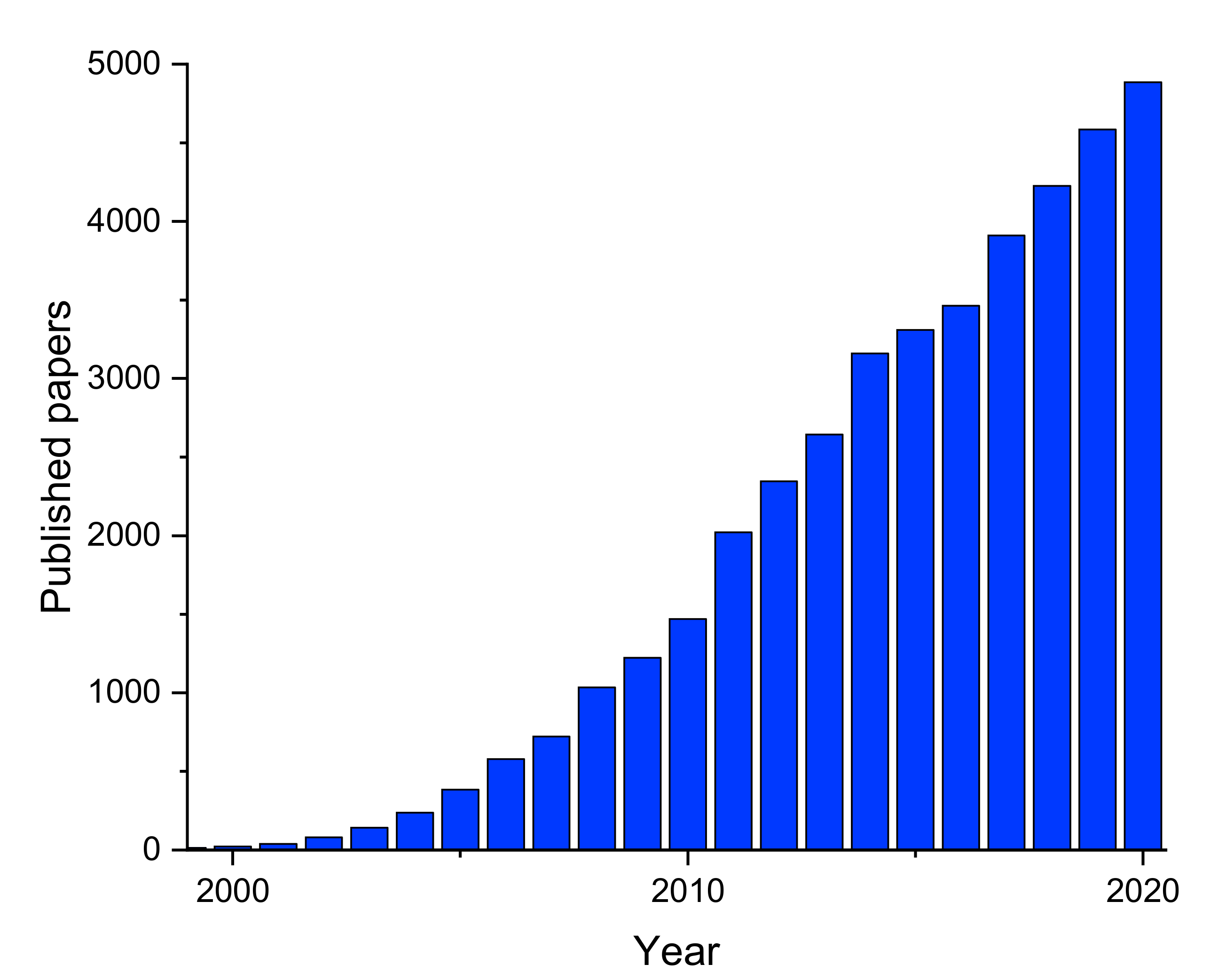
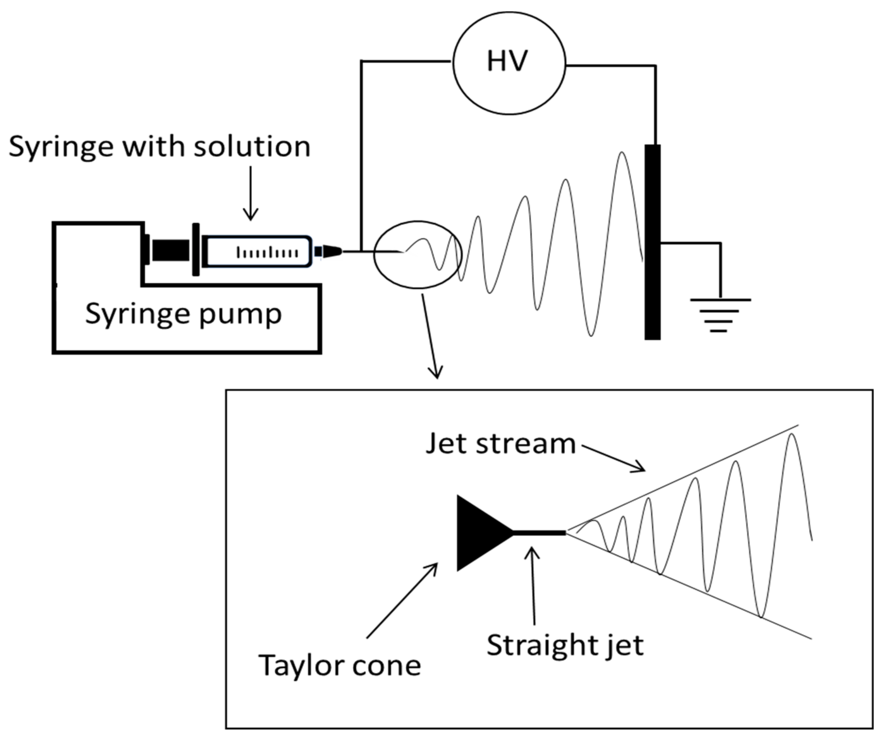
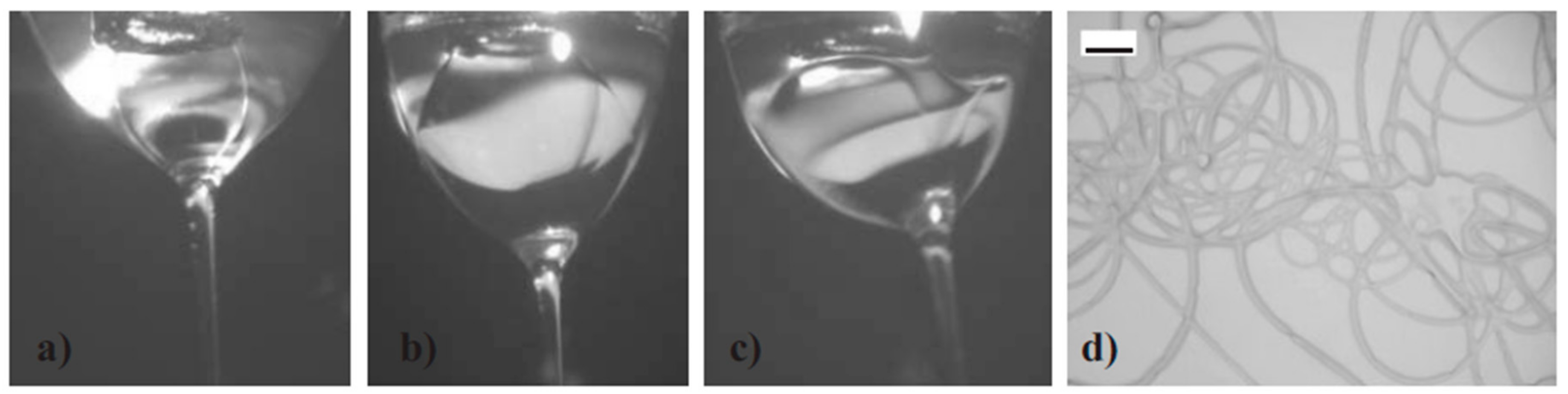
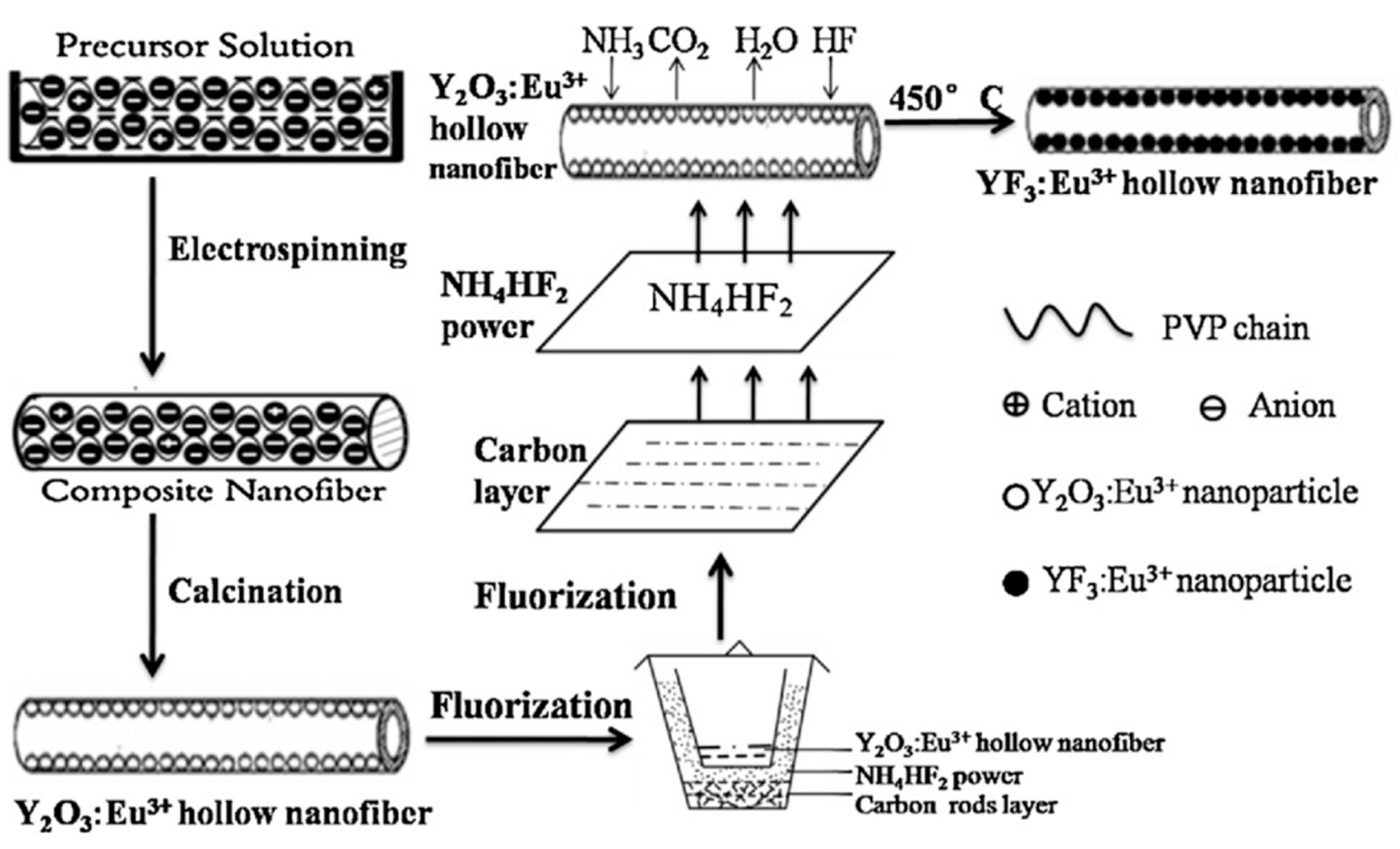
Table 1.
Oxides grown with the electrospinning technique: physical and optical properties.
| Crystal | Active Ion | Diameter (nm) | lp (nm) | lem (nm) | Ref. |
|---|---|---|---|---|---|
| Ba5Si8O21 | Eu2+, Nd3+ | 2000 | 341 | 365–650 | [31] |
| CaAl12O19 | Mn4+ | 500 | 325, 390, 457 | 600–700 | [32] |
| Ca2MgSi2O7 | Eu2+, Dy3+ | 2500 | 378 | 430–650 | [33] |
| CaMoO4 | Eu3+ | 80–150 | 280 | 591, 615 | [30] |
| CaMoO4 | Tb3+ | 80–150 | 283 | 543 | [30] |
| CaMoO4 | Dy3+ | 80–150 | 285 | 478, 487, 576 | [30] |
| CaSi2O2N2 | Eu3+ | 200–300 | - | 500-600 | [34] |
| Ca (Sr)Al2Si2O8 | Eu3+ | 500 | 263, 393 | 580, 529, 614, 654 | [35] |
| Ca (Sr)Al2Si2O8 | Eu2+ | 500 | 330 | 428 | [35] |
| Ca (Sr)Al2Si2O8 | Eu2+, Dy3+ | 500 | 330 | 428 | [35] |
| CaTiO3 | Pr3+ | 500 | 330 | 615 | [36] |
| CaAl2Si2O8 | Eu2+, Dy3+ | 200–800 | 350 | 428 | [36] |
| Ca4Y6(SiO4)6O | Eu3+ | 120–260 | 277 | 540,580, 588, 616, 655, 705 | [37] |
| Ca4Y6(SiO4)6O | Tb3+ | 120–260 | 235 | 418, 440, 488, 545, 585, 624 | [37] |
| Ca2RE8(SiO4)6O2 (RE = Y, Gd) | Pb2+, Dy3+ | 140–190 | 254 | 347, 482, 574 | [38] |
| CaWO4 | Tb3+ | 50–150 | 249 | 382, 415, 436, 466, 545, 585, 619 | [39] |
| CeO2 | Ce3+ | 300 | - | - | [40] |
| CuAlO2 | Eu3+ | - | 365, 465 | 587, 610, 654, 690 | [41] |
| EuOF | Eu3+ | 800 | 290 | 579, 591, 609, 654, 706 | [42] |
| Ga2O3 | Eu3+ | 180–300 | 325 | 598, 620, 665, 704 | [1] |
| Ga2O3 | Tb3+ | 100–300 | 325 | 491, 550, 591, 625 | [43] |
| Gd2O3 | Tb3+ | 80 | 274 | 493, 545, 595, 619 | [44] |
| Gd2O3 | Eu3+ | 60–150 | 254 | 587, 615, 629 | [45] |
| GeO2 | Er3+ | 388 ± 186 | 488 | 1540 | [46] |
| GdVO4 | Eu3+ | 100–160 | 276 | 620 | [47] |
| GdVO4 | Dy3+ | 100–160 | 276 | 484, 574 | [47] |
| GdVO4 | Sm3+ | 100–160 | 276 | 567, 604, 649 | [47] |
| HoOF | Ho3+ | 750 | 290 | 416, 488, 528, 555; 652, 660 | [42] |
| LaBO3 | Eu3+ | 100 | 254 | 550–700 | [48] |
| LaBO3 | Tb3+ | 100 | 254 | 485, 543, 582, 622, | [48] |
| LaOBr | Tb3+ | 90 ± 15 | 253 | 418, 438, 486, 543 | [49] |
| LaOBr | Er3+ | 3060 ± 420 | 980 | 522, 541, 667,1500 (@ex.532) | [50] |
| LaOCl | Eu3+ | 100–200 | 295 | 531, 554, 577, 594, 615, 648, 698 | [51] |
| LaOCl | Sm3+ | 100–200 | - | - | [51] |
| LaOCl | Tb3+ | 100–200 | 234 | 382, 415, 438, 486, 543, 584, 621 | [51] |
| LaOCl | Tb3+, Eu3+ | 100–200 | 488 | 543, 615 | [51] |
| LaOCl | Tm3+, Eu3+ | 100–200 | 488 | 382, 415, 438, 486, 543, 584, 621 | [51] |
| LaPO4 | Ce3+ | 75–150 | 278 | 318, 336, | [52] |
| LaPO4 | Tb3+ | 75–150 | 216 | 489, 543, 585, 620 | [52] |
| LaPO4 | Ce3+, Tb3+ | 75–150 | 278 | 487, 543, 583, 619 | [52] |
| La2W2O9 | Eu3+ | 184 ± 19 | 288 | 533, 570-700 | [53] |
| Lu2O3 | Eu3+ | 90–180 | 237 | 612 | [54] |
| Lu2O2S | Eu3+ | 252 | 345 | 610 | [55] |
| SnO2 | Er3+ | ~590 | 488 | 1540 | [56] |
| SrAl2O4 | Eu2+, Dy3+ | 180–200 | 346–375 | 509 broadband | [57] |
| SrAl2O4 | Eu2+ | 600 | 348 | 515 | [36] |
| SrAl2O4 | Eu2+, Dy3+ | 600 | 348 | 515 | [36] |
| Sr2MgSi2O7 | Eu2+, Dy3+ | 1500 | 360 | 410–590 | [58] |
| SrRe0.6Fe11.4O19 | Ce3+ | 200–300 | - | - | [59] |
| Tb2(WO4)3 | Tb3+ | 80–150 | 280 | 488, 543, 585, 619 | [60] |
| Tb2(WO4)3 | Tb3+, Eu3+ | 80–150 | 280 | 488, 543, 592, 652, 702 | [60] |
| TiO2 | Eu3+ | 80–100 | 395 | 580, 595, 615 | [61] |
| TiO2 | Eu3+ | 60–70 | CL | 580, 595, 615, 652, 700 | [62] |
| TiO2 | Er3+ | 60–80 | CL | 567, 528, 669 | [62] |
| TiO2 | Sm3+ | 1000 | 330 | 580, 610, 660 | [63] |
| TiO2 | Ce3+ | 700 | - | - | [64] |
| TiO2 | Nd3+ | 340 | - | - | [64] |
| TiO2 | Er3+ | 160 | - | - | [65] |
| TiO2 | Er3+ | 75 | 325 | 528, 567, 669, 815 | [66] |
| TiO2 | Eu3+ | 150 | UV | ~650-750 | [67] |
| TiO2 | Er3+ | 150 | UV | ~700 | [67] |
| TiO2 | Ce3+ | 150 | UV | ~700 | [67] |
| TiO2 | Pr3+ | 150 | UV | ~400–420 | [67] |
| TiO2 | Eu3+ | 20–100 | 325 | 600, 621, 667, 695 | [68] |
| TiO2/SiO2 | Er3+ | - | - | - | [69] |
| Ce2O3/TiO2 | Ce3+ | 300 | - | - | [70] |
| YAG | Yb3+, Er3+ | 1800 ± 370 | 980 | 522, 554, 648 | [71] |
| YAG | Eu3+ | 3250 | 235 | 592, 597, 611, 632 | [72] |
| YAG | Tb3+ | 166 ± 20 | 274 | 486, 544, 587, 623 | [73] |
| YAG | Ce3+, Tb3+ | 4090 ± 410 | 273 | 490, 544, 584 | [74] |
| YAG | Dy3+ | 3850 ± 900 | 352 | 452, 484, 583 | [75] |
| YAG | Er3+ | 590 ± 190 | 381 | 510-580, 630-690 | [17] |
| YAG | Eu3+ | 400-500 | 238 | 592, 612, 650, 708 | [76] |
| YAG | Ce3+ | 300 | 470 | 530 | [77] |
| YAG | Ce3+ | 200–250 | 450 | 500–600 | [78] |
| YAG-Al2O3 | Eu3+ | 300 | 395 | 570–720 | [79] |
| YBO3 | Eu3+ | 40 | 245 | 591, 609, 624 | [80] |
| Y2O3 | Eu3+ | 300 | 260 | 578, 592, 612, 652, 688 | [81] |
| Y2O3 | Eu3+ | 184 ± 26 | 260 | 581, 588, 594, 612, 632 | [82] |
| Y2O3 | Tb3+ | 35–260 | 304 | ~500 | [83] |
| Y2O3 | Sm3+ | 35–260 | - | - | [83] |
| Y2O3 | Dy3+ | 35–260 | 458 | ~600 | [83] |
| Y2O3 | Eu3+ | 200–400 | 241 | 609 | [84] |
| Y2O2S | Eu3 | 137 ± 18 | 260 | 515, 540, 557, 584, 588, 596, 618, 628 | [82] |
| Y2SiO5 | Ce3+ | 70–140 | 367 | 437 | [85] |
| Y2SiO5 | Tb3+ | 70–140 | 248 | 489, 542, 585, 625 | [85] |
| Y2SiO5 | Ce3+, Tb3+ | 70–140 | 367 | 437, 489, 542, 585, 625 | [85] |
| YVO4 | Eu3+ | 30–50 | 280 | ~600 | [86] |
| YVO4 | Eu3+ | 30 | 280 | ~600 | [87] |
| PEO/YVO4 | Eu3+ | 300 | 290 | 593, 615, 650, 698 | [88] |
| Y (V, P) O4 | Eu3+ | 50–100 | 290 | 538, 587, 618, 698 | [89] |
| Y (V, P) O4 | Sm3+ | 50–100 | 280 | 567, 602, 649 | [89] |
| Y (V, P) O4 | Dy3+ | 50–100 | 280 | 483, 573 | [89] |
| ZnAl2O4 | Ni2+ | 120 | 576 | 1000–1400 | [90] |
| ZnAl2O4 | Cr3+ | 140–230 | 400 | 689 | [91] |
| ZnAl2O4 | Eu3+ | 140–230 | 278 | 570–720 | [91] |
| ZnAl2O4 | Tb3+ | 140–230 | 227 | 380, 415, 438, 490, 545, 587 | [91] |
| ZnAl2O4 | Nd3+ | ~200 | 808 | 905, 1064, 1330 | [92] |
| ZnGa2O4 | Mn2+ | 96 | 246 | 505 | [93] |
| ZnO | Ce3+ | 350 | 325, 350, 365 | 400–600 | [21] |
| ZnO | Er3+ | 600 | - | - | [94] |
| ZnO | Sm3+ | 600 | - | - | [94] |
| ZnS | Cu2+ | 300 | 315 | 450–600 | [95] |
| ZrO2 | Tb3+ | 250 | 325 | 488, 543, 584, 620 | [96] |
Table 2.
Fluorides grown with the electrospinning technique: physical and optical properties.
| Crystal | Dopant/s | Diameter (nm) | lp(nm) | lem(nm) | Ref |
|---|---|---|---|---|---|
| BaY2F8 | Er3+ | 160 ± 16 | 980 | 523, 540, 652 | [97] |
| BaYF5 | Er3+ | 110 ± 11 | 980 | 522, 540, 651 | [16] |
| Ba4Y3F17 | Er3+ | 84 ± 5 | 980 | 523, 541, 652 | [98] |
| NaY/GdF4 | Yb3+, Er3+ | 75–200 | 980 | 510–570, 630–700 | [12] |
| NaGdF4 | Eu3+ | 231 ± 4 | 274 | 417, 430, 446, 465, 489, 511, 536, 556, 584, 592, 616 | [13] |
| NaGdF4 | Dy3+, Eu3+ | 246 ± 52 | 274 | 478, 570, 592, 616 | [99] |
| NaGdF4 | Yb3+, Er3+ | - | 274 | 521, 542, 652 | [100] |
| NaGdF4 | Eu3+ | 200 | 273 | 525-650 | [101] |
| NaYF4 | Yb3+, Er3+ | About 200 | 980 | 562, 655, 663, 673 | [102] |
| NaYF4 | Yb3+, Er3+ | About 300 | 980 | 510–575, 660–675 | [103] |
| NaYF4 | Yb3+, Er3+ | 300–750 | 980 | 522, 542, 655 | [104] |
| NaYF4 | Yb3+, Er3+ | 316 ± 66 | 980 | 523, 539, 656 | [105] |
| NaYF4 | Yb3+, Er3+, Tm3+ | 300–800 | 980 | 476, 451, 550, 649, 660-740 | [106] |
| NaYF4 | Yb3+, Er3+ | 400 | 980 | 375, 405, 538,520, 655 | [107] |
| NaYF4 | Tb3+, Ce3+ | 400 | 254 | 280-420, 375, 414, 438, 465, 490, 544, 586, 622 | [108] |
| NaYF4 | Yb3+, Er3+ | 260 | 980 | 479, 487, 542, 789 | [109] |
| La2Ti2O7 | Tm3+, Yb3+ | 500–1000 | 977 | 550, 650 | [110] |
| YF3 | Yb3+, Tm3+ | 200–300 | 980 | 291, 346, 362, 453, 477, 642, 802 | [111] |
| YF3 | Tb3+ | 148 ± 23 | 367 | 490, 543, 588, 620 | [22] |
| YF3 | Eu3+ | 211 ± 29 | 394 | 587, 593, 615, 620 | [112] |
| YF3 | Eu3+ | 197 ± 34 | 394 | 555, 587, 593, 615, 620, 651, 692 | [29] |
| Y2Ti2O7 | Ho3+, Yb3 | 300–400 | 977 | 550, 650 | [113] |
| GdF3 | Eu3+ | 86.5 ± 0.5 | 274 | 418, 430, 445, 464, 489, 510, 538, 555, 587, 594, 615 | [19] |
| BaFCl | Eu2+ | 193 ± 1 | 275 | 387 | [114] |
Publisher’s Note: MDPI stays neutral with regard to jurisdictional claims in published maps and institutional affiliations. |
© 2021 by the author. Licensee MDPI, Basel, Switzerland. This article is an open access article distributed under the terms and conditions of the Creative Commons Attribution (CC BY) license (https://creativecommons.org/licenses/by/4.0/).
Share and Cite
MDPI and ACS Style
Toncelli, A. RE-Based Inorganic-Crystal Nanofibers Produced by Electrospinning for Photonic Applications. Materials 2021, 14, 2679. https://doi.org/10.3390/ma14102679
AMA Style
Toncelli A. RE-Based Inorganic-Crystal Nanofibers Produced by Electrospinning for Photonic Applications. Materials. 2021; 14(10):2679. https://doi.org/10.3390/ma14102679
Chicago/Turabian StyleToncelli, Alessandra. 2021. "RE-Based Inorganic-Crystal Nanofibers Produced by Electrospinning for Photonic Applications" Materials 14, no. 10: 2679. https://doi.org/10.3390/ma14102679
Note that from the first issue of 2016, this journal uses article numbers instead of page numbers. See further details here.