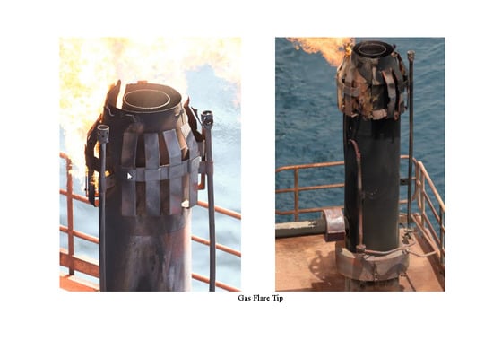
Failure Analysis of a Flare Tip Used in Offshore Production Platform in Qatar


Abstract
:
1. Introduction
2. Experimental Investigation Program
3. Results and Discussion
3.1. Chemical Analysis and Microstructural Characterization
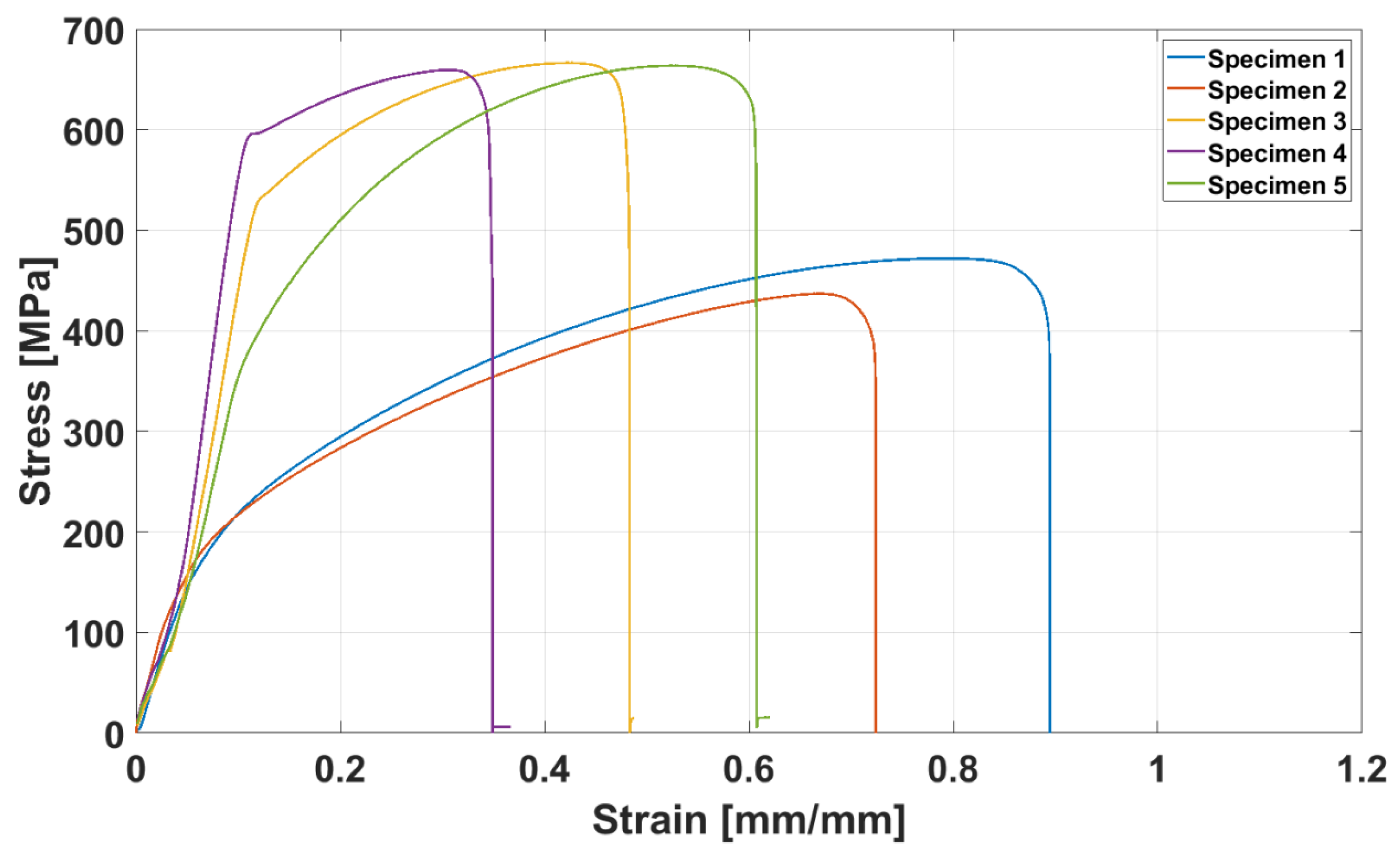
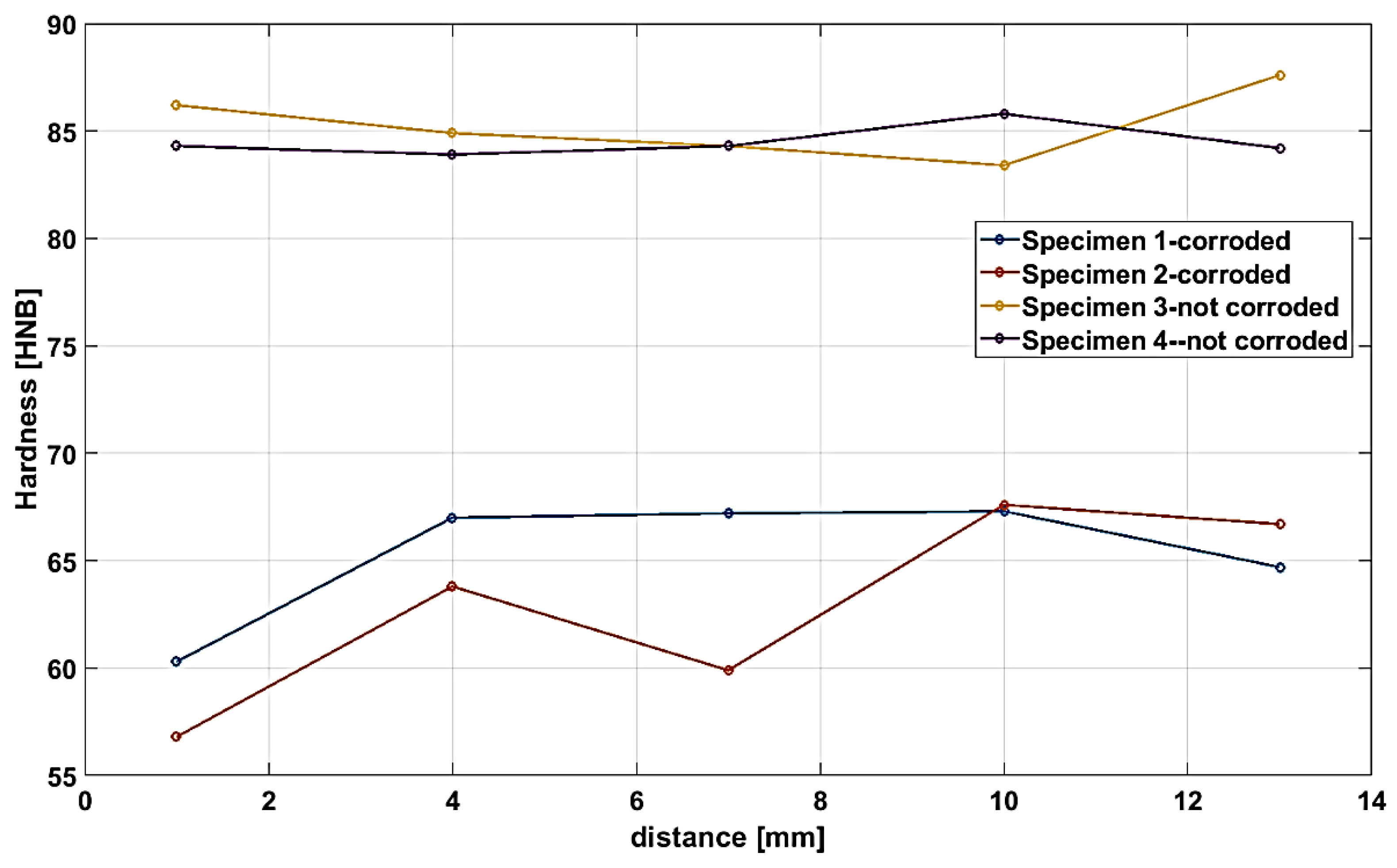
3.2. Mechanical Properties
3.3. The Root Cause of Failure
4. Conclusion
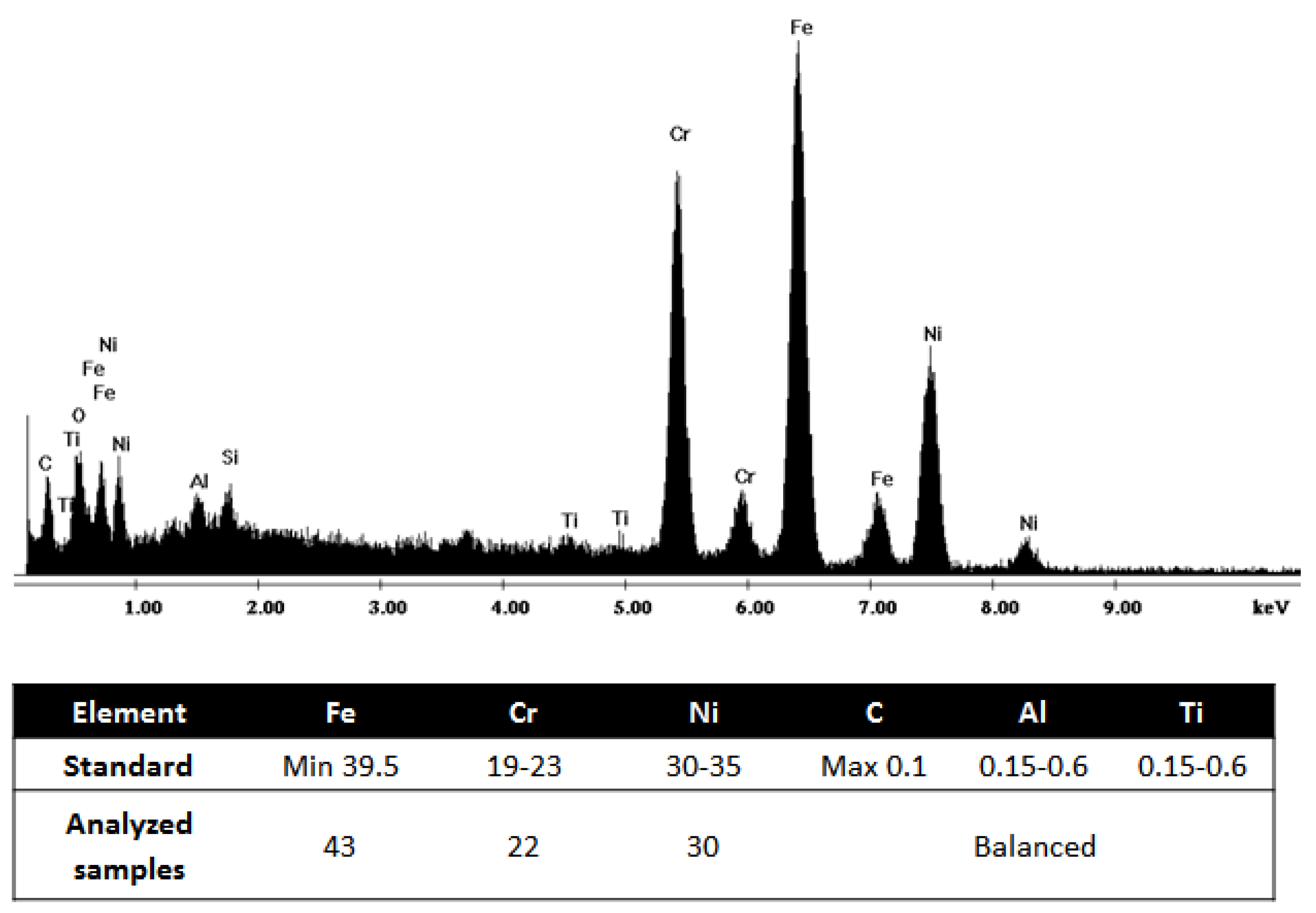
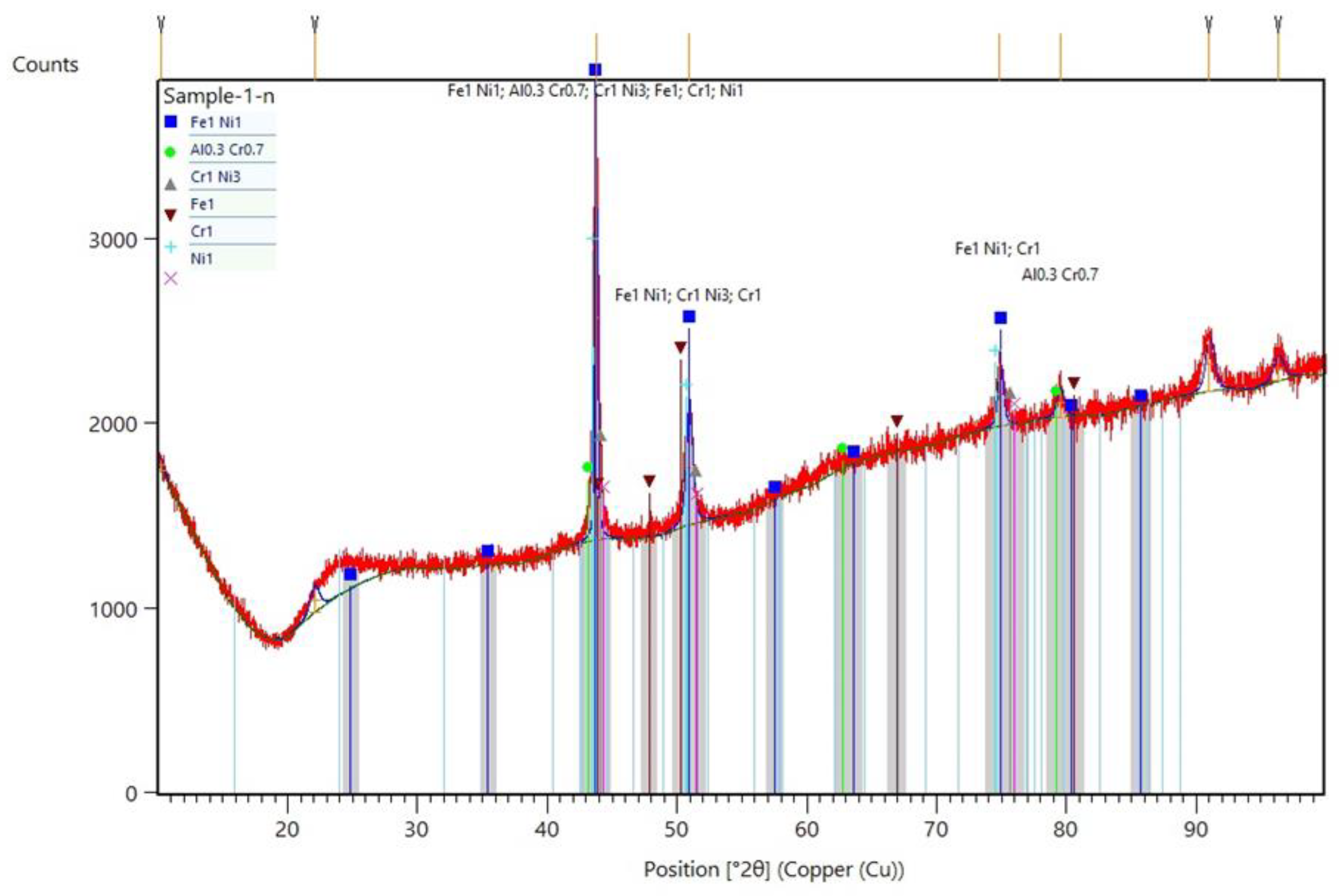
- The microstructure illustrated that flare material contained Fe, Cr and Ni, as well as the presence of the small amount of other alloying elements such as Al, Ti and C, which were in accordance with the reference material.
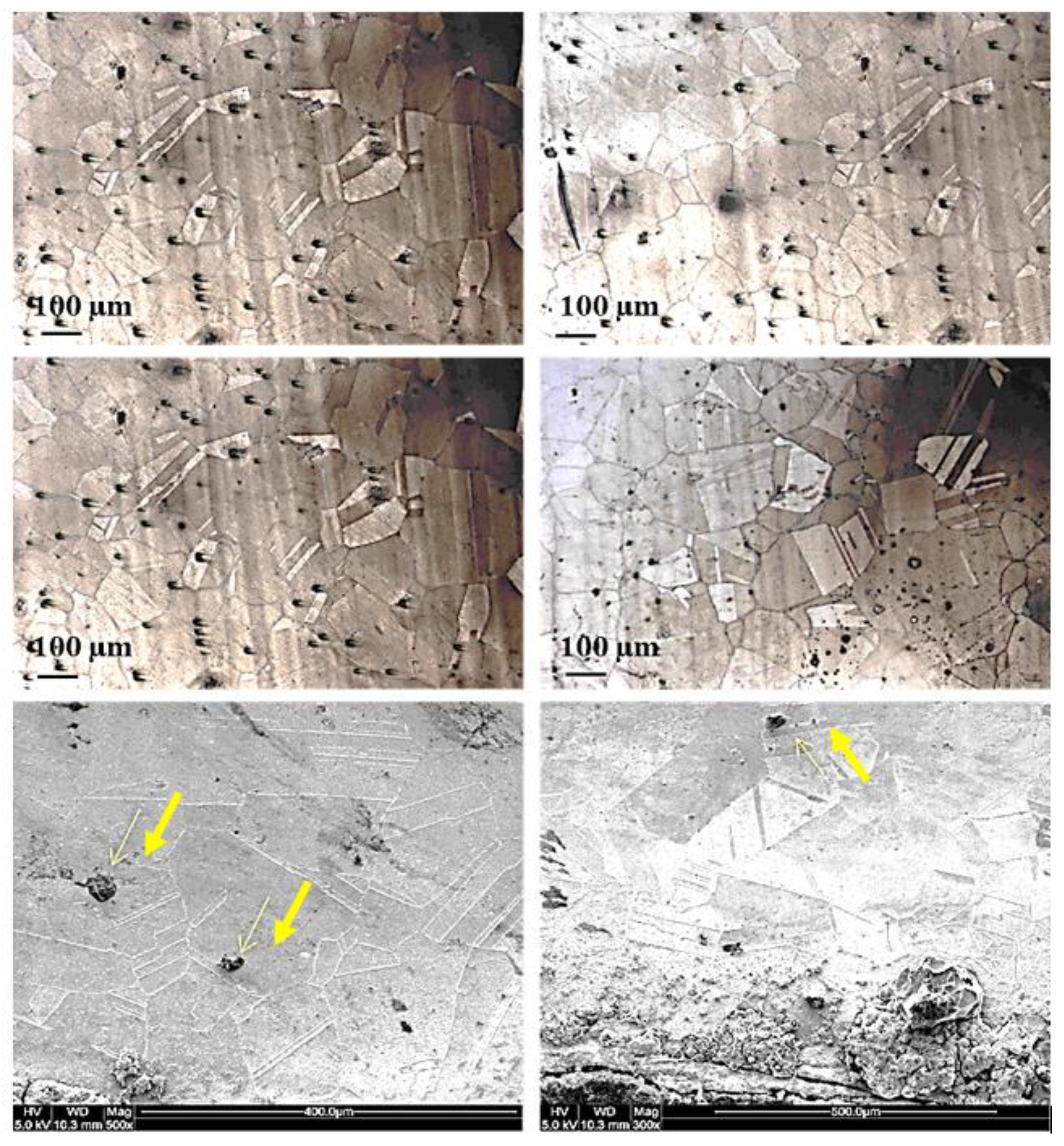
- The average grain size of 100 µm was obtained for the analyzed material, which was also in agreement with the reference materials.
- Presences of the twining system, as well as the formation of tiny precipitates such as TiC along the examined surfaces, were also noticed from the microstructural characterization.
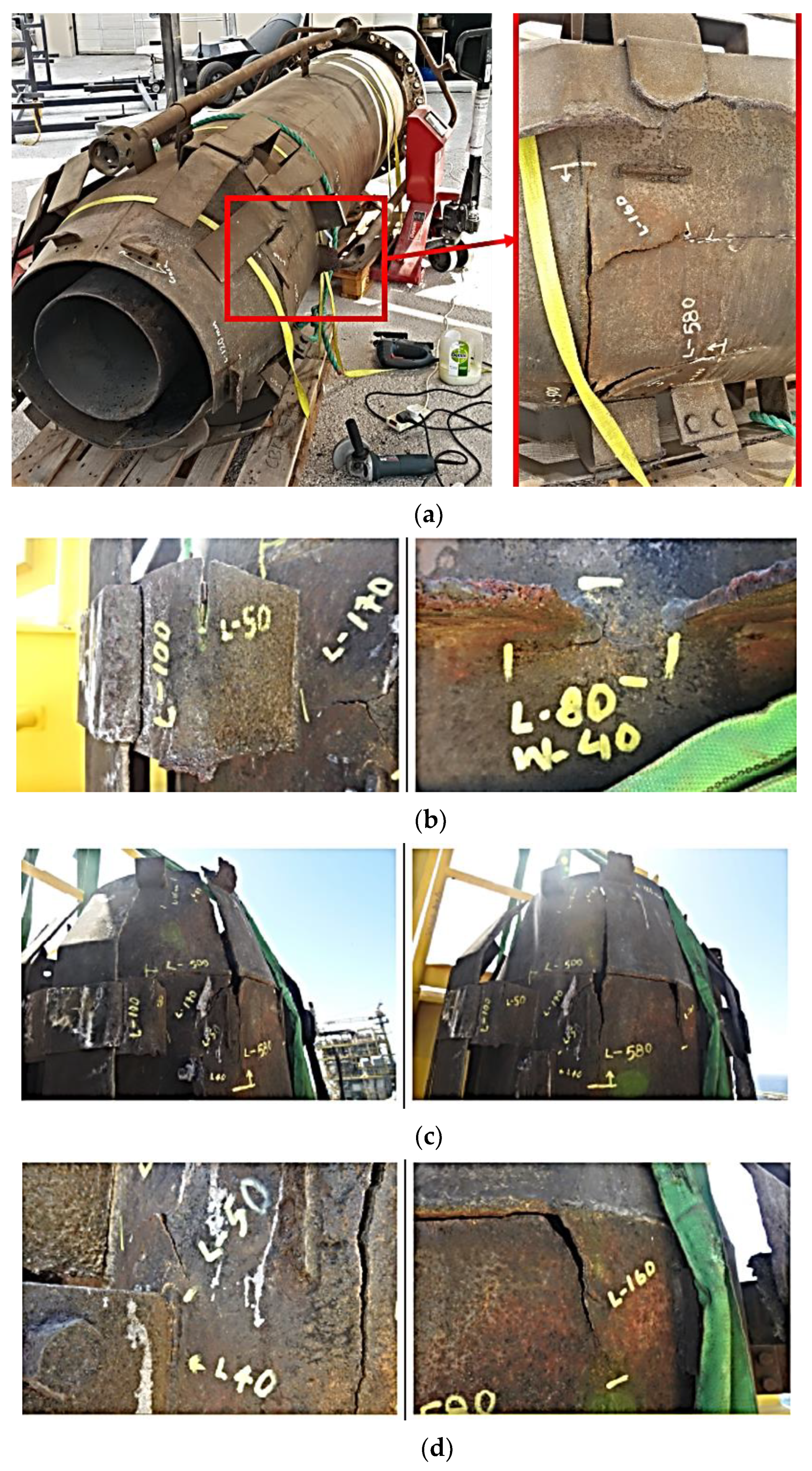
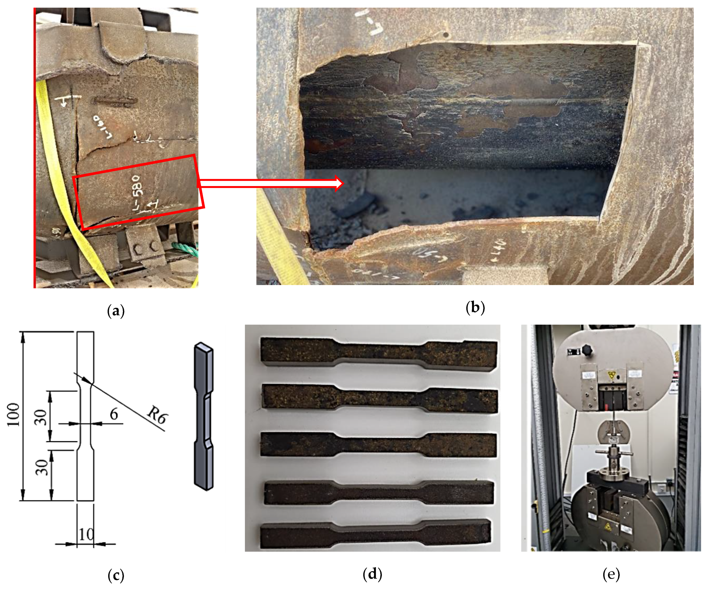
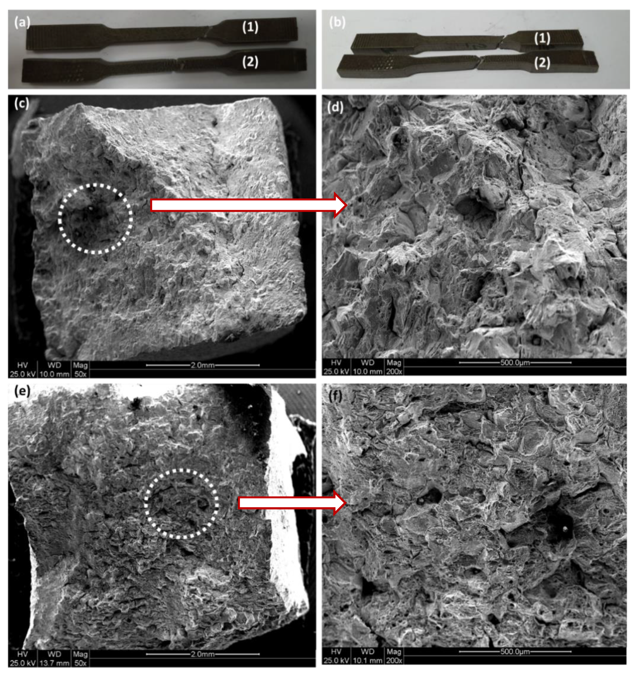
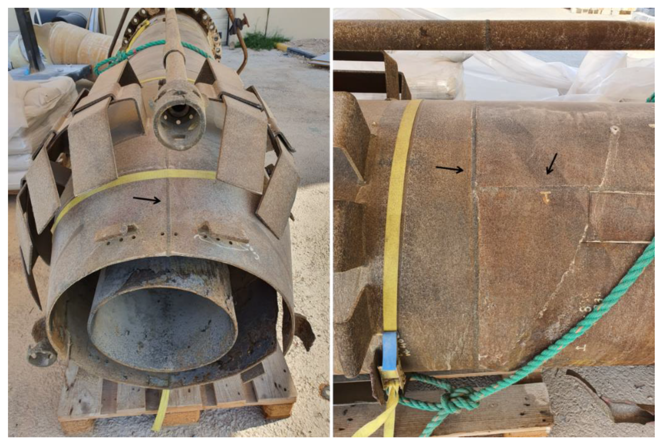
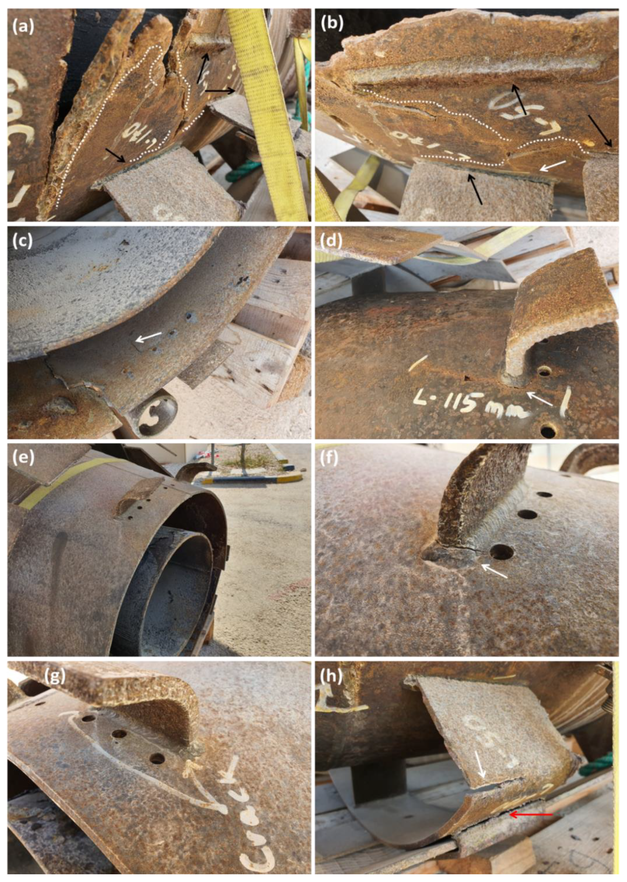
- Careful examination of the failed parts indicated that failure mostly took place in the vicinity of the welds, in particular near the joints.
- Improper joint designs, as well as designing a high number of joints in tiny areas, worsened the harmful effect of HAZ, resulting in crack nucleation in the HAZ regions.
5. Recommendations
- The configuration of the joints should be optimized in a way to reduce the harmful effect of HAZ.
- In addition, the number of joints should also be reduced due to the fact that they connect to the flare boy using a joint.
- Moreover, the blind designs for the joints used for pockets should be improved, i.e., at least a two-sides joint should be performed. Herein, finite element analysis will be very useful to avoid the inappropriate design of the joints.
Author Contributions
Funding
Acknowledgments
Conflicts of Interest
References
- Nafari, M.; Golezani, A.S. Heat affected zone creep characterization of INCOLOY 800H by means of small punch test. Eng. Fail. Anal. 2018, 94, 407–411. [Google Scholar] [CrossRef]
- Sayiram, G.; Arivazhagan, N. Microstructural characterization of dissimilar welds between Incoloy 800H and 321 Austenitic Stainless Steel. Mater. Charact. 2015, 102, 180–188. [Google Scholar] [CrossRef]
- Akhiani, H.; Nezakat, M.; Sanayei, M.; Szpunar, J. The effect of thermo-mechanical processing on grain boundary character distribution in Incoloy 800H/HT. Mater. Sci. Eng. A 2015, 626, 51–60. [Google Scholar] [CrossRef]
- Zaragoza-Granados, J.; Gallardo-Hernández, E.A.; Vite-Torres, M.; la Rosa, C.S. Erosion behavior of AISI 310 stainless steel at 450 °C under turbulent swirling impinging jets. Wear 2019, 426–427, 637–642. [Google Scholar] [CrossRef]
- Naffakh, H.; Shamanian, M.; Ashrafizadeh, F. Dissimilar welding of AISI 310 austenitic stainless steel to nickel-based alloy Inconel 657. J. Mater. Process. Technol. 2009, 209, 3628–3639. [Google Scholar] [CrossRef]
- Shah Hosseini, H.; Shamanian, M.; Kermanpur, A. Characterization of microstructures and mechanical properties of Inconel 617/310 stainless steel dissimilar welds. Mater. Charact. 2011, 62, 425–431. [Google Scholar] [CrossRef]
- Davoudi, M.; Rahimpour, M.R.; Jokar, S.; Nikbakht, F.; Abbasfard, H. The major sources of gas flaring and air contamination in the natural gas processing plants: A case study. J. Nat. Gas Sci. Eng. 2013, 13, 7–19. [Google Scholar] [CrossRef]
- Mahdi, E.; Nasser, K.; Gharbia, M. Optimization of Flare Header Platform Design in a Liquefied Natural Gas Plant. Proc. Annu. Gas Process. Symp. 2010, 359–367. [Google Scholar] [CrossRef]
- Kazi, M.-K.; Eljack, F.T.; Al-Sobhi, S.A.; Kazantzis, N.; Kazantzi, V. Application of i-SDT for safer flare management operation. Process. Saf. Environ. Prot. 2019, 132, 249–264. [Google Scholar] [CrossRef]
- Kazi, M.-K.; Eljack, F.; Al-Sobhi, S.A.; Kazantzis, N.; Kazantzi, V. Process Dynamic Analysis and Control Strategy for COGEN option Used for Flare Utilization. Softw. Archit. Tools Comput. Aided Process Eng. 2019, 46, 1255–1260. [Google Scholar]
- Xu, Y.; Dinh, H.; Xu, Q.; Eljack, F.T.; El-Halwagi, M.M. Flare minimization for an olefin plant shutdown via plant-wide dynamic simulation. J. Clean. Prod. 2020, 254, 120129. [Google Scholar] [CrossRef]
- Strosher, M.T. Characterization of emissions from diffusion flare systems. J. Air Waste Manag. Assoc. 2000, 50, 1723–1733. [Google Scholar] [CrossRef] [PubMed]
- Jo, Y.-P.; Cho, Y.; Hwang, S. Dynamic analysis and optimization of flare network system for topside process of offshore plant. Process. Saf. Environ. Prot. 2020, 134, 260–269. [Google Scholar] [CrossRef]
- Kraus, C.; Falk, T.; Mauermann, R.; Drossel, W.G. Development of a New Self-flaring Rivet Geometry Using Finite Element Method and Design of Experiments. Procedia Manuf. 2020, 47, 383–388. [Google Scholar] [CrossRef]
- Capar, I.D.; Ertas, H.; Arslan, H. Comparison of Cyclic Fatigue Resistance of Nickel-Titanium Coronal Flaring Instruments. J. Endod. 2014, 40, 1182–1185. [Google Scholar] [CrossRef] [PubMed]
- Fischer, F.; Rammerstorfer, F.; Daxner, T. Flaring—An analytical approach. Int. J. Mech. Sci. 2006, 48, 1246–1255. [Google Scholar] [CrossRef]
- Zahrani, E.M.; Saatchi, A.; Alfantazi, A. Pitting of 316L stainless steel in flare piping of a petrochemical plant. Eng. Fail. Anal. 2010, 17, 810–817. [Google Scholar] [CrossRef]
- Becker, W.T.; Shipley, R.J. Failure Analysis and Prevention; ASM International: Cleveland, OH, USA, 2002. [Google Scholar] [CrossRef] [Green Version]
- Vicente, C.M.; Sardinha, M.; Reis, L. Failure analysis of a coupled shaft from a shredder. Eng. Fail. Anal. 2019, 103, 384–391. [Google Scholar] [CrossRef]
- Mahdi, E.; Rauf, A.; Ghani, S.; El-Noamany, A.; Pakari, A. Erosion-Corrosion Behavior and Failure Analysis of Offshore Steel Tubular Joint. Int. J. Electrochem. Sci. 2013, 8, 7187–7210. [Google Scholar]
- American Petroleum Institute. API STD 537 Flare Details for General Refinery and Petrochemical Service, 1st ed.; American Petroleum Institute: Washington, DC, USA, 2003. [Google Scholar]
- Emam, E.A. GAS flaring in the industry: An overview. Pet. Coal 2015, 57, 532–555. [Google Scholar]
- Yousefi, M.; Farghadin, M.H.; Farzadi, A. Investigate the causes of cracks in welded 310 stainless steel used in the Flare tip. Eng. Fail. Anal. 2015, 53, 138–147. [Google Scholar] [CrossRef]
- Soltani, A.; Farzanfar, K.; Zarei, R. Failure analysis of corroded and cracked flare tip of material SS310 in phase 12 gas refinery of South Pars Gas Complex. Eur. Corros. Congr. 2016, 2016, 3079–3089. [Google Scholar]
- Taie, I.; Al-Shahrani, A.; Qari, N.; Fihri, A.; Al-Obaid, W.; Alabedi, G. High temperature corrosion resistant coatings for gas flare systems. Ceram. Int. 2018, 44, 5124–5130. [Google Scholar] [CrossRef]
- Elshawesh, F.; Elhoud, A.; Zeglam, W.; Abusowa, K.; Mesalem, A. Corrosion Fatigue of Incoloy 825 Flare Gas Line Bellows of Expansion Joints. J. Fail. Anal. Prev. 2014, 15, 7–14. [Google Scholar] [CrossRef]
- ASTM International. E8/E8M—16a Standard Test Methods for Tension Testing of Metallic Materials; ASTM: West Conshohocken, PA, USA, 2016. [Google Scholar]
- ASTM International. ASTM E 3—01 Standard Guide for Preparation of Metallographic Specimens; ASTM: West Conshohocken, PA, USA, 2001. [Google Scholar]
- Mishra, D.; Dakkili, M. Gas tungsten and shielded metal arc welding of stainless steel 310 and 304 grades over single and double ‘V’ butt joints. Mater. Today Proc. 2020, 27, 772–776. [Google Scholar] [CrossRef]
- Mukhopadhyay, G. Construction failures due to improper materials, manufacturing, and design. In Handbook of Materials Failure Analysis, With Case Studies from the Construction Industries; Makhlouf, A.S.H., Aliofkhazraei, M., Eds.; Butterworth-Heinemann Ltd.: Oxford, UK, 2018; Chapter 4; pp. 59–81. [Google Scholar]


| Row | Name | Material |
|---|---|---|
| 1 | Body Upper | Alloy 800H |
| 2 | Body lower | 316 L SS |
| 3 | HP outlet nozzle | Alloy 800H |
| 4 | LP outlet duct | Alloy 800 H |
| 5 | Pilot | 316 L SS |
| 6 | Pilot nozzle | Alloy 550 |
| 7 | Pilot gas manifold | 316 SS |
| 8 | Wind deflector | Alloy 800H |
© 2020 by the authors. Licensee MDPI, Basel, Switzerland. This article is an open access article distributed under the terms and conditions of the Creative Commons Attribution (CC BY) license (http://creativecommons.org/licenses/by/4.0/).
Share and Cite
Mahdi, E.; Esmaeili, A. Failure Analysis of a Flare Tip Used in Offshore Production Platform in Qatar. Materials 2020, 13, 3426. https://doi.org/10.3390/ma13153426
Mahdi E, Esmaeili A. Failure Analysis of a Flare Tip Used in Offshore Production Platform in Qatar. Materials. 2020; 13(15):3426. https://doi.org/10.3390/ma13153426
Chicago/Turabian StyleMahdi, Elsadig, and Ali Esmaeili. 2020. "Failure Analysis of a Flare Tip Used in Offshore Production Platform in Qatar" Materials 13, no. 15: 3426. https://doi.org/10.3390/ma13153426